402 handling and processing of radioactive waste from ... · handling and processing of radioactive...
TRANSCRIPT

Handling and Processingof Radioactive Waste from
Nuclear Applications
INTERNATIONAL ATOMIC ENERGY AGENCY, VIENNA, 2001
TTEECCHHNNIICCAALL RREEPPOORRTTSS SSEERRIIEESS NNoo..
Slurrywaste
Dewateringtank
orliquidwaste
Mixing tank
Cementsilo
Additives
Feeder
Mixing pump
Cemented wasteto storage
402

HANDLING AND PROCESSINGOF RADIOACTIVE WASTE FROM
NUCLEAR APPLICATIONS

The Agency’s Statute was approved on 23 October 1956 by the Conference on the Statute of theIAEA held at United Nations Headquarters, New York; it entered into force on 29 July 1957. TheHeadquarters of the Agency are situated in Vienna. Its principal objective is “to accelerate and enlarge thecontribution of atomic energy to peace, health and prosperity throughout the world’’.
© IAEA, 2001
Permission to reproduce or translate the information contained in this publication may beobtained by writing to the International Atomic Energy Agency, Wagramer Strasse 5, P.O. Box 100,A-1400 Vienna, Austria.
Printed by the IAEA in AustriaOctober 2001
STI/DOC/010/402
The following States are Members of the International Atomic Energy Agency:
AFGHANISTANALBANIAALGERIAANGOLAARGENTINAARMENIAAUSTRALIAAUSTRIAAZERBAIJAN, REPUBLIC OFBANGLADESHBELARUSBELGIUMBENINBOLIVIABOSNIA AND HERZEGOVINABRAZILBULGARIABURKINA FASOCAMBODIACAMEROONCANADACENTRAL AFRICAN
REPUBLICCHILECHINACOLOMBIACOSTA RICACOTE D’IVOIRECROATIACUBACYPRUSCZECH REPUBLICDEMOCRATIC REPUBLIC
OF THE CONGODENMARKDOMINICAN REPUBLICECUADOREGYPTEL SALVADORESTONIAETHIOPIAFINLANDFRANCEGABONGEORGIAGERMANY
GHANAGREECEGUATEMALAHAITIHOLY SEEHUNGARYICELANDINDIAINDONESIAIRAN, ISLAMIC REPUBLIC OF IRAQIRELANDISRAELITALYJAMAICAJAPANJORDANKAZAKHSTANKENYAKOREA, REPUBLIC OFKUWAITLATVIALEBANONLIBERIALIBYAN ARAB JAMAHIRIYALIECHTENSTEINLITHUANIALUXEMBOURGMADAGASCARMALAYSIAMALIMALTAMARSHALL ISLANDSMAURITIUSMEXICOMONACOMONGOLIAMOROCCOMYANMARNAMIBIANETHERLANDSNEW ZEALANDNICARAGUANIGERNIGERIANORWAY
PAKISTANPANAMAPARAGUAYPERUPHILIPPINESPOLANDPORTUGALQATARREPUBLIC OF MOLDOVAROMANIARUSSIAN FEDERATIONSAUDI ARABIASENEGALSIERRA LEONESINGAPORESLOVAKIASLOVENIASOUTH AFRICASPAINSRI LANKASUDANSWEDENSWITZERLANDSYRIAN ARAB REPUBLICTHAILANDTHE FORMER YUGOSLAV
REPUBLIC OF MACEDONIATUNISIATURKEYUGANDAUKRAINEUNITED ARAB EMIRATESUNITED KINGDOM OF
GREAT BRITAIN AND NORTHERN IRELAND
UNITED REPUBLICOF TANZANIA
UNITED STATES OF AMERICAURUGUAYUZBEKISTANVENEZUELAVIET NAMYEMENYUGOSLAVIAZAMBIAZIMBABWE

HANDLING AND PROCESSINGOF RADIOACTIVE WASTE FROM
NUCLEAR APPLICATIONS
TECHNICAL REPORTS SERIES No. 402
INTERNATIONAL ATOMIC ENERGY AGENCYVIENNA, 2001

VIC Library Cataloguing in Publication Data
Handling and processing of radioactive waste from nuclear applications. —Vienna : International Atomic Energy Agency, 2001.
p. ; 24 cm. — (Technical reports series, ISSN 0074–1914 ; no. 402)STI/DOC/010/402ISBN 92–0–100801–5Includes bibliographical references.
1. Radioactive waste disposal. I. International Atomic Energy Agency. II. Series : Technical reports series (International Atomic Energy Agency) ;402.
VICL 01–00260

FOREWORD
A wide variety of technical options is available for processing radioactive wastegenerated in the nuclear power industry and during various nuclear applications. Theselection of an appropriate technology for waste processing depends mainly on thecharacteristics of the waste, the scale of waste production and the requirements for thefinal waste form. Since wastes generated from nuclear applications are very differentin terms of their volumes and characteristics from those generated in the nuclearpower industry, in many cases they require different approaches to the whole systemof treatment, conditioning and storage.
Recognizing the increasing importance of the subject for its Member States, theIAEA has prepared two reports to assist waste managers and waste operators in devel-oping Member States. IAEA-TECDOC-1041, Management of Small Quantities ofRadioactive Waste, was published in 1998 to provide practical guidance and to assistmanagers dealing with small amounts of radioactive waste in developing MemberStates. The document provides information on the different components of the wastemanagement process as a whole and briefly lists the basic technologies used.
This report has been prepared to provide detailed information on the handling,processing and storage techniques most widely used and recommended for wastefrom non-fuel cycle activities mainly in developing Member States. This informationis intended to assist operators of waste processing and storage facilities, with theemphasis on the most simple, affordable and reliable techniques available in non-nuclear power generating countries. The report summarizes the informationpreviously collected and described in a number of technical documents (IAEA TECDOCs) published from 1992 to 1995, which were designed mainly for Member States without nuclear power or fuel cycle activities but that haveradioactive waste generated during the application of nuclear technologies andradioisotopes in industry, medicine, research and education. This report is intended toreview, analyse and summarize this information based on up to date experience andexisting practice.
The initial report was prepared by the Secretariat with the assistance of consul-tants from Austria, Canada, Pakistan, the United Kingdom and the United States ofAmerica. The draft was then revised by a series of consultants meetings based oncomments and additional information collected. The IAEA would like to express itsthanks to all those who took part in the preparation of the report, particularlyP. Colombo (USA) and M. Garamszeghy (Canada) who were involved in the prepa-ration of the final version of this report. The IAEA officer responsible for this reportwas V. Efremenkov from the Waste Technology Section of the Division of NuclearFuel Cycle and Waste Technology.

EDITORIAL NOTE
Although great care has been taken to maintain the accuracy of information containedin this publication, neither the IAEA nor its Member States assume any responsibility forconsequences which may arise from its use.
The mention of names of specific companies or products (whether or not indicated asregistered) does not imply any intention to infringe proprietary rights, nor should it beconstrued as an endorsement or recommendation on the part of the IAEA.

CONTENTS
1. INTRODUCTION . . . . . . . . . . . . . . . . . . . . . . . . . . . . . . . . . . . . . . . . . . 1
1.1. Background . . . . . . . . . . . . . . . . . . . . . . . . . . . . . . . . . . . . . . . . . 11.2. Objective and scope . . . . . . . . . . . . . . . . . . . . . . . . . . . . . . . . . . . 11.3. Structure . . . . . . . . . . . . . . . . . . . . . . . . . . . . . . . . . . . . . . . . . . . 2
2. WASTE ARISINGS . . . . . . . . . . . . . . . . . . . . . . . . . . . . . . . . . . . . . . . . 4
2.1. Sources of waste . . . . . . . . . . . . . . . . . . . . . . . . . . . . . . . . . . . . . 42.1.1. Nuclear research centres . . . . . . . . . . . . . . . . . . . . . . . . . 42.1.2. Hospitals . . . . . . . . . . . . . . . . . . . . . . . . . . . . . . . . . . . . . 52.1.3. Industry . . . . . . . . . . . . . . . . . . . . . . . . . . . . . . . . . . . . . 72.1.4. Universities and research establishments . . . . . . . . . . . . . 102.1.5. Decontamination and decommissioning . . . . . . . . . . . . . 10
2.2. Types and amount of waste arising . . . . . . . . . . . . . . . . . . . . . . . . 102.2.1. Scale of radioactive waste production in Member States . 102.2.2. Aqueous waste generation . . . . . . . . . . . . . . . . . . . . . . . . 132.2.3. Liquid organic waste generation . . . . . . . . . . . . . . . . . . . 15
2.2.3.1. Oils . . . . . . . . . . . . . . . . . . . . . . . . . . . . . . . . . . 152.2.3.2. Scintillation liquids . . . . . . . . . . . . . . . . . . . . . 172.2.3.3. Solvents . . . . . . . . . . . . . . . . . . . . . . . . . . . . . . 18
2.2.4. Solid waste generation . . . . . . . . . . . . . . . . . . . . . . . . . . 182.2.5. Wet solid waste generation . . . . . . . . . . . . . . . . . . . . . . . 19
2.2.5.1. Spent ion exchange resins . . . . . . . . . . . . . . . . . 192.2.5.2. Precipitation sludges . . . . . . . . . . . . . . . . . . . . . 192.2.5.3. Evaporator concentrates . . . . . . . . . . . . . . . . . . 19
2.2.6. Biological waste generation . . . . . . . . . . . . . . . . . . . . . . 202.2.7. Medical waste generation . . . . . . . . . . . . . . . . . . . . . . . . 20
3. WASTE CLASSIFICATION . . . . . . . . . . . . . . . . . . . . . . . . . . . . . . . . . . 21
3.1. General considerations . . . . . . . . . . . . . . . . . . . . . . . . . . . . . . . . . 213.2. Waste classification for handling, treatment and storage . . . . . . . . 213.3. Classification for release from regulatory control . . . . . . . . . . . . . 22
3.3.1. Exemption and clearance concept . . . . . . . . . . . . . . . . . . 223.3.2. Requirements for release to the environment
under authorization . . . . . . . . . . . . . . . . . . . . . . . . . . . . . 233.4. Classification for waste disposal . . . . . . . . . . . . . . . . . . . . . . . . . 24

4. COMPONENTS OF A COMPREHENSIVE WASTE MANAGEMENT SYSTEM . . . . . . . . . . . . . . . . . . . . . . . . . . . 25
4.1. National policy . . . . . . . . . . . . . . . . . . . . . . . . . . . . . . . . . . . . . . 254.2. Legislation and regulations . . . . . . . . . . . . . . . . . . . . . . . . . . . . . 264.3. Waste management facilities . . . . . . . . . . . . . . . . . . . . . . . . . . . . 27
4.3.1. General . . . . . . . . . . . . . . . . . . . . . . . . . . . . . . . . . . . . . . 274.3.2. Planning considerations . . . . . . . . . . . . . . . . . . . . . . . . . 284.3.3. Waste minimization . . . . . . . . . . . . . . . . . . . . . . . . . . . . . 294.3.4. Pretreatment . . . . . . . . . . . . . . . . . . . . . . . . . . . . . . . . . . 294.3.5. Treatment . . . . . . . . . . . . . . . . . . . . . . . . . . . . . . . . . . . . 304.3.6. Conditioning . . . . . . . . . . . . . . . . . . . . . . . . . . . . . . . . . . 314.3.7. Storage . . . . . . . . . . . . . . . . . . . . . . . . . . . . . . . . . . . . . . 314.3.8. Transportation . . . . . . . . . . . . . . . . . . . . . . . . . . . . . . . . . 324.3.9. Disposal . . . . . . . . . . . . . . . . . . . . . . . . . . . . . . . . . . . . . 324.3.10. Documentation . . . . . . . . . . . . . . . . . . . . . . . . . . . . . . . . 32
4.4. Considerations for a cost effective system . . . . . . . . . . . . . . . . . . 34
5. STORAGE OF UNCONDITIONED WASTE . . . . . . . . . . . . . . . . . . . . . 34
5.1. General requirements . . . . . . . . . . . . . . . . . . . . . . . . . . . . . . . . . . 345.1.1. Storage at radioisotope user establishments . . . . . . . . . . . 355.1.2. Storage at radioisotope production facilities . . . . . . . . . . 355.1.3. Storage at research reactors . . . . . . . . . . . . . . . . . . . . . . . 35
5.2. Specific requirements for the storage of biological and medical radioactive waste . . . . . . . . . . . . . . . . . . . . . . . . . . . 36
5.3. Decay storage . . . . . . . . . . . . . . . . . . . . . . . . . . . . . . . . . . . . . . . 365.4. Design features for an interim storage facility . . . . . . . . . . . . . . . 37
5.4.1. General . . . . . . . . . . . . . . . . . . . . . . . . . . . . . . . . . . . . . . 375.4.2. Additional design features for liquid waste storage . . . . . 41
5.5. Operating procedures . . . . . . . . . . . . . . . . . . . . . . . . . . . . . . . . . . 425.5.1. Receipt phase . . . . . . . . . . . . . . . . . . . . . . . . . . . . . . . . . 425.5.2. Storage phase . . . . . . . . . . . . . . . . . . . . . . . . . . . . . . . . . 435.5.3. Dispatch phase . . . . . . . . . . . . . . . . . . . . . . . . . . . . . . . . 43
6. TREATMENT OF AQUEOUS WASTE . . . . . . . . . . . . . . . . . . . . . . . . . 44
6.1. General considerations . . . . . . . . . . . . . . . . . . . . . . . . . . . . . . . . 446.2. Selection of treatment processes . . . . . . . . . . . . . . . . . . . . . . . . . . 456.3. Solid/liquid separation . . . . . . . . . . . . . . . . . . . . . . . . . . . . . . . . . 45
6.3.1. Sedimentation . . . . . . . . . . . . . . . . . . . . . . . . . . . . . . . . . 48

6.3.2. Filtration . . . . . . . . . . . . . . . . . . . . . . . . . . . . . . . . . . . . . 486.3.3. Centrifugation and hydrocyclone techniques . . . . . . . . . . 49
6.4. Chemical precipitation . . . . . . . . . . . . . . . . . . . . . . . . . . . . . . . . 496.4.1. General principles . . . . . . . . . . . . . . . . . . . . . . . . . . . . . 496.4.2. Pretreatment . . . . . . . . . . . . . . . . . . . . . . . . . . . . . . . . . . 53
6.4.2.1. pH adjustment . . . . . . . . . . . . . . . . . . . . . . . . . 546.4.2.2. Chemical oxidation . . . . . . . . . . . . . . . . . . . . . 546.4.2.3. Chemical reduction . . . . . . . . . . . . . . . . . . . . . 55
6.4.3. Specific chemical reaction processes . . . . . . . . . . . . . . . . 566.4.3.1. General precipitation processes . . . . . . . . . . . . . 566.4.3.2. Treatment for specific radionuclides . . . . . . . . . 596.4.3.3. Combined precipitation processes . . . . . . . . . . . 60
6.5. Ion exchange/sorption . . . . . . . . . . . . . . . . . . . . . . . . . . . . . . . . . 606.6. Evaporation . . . . . . . . . . . . . . . . . . . . . . . . . . . . . . . . . . . . . . . . . 626.7. New technologies . . . . . . . . . . . . . . . . . . . . . . . . . . . . . . . . . . . . . 63
6.7.1. Reverse osmosis . . . . . . . . . . . . . . . . . . . . . . . . . . . . . . . 63
7. TREATMENT OF RADIOACTIVE ORGANIC LIQUID . . . . . . . . . . . . 64
7.1. Pretreatment considerations . . . . . . . . . . . . . . . . . . . . . . . . . . . . . 657.1.1. Strategic considerations . . . . . . . . . . . . . . . . . . . . . . . . . . 657.1.2. Preliminary waste management steps . . . . . . . . . . . . . . . 657.1.3. Process selection . . . . . . . . . . . . . . . . . . . . . . . . . . . . . . . 66
7.2. Treatment processes . . . . . . . . . . . . . . . . . . . . . . . . . . . . . . . . . . . 677.2.1. Incineration . . . . . . . . . . . . . . . . . . . . . . . . . . . . . . . . . . . 677.2.2. Wet oxidation . . . . . . . . . . . . . . . . . . . . . . . . . . . . . . . . . 717.2.3. Electrochemical oxidation . . . . . . . . . . . . . . . . . . . . . . . . 727.2.4. Acid digestion . . . . . . . . . . . . . . . . . . . . . . . . . . . . . . . . . 727.2.5. Distillation . . . . . . . . . . . . . . . . . . . . . . . . . . . . . . . . . . . 737.2.6. Phase separation by adduct formation . . . . . . . . . . . . . . 747.2.7. Biological digestion . . . . . . . . . . . . . . . . . . . . . . . . . . . . 74
8. TREATMENT OF SOLID WASTE . . . . . . . . . . . . . . . . . . . . . . . . . . . . . 75
8.1. General considerations . . . . . . . . . . . . . . . . . . . . . . . . . . . . . . . . . 758.2. Pretreatment methods . . . . . . . . . . . . . . . . . . . . . . . . . . . . . . . . . . 768.3. Treatment methods . . . . . . . . . . . . . . . . . . . . . . . . . . . . . . . . . . . . 79
8.3.1. Decontamination . . . . . . . . . . . . . . . . . . . . . . . . . . . . . . . 798.3.2. Compaction . . . . . . . . . . . . . . . . . . . . . . . . . . . . . . . . . . 80
8.3.2.1. Vacuum compaction . . . . . . . . . . . . . . . . . . . . . 818.3.2.2. In-drum compaction . . . . . . . . . . . . . . . . . . . . . 81

8.3.2.3. Drum compaction . . . . . . . . . . . . . . . . . . . . . . . 828.3.3. Incineration . . . . . . . . . . . . . . . . . . . . . . . . . . . . . . . . . . . 84
8.4. Options for treating biological/medical waste . . . . . . . . . . . . . . . . 858.4.1. Pretreatment . . . . . . . . . . . . . . . . . . . . . . . . . . . . . . . . . . 85
8.4.1.1. Collection . . . . . . . . . . . . . . . . . . . . . . . . . . . . . 858.4.1.2. Damp waste . . . . . . . . . . . . . . . . . . . . . . . . . . . 868.4.1.3. Sterilization/disinfection . . . . . . . . . . . . . . . . . . 86
8.4.2. Treatment . . . . . . . . . . . . . . . . . . . . . . . . . . . . . . . . . . . . 878.4.2.1. Incineration . . . . . . . . . . . . . . . . . . . . . . . . . . . 878.4.2.2. Maceration/pulverization . . . . . . . . . . . . . . . . . 878.4.2.3. Chemical methods . . . . . . . . . . . . . . . . . . . . . . 88
9. IMMOBILIZATION MATERIALS AND PROCESSES . . . . . . . . . . . . . 88
9.1. Matrix materials . . . . . . . . . . . . . . . . . . . . . . . . . . . . . . . . . . . . . . 899.1.1. Hydraulic cements . . . . . . . . . . . . . . . . . . . . . . . . . . . . . 90
9.1.1.1. Portland cement . . . . . . . . . . . . . . . . . . . . . . . . 909.1.1.2. Masonry cement . . . . . . . . . . . . . . . . . . . . . . . . 939.1.1.3. Portland sodium silicate cement . . . . . . . . . . . . 959.1.1.4. Portland pozzolanic cement . . . . . . . . . . . . . . . 959.1.1.5. Portland blast furnace slag cement . . . . . . . . . . 96
9.1.2. Bitumen . . . . . . . . . . . . . . . . . . . . . . . . . . . . . . . . . . . . . 969.1.3. Polymers . . . . . . . . . . . . . . . . . . . . . . . . . . . . . . . . . . . . . 96
9.2. Immobilization processes . . . . . . . . . . . . . . . . . . . . . . . . . . . . . . . 979.2.1 Cementation processes . . . . . . . . . . . . . . . . . . . . . . . . . . 97
9.2.1.1. In-drum mixing . . . . . . . . . . . . . . . . . . . . . . . . . 979.2.1.2. Roller mixing . . . . . . . . . . . . . . . . . . . . . . . . . . 989.2.1.3. Tumble mixing . . . . . . . . . . . . . . . . . . . . . . . . . 989.2.1.4. In-line mixing . . . . . . . . . . . . . . . . . . . . . . . . . . 999.2.1.5. Status of waste conditioning by cementation . . . 99
9.2.2. Bituminization processes . . . . . . . . . . . . . . . . . . . . . . . . . 1009.2.3. Polymer processes . . . . . . . . . . . . . . . . . . . . . . . . . . . . . . 101
9.3. Process selection . . . . . . . . . . . . . . . . . . . . . . . . . . . . . . . . . . . . . 1019.3.1. General . . . . . . . . . . . . . . . . . . . . . . . . . . . . . . . . . . . . . . 1019.3.2. Guidelines for process selection . . . . . . . . . . . . . . . . . . . 101
9.3.2.1. Process evaluation . . . . . . . . . . . . . . . . . . . . . . 1019.3.2.2. Waste form properties . . . . . . . . . . . . . . . . . . . . 103
10. CONDITIONING OF SPECIFIC WASTE TYPES . . . . . . . . . . . . . . . . . 104
10.1. Conditioning of ion exchange resins, sludges and concentrates . . 104
10.2. Conditioning of organic liquids . . . . . . . . . . . . . . . . . . . . . . . . . . 10610.2.1. Treatment with absorbents . . . . . . . . . . . . . . . . . . . . . . . 10610.2.2. Cementation . . . . . . . . . . . . . . . . . . . . . . . . . . . . . . . . . . 10810.2.3. Combined processes . . . . . . . . . . . . . . . . . . . . . . . . . . . . 110
10.3. Conditioning of biological waste and animal carcasses . . . . . . . . . 11110.4. Conditioning of non-combustible, non-compactible waste . . . . . . 113
11. PACKAGING . . . . . . . . . . . . . . . . . . . . . . . . . . . . . . . . . . . . . . . . . . . . 115
12. STORAGE OF CONDITIONED WASTE . . . . . . . . . . . . . . . . . . . . . . . . 116
12.1. General requirements . . . . . . . . . . . . . . . . . . . . . . . . . . . . . . . . . 11812.2. Design features . . . . . . . . . . . . . . . . . . . . . . . . . . . . . . . . . . . . . . 11912.3. Materials handling . . . . . . . . . . . . . . . . . . . . . . . . . . . . . . . . . . . . 12112.4. Operating procedures . . . . . . . . . . . . . . . . . . . . . . . . . . . . . . . . . . 12212.5. Safety assessment . . . . . . . . . . . . . . . . . . . . . . . . . . . . . . . . . . . . 123
12.5.1. Normal operation . . . . . . . . . . . . . . . . . . . . . . . . . . . . . . 12412.5.2. Abnormal operation . . . . . . . . . . . . . . . . . . . . . . . . . . . . 124
13. QUALITY ASSURANCE . . . . . . . . . . . . . . . . . . . . . . . . . . . . . . . . . . . 126
13.1. QA requirements and programme . . . . . . . . . . . . . . . . . . . . . . . . 12613.1.1. QA requirements . . . . . . . . . . . . . . . . . . . . . . . . . . . . . . 12613.1.2. QA programme . . . . . . . . . . . . . . . . . . . . . . . . . . . . . . . 127
13.2. Acceptance criteria for waste packages . . . . . . . . . . . . . . . . . . . . 12913.3. System requirements . . . . . . . . . . . . . . . . . . . . . . . . . . . . . . . . . . 13013.4. Record keeping . . . . . . . . . . . . . . . . . . . . . . . . . . . . . . . . . . . . . . 13113.5. Audits . . . . . . . . . . . . . . . . . . . . . . . . . . . . . . . . . . . . . . . . . . . . 132
13.5.1. System audits . . . . . . . . . . . . . . . . . . . . . . . . . . . . . . . . . 13213.5.2. Process audits . . . . . . . . . . . . . . . . . . . . . . . . . . . . . . . . 13213.5.3. Product auditing . . . . . . . . . . . . . . . . . . . . . . . . . . . . . . . 13313.5.4. Waste producer audits . . . . . . . . . . . . . . . . . . . . . . . . . . 133
14. CONCLUSIONS AND RECOMMENDATIONS . . . . . . . . . . . . . . . . . . 134
REFERENCES . . . . . . . . . . . . . . . . . . . . . . . . . . . . . . . . . . . . . . . . . . . . . . . . 137CONTRIBUTORS TO DRAFTING AND REVIEW . . . . . . . . . . . . . . . . . . . . 143

1
1. INTRODUCTION
1.1. BACKGROUND
Radioactive materials are extensively used in industrial and research activitiesinto medical, agricultural and environmental applications, and in various other areas.During the production and use of these materials, radioactive waste will inevitablyarise; this must be managed with particular care owing to its inherent radiological,biological, chemical and physical hazards. Producers and users of radioactivematerials must be sure that a waste management strategy exists prior to the start ofwaste generation. A well developed waste management strategy should consider theentire sequence of waste management operations, from the waste’s production untilits final disposal, including the various regulatory, sociopolitical and economic issues.
The overall goal of radioactive waste management is to deal with radioactive wastein a manner that protects both human health and the environment now and in the future,without imposing an undue burden on future generations. Waste management includesthe handling, pretreatment, treatment, conditioning, storage, transportation and disposalof conditioned radioactive waste, as well as the release and discharge of decontaminatedmaterials. The identified goal of radioactive waste management can be met withreasonable cost and resource use by implementing a carefully planned waste managementstrategy using appropriate technologies. For example, an important technique for themanagement of low level radioactive waste contaminated with short lived radionuclidesis to store the waste under well controlled conditions until the radioactivity has decayedto a level such that the waste can be categorized as non-radioactive, or meets establishedexemption or clearance limits. Waste containing long lived radionuclides must be treated,conditioned, stored and disposed of at a repository specifically designed for this purpose.Ample storage capacity is needed for the decay of short lived radionuclides and forstoring long lived waste prior to, and after, the treatment and conditioning steps.
Decay is the only natural way of reducing radioactivity (the process of trans-mutation of some long lived radionuclides is not considered viable at this time). Sinceradionuclides have decay rates ranging from days to thousands of years, proper segre-gation of wastes depending on their half-lives, and separate treatment and condi-tioning of these wastes, is an important factor in the overall scheme of radioactivewaste management.
1.2. OBJECTIVE AND SCOPE
The main objective of this report is to provide technical information andreference material on the different steps and components of radioactive waste

management for staff in establishments that use radionuclides and in research centresin Member States. It provides technical information on the safe handling, treatment,conditioning and storage of waste arising from the various activities associated withthe production and application of radioisotopes in medical, industrial, educational andresearch facilities. The appropriate technical information can be used in the devel-opment of waste management programmes for meeting the particular needs andexisting capabilities of countries with limited nuclear activities. Readers interested inmore detail may consult the reference list at the end of this report, which gives detailsof additional waste management literature. The technical information cited in thisreport consists mainly of processes that are commercialized or readily available, andcan easily be applied as they are or modified to solve specific waste managementrequirements.
While this report is intended primarily for developing Member States thatproduce limited amounts of radioactive waste, it also reflects the practices applied incountries with larger programmes of nuclear applications. This report could,therefore, be useful for any establishment dealing with the production and applicationof radioisotopes, and consequently with the waste associated with such activities.Waste produced at commercial nuclear power plants and established fuel cycle facil-ities is not considered in this report, although many of the techniques described areapplicable to this type of waste.
This report covers the sources and characteristics of waste and approaches towaste classification, and describes the particular processing steps from pretreatmentuntil storage of conditioned packages. Disposal options are not considered.Management of spent sealed radioactive sources is not specifically considered in thisreport since they are discussed in other publications.
It should be noted that this report provides information on the generalapproaches and particular technologies applied in the processing of waste from themost widely used nuclear applications. However, waste management concepts andpractices can vary considerably from one country to another, depending on localconditions and established requirements. Selection of a particular option or specifictechnology for waste treatment and conditioning may be site specific, and will dependon many factors.
1.3. STRUCTURE
Section 2 outlines the scale of waste production in different countries based ontheir respective nuclear activities and associated production of radioactive waste. Thesources, volumes, types and activity levels of waste generated by non-nuclear fuelcycle activities in these countries are estimated and summarized.
2

Section 3 provides information on the existing approaches to waste classifi-cation schemes relating to radiation protection, treatment, conditioning and storagerequirements, exemption limits and clearance levels, and the availability of disposaloptions.
Section 4 presents the basic principles and requirements for planning and estab-lishing a systematic approach for the development of a national waste managementpolicy and a national waste management programme. Important technological stepsto be considered for the management of radioactive waste from generation to disposalare described.
Section 5 addresses the storage of unconditioned waste at various radioisotopeproduction facilities, research centres and user establishments. It includes designfeatures for an interim storage facility and specifies techniques and requirements forstoring organic, biological and medical radioactive waste.
Section 6 provides a description of the processes that are most commonly usedfor treating liquid radioactive waste. It begins with general considerations and asummary of the methods applied, and proceeds to more specific processes forremoving problem radionuclides (e.g. strontium and caesium) from aqueous wastestreams.
Section 7 examines processes for treating radioactive liquid organic wastessuch as oils, scintillation fluids and miscellaneous solvents.
Section 8 deals with treating solid radioactive waste. It includes processes thatare conventionally used, and those that are used for waste that requires specialtreatment considerations, such as solid and wet solid medical and biologicalradioactive waste.
Section 9 identifies and reviews a wide range of contemporary matrix materialsand processes for conditioning liquid and solid waste. It begins with a description ofthe physical and chemical properties of the most commonly used matrix materials(e.g. cement, bitumen and polymers), describes their chemical compatibility withselected waste and waste constituents and concludes with an account of compatibleprocessing systems and equipment.
Section 10 describes cementation processes for conditioning radioactive waste(e.g. ion exchange resins, precipitation sludges and evaporator concentrates) that mayrequire prolonged storage. It includes waste feed compositions based on the opera-tional experience of various countries and the sequential steps of the conditioningprocess. A comprehensive review of conditioning processes for animal carcasses,organic liquids and non-combustible, non-compactible waste is also presented.
Section 11 reviews the criteria for selecting containers used for packagingconditioned waste, and summarizes the properties and characteristics of the mostcommonly used containers.
Section 12 describes the requirements for the interim storage of radioactive waste packages. The design features for an acceptable storage facility, including
3

waste package handling, operating procedures and safety related aspects, arediscussed.
Section 13 considers the quality assurance related issues important for thedevelopment of a comprehensive waste management programme. The general quali-tative acceptance concept for a waste repository is given, along with guidelinesregarding system requirements, record keeping and auditing.
Section 14 discusses the conclusions derived in this report from the operationalexperience of Member States in waste management activities, including thepretreatment, treatment, conditioning and storage of radioactive waste prior todisposal.
2. WASTE ARISINGS
Radioactive waste is generated in all stages of nuclear research reactor opera-tions and in operations involving the production of radioisotopes and their applicationin medicine, industry and research. The types and volumes of waste produced dependupon the particular operation being conducted, and can vary extensively in radio-chemical, chemical and physical content.
The principal types of waste generated during the production and application ofradioisotopes are listed in Table I [1].
2.1. SOURCES OF WASTE
2.1.1. Nuclear research centres
In small nuclear research centres radioisotopes are produced in researchreactors or in particle accelerators. The desired radioisotopes are subsequentlyextracted or processed in nearby hot cells or laboratories. Most of the radioactivewaste generated during these operations contains a mixture of long and short livedradioisotopes and should be managed to provide for decay, dilution and subsequentdischarge, or for conditioning into a form suitable for long term storage and/ordisposal. Waste containing long lived fission products and/or transuranic radio-nuclides is not usually generated in the laboratories of small nuclear research centresin developing countries. Only a small part of radioactive waste from these centres willbe contaminated with long lived radioisotopes, for example 14C and 3H from limitedlaboratory experiments or uranium and thorium from processing investigations inlaboratory and pilot plant scale operations.
4

2.1.2. Hospitals
The application of radioactive materials in medical diagnosis and therapy isextremely important and continuously expanding. In many instances alternativemethods are not available. The main areas of applications are in radioimmunoassays,radiopharmaceuticals, diagnostic procedures, radiotherapy and research. Theserepresent the use not only of small quantities of unsealed sources and liquid solutions,but also of highly concentrated sealed sources housed in shielded assemblies. Avariety of radionuclides used in medical applications, in both unsealed and sealedforms, are listed in Table II and Table III, respectively [2].
Most of the radioisotopes used in hospitals for medical diagnostic proceduresand treatments are very short lived, and in most cases the only treatment performedon the waste is storage for decay before further treatment to eliminate biologicalhazards and/or release to the environment.
5
TABLE I. PRINCIPAL TYPES OF RADIOACTIVE WASTE GENERATEDDURING THE PRODUCTION AND APPLICATION OF RADIOISOTOPES
Waste category Waste type
Liquids, aqueous Laboratory effluentsHot cell (isotope production) effluentsFuel storage pool (research reactor) purgesDecontamination effluentsSump and rinsing watersMining and milling raffinates with
uranium and thorium from laboratory and pilot plant scale extraction
Liquids, organic Oil from pumps, etc.Scintillation liquidsExtraction solvents (tributylphosphate
(TBP)/kerosene, amine, etc.)Solids, compactible Tissues, swabs, paper, cardboard, plastics
(polyvinylchloride, polyethylene), rubber gloves, protective clothes, filters and glassware
Solids, non-compactible Metallic scrap, brickwork, sealed sources,radium needles, ion exchange resins, animal carcasses and excreta

6
TABLE II. PRINCIPAL RADIONUCLIDES USED IN MEDICINE ANDBIOLOGICAL RESEARCH
Radio- Half- Principle Typical quantity Waste nuclide life application per application characteristics
3H 12.3 a Radiolabelling Up to 50 GBq Solvents,Biological research solid, liquidOrganic synthesis
14C 5730 a Medical Less than 1 MBq (Exhaled CO2),Biological research Up to 50 GBq solid, liquid,Radiolabelling Up to 50 GBq solvents
18F 1.8 h Positron emission Up to 500 MBq Solid, liquidtomography
24Na 15.0 h Biological research Up to 5 GBq Solid, liquid
32P 14.3 d Clinical therapy Up to 200 MBq Solid, liquid 33P 25.4 d Biological research Up to 50 MBq
35S 87.4 d Medical and biological Up to 5 GBq Solid, liquidresearch
36Cl 3.01 × 10⁵ a Biological research Up to 5 MBq Gaseous, solid,liquid
45Ca 163 d Biological research Up to 100 MBq Mainly solid,some liquid
46Sc 83.8 d Medical and Up to 500 MBq Solid, liquidbiological research
51Cr 27.7 d Clinical measurements Up to 5 MBq SolidBiological research Up to 100 MBq Mainly liquid
57Co 271.7 d Clinical measurements Up to 50 MBq Solid, liquid
58Co 70.8 d Biological research —
59Fe 44.5 d Clinical measurements Up to 50 MBq Solid, liquid Biological research
67Ga 3.3 d Clinical measurements Up to 200 GBq Solid, liquid
75Se 119.78 d Clinical measurements Up to 10 MBq Solid, liquid
81Krm 13.3 s Lung ventilation studies Up to 6 GBq Gaseous
85Sr 64.8 d Biological research UP to 50 MBq Solid, liquid
86Rb 18.7 d Medical and biological Up to 50 MBq Solid, liquidresearch

2.1.3. Industry
Certain industrial establishments use particular forms of radioactive materials and techniques, such as radioactive tracers, sealed sources and luminous displays, and specialized devices for non-destructive testing, qualitycontrol, evaluation of plant performance and the development of products. Thequantities of radioactive materials used depend largely on the level of thedevelopment of technology in that country. Several of these applications are shown inTable IV.
7
TABLE II. (cont.)
Radio- Half- Principle Typical quantity Waste nuclide life application per application characteristics
82Rbm 6.2 h Clinical measurement — Solid, liquid
89Sr 50.5 d Clinical therapy Up to 300 MBq Solid, liquid
90Y 2.7 d Clinical therapy Up to 300 MBq Solid, liquidMedical and biological
research
95Nb 35.0 d Medical and biological Up to 50 MBq Solid, liquidresearch
99Tcm 6.0 h Clinical measurements Up to 100 GBq Solid, liquidBiological researchNuclide generators
111In 2.8 d Clinical measurements Up to 50 MBq Solid, liquidBiological research
123I 13.2 h Medical and biological Up to 500 MBq Solid, liquid, occa-research sionally vapour
125I 60.1 d Clinical measurements Up to 11.1 Bq131I 8.0 d Clinical therapy
113Sn 155.0 d Medical and biological Up to 50 GBq Solid, liquidresearch
133Xe 5.3 d Clinical measurements Up to 400 GBq Gaseous, solid
153Sm 1.9 d Clinical therapy Up to 8 GBq Solid, liquid
169Er 9.3 d Clinical therapy Up to 500 MBq Solid, liquid
198Au 2.7 d Clinical measurements Up to 500 MBq Solid, liquid
201Tl 3.0 d Clinical measurements Up to 200 MBq Solid, liquid
203Hg 46.6 d Biological research Up to 5 MBq Solid, liquid

8
TABLE III. SEALED SOURCES USED IN MEDICINE AND MEDICALRESEARCH
Application Radionuclide Half-life Source activity Comments
Bone 241Am 433.0 a 1–10 GBq Mobile unitsdensitometry 153Gd 244.0 d 1–40 GBq
125I 60.1 d 1–10 GBq
Manual 198Au 2.7 d 50–500 MBq Small portable brachytherapy 137Cs 30.0 a 30–300 MBq sources
226Raa 1600 a 50–500 MBq60Co 5.3 a 50–1500 MBq90Sr 29.1 a 50–1500 MBq103Pd 17.0 a 50–1500 MBq125I 60.1 d 200–1500 MBq192Ir 74.0 d 5–100 MBq106Ru 1.01 a 10–20 MBq90Y 2.7 d 50–500 MBq
Vascular 32P 14.3 d 200 MBq Catheterizationbrachytherapy 89Sr 50.5 d 150 MBq
192Ir 74 d 0.1–1 TBq
Remote after- 137Cs 30.0 a 0.03–10 MBq Mobile unitsloading 192Ir 74.0 d 0.1–200 TBqbrachytherapy
Teletherapy 60Co 5.3 a 50–1000 TBq Fixed 137Cs 30.0 a 500 TBq installations
Whole blood 137Cs 30.0 a 2–100 TBq Fixedirradiation 60Co 5.3 a 50–1000 TBq installations
Research 60Co 5.3 a Up to 750 TBq Fixed 137Cs 30.0 a Up to 13 TBq installations
Calibration 63Ni 96 a <4 MBq Fixed sources, 137Cs 30.0 a <4 MBq installations,anatomical 57Co 271.7 d Up to 400 MBq in instruments markers, 226Raa 1.6 × 10³ d <10 MBq or mobile sources as 147Pm 2.62 a <4 MBq sourcesstandards in 36Cl 3.01 × 10⁵ a <4 MBqinstruments 129I 1.57 × 10⁷ a <4 MBq
Gamma 60Co 5.3 a Up to 220 TBq Skull capradiosurgeryknives
a Radium sources are not generally used for therapeutical treatments, but exist in many hospitals as spentsources.

9
TABLE IV. VARIOUS INDUSTRIAL APPLICATIONS OF RADIONUCLIDES
Radio- Form of applicationnuclide
Sealed sources Tracers Others
3H Foil thickness Water movement Luminous articles and measurements electronic valves
32P Foil thickness Agriculturemeasurements
41Ar Leak testing andgas movement
46Sc Silt movement
57Co Check sources Occasionally in 60Co Industry, radiotherapy, electronic valves
clinical therapy,sterilization
63Ni Foil thickness measurements
82Br Water movement and leak testing
85Kr Gauging Occasionally in electronic valves
90Sr Thickness gauges,eye applicators
137Cs Industrial radiography calibration, clinical therapy
140Ba–140La Industrial radiography Steel slag144Ce–144Pr Clinical therapy192Ir
226Ra with Bea Neutron sources Activation and 227Ac with Be other studies210Po, 239Pu
241Am Foil thickness Smoke detectorsmeasurements
a 226Ra is no longer widely used.

One of the most valuable contributions of radioactive tracer techniques hasbeen in the evaluation of wear and corrosion of key components in plants andmachinery. In the majority of cases waste is produced as the component containingthe radionuclide slowly wears, releasing radioactivity into the product or into a desig-nated waste stream.
2.1.4. Universities and research establishments
Users of radioactive materials in universities and research establishments aremost commonly involved in monitoring the metabolic or environmental pathwaysassociated with materials as diverse as drugs, pesticides, fertilizers and minerals. Therange of useful radionuclides is normally restricted and the activity content of thelabelled compounds low, but at some research establishments more exotic radionu-clides may be used. The radionuclides most commonly employed in studying thetoxicology of many chemical compounds and their associated metabolic pathways are14C and 3H, as they can be incorporated into complex molecules with considerableuniformity. Iodine-125 has proved to be very valuable in the labelling of proteins.A very wide spectrum of other radionuclides is available for research.
2.1.5. Decontamination and decommissioning
The tools and equipment used in facilities for nuclear applications, especiallyresearch reactors and facilities for the production of radioisotopes, may sometimesrequire decontamination so that maintenance can be performed. There are also timeswhen a portion of, or the entire, facility may require decontamination so that it maybe modified or upgraded. These decontamination operations result in the generationof secondary liquid and solid waste. The modification/upgrading operations mayrequire decommissioning of various components of the facility and result in thegeneration of solid waste. This waste generally includes building materials andequipment components. The main features typifying decommissioning waste are thelarge sizes of the waste items and, in the case of research reactors, the presence oflong lived radionuclides.
2.2. TYPES AND AMOUNT OF WASTE ARISING
2.2.1. Scale of radioactive waste production in Member States
The amount of radioactive waste produced in different countries varies widely,depending on the scale of the applications and the range of activity associated withparticular nuclear materials. The associated activities and practices in different
10

Member States may be grouped into five classes in accordance with the extent of theuse of radioactive materials (Table V).
For the purpose of this report it is useful to classify countries into differentcategories according to the scale of their nuclear applications or activities andassociated production of radioactive waste. This classification is illustrated in TableVI. A Member State classification may change when its level of nuclear programmesand associated waste generation move from one group to another.
Class A includes countries in which practices are represented by the applicationof a few sealed radiation sources used in industry and limited quantities of predomi-nantly short lived radioisotopes used in medicine and research. The resulting wastecan be a few spent sealed sources and small amounts of low level solid waste.
In a typical class A country the situation with waste arisings can be charac-terized by:
— Short lived waste that will decay and be disposed of as non-radioactive waste;— A few spent sealed sources with long half-lives or relatively high activity levels,
which usually are returned to the original suppliers;— Small quantities of waste containing weak beta emitting radionuclides (3H, 14C)
in concentrations that allow dilution and discharge;— Very small quantities of solid waste.
Typical waste arisings and radioisotopes used in class A countries are listed inTable VII [1].
Class B encompasses countries in which radioactive materials are used invarious applications, including a wide use of sealed sources for medical, industrial,agricultural and research purposes, as well as unsealed sources used, for example, in
11
TABLE V. CATEGORY SOURCES OF RADIOACTIVE WASTE
Category source Typical use of radioactive materials in Member States
SIA Single radioisotope application (typically in a hospital)MIA Multiple radioisotope applicationsRRA Research reactors and production of radionuclides coupled with their
use in multiple applicationsNPP Nuclear power plants, research reactors and multiple radioisotope
applications NFC Nuclear fuel cycle facilities, power plants, research reactors and
multiple radioisotope applications

radiochemistry, radiobiology, diagnostic and therapeutic applications in medicine orfor industrial radiography. The radionuclides used may include both those that areshort and long lived. The waste generated consists primarily of spent radiationsources and various medical and biological wastes containing appreciable concentra-tions of short lived radionuclides, along with lesser amounts of long lived ones. Mostradionuclides in this waste decays rapidly, permitting the waste to be handled as non-radioactive waste. The remainder will need to be treated, conditioned and stored asradioactive waste. Most of the waste will be in a solid form; however, smallerquantities of liquid waste may also be present.
In general, the types of waste generated by class B countries will be essentiallythe same as those produced by class A countries, except that the volumes willbe notably greater and may therefore require the establishment of a centralwaste operating facility. Typical waste arisings for class B countries are shownin Table VIII [1].
12
TABLE VII. TYPICAL WASTE ARISINGS IN CLASS A COUNTRIES
Waste type Arisings Typical radioisotopes
Spent sealed sources 5–10 sources/a 60Co, 137Cs, 192Ir, 241Am,241Am/Be neutron, 226Ra
Scintillation liquids A few L/a 3H, 14C, 131IHospital waste, dry Less than 1 m3/a 99Tcm, 125I, 131IDecontamination waste Less than 10 L/a 226Ra, 222Rn, 214Po, 214Bi
(from a leaking radium source)
TABLE VI. CLASSIFICATION OF COUNTRIES ACCORDING TO THE SCALEOF NUCLEAR ACTIVITY
Class Typical characteristics
A Countries with a very limited use of radionuclides (SIA)B Countries with multiple applications of radionuclides (MIA)C Countries with research reactors and multiple applications of
radionuclides (RRA)D Countries with nuclear power plants (NPP)E Countries with nuclear power plants and other nuclear fuel cycle
facilities (NFC)

Class C includes countries in which, in addition to the activities mentioned forclass B countries, research reactors are in operation. These reactors may also be usedfor radioisotope production. The waste generated (in addition to waste similar to classA and B countries) includes spent fuel elements, spent ion exchange resins, liquidwaste from radioisotope production, items with induced activity and decommis-sioning waste. Management of these wastes usually requires the establishment of acentralized waste processing, storage and disposal facility, which in many cases willbe associated with a research reactor site. Typical waste arisings for class C countriesare shown in Table IX [1].
Nuclear power plant and fuel cycle waste produced by class D and E countriesare outside the scope of this report and are therefore not discussed. However, in classD and E countries the same kinds of waste as in class A, B and C countries could beproduced, and the approach for their processing would depend on the existingnational waste management strategy and infrastructure.
2.2.2. Aqueous waste generation
Aqueous (liquid) radioactive waste is generated during research reactor opera-tions and in other operations involving the application of radioisotopes (e.g.medicine, research and education). The type of liquid waste produced depends uponthe particular operation being conducted and can vary extensively in both chemicaland radionuclide content. Most operations, particularly the larger ones, also producea variety of radioactive liquid wastes from locations such as showers, laundries andanalytical laboratories, and from decontamination services. The specific activity ofthe waste generated depends upon which radioactive materials are used.
13
TABLE VIII. TYPICAL WASTE ARISINGS IN CLASS B COUNTRIES
Waste type Arisings Typical radioisotopes
Spent sealed sources 20–100 sources/aa 60Co, 137Cs, 192Ir, 241Am,241Am/Be neutron,226Ra, 238Pu, 85Kr
Scintillation liquids 10 L/a 3H, 14C, 131I
Hospital waste, dry; 1–3 m3/a 99Tcm, 125I, 131I, 201Tl,hospital waste, wet 10–50 L/a 90Sr/90Y, 198Au, 65Ni
Decontamination waste 1–2 m3/a 226Ra, 222Rn, 214Po, 214Bi
a Larger quantities of spent sealed sources may already be accumulated at some facilities.

The volume of aqueous waste generated in class A, B and C countries accountsfor an appreciable fraction of the total waste volume (Table X). Each type ofapplication of radioactive materials is likely to result in aqueous waste that has certaincharacteristics in terms of radioactive isotopes present and their chemical nature. Theaqueous waste arisings from different types of applications are described in a quali-tative way in Table XI [3].
The composition of radioactive aqueous waste covers a wide range, both withregard to its activities and the presence of alpha emitting and beta/gamma emittingradionuclides. Some waste streams contain both. Many streams contain specificgroups of radionuclides, others only one or two. For streams containing mainly shortlived beta/gamma activity the effluents should be kept in storage. After decay to aspecific activity within prescribed limits, they can generally be safely discharged tothe environment.
14
TABLE IX. WASTE EXPECTED ANNUALLY FROM NUCLEAR APPLI-CATIONS IN CLASS C COUNTRIES
Waste type Volume (m3/a) Activity (Bq/m3) Typical radioisotopes
Liquids for treatment 50–100 104 to 4 × 10⁹ 55Fe, 59Fe, 58Co(corrosion products)
Liquids for direct 0.5 Approx. 104 134Cs, 137Cs, 121Tem, 3H,conditioning 14C, 32P, 35S, 51Cr, 59Fe,
99Tcm, 111In, 131IOrganics (liquids) 0.1–0.3
Solids (compatible) 20–80 3H, 14C, 111In, 99Mo,99Tcm, 125I, 131I, 35S,24Na, 32P
Solids 5–10 Up to 1010 3H, 14C, 111In, 99Mo,(non-compatible), 99Tcm, 125I, 131I, 35S,(trash, sealed 24Na, 32P, 60Co, 137Cs,sources, radium 192Ir, 226Raneedles, etc.)
Solid biomedical 0.1–0.2 Approx. 106 3H, 14C, 32P, 35S, 125Iwaste
Ion exchange 0.5–1 (2–4) × 109 60Co, 134Csresins
Total 100–200 104–1010

15
While specific activity and radiological safety are emphasized and are theprimary reasons that these wastes are regulated, the chemical and in some cases thebiological characteristics of them may influence the waste management optionselection.
In some laboratories or facilities of a nuclear research centre, small volumes (10to 100 L) of liquid effluents are generated that contain higher concentrations ofradioactivity with long lived radionuclides. A typical example is decontaminationliquid resulting from the generally infrequent decontamination of plant piping andequipment. These effluents can include crud (corrosion products) and a wide varietyof solutions containing phosphates, citrates, tartrates, detergents, acidic products andethylenediaminetetraacetic acid (EDTA). These effluents should be carefully segre-gated and collected in small bottles or containers. Mixing with other radioactiveeffluents or concentration by evaporation and precipitation is not advisable for thistype of waste. The preferred option for processing this type of waste is direct condi-tioning, generally with cement [4]. The chemical nature of the waste may requirespecial cement formulation (because, for example, high concentrations of EDTAinterfere with the hardening of ordinary Portland cement).
2.2.3. Liquid organic waste generation
Radioactive organic liquid waste from medical, industrial and research centresforms a relatively small volume compared with other radioactive wastes. Typically,this waste includes oils, solvents, scintillation fluids and miscellaneous biologicalfluids. Table XII shows typical volumes of the different organic liquid waste producedper annum in class A, B and C countries [5].
2.2.3.1. Oils
Radioactive oil waste consists of lubricating oils, hydraulic fluids and vacuumpump oils. This type of waste generally contains only relatively small quantities of
TABLE X. VOLUMES AND ACTIVITIES OF AQUEOUS RADIOACTIVEWASTE GENERATED IN CLASS A, B AND C COUNTRIES
CategoryDecay/dilution/discharge Treatment/conditioning Direct conditioning
m3/a GBq/a m3/a GBq/a m3/a GBq/a
Class A 5–10 40 — — — —Class B 10–50 200 1–5 0.1 0.1 0.5Class C 100–400 400–2000 100–200 200–400 0.5 50

16
TABLE XI. AQUEOUS WASTE CHARACTERISTICS BY SOURCE AND APPLICATION
Source Typical radioisotopes Chemical characteristics Recommended treatment/disposal method
1. Nuclear Variable, with relatively long lived Generally uniform batches with Storage for decay and, if necessary, treatmentresearch centres 59Fe, 60Co, 137Cs, etc., mixed nearly neutral pH from regeneration by precipitation
with short lived 24Na, etc. of ion exchange resins2. Laboratories pro- Wide variety, depending upon (a) Small volumes of high specific Segregate (a) and (b), store (a) in hot cells
ducing radioisotopes production and purity of targets activity and high chemical for interim decay then remove for further concentrations storage and/or treatment along with (b)
(b) Larger volumes of low specific activity
3. Radiolabelling and 14C, 3H, 32P, 35S, 125I Small volumes of variable but Decay in storage, isolate low specific radiopharmaceuticals predictable chemical composition activity for disposal. Treat or solidify
high specific activity 14C waste4. Medical diagnosis 99Tcm, 131I, 85Sr (a) Large volumes of urine (a) Direct release to sanitary waste
and treatment from patients(b) Small volumes from preparation (b) Collection, decay and release
and treatment5. Scientific research Variable, with much 14C, 3H, 125I, Extremely variable Segregate waste by chemical classes, speci-
and other short and long lived fic activity and radionuclide. Decay storageradioisotopes prior to release. Individual waste containers
taken to a central facility for treatment 6. Industrial and pilot Depends upon application Volumes could be large and Storage for decay and release. Uranium and
plants chemical composition undefined Th may require processing7. Laundry and Wide variety likely Volumes large with low specific Storage for decay. If treatment is
decontamination activity but containing complexing required chemical pretreatment may agents be necessary
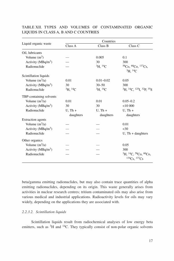
beta/gamma emitting radionuclides, but may also contain trace quantities of alphaemitting radionuclides, depending on its origin. This waste generally arises fromactivities in nuclear research centres; tritium contaminated oils may also arise fromvarious medical and industrial applications. Radioactivity levels for oils may varywidely, depending on the applications they are associated with.
2.2.3.2. Scintillation liquids
Scintillation liquids result from radiochemical analyses of low energy betaemitters, such as 3H and 14C. They typically consist of non-polar organic solvents
17
TABLE XII. TYPES AND VOLUMES OF CONTAMINATED ORGANICLIQUIDS IN CLASS A, B AND C COUNTRIES
Liquid organic wasteCountries
Class A Class B Class C
Oil, lubricantsVolume (m3) — 0.005 0.1Activity (MBq/m3) — 30 300Radionuclide — 3H, 14C 58Co, 60Co, 137Cs,
3H, 14CScintillation liquids
Volume (m3/a) 0.01 0.01–0.02 0.05Activity (MBq/m3) 30 30–50 300Radionuclide 3H, 14C 3H, 14C 3H, 14C, 125I, 32P, 35S
TBP-containing solventsVolume (m3/a) 0.01 0.01 0.05–0.2Activity (MBq/m3) 30 30 <10 000Radionuclide U, Th + U, Th + U, Th +
daughters daughters daughtersExtraction agents
Volume (m3/a) — — 0.01Activity (MBq/m3) — — <30Radionuclide — — U, Th + daughters
Other organicsVolume (m3/a) — — 0.05Activity (MBq/m3) — — 300Radionuclide — — 3H, 14C, 58Co, 60Co,
134Cs, 137Cs

such as toluene, xylene and hexane, but they may also include biological compoundssuch as steroids and lipids. Radioactivity levels are typically of the order of350 MBq/m3.
2.2.3.3. Solvents
Spent solvents may arise from solvent extraction processes. The mostcommonly used extraction solvent is TBP. TBP is diluted for the extraction processusually with a light saturated hydrocarbon, often dodecane or a mixture of paraffins.A variety of organic decontamination liquids and solvents, such as toluene, carbontetrachloride, acetone, alcohols and trichloroethane, arise from various operations.Dry cleaning produces small quantities of perchloroethylene and Freon 112 waste.The gross alpha/beta activity of this waste is usually less than about 200 MBq/m3.
2.2.4. Solid waste generation
Solid waste can be segregated into two main groups: compactible, combustiblesolid waste and non-compactible, non-combustible solid waste [6–8]. Other possiblegroups may be processible (by compaction or incineration) and non-processiblewaste. The largest volume of solid waste is general rubbish, which includes protectiveclothing, plastic sheets and bags, rubber gloves, mats, shoe covers, paper wipes, rags,towels, metal and glass [6].
Segregation should be preceded by an appropriate activity measurement and bydistinguishing between waste that after decay storage can be disposed of withmunicipal refuse (i.e. waste contaminated by radionuclides with a half-life <100days) and waste that needs treatment and conditioning. Considering the relativelysmall amounts of combustible waste, compaction should be the preferred volumereduction method. Incineration is technically much more complicated and shouldonly be considered if large quantities of combustible waste can be incinerated in acontinuous manner.
Table XIII presents an estimation of solid waste generation in class A, B and Ccountries.
The typical distribution of solid waste generated in research centres is:
— 70% compressible or combustible material, such as plastic fragments, paperand cloth, small metallic or glass objects, and miscellaneous (animal carcasses,wood, etc.);
— 20% hard materials, such as metal components, coating or lining fragments anditems whose size normally calls for fragmentation;
— 10% debris resulting from plant conversion and operational incidents (concrete,soil, etc.).
18

2.2.5. Wet solid waste generation
Wet solid waste, such as spent radioactive ion exchange resins, precipitationsludges and evaporator concentrates, is generated by the treatment of aqueous wastestreams at nuclear research centres or at centralized waste processing facilities.
2.2.5.1. Spent ion exchange resins
Ion exchange media can be classified into two basic categories: inorganic ionexchangers (both natural and synthetic) and organic resins (mainly synthetic). Mostcommercial ion exchangers are synthetic organic resins typically consisting ofpolystyrene cross-linked with divinylbenzene. Spent organic and inorganic ionexchange media may require different treatment and conditioning options. Althoughregeneration of spent organic resin is possible, the preferred option is direct condi-tioning of spent resin, as regeneration results in the production of highly acidic andcaustic radioactive liquids, which may be difficult to treat [9].
2.2.5.2. Precipitation sludges
The product of treatment of liquid radioactive waste by chemical precipitationand flocculation is a sludge containing most of the radioactivity; this can vary greatlyin terms of its chemical and physical characteristics, depending on the specificprocess used (see Section 6.4). The chemical composition of the sludge differs fromthe initial waste owing to the addition of the precipitating chemicals.
2.2.5.3. Evaporator concentrates
Evaporator concentrates are produced through an evaporation process by whichthe volatile and non-volatile components of a solution or slurry are separated to
19
TABLE XIII. ESTIMATED ANNUAL RADIOACTIVE SOLID WASTE GENER-ATION IN CLASS A, B AND C COUNTRIES
Solid waste for treatment Solid waste for direct conditioning
Category Volume Total Volume Total(m3/a) activity (GBq) (m3/a) activity (GBq)
Class A 10–20 2 1–5 3Class B 50 40 5 5Class C 50–100 40–80 10 15

reduce both the waste volume and the amount of radioactivity in a liquid effluent.Evaporation is most effectively used for radioactive liquids with high concentrationsof salts or other impurities. The concentrate or bottoms product can range from 15wt% solids to a virtually dry powder or cake, depending on the evaporator type andefficiency and on the chemical composition of the waste stream.
2.2.6. Biological waste generation
Biological radioactive waste arises from biological, research andteaching/training practices. This waste includes animal carcasses, contaminated bodyfluids and animal tissues. The inclusion of materials having a biological origin clearlydistinguishes this type of waste from inorganic materials. A primary example ofbiological waste is the waste from research involving animals. All discharges (e.g.faeces, urine and saliva) from animals used in research involving radioactive materialsmust be considered to be potentially contaminated. Animal cage containers must betreated as contaminated until monitored and declared free from contamination [10].
2.2.7. Medical waste generation
Medical radioactive waste may be defined as radioactive waste arising fromdiagnostic, therapeutic and research applications in medicine. In addition to beingcontaminated by radioactivity, medical waste, like biological waste, can have infec-tious, pathological and other hazardous properties. In many instances the potentialadditional hazard, either from the waste’s chemical, biological or physical properties,is greater than the radiological hazard [2].
The following types of radioactive waste may occur as a result of the use ofradionuclides in medicine:
— Spent radionuclide generators and spent sealed radiation sources;— Anatomical and biological waste (e.g. body parts, tissues, organs, fluids and
excreta from patients administered with radionuclides);— Miscellaneous aqueous and organic liquids, and radioactive solutions;— Miscellaneous solid dry waste (e.g. gloves, paper tissues and equipment parts);— Miscellaneous waste posing a puncture hazard (e.g. needles, broken glass and
nails).
20
3. WASTE CLASSIFICATION
3.1. GENERAL CONSIDERATIONS
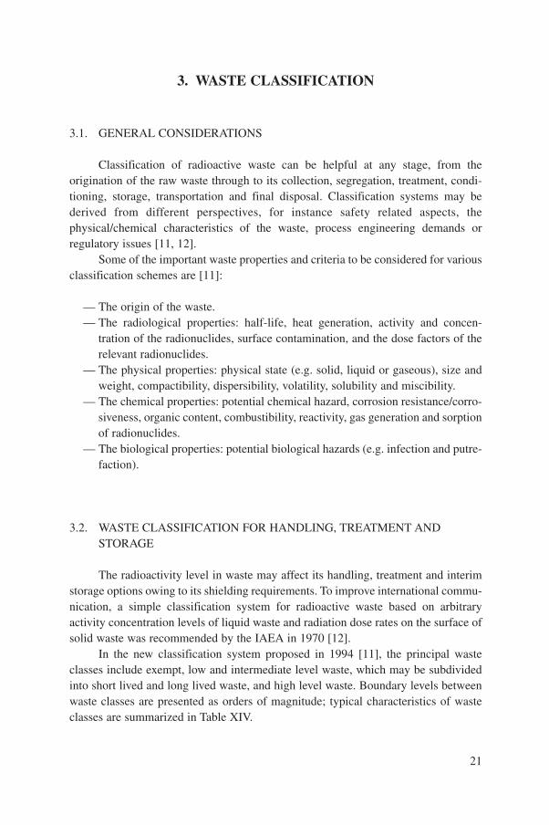
Classification of radioactive waste can be helpful at any stage, from theorigination of the raw waste through to its collection, segregation, treatment, condi-tioning, storage, transportation and final disposal. Classification systems may bederived from different perspectives, for instance safety related aspects, thephysical/chemical characteristics of the waste, process engineering demands orregulatory issues [11, 12].
Some of the important waste properties and criteria to be considered for variousclassification schemes are [11]:
— The origin of the waste.— The radiological properties: half-life, heat generation, activity and concen-
tration of the radionuclides, surface contamination, and the dose factors of therelevant radionuclides.
— The physical properties: physical state (e.g. solid, liquid or gaseous), size andweight, compactibility, dispersibility, volatility, solubility and miscibility.
— The chemical properties: potential chemical hazard, corrosion resistance/corro-siveness, organic content, combustibility, reactivity, gas generation and sorptionof radionuclides.
— The biological properties: potential biological hazards (e.g. infection and putre-faction).
3.2. WASTE CLASSIFICATION FOR HANDLING, TREATMENT ANDSTORAGE
The radioactivity level in waste may affect its handling, treatment and interimstorage options owing to its shielding requirements. To improve international commu-nication, a simple classification system for radioactive waste based on arbitraryactivity concentration levels of liquid waste and radiation dose rates on the surface ofsolid waste was recommended by the IAEA in 1970 [12].
In the new classification system proposed in 1994 [11], the principal wasteclasses include exempt, low and intermediate level waste, which may be subdividedinto short lived and long lived waste, and high level waste. Boundary levels betweenwaste classes are presented as orders of magnitude; typical characteristics of wasteclasses are summarized in Table XIV.
21

3.3. CLASSIFICATION FOR RELEASE FROM REGULATORY CONTROL
3.3.1. Exemption and clearance concept
The concept of exemption (or clearance) was pursued for several years throughIAEA working groups under a general concept of ‘de minimis’, mainly in relation toradioactive waste disposal in marine and terrestrial environments [14, 15]. In 1984, inco-operation with the Nuclear Energy Agency of the Organization for Economic Co-operation and Development (OECD/NEA), a new programme was started with thespecific objective of (a) developing principles for exempting radiation sources andpractices from regulatory control and (b) developing guidance on the application ofthe principles to practical problems. This culminated in 1988 with the publication ofSafety Series No. 89 [16], which contains results representing an internationalconsensus on the subject.
Some types of sources of ionizing radiation may not be subject to regulatorycontrol, either because they are not amenable to such control and therefore excludedfrom the regulatory process or because they present such a low risk that control by
22
TABLE XIV. TYPICAL CHARACTERISTICS OF WASTE CLASSES
Waste class Typical characteristics Disposal options
1. Exempt waste (EW) Activity levels at or below the clearance No radiological levels given in Ref. [13], which are restrictionsbased on an annual dose to members of the public of less than 0.01 mSv
2. Low and intermediate Activity levels above the clearance levels Near surface or level waste (LILW) given in Ref. [13] and thermal power geological disposal
below about 2 kW/m3 facilities2.1. Short lived waste Restricted long lived radionuclide Near surface or
(LILW–SL) concentrations (limitation of long geological disposal lived alpha emitting radionuclides facilitiesto 4000 Bq/g in individual waste packages and to an overall average of 400 Bq/g per waste package)
2.2. Long lived waste Long lived radionuclide Geological disposal (LILW–LL) concentrations exceeding the facilities
limitations for short lived waste3. High level waste Thermal power above about 2 kW/m3 Geological disposal
(HLW) and long lived radionuclide facilitiesconcentrations exceeding the limitations for short lived waste

regulatory processes would be a waste of resources. In the latter case, two categoriescan be distinguished:
— Radiation sources which never enter the regulatory regime, that is control is notimposed;
— Radiation sources which are released from regulatory control, that is control isremoved.
Sources in the first category are excluded from regulatory control by a processcalled exemption. The corresponding levels of activity or activity concentration arecalled exemption levels. In the second category the release of sources from control iscalled clearance. The amount of material involved in clearances can be substantialand is generally greater that those involved in exemptions. The corresponding levelsof activity or activity concentration are called clearance levels. The distinctionbetween exemption and clearance in IAEA publications has been made only recently[17], and so in the literature terms such as exemption and exempt are often used incircumstances where terms such as clearance and cleared would currently be used.
The IAEA has recently published reports dealing with the problems involved inapplying exemption principles to waste arising from the use of radionuclides inmedicine, industry and research [17]. In these publications methods for derivingexemption levels (clearance levels) are described and examples for calculating theselevels are given.
Various national and regional groups have also been studying exemptionprinciples and their application. National regulations have been developed in variouscountries based on these international guidelines, and recommendations have beenmade on applying then to local conditions. Thus a substantial base of experience nowexists; clearance levels have been proposed in various countries for application to themost important low level waste streams from the nuclear fuel cycle and from theapplication of radioisotopes in medicine, research and industry.
3.3.2. Requirements for release to the environment under authorization
Before attempting to select and design a waste treatment system the restrictionsor limits on releasing liquid and gaseous waste effluents need to be understood.Determination of these limits is performed differently in various countries, but alwaysrequires an extensive analysis by both the waste producer and regulatory body to arriveat an agreement that releases are acceptable. The basic principles for establishing releaselimits are set out in IAEA Safety Series Report No. 77 [18]. Essentially, this states thatpractices involving a release of radionuclides to the environment should be optimized;that is, that the associated radiation doses to the public and to workers should be as lowas reasonably achievable (ALARA), and that doses should be below specified limits.
23

The evaluation of these radiation doses may involve the use of environmental models inwhich the transport of radionuclides to humans through the processes of atmosphericdispersion, deposition and movement through terrestrial and aquatic systems and foodchains is represented. The limitation of doses to members of the public is achieved bylimiting the dose to an identified critical group; that is, a group of persons who, by virtueof their location, habits, etc., are representative of those most highly exposed in thepopulation. This modelling is generally referred to as pathway analysis.
The International Committee on Radiological Protection (ICRP) prescribesdose limits, but since an individual may be exposed to more than one source ofradiation only a fraction of the whole dose limit should be assigned to any givenpractice. In its most recent recommendations [19] the ICRP introduced the term doseconstraint as the fraction of the dose limit that may be applied to a single practice.The dose constraint should be used as the upper bound for the optimization process.The values of the dose constraint should be set by national authorities.
There may be several different options for managing a waste stream, each ofthem involving some discharge to the environment, for example direct discharge,discharge after treatment and discharge after storage. Some of the options initiallyconsidered may be discarded for non-radiation protection reasons, for example ongrounds of cost or for operational reasons, or for the control of other chemical orbiological hazards.
Once an agreement has been reached as to the suitability of a proposed wastetreatment scheme, a discharge authorization should be provided by the nationalauthority to the waste producer; this should detail the specific requirements to be metat the point of discharge in terms of:
— The maximum permissible radioactivity concentration in the effluent;— The flow rate of the effluent and total volume;— The daily, monthly and/or yearly radioactivity discharge levels both for total
activity and for individual or groups of radionuclides.
3.4. CLASSIFICATION FOR WASTE DISPOSAL
For radioactive waste that cannot be released to the environment, specialdisposal facilities (repositories) must be provided. For radioactive waste disposal themost important radiological classification parameter is the concentration of long livedradionuclides, especially of alpha emitters [20]. The new waste classification systemproposed by the IAEA considers a qualitative classification for radioactive waste[11]. The proposed categories take account of properties such as half-life and heatgenerating capacity. The categorization, shown in Table XIV, assumes that the wastehas been appropriately conditioned and packaged.
24

Requirements for class 1 waste, exempt waste, are described in Section 3.3.Class 2 waste is suitable for shallow ground disposal as it has insignificant alphaactivity and heat output, and intermediate and low radiotoxicity. With the exceptionof spent sealed sources, wastes generated in developing countries are essentiallywithin these two categories. For radioactive waste containing more than a specifiedamount of long lived radionuclides, significant engineered facilities (e.g. deepgeological repositories) are required.
Many developed Member States have quantitative regulations classifying theirwastes [21, 22]. The regulations usually apply restrictions on the concentration ofradionuclides in individual packages and in the waste as an average. The values aredetermined by means of a safety assessment in which the scenarios and routes bywhich humans could be exposed during the operation of a repository and after itsclosure are analysed. It is not usually considered possible to give general values forgamma/beta emitters as they vary, depending on the characteristics of the disposalsite. However, the limiting values for alpha emitters are less variable, and these valueshave been published [22].
4. COMPONENTS OF A COMPREHENSIVE WASTEMANAGEMENT SYSTEM
Member States, especially those that have already established nuclear researchcentres that produce radionuclides for medical and research purposes, need toestablish a national waste management policy and a systematic national wastemanagement programme. A national waste management programme should includeat least the following elements:
— Development and adoption of appropriate legislation and regulations [23–25];— Effective planning, implementation and enforcement procedures;— The provision of adequate facilities for radioactive waste management;— Appropriate training plans for national enforcement officers, plant operators
and managers; — Public awareness education programmes.
4.1. NATIONAL POLICY
A national policy for radioactive waste management is a fundamental corner-stone of a radioactive waste management system [23]. The roles and responsibilitiesof the organizations involved in its implementation should be clearly identified and
25

the necessary resources (organizational, financal, technical and advisory) should beprovided to administer the policy.
The national waste management policy should be expressed so as to protectpeople and their environment from undue exposure to ionizing radiation fromradioactive waste by the application of up to date internationally accepted wasteprocessing recommendations and safety requirements. In establishing and keepingthe policy and programmes under review, governments should be advised by appro-priately qualified persons whose combined expertise covers all relevant disciplines.Ideally, these advisors should be independent of the waste generators and operatorsof waste management facilities.
While the national policy should be created based on internationally acceptedscientific principles, it should also consider local social conditions or cultural valuesand traditions. The national policy should generally be established at the highest levelof government, usually at the national executive level. Recognizing that governmentscan change, or change direction very quickly, the national policy should be insulatedas much as possible from frequent political and bureaucratic changes. Failure toprovide such political insulation will result in an unstable regulatory environment thatmay compromise the overall effectiveness of the waste management programme. Thenational policy should also be adaptive, so that it can be applied to new circumstancesor modified if legitimate reasons emerge for doing so. It should be proactive, ratherthan reactive.
The national waste management policy should form the basis for legislation andregulation of waste management activities. The policy may state preference for onemanagement option over another (e.g. storage for decay then disposal as non-radioactive waste, versus immediate disposal as radioactive waste) and define thefunding and management responsibilities for the programmes and the legal/jurisdic-tional roles for various government departments.
4.2. LEGISLATION AND REGULATIONS
Waste management legislation should be introduced together with generalradiation protection, nuclear energy or other relevant national legislation (e.g. forindustrial safety and environmental protection). To achieve acceptance by a majorityof the population, the waste management legislation should be constructedaccording to the national legal, technical and cultural traditions. It may be periodi-cally reviewed and modified as a result of changes in the national waste managementpolicy.
Waste management regulations should generally be drafted by the appointedregulatory agency, based on the national policies and legislation. Following modifi-cation, approval and enactment by the appropriate assemblies, the legislation should
26

form the basis for the regulations. The legislation can establish definitions, listtechnical limits on various waste properties and/or quantities (or specify the processto establish them), and establish legal mechanisms for enforcement, exclusion orexemption for various forms of waste.
Documented enforcement procedures should be formally created by theregulatory agency based on the legislation and regulations. These procedures, used byregulatory officers, need to ensure consistent application and interpretation of theregulations. It is also important to maintain a record of previous decisions and inter-pretations so that these can be consistently applied in the future.
National legislation is of no practical value if it does not have an organizationwith enough resources for its implementation. Enforcement of the legislation andregulations should be carried out by a regulatory body, which should have theauthority to impose sanctions or to suspend operating licences if serious violations ofthe law or regulations are made by the operators.
4.3. WASTE MANAGEMENT FACILITIES
4.3.1. General
It is the responsibility of the regulatory body to ensure that licence holders haveall the necessary equipment for waste processing and site/environment monitoring,and that it is suitable for the licensee’s purpose. The implementation of a wastemanagement programme in compliance with national policy and established regula-tions requires adequate technical capabilities; these include facilities, installationsand personnel. The facilities should be constructed to comply with the specificrequirements, existing or foreseen, for local or national waste management.
Since many individual producers of waste may not have sufficient interest orexpertise in waste management, it may be appropriate to consider having a centralwaste management facility where the necessary expertise, infrastructure and qualityassurance capability can be built up. Accordingly, this concept envisages that wastefrom a variety of producers will be transported to the central facility for subsequentmanagement. In many countries the national nuclear research organization will be thecentral agency responsible for radioactive waste management, with regulationprovided by an appropriate government department.
The impact on waste management facilities from planned changes in the use ofradionuclides, notably an increased usage or new applications, must be analysed andall necessary modifications implemented or required new facilities made ready in atimely manner to comply with the changed requirements when they occur. In order tomanage short term increases in waste volumes to be processed, for example as a resultof an incident, the capacity of facilities should be higher than required for normal
27

operation. The extent of the increased capacity should be based on an optimization ofwaste treatment methods, efficiencies and radiation protection. It should be theresponsibility of the user to provide it, and of the regulatory body to determine that itis adequate for its purpose. Often a regulator will require, as part of the licensingconditions, the operator of a facility to maintain a minimum reserve capacity emptyat all times to cover emergency requirements.
The waste management facility should secure for itself the best equipmentavailable. This, however, does not mean that the most expensive and sophisticatedequipment should be procured; in most cases it is preferable to have less sophisticatedand less costly equipment but which is reliable and performs its required functionsadequately. Such factors as service and maintenance facilities, the availability ofspare parts, etc., should also be considered.
The waste management facility should determine the location of equipment thatmay be needed in emergencies and ensure that it is readily available. Examples ofsuch equipment are additional radiation protection monitors, shielded transportcontainers, decontamination equipment and remote handling devices.
The central facility must have the necessary financial resources for the safemanagement of the waste; this should be considered during the initial stages ofplanning for the use of radionuclides. The government should also ensure by appro-priate means that money for the safe management of radioactive waste is available forsituations when an operator, for whatever reason, no longer has the financialresources properly to handle radioactive waste.
4.3.2. Planning considerations
Planning, implementing, managing and enforcing a waste managementprogramme requires careful thought. Several factors must be taken into consideration:
— Care should be taken to minimize risk both to the natural environment and tothe public.
— Where it is not yet possible to undertake all of the management steps fromwaste origination to final disposal, it is advisable that steps be taken to avoidclosing off later options, since some may require substantial additional cost andradiation dose penalties.
— If the dilute and disperse option open for some aqueous and gaseous wastes isnot appropriate, strategies incorporating confinement and concentration of thewaste should be considered.
— The preferred processes should be considered taking into consideration thelocal availability of equipment and resources. This is especially true in devel-oping countries, where highly sophisticated equipment may be difficult toobtain and maintain in a proper working condition.
28

— Following immobilization, a complete waste management strategy shouldinclude both storage and disposal. However, in developing countries thequantities of waste for disposal may not be sufficient to justify construction ofa waste repository. Consequently, the conditioned waste may have to be storedfor an extended period of time.
The overall waste management scheme should be properly planned to considercollection and segregation of wastes, their volume reduction and appropriate condi-tioning into a form suitable for future handling, transportation, storage and disposal.Pertinent technological steps in managing radioactive waste are detailed in Fig. 1.
4.3.3. Waste minimization
Minimization of radioactive waste generation is a vital requirement that mustbe addressed at all stages of the design and operation of facilities that use orproduce radioactive materials.Waste minimization generally encompasses three mainareas [26]:
— Source reduction, which includes any activity that reduces or eliminates thegeneration of radioactive waste within a process (including segregation of wasteand prevention of contamination spreading);
— Recycling and reuse of valuable materials produced as by-products of theprocess;
— Treatment to reduce the volume of a radioactive waste without recovery orreuse of the material.
Of these three concepts, source reduction is generally the most important inclass A, B and C countries.
To facilitate subsequent handling, treatment and storage, it is strongly recom-mended that waste be segregated at the place of origin. It is essential to segregateinactive waste from active waste and to isolate low specific activity waste and thatcontaining short half-life radioisotopes from that requiring further treatment.
4.3.4. Pretreatment
Segregation is one of the most important pretreatment methods in managingwaste originating in class A, B and C countries. The collection of waste shouldprovide for segregation according to half-life and chemical composition in order tofacilitate subsequent storage for decay, or treatment, conditioning and disposal.
Waste containing long lived radionuclides generally requires a more complextechnological infrastructure. Waste treatment, conditioning, storage and eventual
29

disposal may all be required, and in turn will require appropriate facilities, equipmentand training of personnel.
Further details of pretreatment techniques and practices can be found inRef. [27].
4.3.5. Treatment
Treatment of waste involves operations intended to benefit safety and/oreconomy by changing the characteristics of the waste. The waste volumes in class A
30
Waste generation
Minimization Collection Pretreatment Segregation
Short lived Long lived
Volume Treatment reduction
Immobilizationand packaging
Conditioning
Storage Interimstorage
Storage for decay
Shipment Transportation
Disposal
Sewer Landfill Near surface Underground or stack repository repository
FIG. 1. Technological steps for managing radioactive waste.

countries are usually small and do not require any special treatment. For class Bcountries simple compaction equipment may be sufficient for solid low level waste,whereas liquid waste can either be stored for decay or directly solidified. In the caseof class C countries solid waste may be treated by compaction or incineration, andliquid waste concentrated by means of chemical precipitation, evaporation or ionexchange techniques.
4.3.6. Conditioning
It is generally agreed that the safe management of radioactive wastes may bebrought about if they are transformed into a solidified form through an appropriateconditioning technique. Conditioning of waste is defined as those operations thatproduce a waste package suitable for handling, transportation, storage and/ordisposal. Conditioning may include the conversion of the waste into a solid wasteform, enclosure of the waste in containers and, if necessary, providing an overpack.In the case of class B countries simple equipment operated on a laboratory or pilot plant scale will be sufficient to condition small amounts of liquid waste forstorage and/or disposal. Class C countries may require a small dedicated facility for the treatment of liquid waste and for the conditioning of concentrates and spent ion exchange resins from research reactor operations and various other appli-cations. These operations, which involve immobilizing radioactive waste andproviding adequate packaging, are mainly based on the use of cementation, althoughthere are also other appropriate immobilization methods, as described in Sections 9and 10.
4.3.7. Storage
All class A, B and C countries require storage facilities to accommodate wastearisings prior to their release or disposal. Two types of waste storage may be required:
— For raw waste awaiting treatment or decay for release,— For conditioned waste awaiting disposal.
Only simple storage facilities, such as a separate room or part of a room withina hospital or research complex, are required in class A countries; more complicatedstorage facilities may be needed in class B and C countries. Storage facilities shouldbe well constructed, with inner surfaces that can be easily decontaminated, andprovided with security measures to prevent the intrusion of unauthorized persons. Inaddition, storage facilities in class C countries accommodating long lived wasteand/or spent fuel may need additional provisions, such as dosimetric control andventilation [28].
31

4.3.8. Transportation
In countries where the movement of waste to a centralized site is practiced,special attention needs to be paid to transportation. The waste packages, means oftransportation and overall transport conditions should meet the requirements set forthin the internationally accepted IAEA regulations [29]. This also applies for the trans-portation of spent sources back to the supplier, and of packaged waste for disposal ina regional or national repository.
In many cases, where the amount or activity of the waste is low, there is noobligation to use a specifically designed vehicle for transportation. However, fortransboundary movements of radioactive materials, the need for special agreementsmay arise.
4.3.9. Disposal
Disposal of radioactive waste involves placing it in an approved, specifiedfacility (e.g. a near surface or geological repository) without the intention of retrieval.Disposal may also include the approved direct discharge of effluents (e.g. liquid andgaseous waste with very low activity) to the environment, with subsequent dispersion.For countries with minimum waste quantities originating from few practices, it maybe inappropriate to construct and operate a national repository. It should be noted thatwhen sealed sources are originally supplied by a foreign vendor, return of the spentsource to the original country of supply is the best solution.
In the case of class A and B countries, disposal options may include landfill ofshort lived low level waste. For long lived spent sources, notably 226Ra, that cannotbe returned to the vendors, as well as other conditioned wastes with activity contentsexceeding the criteria for disposal in a national near surface repository, controlledstorage is presently the only practicable option. Geological repositories for thesewaste categories are being developed in several countries, but would possibly not bejustified in terms of cost for non-nuclear power countries with only modest amountsof waste. The long term solution for such countries may involve international co-operation in geological disposal [30, 31].
4.3.10. Documentation
A well designed waste management strategy enables an establishment to keeprecords that integrate and document the information obtained in all phases of wastemanagement. Full traceability of waste up to the stage of storage or disposal isessential. A key step for such a strategy is that an appropriate description of the wasteis available when it is collected at the point of origin. This essential information canbe most conveniently collected by the use of appropriate labels affixed to the waste
32

packages or containers (for examples see Fig. 2). The documentation requirementsand level of detail are normally specified by the national regulations.
33
FIG. 2. Typical information labels.

4.4. CONSIDERATIONS FOR A COST EFFECTIVE SYSTEM
Although the basic principle should be that waste generators bear the costsincurred by their activities, the responsibility for ensuring the necessary financialresources for the execution of waste management programmes rests with the state.The financial requirements broadly comprise two categories. The first category coversthe direct costs involved in carrying out the various operational steps such ashandling, transport, conditioning and storage. These costs can be allocated to therespective waste generators and operators. The second category covers the indirectcosts, such as those of the state and regulatory functions.
Any waste management plan should include cost estimates to be used forforming the basis for funding proposals consistent with the national wastemanagement system, and that describe a financing mechanism using the provisionsincluded in the legal framework of the country. This financing mechanism couldprovide means to allow the charges borne by some categories of waste generators,such as hospitals, universities and research institutes, to be subsidized.
5. STORAGE OF UNCONDITIONED WASTE
5.1. GENERAL REQUIREMENTS
Waste storage facilities for unconditioned liquid and solid radioactive wastemust provide the following [28]:
— Operational convenience, for example allowing the accumulation of waste so asto facilitate the more cost effective use of treatment facilities, transportation anddisposal routes;
— Safe and secure retention during a period long enough to permit radioactivedecay prior to further radioactive waste management steps, for example storingshorter lived contamination in untreated waste prior to its disposal or dischargewithin exemption or clearance limits authorized by the national regulatoryorganization;
— Efficiency of the storage operation, with segregation of different wastecategories, record keeping and easy retrieval permitting efficient furthermanagement of the waste;
— Verification and/or checking of individual packages.
34

5.1.1. Storage at radioisotope user establishments
Unconditioned waste is likely to be stored initially in the establishment whereit is created. The waste must be segregated there and prepared for decay and/or furthertreatment or transportation in accordance with the acceptance criteria of thecentralized radioactive waste management facility to which it may be subsequentlytransferred, or for disposal according to the selected route.
At the user establishment the storage requirements can be fulfilled in storesappropriate to the type of operation involved, normally in simple storage areasranging from single secure cabinets or lockable wheeled bins to one or morededicated rooms. Efficient operation of the store is essential to avoid the unnecessaryaccumulation of waste in work areas. This necessitates a planned system of collectionand transfer of waste to the store in a well documented orderly fashion, and keepinginformation to be used for future management. All waste should be segregated andaccumulated in containers that are suitable for further safe handling in line with futuremanagement proposals, taking into account factors such as robustness or biodegrad-ability of containers, as required.
5.1.2. Storage at radioisotope production facilities
Generally, in routine radioisotope production facilities limited storage of liquid and solid waste is incorporated as part of the plant’s design. Quantities of up to intermediate level waste will arise that will require local storage for decay of the predominantly short lived contaminants, before handling and transfer fortreatment or disposal. Larger radioisotope producers need to install special storage facilities adjacent to the hot cells. Solid waste arising from radioisotopeproduction may require several months of decay storage prior to release or furtherprocessing.
5.1.3. Storage at research reactors
In developing countries most reactor facilities have some waste storagearrangements integrated into their original design. Cleanup of the primary circuitcooling water using normal ion exchange processing gives rise to a small amount ofwaste requiring treatment and conditioning.
If the reactor cooling water is treated by the ion exchange process withoutregeneration, then the spent ion exchange media is likely to be radioactive wasteapproaching the intermediate activity level, which requires remote handling,shielding or in situ decay storage before manual handling. When the ion exchangemedia is regenerated, the small proportion of liquid waste containing the majority ofthe activity should be stored for subsequent treatment.
35

5.2. SPECIFIC REQUIREMENTS FOR THE STORAGE OF BIOLOGICAL ANDMEDICAL RADIOACTIVE WASTE
Storage of unconditioned biological and medical waste often necessitates lowtemperature refrigeration, with temperatures typically –18 to –22°C. For prolongedstorage at a centralized radioactive waste management facility beyond two or threeyears the waste should be stored at –70°C to minimize low temperature putrefaction.
Specific requirements for the refrigerated storage of unconditioned biologicaland medical wastes includes:
— Consideration of offensive odours from unconditioned waste, such as those thatarise from food waste (e.g. from patients treated with therapeutic levels ofradioiodine).
— Control of insects and rodents, which can present a serious threat to thecontainment of unconditioned packages of radioactive biological waste. Theconsumption of waste and dispersion through insect/rodent excretions canresult in the spread of both radioactive contamination and potentially infectiousmaterials.
— Ease of closure/sealing of the radioactive waste packages to preventdispersion/seepage of contents.
— Ability of the packaging to withstand, without deterioration, the full range oftemperature variations it is likely to encounter, such as the ability to withstandfreezing without becoming brittle and liable to fracture.
Considerations for the design of organic liquid storage facilities includechemical hazards, fire protection, containment of spills and control of ventilation toprevent the buildup of harmful vapours.
5.3. DECAY STORAGE
When possible, and if permitted by the non-radioactive risks, advantage shouldbe taken of the opportunity to avoid treating radioactive waste by carefully organizingthe decay storage of shorter lived contaminated waste. Volatile or combustible wastepresenting a hazard through fire, biological instability or toxicity are the main riskfactors to be taken into consideration.
Decay storage for the common short lived radioisotopes is normally routinelyapplied to segregated low level waste from radionuclide users in hospitals, univer-sities, research laboratories and other institutions. At radioactivity concentrations of3.7 to 37 MBq/m3 (0.1 to 1 mCi/m3), decay storage of ten half-lives (giving a
36

reduction of greater than 1000) potentially reduces the residual radioactivity contentto below the limits for unconditional release/disposal.
Table XV gives the times (in years) for reduction in activity by factors of 10 to106 for commonly used short lived radionuclides. Large reduction factors areachieved within short periods for very short lived radionuclides (e.g. a factor of 106
in five days (1.4 × 10⁻² a) for 99Tcm). For such short lived radionuclides there are notlikely to be problems with discharge limits at the clearance level. Very short storageperiods provide adequate decay, even at the lower limits for clearance. Problems arisefor radionuclides with half-lives of between about six weeks to one year, but theactivity reduction required is also a factor to be considered. For 45Ca, of half-life 0.45years, a period of nine years is required for a 106 reduction. Storage over such a longperiod may not be judged appropriate because of the risks associated with the longinterim storage period.
The practical implementation of decay storage requires the operation of aprotected, selective storage capacity with matching identification and other adminis-trative procedures. This ensures that packages are stored for the correct length of timeand the correct package is retrieved for disposal. Usual radiological protectionrequirements should apply regarding the handling of active or potentially activematerials, even in the simplest facility.
The containers used for storing unconditioned waste are normally reusable200 L drums with a lid firmly held in place by a metal clamp. The inner coating ofthe drum is suitable for cleaning with disinfectant or decontamination solutions.
Table XVI illustrates the records that may need to be maintained for radionu-clides placed in decay storage. Completion of the records involves consideration ofthe features of the waste. At the time of receipt the duration for decay storage shouldbe evaluated. In using the example given in Table XVI and consulting Table XV, after47.5 days (1.3 × 10⁻¹ a) the waste will be below 100 kBq/kg (with a mass of 1 kg thetotal activity is therefore 100 kBq) and thus will have a total activity less than 370kBq. Assuming 32P is of moderate radiotoxicity then, after this time, the waste willconform to the exemption criteria given in Section 3.
This is only an example application of storage for decay criteria. Any realcalculation would also need to take account of specific national criteria andregulations.
5.4. DESIGN FEATURES FOR AN INTERIM STORAGE FACILITY
5.4.1. General
Developing Member States will not usually require a substantial separatebuilding as a store for untreated waste. However, in the event of a backlog and no
37

38
TABLE XV. TIMES FOR SELECTED RADIONUCLIDES TO DECAY TO SPECIFIED LEVELS
Decay Time a (in years) for reduction in activity by a factor of:Radionuclide constant
(a–1) 10 102 103 104 105 106
32P l.8 × 10 1.3 × 10⁻¹ 2.6 × 10⁻¹ 3.9 × 10⁻¹ 5.2 × 10⁻¹ 6.5 × 10⁻¹ 7.8 × 10⁻¹
45Ca 1.5 1.5 3 4.5 6 7.5 999Mo 9.2 × 10 2.5 × 10⁻² 5.0 × 10⁻² 7.5 × 10⁻² 1.0 × 10⁻¹ 1.25 × 10⁻¹ 1.5 × 10⁻¹
99Tcm 1.0 × 10³ 2.3 × 10⁻³ 4.6 × 10⁻³ 6.9 × 10⁻³ 9.2 × 10⁻³ 1.2 × 10⁻² 1.4 × 10⁻²
125I 4.1 5.6 × 10⁻¹ 1.1 1.7 2.3 2.8 3.4131I 3.2 × 10⁻¹ 1.7 × 10⁻¹ 3.4 × 10⁻¹ 5.0 × 10⁻¹ 6.7 × 10⁻¹ 8.4 × 10⁻¹ 1.0192Ir 3.4 6.8 × 10⁻¹ 1.36 2.0 2.7 3.4 4.1
a Note: The above table is calculated from the following formula:
where T is time in years; l is the decay constant; R is the reduction factor in 10n; ln is the natural logarithm (Naperian).
ln RT = ____
l

39
TABLE XVI. EXAMPLE OF A DECAY STORE RECORD
WasteDate for disposal as
itemDate
RadionuclideActivity
DescriptionStorage exempt waste or Disposal
numberreceived at receipt location cleared waste; completed
disposal route
1 1 July 1990. 32P 1 MBq Contaminated cotton Bay 1, 1 Sept. 1990 to Signature of Signature swabs and plastic aisle A, municipal tip store manager;of store sealed in a plastic location 2 datemanager container, mass 1 kg
approx.
2 Etc.

waste treatment plant being constructed, it may be necessary to provide for a separatestorage facility.
Temporary storage of untreated/unconditioned waste can on occasion be basedon a compromise between the rooms in existing facilities and the construction of aseparate building. The use of converted marine shipping International Organizationfor Standardization (ISO) standard containers as a storage facility foruntreated/unconditioned waste has been found to offer a simple solution to suchstorage requirements [28]. ISO containers have the advantage that they are low cost,readily available, lockable, stackable and designed to withstand severe weather andwater ingress from normal precipitation.
If a treatment and conditioning process cannot be installed to avoid the need forstorage capacity in a separate building, the design features should be extended toinclude the following.
— The radioactive waste solids should be stored tidily and placed in drums,bins, racks, pallets or skids suitably planned for minimum handling; thisminimizes the risk of the spread of contamination. Aisles should be at least one metre wider than the widest loaded device or vehicle, and account should be made of vehicle turning circles; this minimizes the risk of damaging, toppling or waste containers breaking open when moving throughthe aisles.
— Shielding should be provided so that the radiation dose rate at any accessibleposition outside the store does not exceed locally prescribed levels, which aretypically of the order of 0.7 mSv/h. Data for shielding from gamma radiationby various materials are provided in Ref. [32]. Shielding for radioactivesubstances should take account of scattered radiation and source distribution.
— Storage of flammable or toxic liquids or solids should be in a separate area ofthe building provided with fire resistant storage cabinets and spark resistantlighting. Fire fighting equipment and a fire detection system will also berequired.
— Care should be taken if there is a regular turnaround of particular types of wastepackage; arrangements should be made for a first in, first out receipt/dispatchsystem to prevent the potential for inadvertently storing some packages for verylong periods or, more importantly, not storing some for long enough.
— Storage capacity should be adequate to house the expected waste throughput.— Access must be designed to be secure, with possible automatic restriction to
authorized personnel only. Personal and vehicle radiation monitoringequipment should be installed at exit points.
— The store design should take adequate account of the risk of accidents of bothinternal or external origin, such as flooding, gales or other severe weather,depending on the location.
40

5.4.2. Additional design features for liquid waste storage
Collection and storage of radioactive liquid waste should involve the use ofapproved containers for small quantities of liquid waste and tanks for larger amounts,with provision made for:
— Operational control,— Collection and interim storage before treatment of a batch,— Activity decay storage,— Monitoring.
For obvious safety reasons liquid wastes requiring transfer from a containershould not be poured. The design of the installation should include suitable liquidtransfer piping and equipment such as leak proof pumps.
Waste in a particular store should be selected for chemical compatibility andsuitability for long term retention. Consideration should be given to the provision ofa ventilation system together with, if necessary, air monitoring of the storagebuilding. If local climatic conditions are severe this may need to include forced circu-lation, with heating or cooling and conditioning of the inlet air as appropriate, toavoid extreme temperatures or high humidity conditions.
Small quantities of liquid waste should be absorbed in a suitable material, such assawdust, before storage. When more active liquid waste is stored it should often be placedin a secondary container or, when small volumes are involved, on a tray large enough tocontain the liquid if the primary container starts leaking during storage. Small volumesof organic scintillant should be accumulated in small vials and tubes bulked in hermeti-cally sealed polypropylene containers, with the overall liquid volume restricted to either1 or 5 L per container (for scintillants with flash points of 21°C or 150°C, respectively).
The design of bulk liquid storage systems for centralized waste treatment plantsis evaluated in detail in another IAEA report [1], but the following factors must betaken into account:
— The volumetric and activity inventory and the nature of the liquids to be stored(e.g. corrosive, aqueous or organic);
— The construction constraints, materials and fabrication standards;— The shielding safety and containment requirements;— The accessibility for maintenance and remedial action;— The availability of sampling systems.
Agitation and homogenization of the contents are frequently required and maybe achieved by recirculation using a discharge pump, although stirrers or otheragitators may be used.
41

Primary containment may be provided by the storage vessels and secondarycontainment by the storage cell or structure (for low level waste that is epoxy paintedor lined, concrete or fired brick cells may be adequate). Level gauges and alarms mustbe considered. For any alpha active liquids, a secondary containment may be providedby well constructed gloveboxes. Any leak from a storage tank and its associatedpiping and fittings needs to be detected and the leak retained by local containment.Sump tanks and transfer devices may be necessary.
Store buildings and their internal surfaces and contents should be constructedwith a smooth and impervious finish to allow effective decontamination.
Under certain conditions, waste may generate flammable gases owing toradiolysis or chemical reactions. Depending on the probability of this happening andits probable severity, there may hence be a requirement for the installation of instru-mentation systems to detect the buildup of flammable gases, and inert gas or other firesuppression systems. Such systems must be designed to prevent a discharge whilepeople could be in the area, since the gases may cause asphyxiation.
5.5. OPERATING PROCEDURES
5.5.1. Receipt phase
The waste acceptance criteria issued to the producer needs to identify the infor-mation that the store manager requires to permit acceptance of a waste package intothe store. Once completed by the waste consignor, the store manager should examinethe information to confirm that the waste is acceptable for storage; for example, he orshe should check that the correct packaging standard is used and that radiation levelsare within acceptable limits. If the waste is unacceptable, the details need to berecorded and the documents returned to the consignor with an explanation or requestfor further information.
On acceptance, the equipment required for transfering the waste (e.g. a forklifttruck) to the store should be selected and the store operator should prepare the appro-priate documentation required to store the waste. At the store a suitable location forthe waste should be identified and the location details recorded. The informationprovided by the consignor and the storage location of the package should be filed inthe store’s central records.
The operator of the storage facility should be trained in the appropriate methodsof radiological protection and monitoring, and in the use of the safety equipmentnecessary for handling any ‘special precaution’ waste packages.
42

5.5.2. Storage phase
The store manager should be responsible for the waste in the facility and for themaintenance of adequate conditions to allow its satisfactory continued storage,including:
—Adequate environmental conditions to avoid waste packages deteriorating;— Sufficient storage space for future arisings of waste as anticipated by the waste
consignors;— Correct and appropriate radiological protection procedures to ensure exposure
to workers and the public is kept ALARA, and that there is no contamination ofthe store or the waste packages.
The records of the store contents should be kept up to date, and there should beperiodic checking of the store contents against the records. For decay stored wastethese records should include the period of storage required and the date on which thewaste may be dispatched from the store for disposal.
An audit should be carried out at suitable intervals (e.g. quarterly) by the personresponsible for the store to account for each waste package that should be present.Radiation and contamination surveys should be undertaken to ensure that contami-nation has not occurred. The frequency of the surveys should depend upon the use,quantity and form of the substances; monthly surveys should suffice for a typicalstore. It is especially important to ensure that appropriate monitoring instruments areused. Some of the commonly used radionuclides emit only low energy radiation notdetected efficiently by Geiger–Müller tube equipment; thin window instruments orscintillator detectors may be required. Collection of smear samples with counting ina low radiation background area is required when the gamma dose rates from storedwaste exceed about 10 mSv/h.
5.5.3. Dispatch phase
Following the receipt of a request to retrieve a package from storage, the storemanager should obtain the details of the particular waste package from the store’srecords and pass them to the appropriate party. If the details are in order, the packageshould be accepted for removal from storage. Once the store manager has authorizedthe release of the waste package, the package should be retrieved from the store andtaken to the dispatch area. Here, the package should be monitored for radiation levelsbefore it is released. If the waste package is due for transport from the facility site,the details of the package should be transferred to the transportation records and thewaste packaged for transport as appropriate under established standards [29]. Thepackage’s storage records should be amended to record the date of dispatch and the
43
receiving party. Any documentation required at the final disposal location should beappropriately completed and checked at the time of the dispatch of the waste.
6. TREATMENT OF AQUEOUS WASTE
6.1. GENERAL CONSIDERATIONS
While it is expected that most low level aqueous waste may be discharged tothe environment, either directly or after a suitable decay period, a portion of the wastemay need to be treated. The treatment process selected should be based on conven-tional chemical treatment principles, but the individual characteristics and sources ofthe waste must be considered. Failure to account for the chemical and biologicalnature of aqueous waste may result in inadequate treatment and/or conditioning andcould even damage the waste processing facilities. Detailed descriptions of thevarious waste properties that are important for different treatment processes may befound in Refs [3, 33–36].
There are essentially two strategies for medical radioactive waste managementthat may be employed, dependent upon the facilities and the extent of use of radionu-clides within a country:
— An on-site waste management strategy,— A combination of an on-site and a centralized waste management strategy.
The latter may be appropriate especially in the cases of countries that producea significant amount of waste containing long lived radionuclides. A centralizedstrategy is recommended for most long lived radionuclides as it is a cost effective wayof treating long lived biomedical radioactive waste contaminated with hazardouschemicals. An on-site strategy would be advantageous for the vast majority of shortlived radionuclides used in medicine. In such cases the necessary expertise for wastetreatment should be developed within the institutions using the radionuclides,possibly by the project managers or clinicians themselves, or their designated subor-dinates. In either strategy control by the regulatory body is required, which must bemaintained.
Low level aqueous waste appears to be the most straightforward to manage, asmuch of the extensive existing knowledge of normal water purification processes maybe applied to this kind of radioactive waste. However, there can be some problemswhen using these water treatment processes to meet the specialized requirements ofradioactive waste management.
44

The most obvious problem is the potential for the uncontrolled release ofliquids, with the creation of extensive contamination, and therefore every effort mustbe made to avoid leaks, spills or other unplanned releases. The integrity of containersis especially important when aqueous waste is stored for decay. The management ofcorrosive aqueous waste requires that the collection, storage and treatment facilitiescan withstand prolonged exposure to this type of waste, otherwise it must be condi-tioned directly without any prior treatment.
6.2. SELECTION OF TREATMENT PROCESSES
The selection of a liquid waste treatment system involves making decisions ona number of factors. These can be grouped into five main categories:
— Characterization and segregation of liquid waste,— Discharge requirements for decontaminated liquors,— Available technologies and their costs,— Conditioning of the concentrates resulting from the treatment,— Storage and disposal of the conditioned concentrates.
The waste streams that are presented for treatment in a waste processing facilityusually have a range of components and may not be fully characterized with respectto chemical composition. They may contain organic compounds, oxidizing agents andsuspended solids.
The processes available for treating liquid radioactive waste fall generally intothree main categories: ion exchange/sorption, chemical precipitation and evaporation.Other processes, such as ultrafiltration/reverse osmosis (UF/RO) and incineration, areused in countries with small or developing nuclear programmes, but not extensivelyowing to their high capital and operating costs. Table XVII shows the main featuresof the three basic treatment processes as applied at nuclear fuel cycle facilities.
To a large extent, the selection of a primary treatment process for liquid wastedepends upon its radiological and physicochemical properties and the quantity ofarisings. It is therefore important to know these properties, not only those predictedby the plant’s design characteristics but also those that result from the actual operatingconditions in a plant.
6.3. SOLID/LIQUID SEPARATION
Liquids containing suspended matter must be treated to remove the particulate.This can occur either before primary treatment (such as prior to ion exchange) or after
45

46 TABLE XVII. MAIN FEATURES OF THE THREE BASIC TREATMENT PROCESSES
Chemical precipitation Ion exchange/sorption Evaporation
Liquid radiation waste Not sensitive to highly Suitable for: Low detergent content required characteristics salt laden solutions — Low suspended solids content (owing to foaming problems)
Possible negative effects when — Low salt content Not suitable for volatile oils, detergents and — Absence of non-ionic active species radionuclides such as tritiumcomplexing agents are present
Decontamination factor 10–100 (b/g), 1000 (a), 10 to 10 000, average 100 to 1000 10 000–100 000(DF) exceptionally >1000 (a)
Volume reduction factor 10–100 (wet sludge), 500 to 10 000 Depends on the salt content200–10 000 (dried solids) in the solution
Specificity Can be tailored to a wide Can be tailored to a wide Not species specific, but can variety of species variety of species be tailored for various
chemical solventsConventional combination Possible with evaporation Possible with evaporation Condensate can be subsequently
with other processes and ultrafiltration treated by ion exchangeProcess drawbacks Volume of flocs may Limited radiation stability Sensitive to scaling, foaming,
be important Limited heat resistance salt precipitation and corrosionDewatering system needed
for sludgesChemical hazards associated
with reagentsApplication types Concentration of active species Demineralization/decontamination Concentration of the solution
of effluent when salt content <1 g/L (active and non-active species)

47
TABLE XVII. (cont.)
Chemical precipitation Ion exchange/sorption Evaporation
Scope of application Utility liquid waste from Maintenance of pond water quality Primary coolant cleanupnuclear power plants Water conditioning in reactor circuits Utility liquid waste from
Low and intermediate level Various treatments in reprocessing nuclear power plantsstreams in reprocessing operations Various uses in reprocessing operations Post-treatment for all other operations operations
Nuclear research centres’liquid waste
Maintenance Possible blockage of feed lines Possible blockage of ion exchange Possible foaming, scaling and salt and corrosion beds precipitation problems, corrosion
Cost Relatively low cost Relatively expensive, mainly for Expensive (high energy synthetic ion exchangers consumption)

(such as to remove the precipitate/sludge produced in a chemical precipitationprocess). Various possibilities for treatment include sedimentation and decantation,filtration or centrifugation. For treatments of up to 100 m3/a, the simple sedimentationand decantation technique is usually the most suitable. Laboratory work may berequired to determine the optimum settling and separation conditions for specificwaste streams.
6.3.1. Sedimentation
The purpose of sedimentation is to ensure the settling by gravity of suspendedsolids contained in a liquid and to clear the carrying liquid as much as possible. Forchemical precipitation processes the efficiency of this separation is the controllingelement of the whole precipitation–flocculation–sedimentation sequence. In fact,because radioactivity concentrates essentially within the sludge to be settled, the tracesof sludge swept along will have a direct effect on the decontamination obtained.
Efficient phase separation generally uses a series of conical or sloping bottomtanks with an overflow line for decanted clear liquid and a bottom discharge for thethickened sludge. The process is generally performed as a semi-continuous operation,with periodic shutdowns to remove the accumulated sludge from the tank bottom.
6.3.2. Filtration
Filtration equipment is used to separate fine particulates that will not settle outin a reasonable length of time from a supernatant fluid. It can also be used to pretreateffluent waste by removing miscellaneous debris, and to polish the supernatant liquidas a final processing step.
Various filtration methods are used.
— Natural filtration, using gravity alone in a vertical bed (sand) filter. The driedsludge is removed manually. This method requires large, well formed filtrationsurfaces. Manual handling of the sludge limits its maximum allowable radio-activity.
— Pressure filtration. By use of a tank and leaf filter, cakes are formed under 2 to3 kg/cm2 pressure and dried by a compressed air flow. This flow, whenreversed, allows easy removal of the cakes.
— Vertical candle filters, with removal of precoat and cake by compressed air. Theresidual humidity of the cakes is very low. However, one disadvantage is therisk presented by the use of pressure, which may spread contamination if a leakoccurs.
— Vacuum filtration is the most frequently used technique. Generally, precoat typevacuum drum filters are used. The filter assembly is compact, hence easily
48

protected, and the use of a vacuum improves safety. The residual moisturecontent of the cakes may reach 40 to 50%.
— Disposable cartridge filters. Similarly to pressure and candle filtration, liquidcan be pumped through a filter vessel containing disposable filter cartridges.The recovered particulate is disposed of with the filter elements. This methodis particularly suited to small volumes of liquid, since the equipment is simpleto operate and is widely available in a variety of sizes, materials and filterratings.
— An ultrafiltration system is capable of handling a wide range of feeds withsolids concentrations from less than 5 mg/L up to over 10 000 mg/L, andparticle sizes from much less than 1 mm to over 50 mm. An ultrafiltration plantcan be operated continuously with a steady bleed-off of the concentrated liquidsludge. Very high particulate concentrations (over 30% solids) can be obtained.
Typical disposable type cartridge filters are shown in Figs 3(a) and 3(b).
6.3.3. Centrifugation and hydrocyclone techniques
Centrifugation and hydrocyclone devices use centrifugal forces often thousandsof times greater than gravity. They may be effective methods for separating liquid andsolid streams, and can be more economical and much smaller than gravity operatedsettling devices.
Centrifugation appears to be applicable only to precipitates that do not showthixotropy, which therefore excludes a number of colloidal suspensions. The diffi-culties in using these high speed, complex devices in a radioactive environment arelikely to outweigh the advantages for treating the effluents considered in this report.
A hydrocyclone is not normally suitable when:
— Solids of less than 5 mm are to be removed,— The liquid in the slurry is of a high viscosity,— There is an insufficient specific gravity differential between the liquid and the
solid fractions.
6.4. CHEMICAL PRECIPITATION
6.4.1. General principles
Chemical precipitation processes are well established methods for removingradioactivity from low and intermediate level liquid wastes and are in regular use atfuel reprocessing facilities, research establishments and at several power stations. A
49

wide range of different precipitants are now in use (e.g. metal hydroxides, oxalatesand phosphates) [33]. Often, small quantities of selected absorbers are added duringa floc process to improve or provide decontamination for specific radionuclides [36].
The objective of a chemical precipitation process is to use an insoluble, finelydivided solid material to remove radionuclides from a liquid waste. The insolublematerial or floc is generally, but not necessarily, formed in situ in the waste stream asa result of a chemical reaction. The majority of precipitation methods use metalhydroxide flocs under neutral or alkaline conditions to remove the radionuclides. Inthese processes a number of the radionuclides are extensively hydrolysed and are
50
Gasket
Seal
Removablebasket
Outlet
Spring
Inlet
Gasket
Vesselsupport
Pleated filterelement (flowfrom inside tooutside)
Basketliftinghandle
Swingbolts
Hingedlid
FIG. 3(a). Disposable cartridge filter, with the liquid flow from the outside to the inside of theelement. Figure first published in Radioactive Waste Technology (Moghissi, A., Godbee, H.W.,Hobart, S.A., Eds), ASME Press, New York (1986).

likely to be either co-precipitated or sorbed on to a floc. Generally, radionuclides areremoved from the solution by one or more of the following mechanisms.
— Co-precipitation or isomorphous precipitation with the carrier, where theradionuclide precipitates under the conditions of the process and issubsequently swept out of the solution by the bulk (or scavenging) precipitate,or where the radionuclide is incorporated into the crystal structure of ananalogous precipitate (e.g. radiostrontium removal by barium sulphate precip-itate);
51
Spring
Inlet
Typical woundfilter element
(flow from outsideto inside)
Outlet
Hingedlid Swing
bolts
Basketliftingring
Removable basket(containing severalfilter elements)
Pressurevessel
Gaskets
Vesselsupport
FIG. 3(b). Disposable cartridge filter, with the liquid flow from the inside to the outside of theelement. Figure first published in Radioactive Waste Technology (Moghissi, A., Godbee, H.W.,Hobart, S.A., Eds), ASME Press, New York (1986).

— Removal of radionuclides already sorbed on to particulates present in the wasteeffluent, which are separated from the solution;
— Adsorption on to the floc or on added absorbers, for example by ion exchange,chemisorption or physical adsorption.
Precipitation normally involves four main stages:
— The addition of reagents and/or adjustment of pH to form the precipitate,— Flocculation,— Sedimentation,— Solid/liquid separation.
Vigorous agitation is applied during the first stage of the process to ensure rapidmixing of the added reagents and to disperse the precipitant in the waste. The lengthof time for the initial mixing is a compromise: long times tend to favour increasedsorption of radionuclides, but can also cause the formation of colloidal suspensionsthat cannot subsequently be flocculated. Laboratory tests using real samples of theradioactive waste to be treated are necessary to establish the correct operatingconditions.
Flocculation is usually achieved by slowly stirring the mixture. This helps theparticles of precipitates to agglomerate into large particles that will settle or can beremoved by a separation process such as filtration.
Precipitation processes are particularly suitable for treating large volumes ofliquid effluents containing relatively low concentrations of active species. They are fairly versatile and may be used to treat a wide variety of different wastestreams, including those containing large amounts of particulates and high concentrations of inactive salts. The processes normally use readily availablechemical reagents and are therefore relatively low cost when compared to some alternative processes, for example evaporation, that are 20 to 50 times moreexpensive.
For the following reasons, chemical precipitation can also be used for wastetreatment in countries with small to medium scale nuclear programmes:
— There are relatively low investment and operational costs;— It has an ability to handle a large variety of radionuclides as well as non-
radioactive salts in solution and solid matter in suspension;— The treatment procedures are based on well proven, conventional plant and
equipment;— It is relatively easy to change or adjust the chemical precipitants, at least in
batch processes, in order to accommodate changes in the composition of theliquid feed;
52

— The process allows for the separation of activity from inactive solutes, whichmay have a larger bulk.
The waste volume reduction and DFs achieved with a precipitation process aredependent on the method of solid/liquid separation used. Gravitational settling isusually rather slow, so the resultant volume of floc, and hence overall DF, depends onthe settling time. The physical nature of some flocs (e.g. gelatinous metal hydroxideflocs) limit the extent to which they can settle under gravity. In these cases secondaryprocesses are necessary to dewater the floc and make it suitable for subsequenttreatment, conditioning or storage/disposal.
The decontamination achieved by a floc process also depends on the particularprecipitate used, the chemistry of the radionuclide concerned and the degree ofseparation of the precipitate from the liquid. It may also be affected by the presenceof other components of the waste stream, such as complexants, trace organics orparticulates. It should be noted that since a chemical precipitation process involvesthe addition of precipitants or precipitate forming reagents, some of these may raisethe level of toxic material in the treated effluent to above the local discharge autho-rization level. The care and handling of these reagents may also be regulated from achemical safety standpoint.
For some treatments it may be necessary to include a stage to remove entrainedeffluent from the sludge; this will be particularly necessary when the effluent contains high levels of inactive salts or ions known to interfere in a subsequentimmobilization process: for example, a high ammonium ion concentration cannot betolerated in cementation processes. A washing process may affect both the floc andthe adsorbed radionuclides. The ionic strength of the aqueous phase, and sometimesthe pH, changes during washing, which may lead to resolubilization of the radionu-clides, with the consequent generation of a new radioactive waste. Reduction in ionicstrength of the aqueous phase associated with the floc may also lead to peptization orthe formation of colloids of the precipitated material, which, in turn, reduces theefficiency of the solid–liquid separation stage, except possibly in the case of ultrafil-tration.
6.4.2. Pretreatment
A pretreatment stage is especially important in the case of the treatment ofliquid waste by chemical precipitation. In many cases pretreatment processes may beused prior to the formation of a precipitate in order to improve the decontaminationachieved by the precipitation stage. These processes may be carried out to oxidizeorganic contaminants, decompose complexed species or residual complexing agents,alter the valency state of elements or adjust the ionic species in solution to those witha greater affinity for the precipitate.
53

Some waste streams may require physical pretreatment, such as coarse filteringand oil/solvent removal, prior to chemical treatment. For example, floor drain wastemay contain general debris that could damage pumps, clog pipes or otherwiseinterfere with subsequent treatment steps.
When considering pH adjustment, oxidation or reduction processes for thepretreatment of a radioactive waste stream, it must be appreciated that a particulartreatment may produce both desirable and undesirable effects. For example, the useof a reducing agent may often improve decontamination for a particular metal in theprecipitation stage but may have an adverse effect on the removal of other radionu-clides by converting them to a lower or more soluble valency state.
6.4.2.1. pH adjustment
Adjustment of the pH can be used to modify the ionic species present in thewaste stream. This may influence the choice of precipitants and the operating condi-tions used in the treatment process.
The adjustment of solution pH can sometimes be advantageously employed inthe treatment of waste containing metal ion complexes, in order to form an undissociated acid or base. For example, the precipitative removal of metals fromEDTA complexes using calcium hydroxide appears in some cases to be improved by first lowering the pH to a value, for example 1 to 2, where the complexdissociates and free ligand acid is formed, and then raising the pH to a high value,such as 12, to gain maximum advantage from the competitive mass action effects ofOH– and Ca2+. However, this treatment does not remove the complexing agent and sothere is the possibility of further problems downstream if other waste streams areblended.
Complex formation is much more of a problem in waste treatment than is oftenrealized. Inadequate stream segregation prior to treatment may create seriousproblems in plant performance. There are two ways of circumventing the problem(apart from avoiding the use of complexing agents); one is to isolate the stream for aspecial treatment, such as the use of a technique to recover the complexing agent forreuse, the other is chemical destruction of the complexing reagent, which generallyinvolves oxidative or reductive attack.
6.4.2.2. Chemical oxidation
Chemical oxidation is used in liquid waste treatments to reduce odour, decol-orize, destroy organic matter to improve precipitation and flocculation, and oxidizeions such as iron and manganese to a higher valence state and thereby improve theremoval of these elements by the precipitation treatment.
Some common oxidants and their applications are discussed below.
54

— Chlorine is a powerful oxidant and, like oxygen, can support combustion, thuspresenting a potential fire risk. Sodium hypochlorite is a more acceptable formin which to store and dose chlorine. In addition to the destruction of bacteriaand algae, and oxidation of many chemical compounds, the addition of chlorineor hypochlorite has a chemical action that can clarify some effluents by decol-orization and deodorization through bleaching the organic matter. It is oftenadvantageous to leave a small residual free chlorine content in the treatedeffluent to prevent the further growth of bio-organisms.
— Ozone is a very efficient sterilizing and oxidizing agent that features severaladvantages over chlorination. In particular, it does not leave prejudicialdecomposition products and allows the destruction of complexing andchelating agents. A number of organic compounds can be oxidized to carbondioxide and water using ozone, but often only partial degradation occurs.Metal–EDTA complexes appear to be more readily broken down (by an orderof magnitude) than EDTA alone. Unfortunately, most of the advantages ofozone are to some extent negated by the relatively high cost of ozone gener-ating equipment and the inefficiencies associated with the low solubility of thegas in water.
— Hydrogen peroxide will oxidize many organic substances, particularly whenthere are unsaturated carbon bonds where attack may take place. The oxidationis often enhanced by the addition of a transition metal ion for use as a catalyst.This catalytic oxidation process has been shown to oxidize EDTA present insolution as metal–EDTA, but further work is necessary to optimize the process.Hydrogen peroxide can be used to oxidize most sulphur-containingcompounds, nitrites and hydrazine, and has the advantage of not adding to thedissolved solids concentration.
— Potassium permanganate is a powerful oxidizing agent and rapidly oxidizesFe2+, Mn2+, sulphides and many organic substances. In the pH range commonlyencountered in waste treatment (pH 3 to 11) MnO2 is formed, which is knownto be a cation absorber.
6.4.2.3. Chemical reduction
Reduction reactions are employed in waste treatments to convert a pollutant toa solid form, such as in the reductive recovery of metals or precipitation of aninsoluble material.
Common reductants and their applications are discussed below.
— Sodium dithionite (Na2S2O4). The potential for dithionite reduction in analkaline solution (+1.12 V) suggests that the reagent should be capable ofreducing several types of metal ions to the metal. In practice, the metal when
55

formed may be in a colloidal condition and so requires special treatment forseparation. The reduction procedure may be useful when metal ions are boundwith complexing agents, which renders normal pH adjustment for precipitationof the hydrous oxide inadequate for a full treatment. In alkaline systems the rateof reduction may be slow when metal ions are complexed. Lowering the pH todissociate the complexes may be necessary, but at lower pH values the reducingpower of dithionite is less, so a compromise has to be adopted.
— Ferrous ion is a well known reducing agent and is an intermediate reductant interms of the more widely used reagents. It reduces Cr(VI) to Cr(III), but insolutions with pH > 2 the ferric ion resulting from the reduction stage precipi-tates, which may be an undesirable addition to the solids produced in theprecipitation stage of the process.
— Hydrogen peroxide (H2O2), although normally considered an oxidizing agent isalso a reducing agent. It reduces Cr(VI) compounds providing the pH is slightlyalkaline. Silver complexed with thiosulphate, as in photographic fixingsolutions, can be precipitated as a silver–silver oxide sludge.
6.4.3. Specific chemical reaction processes
Several chemical processes that operate on the basis of a single or specificchemical reaction to form precipitates are described below. The pH of operation andthe expected DFs for some simple processes are summarized in Table XVIII.
Many of these processes have been widely used in the past for treating low andintermediate level aqueous radioactive waste. Advanced treatment processes now inuse, or being developed, often combine these simple processes with other processingstages.
6.4.3.1. General precipitation processes
A few precipitation processes are widely used; these basic treatments haveshown efficient decontamination for more than one radionuclide and can beconsidered as general treatments.
The most commonly used simple precipitation processes are:
— The lime–soda process,— Phosphate precipitation,— Hydroxide processes,— Oxalate precipitation.
The lime–soda process. This process removes ‘hardness’ from water andproduces a precipitate of calcium carbonate:
56

57
TABLE XVIII. SIMPLE CHEMICAL PROCESS TREATMENTS
Radio-nuclide
Process pH Expected DF
Pu, Am Hydroxides (especially ferric) 7–12 >1000Oxalates 1
Cr Ferrous hydroxide ³8.5 >100
Mn Manganese hydroxide, ³8.5 >100manganese dioxide
Co, Fe Ferrous or ferric hydroxides ³8.5 >100
Sr Ferrous hydroxides 7–13 pH dependentCalcium or iron phosphate >11 >100Calcium carbonate 10.5 >100Manganese dioxide >11 >100Barium sulphate ³8.5 >100Polyantimonic acid »1 >100
Zr, Nb, Ce Hydroxides (especially ferric) >8.5 100–1000
Sb Ferrous hydroxides 5–8.5 5–10Titanium hydroxide 5–8.5 10–100Polyantimonic acid »1 20–40
and manganese dioxideDiuranate 8.5–10.5 20–30
Ru Ferrous hydroxide 5–8.5 5–10Copper + ferrous hydroxides 8.5 10–25Cobalt sulphide 1–8.5 30–150Sodium borohydride 8.5 50
Cs Ferrocyanide 6–10 >100Zeolite 7–11 10Tetraphenylborate 1–13 100–1000Phosphotungstic acid »1 >100Ammonium phosphomolybdate 0–9.5 >10

Ca(HCO3)2 + Ca(OH)2 ® 2CaCO3 + 2H2OCa(OH)2 + Na2CO3 ® CaCO3 + 2NaOH
This process has been used in the past primarily to remove strontium as ananalogue of calcium, but has now been superseded by more efficient processes.However, the simplicity and low cost of the process still makes it attractive for someapplications.
Phosphate precipitation. Soluble phosphates, especially tri-sodium phosphate,are added to the waste to form insoluble compounds with other ions.
3Mn+ + nPO4–® M3(PO4)n
where M is Fe3+, Al3+, Ca2+, etc., including radioactive strontium. Calcium ions areusually added as a bulk co-precipitant to enhance the removal of other cations. Thereaction is complex and some type of hydroxyapatite, whose structure can includestrontium ions, is probably formed. The method also achieves good removal ofmetals, such as uranium, which have insoluble phosphates. In general, the higher thepH of the operation, the better the DF achieved. For strontium a DF of >100 isobtained at pH values >11. However, the removal of caesium by this method is poor.
Currently barium sulphate precipitation, sometimes in combination with otherprecipitates, is used more often than the phosphate process for strontium removal.
Hydroxide processes. Many metal ions can be hydrolysed to form insolublehyroxocompounds, a number of which exhibit an affinity for the sorption of otherions.
Mn+ + nOH–® M(OH)n
where M is Fe3+, A13+, Ti4+, etc.Although in conventional water treatment aluminium hydroxide precipitation is
widely used, in the practice of radioactive waste management the use of ferrichydroxide precipitation is more common, partly because ferric ions may already bepresent in some waste streams owing to equipment corrosion. In general, ferrichydroxide floc particles are larger and easier to settle than those of aluminiumhydroxide.
Ferric hydroxide forms as a voluminous, gelatinous precipitate, which may bedifficult to handle. Conventional filtration is not very effective, so gravity settling isusually favoured for the initial separation. There is also the possibility of carry-overof fine particles of floc suspended in the supernate. Generally, ferric flocs requirefurther dewatering prior to immobilization and the supernates often need to bepolished in order to improve decontamination. The physical properties of the floc maybe significantly improved by the presence of other precipitates (for example calcium
58

salts). Ferric floc treatment may be affected by the presence in waste streams of othercomponents, such as carbonate ions, or some complexants, for example EDTA andcitric acid.
6.4.3.2. Treatment for specific radionuclides
The treatments initially applied to radioactive wastes were those used to purifymunicipal and industrial wastewater. In some cases, depending on the specificchemical and radiochemical composition of the waste, these treatments do notprovide sufficient decontamination from certain radionuclides, and special treatmentshave therefore been developed; those for strontium and caesium are described asexamples below.
Strontium removal. Strontium is generally removed by the general precipitationprocesses described above. A number of other specific precipitation processes, suchas with barium sulphate and hydrous oxides of manganese, titanium and antimony,may be employed when the general treatment processes are not effective (for examplein the presence of calcium and magnesium ions).
The removal of strontium by in situ precipitation of barium sulphate occurs bythe isomorphous precipitation of the strontium. The removal of strontium increaseswhen increasing the pH value of the stream; at pH8.5 the DF is between 100 and 200.The literature contains many reports presenting data on the sorption of strontium byinorganic sorbents such as polyantimonic acid, hydrous titanium oxide, sodiumtitanate and manganese dioxide. Recent investigations describe the use of finelydivided precipitates of these materials either singly or in combination [36].
Caesium removal. A number of precipitation processes exist for the removal ofcaesium from aqueous waste streams:
— The use of transition metal ferrocyanides (Cu, Ni, Co);— The use of phosphotungstates or phosphomolybdates;— Precipitation of tetraphenylborate.
Transition metal ferrocyanides are those most commonly used and can beprecipitated in situ or added as a preformed slurry. Caesium adsorption appears to beaffected by ion exchange. Decontamination factors higher than 100 are frequentlyobserved. Different metal ferrocyanides provide maximum decontamination atspecific pH values. The most commonly used are copper and nickel ferrocyanides,which are effective over the pH range 2 to 10.5 and in the presence of high saltloadings (>5M Na+), but DFs decrease with increasing salt content [34, 36].
At pH values greater than 11 decomposition of the transition metal ferro-cyanides occurs, yielding the ferrocyanide ion and a precipitate of the transition metalhydroxide.
59

6.4.3.3. Combined precipitation processes
When the waste stream composition is variable in nature, either in radioactiveor non-radioactive content, a single chemical precipitation process may be inade-quate.
In order to provide a good decontamination of the liquid waste, a combinationof the general or specific treatments previously described is frequently necessary. Toachieve the best overall DF for specific radionuclides or for the total activity of theliquid waste, often the final combined chemical process is a compromise between theoptimal conditions of each single process.
6.5. ION EXCHANGE/SORPTION
The use of ion exchange procedures in chemical processing, water and waste-water treatments was well developed by the time the technique was first applied in thenuclear industry. Since then much progress has been made in improving thetechnology, and ion exchange methods have been widely used to remove solubleradionuclides from liquid waste. Recent developments in ion exchange technologyand applications are described in other publications, such as Refs [35–37].
The process involves the exchange of ionic species between a liquid solutionand a solid matrix containing ionizable polar groups. When exchangers become fullyloaded they are removed from service and treated as radioactive waste. Alternatively,many organic ion exchange materials may be regenerated by strong acids or bases,yielding radioactive liquid waste with a high salt and activity content.
Ion exchange media are available in many combinations of natural or synthetic,organic or inorganic materials, and in cation or anion exchange forms. Many mediaare also available in a variety of physical (e.g. bead or powdered) and chemical forms(e.g. H+ or Na+ counter ions). Cation exchangers are used to remove cationic speciessuch as Cs+ or Sr2+, while anion exchangers remove anionic species such as Cl–.Highly specific ion exchange media are readily available for radionuclides commonin the nuclear industry, such as Cs and Sr, but these are not frequently encountered innon-nuclear power applications.
Ion exchange processes can be operated in batch or continuous modes. In abatch operation a measured amount of media is added to a tank of liquid, stirred andallowed to equilibrate for a specified time. The media can then be filtered from theliquid. This type of operation is suited to small scale, bench top operations. In acontinuous operation the media is contained in a vessel and the liquid is pumpedthrough the media under pressure. Separate vessels can be used for cation and anionexchange, or the two media can be combined into a single vessel (termed a ‘mixedbed system’). Typical separate bed and mixed bed ion exchange units are shown
60

in Fig. 4. Further details about the use and operation of ion exchange systems can befound in other publications, such as Ref. [37].
Ion exchange methods have extensive applications in nuclear fuel cycle opera-tions and other activities involving radioactive materials. Examples of these includethe cleanup of primary and secondary coolant circuits in nuclear power plants,treating fuel storage pond water at nuclear power and reprocessing plants, cleanup ofactive drainwater and treating liquid waste arising in radioisotope production andresearch facilities.
DFs can range between perhaps 10 for simple systems to 107 for very sophisti-cated systems; however, values of 100 to 1000 are relatively common. Generally, thelower DFs are based on gross activity and the higher figures are nearly always forspecific radionuclides for which the system has been designed.
The application of ion exchange resins in a small nuclear research centre as amain method for decontaminating radioactive effluents is not recommended. Basedon the experience gained from existing ion exchange processes and the more recentresults from development studies, the application of ion exchange resins to removeactivity from radioactive effluents offers a number of disadvantages:
61
Water or waste solutioninlet
Water or waste solutioninlet
Air vent Air vent
Distributor Distributor
Regenerantinlet andbackwashwateroutlet
Inlet forcausticregenerant foranion exchangerand backwashwater outlet
Deionizedsolutionoutlet andbackwashwater inlet
Spentregeneranteffluentcollector
Air inDeionized solutionoutlet and acidregenerant inlet(and backwash water)
Separateresinlayersrepresentcondition inregeneration
Anionexchange
resin
Cationexchange
resin
Cationor
anionexchanger
(a) (b)
FIG. 4. Schematic diagrams of the (a) separate bed and (b) mixed bed ion exchange systems.Figure first published in Radioactive Waste Technology (Moghissi, A., Godbee, H.W., Hobart,S.A., Eds), ASME Press, New York (1986).

—The resins show a very low capacity for effluents with high inactive salt contents(>1 g/L);
— Regeneration gives rise to secondary waste;— Non-electrolytes, colloids, suspended and dissolved organics, detergents and
complexing agents cause difficulties and reduce the DFs;— Only ion specific exchangers can reduce or eliminate most of the above limita-
tions.
6.6. EVAPORATION
Evaporation is a well established process, widely used in the nuclear industry [35]. A typical simple evaporation system is shown in Fig. 5. It is capable ofgiving high decontaminations and large volume reductions and is currently being usedfor the treatment of high, intermediate and low level waste effluents. On cost consid-erations, evaporation is a relatively expensive process and is therefore more attractive
62
Acid and waterconnections fordecontamination
Refluxdistributor
Steam jacket
Raschig ringpacking
Steam
Solenoid valvescontrolled bylevel probesin kettle
Waste feed
Preheater
DrainSteamtrap
Steam
Demister
To coolingtower
Coolingwater
Condenser
Cooler
Reflux
Heating coil
Foam breakingcoil
Treatedeffluent
Ventbox
FIG. 5. A typical pot type evaporator.

for the treatment of small volumes of highly active effluents than for the treatment oflarge volumes of low level waste. It is, however, used for low level waste concentrationat some sites with large volumes contaminated with fission and corrosion products.
When compared with other effluent treatment processes, the evaporationprocess is in principle relatively simple. Essentially, it involves distilling the solventfrom a waste effluent, leaving a smaller volume of residue containing both theradionuclides and the inactive salts. In practice, evaporation gives very good decont-amination for all non-volatile radionuclides (up to 104 in a single stage evaporator)and can result in very large volume reductions provided that the inactive salt contentof the stream is relatively low.
The condensate resulting from evaporation is an almost salt free solution ofvery low activity that may be subsequently polished by ion exchange before it isdischarged or recycled. The concentrate containing the radionuclides can either bedried to produce a salt cake or be incorporated into a suitable matrix (e.g. cement) fordisposal.
Apart from some obvious advantages, for example its large volume reductionand high DFs, evaporation has some important limitations:
— It is unsuitable for waste effluents containing large concentrations of inactivesalts, since the extent of volume reduction is determined by the dissolved solidscontent;
— It is expensive compared with other treatment processes (e.g. 20 to 50 timesmore expensive than a floc process) owing to its large energy requirement;
— The problems caused by corrosion, scaling and foam formation may prevent thesuccessful evaporation of some wastes;
— The presence of some organics, for example tributylphosphate (TBP) in nitricacid, can result in explosions during evaporation, and an appropriatepretreatment, such as steam stripping, is required.
All of these problems should be considered as potential limitations of theprocess. The performance of evaporators is strongly influenced by these factors,therefore it is important that the process designer be extremely knowledgeable aboutthe chemical and physical properties of the waste requiring treatment.
6.7. NEW TECHNOLOGIES
6.7.1. Reverse osmosis
Reverse osmosis (RO) systems are in use for water treatments (such as desali-nation of sea water to produce potable water), as well as for the treatment of some
63

radioactive liquid waste streams [38]. An RO system is essentially the application ofa very fine pore filter capable of removing dissolved solids, ionic species andmicrobial contamination. Owing to the extremely small pore sizes of the ROmembranes, they are highly susceptible to plugging and scaling. Consequently, thefeed liquid must be pretreated by ultrafiltration in order to remove as much of thefinest particulate as possible.
The RO membrane is formed from thin film polymer sheets with uniformmicrofine pores. In order to obtain a large surface area, the membranes are formedinto tubes or spiral wound on to supports. RO is a cross-flow process, with the liquidflowing parallel to the membrane surface. (In conventional filtration, the liquid flowis perpendicular to the surface of the filter medium.) If the applied differentialpressure across the membrane is sufficient to overcome the osmotic pressure of theliquid, clean water permeates from the liquid being treated to the clean side of themembrane, where it can be collected. Since RO systems generally operate at veryhigh pressures (5 to 10 MPa or more), special precautions, such as secondarycontainment, must be provided in case the system leaks.
An RO plant can be operated continuously and produces two effluent streams:a clean permeate stream (75 to 98% of the original volume) and a concentrated wastestream (2 to 25% of the original volume). The permeate stream is often suitable fordirect discharge without further treatment, while the concentrate can be dried byevaporation, treated by chemical precipitation or immobilized directly. The process isbest suited to dilute waste streams. The higher the total dissolved salt concentration,the higher the pressure required, and the lower the recovery efficiency of clean water.Efficiency can be improved by adding additional RO stages in series.
RO systems can be costly to install and operate on a large scale. Smallerlaboratory scale systems are commercially available for water purification and can beadapted for some radioactive liquid waste treatment applications. In all systems, themembranes can be fouled by many different chemical compounds and must beregularly cleaned. Careful control is also required over the pH and organic concen-trations in the feed liquid. In some cases the RO process itself may cause a change inpH sufficient to result in the precipitation of foulants in the pores of the membrane.
7. TREATMENT OF RADIOACTIVE ORGANIC LIQUID
Liquid organic radioactive waste such as oils, scintillation fluids, solvents andmiscellaneous biological fluids is generated from the production and use of radioiso-topes in nuclear research centres, and in medical and industrial applications. In mostcases the volume of this waste is small by comparison with aqueous waste. Whilemost aqueous waste may be discharged to the environment following treatment or
64

decay storage, organic liquids may require more elaborate treatments to remove ordestroy chemically or biochemically hazardous components [4].
7.1. PRETREATMENT CONSIDERATIONS
7.1.1. Strategic considerations
Even though the volume of organic liquid waste is small, it is important thateffective waste management practices are established, especially in class A, B and Ccountries, which generally lack the waste management infrastructure associated witha nuclear power programme.
Because of its nature and origin, organic liquid waste may present hazards otherthan radioactivity. For example, the organic liquid may be chemically hazardous (asin the case of many solvents), biologically infectious (as in the case of some medicalwaste) or otherwise hazardous (as in the case as some pharmaceuticals). Each of thesefactors must be considered when planning and implementing a radioactive organicwaste management system.
The waste management strategy may require treating the waste by processessuch as distillation to concentrate the radioactivity and/or separating the componentsby evaporating those that are non-active, or by incineration to destroy the organicmaterial. The treated waste may then need to be conditioned to prevent radioactivityfrom escaping into the environment.
There may be a number of processing options applicable to each of the differentwaste types. An integrated waste management system that deals with a variety ofwastes can be based on a combination of several treatment methods, each optimizedfor a single waste stream (or limited number of waste streams). Another option couldbe the selection of a single treatment method that adequately handles a broad rangeof wastes. The choice of the best approach to use in a given country requires a carefulevaluation of a number of factors, including the waste stream characteristics andvolumes, local availability and cost of equipment, familiarity with process operationand downstream disposal requirements.
7.1.2. Preliminary waste management steps
Radioactive organic liquid waste should be collected and stored until a suffi-cient quantity has accumulated to justify its transport to a central radioactive wastemanagement facility. The following steps should be taken to ensure safety during thisphase and to avoid later difficulties at the processing stage.
The different waste types should be segregated during waste collection. Forexample, waste containing short lived radioisotopes should not be mixed with waste
65

containing long lived radioisotopes, liquid scintillation solvents should be keptseparate from other solvents, and oils and solvents should be stored in separatecontainers. Organic liquids should not be mixed with aqueous liquids, since thiscomplicates further treatment for both. Suitable records should be maintained identi-fying the type of waste in each container, the radioisotopes present and their activitylevels.
If the processing facility is off-site it is preferable that the liquid waste becollected and stored in containers suitable for transport, such as steel drums. If on-sitestorage for decay is practised, the container must be suitable for extended storage.Care should be taken not to use containers that may corrode and leak their contents.Glass containers should be avoided if possible. If glass is used, the containers mustbe suitably protected against breakage.
Because of the chemically active and flammable nature of organic liquid waste,its collection and storage area should be isolated from other activities and thereshould be adequate fire protection and ventilation. In extreme cases inert gas, CO2 ornitrogen blanketing systems may be considered. In cold climates heating may berequired to prevent the liquids from freezing and subsequently rupturing theircontainers. Conversely, in hot climates cooling may be required for storing volatilesolvents.
7.1.3. Process selection
A number of treatment processes and technologies are available to treat organicradioactive liquids. Many of these processes treat a variety of wastes and anindividual waste stream may be treatable by a variety of methods. An integrated wastemanagement plan should take all of these factors into consideration. It is assumed thatthe differences in volumes, types and radioisotope content of wastes for differentcountries or sites will present different requirements, which may influence anindividual country or site specific preference for a given process. The potential forsolvent recovery and reuse provides a benefit for cost saving and should not beoverlooked in the selection process.
Since aqueous and solid radioactive waste volumes greatly exceed those oforganic liquid waste, it is likely that priority will be given to their treatment. In somecases processes and equipment selected for the treatment of aqueous and solid wastecan be adapted for processing organic liquid waste, and combined processing couldbe cost effective. For example, small quantities of organic liquid can be readily mixedwith solid waste in an incinerator.
Where dedicated equipment for the destruction of organic liquid waste isdesired, equipment cost, versatility of the treatment for a number of organic liquidwastes, equipment availability, reliability of operation of the equipment and ease ofmaintenance of the equipment are all factors to be considered in the selection process.
66

Some of the processes, such as wet oxidation, acid digestion, electrochemicaloxidation and distillation, can be carried out for small batches of waste using simplebench top equipment. For larger waste arisings a dedicated plant may be considered.
Often, substantial advantages can be accrued by selecting a combination of twoor more processes, rather than a single process, for treating organic liquid waste. For example, the multiple process approach may allow resource recovery, convert the organic material into an inert form, provide volume reduction or allow processing in equipment designed for solid waste. Figures 6 to 8 suggest somepossible process combinations for treating scintillation liquids and miscellaneoussolvents, oils and solvent extraction wastes, respectively. Some of the advantages anddisadvantages of each combination are also presented. The final selection of theprocesses to be used will, of course, be based on the national need and/or availabilityof resources.
7.2. TREATMENT PROCESSES
7.2.1. Incineration
Incineration is an attractive technique for treating organic liquids because theyare readily combustible and high volume reduction factors may be achieved. Inprinciple, the products of complete combustion are the oxides of the elementalconstituents, mainly carbon dioxide and water. Other oxides are also formed,depending on the composition of the waste. For example, P2O5 and NO2 are formedfrom the combustion of TBP and amines, respectively, and these acid gases in combi-nation with water may produce corrosive conditions.
Sulphur and chlorine produce corrosive combustion products (HCl in the caseof chlorine), which if present in substantial proportions in the waste can requirespecial means to limit the effects of corrosion on plant equipment. Volatile radionu-clides, such as 3He, 14C and iodines, are released with the exhaust gases, which insome cases require further specific off-gas treatments (e.g. scrubbing or filtration).The non-volatile inorganic components of destroyed organic liquid waste tend toremain in the ash.
Throughout the world a variety of incinerator types and concepts have beentried [4, 39–42]. In general, incinerators for low level radioactive waste have provedmore successful than those for intermediate level radioactive waste, since they tend tobe less demanding to construct, operate and maintain. Incineration is often practisedin dual purpose solid and liquid radioactive waste incinerators. For large volumes ofliquids these tend to be less successful than dedicated liquid incinerators optimizedfor the purpose. However, small volumes of organic liquids may be easily handled inmost solid waste incinerators. In these incinerators liquid waste, such as scintillation
67

68 Option Advantages Disadvantages Immobilization 1. Simple
2. Cheap 3. Combined use with other wastes 4. Widespread use
1. Organic material not destroyed 2. Possible environmental hazard if leached into the biosphere
Incineration 1. Destroys all organics 2. Chemically inert waste 3. Combined use with other wastes 4. Moderate number of operating units worldwide
1. May be expensive 2. May be complicated 3. May be unreliable 4. High temperature demands expensive construction materials 5. Residue requires immobilization 6. Extensive off-gas equipment
Wet oxidation
1. Destroys most organics 2. Chemically inert waste 3. Low temperature operation 4. Combined use with other wastes 5. Some operational use worldwide 6. Much simpler than incineration
1. Requires reactive chemical storage (oxidizing agent) 2. Residue requires immobilization
Ag(II) electrochemical oxidation
1. Destroys all organics 2. Chemically inert waste 3. Low temperature operation 4. Much simpler than incineration
1. Still at technology demonstration stage 2. Residue requires immobilization
Acid digestion
1. High temperatures, concentrated nitric and sulphuric acids 2. Extensive off-gas equipment 3. Expensive construction materials 4. Residue requires immobilization 5. Not commercially used
Scintillationliquids andmiscellaneoussolvents
Clean solventdistillate forreuse or disposal
Aqueous stream,discharge or reuse
DistillationRadioactiveorganicresidue
FIG. 6. Process combination options for treating scintillation liquids and miscellaneous solvents.

69
Option Advantages Disadvantages
Absorption immobilization 1. Simple 2. Cheap 3. Combined use with other wastes 4. Widespread use 5. Absorption pretreatment preferred because of higher waste loading
1. Organic material not destroyed 2. Possible environmental hazard if leached into the biosphere 3. Large volume increase
Absorption incineration 1. Destroys all organics 2. Chemically inert waste 3. Combined use with a solid waste incinerator 4. Moderate number of operating units worldwide
1. May be expensive 2. May be complicated 3. May be unreliable 4. High temperature demands expensive construction materials 5. Residue requires immobilization 6. Extensive off-gas equipment
Incineration 1. Destroys all organics 2. Chemically inert waste 3. Simple incinerator possible 4. Moderate number of operating units worldwide
1. May be expensive 2. May be complicated 3. May be unreliable 4. High temperature demands expensive construction materials 5. Residue requires immobilization 6. Extensive off-gas treatment 7. Requires dedicated incinerator
Wet oxidation 1. Destroys most organics 2. Chemically inert waste 3. Low temperature operation 4. Combined use with other wastes 5. Some operational use worldwide 6. Much simpler than incineration
1. Requires reactive chemical storage (oxidizing agent) 2. Residue requires immobilization
Oils
FIG. 7. Process combination options for treating oils.

70
Option Advantages Disadvantages
Immobilization
1. Simple 2. Cheap 3. Combined use with other wastes
1. Organic material not destroyed 2. Possible environmental hazard if
leached into the biosphere Distillation incineration
1. Destroys all organics 2. Chemically inert waste 3. Combined use with other wastes 4. Distillation provides decontamination of incinerator
1. May be expensive 2. May be complicated 3. May be unreliable 4. High temperature demands expensive
construction materials 5. High corrosion rate 6. Extensive off-gas treatment 7. Distillation provides radioactive
aqueous stream requiring immobilization
Solvent extraction
liquids
Alkaline incineration hydrolysis
1. Destroys all organics if alkalinehydrolysis supplemented with acid hydrolysis, otherwise organic is water soluble
2. Substantially inactive incineration
1. Not developed for other organic liquid treatments
2. Phosphoric acid corrosion if acid hydrolysis step included
3. Residue requires immobilization
Ag(II) electronic oxidation
1. Destroys all organics 2. Chemically inert waste 3. Low temperature operation 4. Much simpler than incineration
1. Still at technology demonstration stage 2. Residue requires immobilization
Wet incineration oxidation
1. Chemically inert waste 2. Low temperature operation 3. Combined use with other wastes 4. Some operational use worldwide
1. Requires reactive chemical storage (oxidizing agent)
2. Residue requires immobilization 3. Incinerator may be required for diluent
burning Adduct incineration formation
1. Low temperature operation 2. Pilot plant demonstrated
1. Phosphoric acid corrosion of materials 2. Extensive equipment required3. Incinerator required for diluent burning 4. Residue requires immobilization
FIG. 8. Process combination options for treating solvent extraction liquids.

fluids in plastic vials, may be packaged in small incinerable containers, such as 5 Lplastic or cardboard pails, and batch fed in controlled amounts with solid waste. Otherliquids, such as oils and solvents, may also be fed this way, often by mixing with asorbent, such as sawdust, to convert the liquid into a semisolid.
Solid waste incinerators may be classified as excess air or starved air(pyrolysis) types, but liquid waste incinerators are almost exclusively of the excess airtype. High calorific value organic waste and a high demand for oxygen may lead tovigorous turbulent burning conditions, which require filtration to prevent radioactiveash escaping into the environment.
A simple cyclone type incinerator has been developed at the Mound Laboratoryin the USA [39]; this consists of a mild steel drum as the main incinerator vessel fittedto a closure in place of the normal drum lid. The closure contains a number ofapertures for feed and off-gas pipework, and an ignitor. This simple concept allowsthe ash to accumulate in the drum, so that the drum and its contents may be removedwhen appropriate for disposal, and a new drum fitted for subsequent use. Off-gasesare treated in a wet scrubbing system with recirculating scrub liquor.
Other common equipment, such as oil fired furnaces, may often be adapted forincinerating organic liquids by providing secondary containment and an off-gasfiltering system to control radioactive discharges.
7.2.2. Wet oxidation
Wet oxidation is a technique for breaking down organic materials to carbondioxide and water in a process analogous to incineration. In the simplest systemorganic waste is reacted with hydrogen peroxide in the presence of a catalyst at 100°Cand the excess water is distilled or evaporated to leave a concentrated inorganic wastecontaining the radioactivity. The main advantages of the process are low temperaturesand conversion to an aqueous waste stream that is easy to treat. Good dispersion oforganic waste in the aqueous phase is important. Early applications have been forpolar materials, including TBP and organic acid decontamination reagents, but morerecently this technique has been developed for the treatment of non-polar materials [5].
The oxidation reaction is exothermic and, once the operating temperature hasbeen reached by, for example, steam preheating, provides sufficient heat input tomaintain the reaction temperature and pressure. Control of the reaction rate may berequired, however, to prevent too much heat being generated. Owing to the harshoxidizing conditions present, special alloys may be required for the reaction vessel.The radionuclides are concentrated in the sludge produced in the oxidation reactor.Tritium-containing waste is not treatable by this process.
Small, simple systems may be constructed using laboratory scale equipment.The main parameters to consider are reaction temperature, oxygen availability and
71
time in the reactor. Larger, more complex systems have been constructed in theUnited Kingdom [43] and in Canada [44].
7.2.3. Electrochemical oxidation
This process offers an alternative oxidation method to incineration and hassome parallels with the wet oxidation process [45]. Both processes operate at muchlower temperatures than incineration and do not have the problems of off-gas cleanupthat are associated with incineration.
Both wet oxidation and the electrochemical oxidation process feature the use ofstrong oxidizing agents. Whereas the wet oxidation process features the use ofhydrogen peroxide, the electrochemical oxidation process uses Ag(II) in a solution ofsilver nitrate and nitric acid, and involves placing the solution in the anodecompartment of an electrochemical cell and passing through a current.
The anode and cathode cells are separated by a semipermeable membrane thatallows the passage of the ions carrying the current through the cell but prevents grossmixing of the contents of the compartments. Aqueous Ag(I) is oxidized to Ag(II)electrochemically. In the anolyte the Ag(II) reacts with water to form oxidizing andreactive species such as OH· radicals. These reactive species react with the organicsbeing fed to the anolyte, ultimately oxidizing them to carbon dioxide, some carbonmonoxide, water and other inorganic products. Essentially the same operating condi-tions may be used for a variety of waste types; there is no volatilization of lowmolecular weight species formed as intermediates during the destruction process, andthe process can be readily started and stopped by switching the current on or off.
7.2.4. Acid digestion
This process has been under development in a number of countries, althoughonly Germany and the USA have any significant experience in the operation of anindustrial scale plant. The process requires the use of mixed nitric and sulphuric acidsat ~250°C, with a consequent need for expensive corrosion resistant constructionmaterials. Extensive off-gas scrubbing is required as sulphur dioxide and nitrogendioxide are generated during the process. Some organic liquids, such as hexane andTBP, can be treated effectively, although others, such as paraffins, only partly digest,with the balance being lost from the reaction vessel by distillation. Trichloroethaneand toluene do not digest well unless they are well dispersed by atomization.
A major disadvantage of the process is the potential creation of large volumes ofhighly corrosive secondary waste (strong acids), which may be equally or moredifficult to treat than the original organic waste. This may be minimized by neutral-ization of the waste acid stream with waste caustic (possibly from another process, suchas alkaline hydrolysis) and subsequent dilution before release into the environment.
72

7.2.5. Distillation
Simple distillation as shown in Fig. 9 may be used for pretreating scintillationfluids and miscellaneous solvent waste. Substantial volume reduction is possible asthe activity is generally concentrated in the residue. The recovered organic can berecycled as a technical grade solvent or used as a fuel for an incinerator.
Distillation can be practised with conventional readily available equipment;space requirements for the equipment are small. The process is simple and wellknown, and operators require only limited training. Distillation is cost effective in thatvaluable solvents can be recovered for some form of reuse. The active residue can beeither immobilized or further treated by incineration.
73
E
D
G
C
A
BF
H I
A. Storage and feeding flaskB. Distilling flaskC. Reflow columnD. CondenserE. Temperature control and indicatorF. HeaterG. ThermocoupleH. Separation flaskI. Waste storage flask
FIG. 9. Distillation apparatus for scintillation solutions.

Distillation equipment can also be used for recovering dry cleaning solvents,which can often be recycled or reused. The resulting sludges can be incinerated orimmobilized for storage and disposal.
Vials containing liquid scintillation counter fluids may be uncapped by hand torelease the solvent. Alternatively, they can be crushed using specially designedequipment. In either case fire and respiratory protection must be provided owing tothe flammable and toxic nature of the solvent.
7.2.6. Phase separation by adduct formation
Phase separation by adduct formation has been investigated as a pretreatmentmethod used prior to the destruction or disposal of TBPs and diluents [46]. This is carried out by contacting contaminated TBPs/diluents with concentrated phosphoric acid at room temperature in conventional solvent extraction equipment such as mixer–settlers or pulsed columns. The TBP is solubilized quantitatively in the phosphoric acid and forms a TBP–acid polar adduct, whose formula is quoted as ranging between 3TBP◊H3PO4◊6H2O andTBP◊4H3PO4. Almost all of the radioactivity and the degradation products are transferred with the TBP into the adduct phase, which can be burned or possibly recycled. The proposed treatment for the adduct is either to split it to recover the phosphoric acid and dispose of the TBP and associated radioactivity,or to pyrolyse it, thereby recovering phosphoric acid from both the initial phosphoric acid and the TBP, and converting the degradation products to combustible hydrocarbons.
Another version of the process is to recycle or burn the diluent and recycle theTBP, or incorporate it with PVC chips to form a solid mass for disposal.
7.2.7. Biological digestion
Developed in Finland, biological digestion uses microbes to decompose organicmaterial [47]. A volume reduction factor of between 10 to 20 can be achieved forsolid organic waste. The decomposition products are biogas (not normallyradioactive, except for 3H- and 14C-containing waste) and sludge. Most radioactivesubstances remain in the sludge, which can be dried and solidified for disposal, andthe gas, which can be burned or released. The gas contains methane (50 to 80%) andcarbon dioxide (20 to 50%), as well as minor amounts of hydrogen and hydrogensulphide. The sludge contains inorganic materials, a dried bacteria mass and amountsof undegradable organic material.
This method was originally developed for dry waste, but it can be applied tomany liquid wastes. Biological treatment of liquids has been practised for many yearsin non-nuclear applications, such as in conventional sewage treatment plants that rely
74

heavily on biological activity to break down the sewage waste; more information onthis method can be found in Ref. [36].
Another application of the same technology has been developed for thetreatment of spent ion exchange resins. Total decomposition of the resins is estimatedto be reached within one week. A flow diagram of the microbiological process forspent ion exchange resins is shown in Fig. 10.
8. TREATMENT OF SOLID WASTE
8.1. GENERAL CONSIDERATIONS
Solid waste is produced by virtually all applications and uses of radioactivematerials, including both normal operations and maintenance activities. In manyfacilities, dealing with solid radioactive waste may be the largest part of theradioactive waste management programme. There are a number of well establishedtechnologies for handling low level radioactive solid waste. This section deals withthe treatment methods for compactible and combustible waste. Non-compactible,non-combustible waste is normally subjected to direct conditioning, as described inSection 10.4.
75
Incomingwaste
Burning
Grinding BioreactorConvertedinto sludge
Separationand
collectionof dregs
Pretreatment Intermediatetreatment
Gas
Water recirculation
FIG. 10. Flow diagram of the microbiological process for spent ion exchange resins.
An integrated solid waste management system should consider the volumes andtypes of waste being handled. A detailed evaluation is required to determine whetherprocessing is to be used, and, if so, which processes should be selected. In caseswhere only small volumes of waste are produced, it may not be economical to installprocessing equipment; in these cases direct conditioning prior to storage or disposalmay be less costly. In cases where large volumes of waste are produced, the cost ofprocessing to reduce the volume may be less than the cost of more storage and/ordisposal space for the added waste. In cases where only short lived radioisotopes areinvolved, storage for decay and release is the preferred option, since it eliminates thecosts associated with processing and conditioning the waste for long term storageand/or disposal.
An integrated strategy for solid radioactive waste management is illustrated inFig. 11. The main components of the strategy are pretreatment, treatment, condi-tioning, storage and disposal.
8.2. PRETREATMENT METHODS
Pretreatment of radioactive waste is mainly performed as an appropriate prepa-ration of the waste for facilitating subsequent treatment steps. Pretreatment actionsinclude:
— Collection, segregation and sorting;— Packaging for transport to an intermediate storage area or to a treatment
facility;— Size reduction (shredding);— Decontamination;— Decay storage.
Collection practices for solid waste from radioisotope users normally consist ofdistributing suitable containers throughout the working area to receive discardedradioactive materials. The containers should be marked with brightly coloured paint(normally yellow) and the radiation symbol to distinguish them from bins meant toreceive inactive waste. Multiple containers, one for each category of waste producedat a facility, are often used to encourage segregation at source. For example, a fourcan system of incinerable, compactible, non-processible and likely clean can be used.The likely clean category is for items that are not expected to be contaminated; aftermonitoring they can be released to a conventional waste landfill.
Ensuring the separation of inactive rubbish from radioactive waste helps to keepthe volume of radioactive waste significantly smaller than it would be if both types ofrefuse were disposed of together. Material handling procedures should include
76

77
Decay storage,measurement,clearance for
disposal
Disposal to amunicipal refuse
dump
Waste production
Pretreatment–collection–measurement–segregation
Decontaminationor
other methods
Treatment ofcombustible,compactible
waste
Treatment ofnon-combustible,non-compactible
waste
Conditioning,overgrouting
Reuse,recycling
Volume reduction,compaction
Placement ina container
In-drumcompaction
Drumcompaction
Conditioning,overgrouting
Conditioningin an overpack
Conditioningof compactswith concrete
Interim storage of conditioned waste
Repository
FIG. 11. The management strategy for solid radioactive waste of small nuclear research centres in developing countries.

provisions to separate products from their packaging before the product is used in apotentially contaminated area. This simple step can significantly reduce the amountof radioactive solid waste produced in a facility.
Refuse cans with foot operated lids are particularly useful in radioisotopelaboratories. They should be lined inside with heavy-gauge plastic bags, which can besealed and taken out when full. The use of plastic bags for rubbish containment hasthe advantage that liquids from wet materials will not seep through and contaminatethe floor. Such containers may be used for the collection of combustible, compactiblewaste. The plastic bags should preferably be transparent to enable the contents to bevisually inspected.
For non-combustible, non-compactible waste that requires a stronger container,drums may be advantageously used. For small quantities of other waste produced ingloveboxes or cells, cardboard boxes can prove useful.
Classification of the waste should be done at the sorting and segregation stages. Whenever possible, these operations should be carried out at the source ofwaste production, and they should be put with the packaging into appropriatecontainers (usually plastic bags and/or 200 L drums) bearing adequate indication (labelling and colour coding) for the subsequent management steps andtreatment.
Experience shows that even at sites where waste treatment facilities are not yet available, it is highly recommended to start to segregate the waste from thebeginning. Non-segregated bulk storage makes final waste treatment inevitablycomplicated.
Most of the waste produced in the laboratories of individual radioisotope usersfalls into the combustible and compactible class. Whenever solid wastes containingradionuclides with a half-life of 100 days or more (except for 14C and 3H) areproduced, they should be stored separately for special treatment. (For 14C and 3Hspecial techniques and national rules may apply [48, 49].)
Size reduction should normally be carried out in the treatment facility. However, it can be advantageous to start at the source, whenever this ispossible.
Decontamination should be considered as a pretreatment step whenever thedegree and/or the nature of the contamination would prohibit the treatment of thewaste in an existing facility. Decontamination can be a rather complex operationnecessitating special facilities, preparations and considerations, and is discussed inSection 8.3.1. However, for the pretreatment stage, the possibility of a specific, easilyaccomplished decontamination should be considered.
In the same context, interim storage allowing the decay of short lived radio-isotopes can be an effective pretreatment method, considerably facilitating subse-quent treatment steps. Decay storage is of particular importance for the type of wastedealt with in this report, since most of the radionuclides used, for example, in
78

medicine and research are short lived and the radioactivity content is well defined. Aproperly administered system can result in substantial cost savings and a high degreeof safety when managing this type of waste.
8.3. TREATMENT METHODS
Treatments for solid waste are used to reduce the volume of the waste and/orconvert the waste into a form suitable for handling, storage and disposal.
8.3.1. Decontamination
Radioactive contamination results from the contact between radioactivematerials with any surface, and occurs whenever radioactive elements are handled.Appropriate removal of the contamination from the surface could consequentlyconvert equipment or material that had to be considered as radioactive waste intoconventional waste or material that can be reused. Decontamination is thus looselydescribed as any process that reduces any radioactive contamination by a physicaland/or chemical process. Every single piece of equipment or material that isdecontaminated for reuse or for disposal as municipal refuse results in a reduction inthe volume of radioactive waste. Detailed descriptions of decontaminationtechniques, operations and equipment can be found in Refs [50, 51]. Generalguidance on clearance levels for the release of decontaminated objects can be foundin Refs [11–17]. Specific requirements may be found in relevant national regulations.
The process of decontamination produces both secondary liquid and solidradioactive waste. This fact must be remembered when deciding if decontaminationshould be applied, and, if so, which technique should be selected to restrict secondarywaste arisings to a minimum and in a suitable chemical and physical form. Health andsafety factors have to be considered to limit radiation doses to the operators(ALARA), as well as exposure to the hazardous chemical agents that may be used in some decontamination processes. In addition, economic evaluations should bemade.
For treating solid radioactive waste generated in class A, B and C countries it isbelieved that decontamination should play a minor role, and will most probably onlybe used in exceptional cases for special items and equipment that can be reused,possibly after maintenance and/or repair operations. It should be understood that suchan operation requires the appropriate technical facilities. Decontamination with aview to reaching clearance activity levels approved by the competent authorities thatwould allow disposal of the solid waste together with municipal refuse is, however,unlikely to play any role in treating wastes. The volume arisings of non-combustible,
79
non-compactible solid waste that could be treated in this way are normally too smallto allow the construction of the necessary sophisticated decontamination installations.The exception may be for decommissioning bulky items such as gloveboxes or animalcages.
8.3.2. Compaction
Compaction is a widely used method to reduce the volume of dry radioactivesolid waste through the application of a mechanical force. There are a variety ofcompacting devices available that are specifically designed for radioactive waste.
In addition, commercially available presses and compacting devices designedfor general rubbish often can be used for radioactive waste after appropriate modifi-cations, such as adding secondary containments and exhaust filtering. The volumereduction factors obtained depend largely on the waste material involved and on thepressure applied, but in general are between 3 and 10. Optimum operation is achieved if the appropriate sorting and pretreatment of the waste has been accom-plished.
Both low and high pressure hydraulic and pneumatic presses are in use. Forcesapplied can vary between 4 Mg and 1.5 Gg (4 and 1500 t); pressures usually varybetween 0.2 and 80 MPa.
Owing to the varying composition of wastes, it is rather difficult to specifyoptimum pressure and volume reductions for particular waste treatment applications.
A case requiring particular consideration is the compaction of material showinga tendency to expand or springback after release of the compaction pressure. Thisincludes most plastics and rubber. Compaction of waste in steel drums or compactiontogether with other constraints (e.g. straps or bands) can minimize or completelyovercome the springback effect.
Designers and operators of compaction facilities should be aware that:
— Large, non-compactible components could damage the equipment and shouldbe eliminated at the segregation and/or the pretreatment stage.
— Chemical reactivity of the material compacted might be enhanced (i.e.pyrophoric or explosive materials must be eliminated in the pretreatment step)and the press should be provided with appropriate fire fighting facilities.
— Absorbed or incidentally contained liquids can be released during compactionand should be collected in an appropriate drip tray system.
— Air enclosed in the primary waste packages will be released during compaction.This can lead to airborne contamination, which requires an appropriate airfiltration system.
— Special precautions should be taken when compacting glass or pressurizedaerosol spray cans if they are not excluded from the waste streams.
80

A careful selection from the commercially available equipment of that whichcan be best adapted to the waste category concerned in order to guarantee bothconventional and radiological safety has therefore to be made.
8.3.2.1. Vacuum compaction
A recently developed vacuum compaction system is particularly suited forsealing and compacting low level radioactive and toxic waste from hospitals, medicaland pharmaceutical applications, and other research activities. It can best be applieddirectly at the place of waste production. The system is designed to pack and sealdangerous waste as well as other materials into special plastic bags using a vacuum inconnection with a welding device. The bags are manufactured from a highly chemi-cally resistant multilayer material. All operational movements are carried out in avacuum. During the filling operation an exhauster removes dangerous aerosols througha filter, thus preventing the ambient atmosphere from becoming contaminated. The re-entry of normal atmospheric pressure into the vacuum chamber results in a volumereduction by compacting the waste material. Generally, a volume reduction factor ofat least two is achieved. The bags are then sealed by a welding device. The evacuatedand sealed bags allow handling and subsequent treatment of the waste material withouta direct risk of contamination. Similar systems are used in the food industry forvacuum packing various foods, and can be adapted for waste processing.
Sealing waste can also be performed without the application of a vacuum,which yields no volume reduction. This procedure is normally used for uncom-pactible waste and objects with sharp edges that might penetrate the bags under avacuum stress.
8.3.2.2. In-drum compaction
In-drum (low pressure) compaction is used to reduce the volume of solidcompactible waste primarily to facilitate packaging for transport, either to a wastetreatment facility, where further compaction or other treatments will be carried out,or to an interim storage facility, where it will await disposal. A typical in-drumcompaction unit is shown in Fig. 12.
This low pressure compaction technique, which applies forces of up to about0.1 Gg (100 t), is mainly utilized on-site by the waste generator, but sometimes at thewaste treatment facility. A typical application of a low pressure compaction techniqueat the waste generation site is for the simple compression of bags of rubbish into a200 L drum. Other container geometries, such as steel boxes, can also be used,depending on the requirements of the facility. Implicit in the design of such a deviceis the requirement that an adequate containment and air filtration system is providedto meet the safety requirements.
81

In-drum compactors are reliable and trouble free. The gross volume reductionfactor achievable is generally between three and five, and its capacity is about4000 m3 of unprocessed waste annually. The waste is generally fed manually into thecompactor, hence it is limited to low dose rates and materials that are physically smallenough to fit into drums. Larger objects must be cut into smaller pieces prior tocompaction.
8.3.2.3. Drum compaction
The drum compaction (super compaction) process is characterized by the factthat drums containing compactible waste are compressed into stable compacts. The
82
FIG. 12. An in-drum compactor.

degree of compaction depends on the force of the compaction press and the physicalproperties of the waste material. A typical drum compaction (drum crasher) unit isshown in Fig. 13.
Drums containing either compactible waste collected at the place of productionor waste already treated by in-drum compaction can be fed to the drum compactiondevice. In the latter case high pressure compactors using forces of 0.1 to 1.5 Gg (100to 1500 t) are used to achieve an additional volume reduction.
As for the in-drum compaction units, very good practical experience on theperformance and efficiency of drum compacting devices is available. Reliableequipment that can be adapted to the particular needs of waste treatment are availableon the market; these may have both hands-on and hands-off (remote, automatic)
83
FIG. 13. A typical drum crusher unit.
modes of operation. However, drum compaction equipment is much more costly thansimple in-drum compactors, and is not recommended for low volume producers.
8.3.3. Incineration
Incineration is an attractive process for treating combustible solid radioactivewaste, and in certain cases is an advantageous means of dealing with contaminatedproblematic waste such as biohazardous radioactive waste, animal carcasses andother putrefied wastes.
Incineration produces a high volume reduction and converts the waste into aform suitable for subsequent immobilization and disposal. Incinerators withoutsophisticated off-gas cleaning or ash handling devices have relatively lowinvestment costs, but the activity content of the waste incinerated must be restrictedto levels that will not result in the exposure of operators and the general populationto levels exceeding those permitted under national regulations. The use of inciner-ation for combustible waste containing larger quantities of radioisotopes requiresmore advanced off-gas cleaning and maintenance systems, involving highinvestment and operation costs.
The principal objective of incineration is to achieve the complete combustion ofthe organic components of the waste into inorganic products. A radioactive wasteincineration system must provide containment of the radioactive species throughoutthe process. The incinerator itself must provide physical containment of the volatileorganic and radioactive wastes so as to avoid the escape of gases and vapours.Containment is generally provided by maintaining the combustion chamber(s) at aslight negative pressure, using an induced draught ventilation system.
In general it is not considered advisable to recommend incineratingcombustible radioactive waste as a method for treating waste in Member Statesbelonging to classes A and B. The main reasons for this are:
— The relatively low volumes of contaminated waste generated,— The high investment and operation costs,— The incinerator may not be employed to its full capacity.
To illustrate this it should be noted that an incinerator with a capacity of40 kg/h would only be in operation for 30 days annually on the basis of an eight hourshift per day and a 50 to 100 m3 generation of radioactive waste per year.Incineration of combustible radioactive waste could be, however, of interest if theincinerator is also used for the incineration of septic hospital waste or other toxicmaterials. To give an idea of the funding required for an incinerator based on a40 kg/h capacity, it is estimated that the total cost of a facility would be more thanUS $10 million.
84
8.4. OPTIONS FOR TREATING BIOLOGICAL/MEDICAL WASTE
Biological and medical wastes often present additional hazards during theirhandling, treatment and storage. These hazards may necessitate special wastemanagement considerations, as outlined below [2].
8.4.1. Pretreatment
8.4.1.1. Collection
Owing to the biological hazard of these radioactive wastes, it is adviseable tocollect them in lidded containers; refuse cans/bins with foot operated lids are partic-ularly recommended. They should be lined inside with heavy gauge plastic bags thatcan be sealed and removed. Waste collections must be scheduled such that biologicalmaterials do not deteriorate in the refuse bins.
In addition to the requirements for general radioactive waste collection, plasticbags for containing biological radioactive waste should meet certain manufacturingcriteria:
— They should meet the performance specification standards of the establishmentor of an appropriate medical standards setting body,
— When destined for steam sterilization they should be suitable for this treatmentand carry an indicator strip to show that they have been subjected to successfultreatment,
— They should be of an appropriate colour so as to be easily recognized as solidradioactive waste that may be biologically hazardous.
Special consideration should always be given to the management of contami-nated sharp objects such as needles and syringes, scalpel blades, blood lancets andglass ampoules. These items are usually suitable for management as dry solidradioactive waste, although very small amounts of biological liquid might remaininside the needles.
The following requirements should be met when selecting packaging suitablefor containing sharps:
— The packaging should be puncture resistant and leak proof, even if toppled overor dropped;
— It must be capable of being handled and moved within the work area while inuse, with minimum danger of the contents spilling or falling out;
— The container should have an aperture which, in normal use, will inhibit the removal of the contents but will ensure that it is possible to place items into
85

the container using one hand without contaminating the outside of thecontainer;
— It should have a firm closure device attached for sealing the container when itis no more than three quarters full;
— It should be marked with words similar to ‘Danger, contaminated, sharps only’.
Where treatment is by incineration, heavy duty cardboard, waxed cardboard orpolyethylene/polypropylene containers, clearly labelled as sharps containers, shouldbe used to collect the waste. Containers should be no more than three quarters filledbefore sealing, to prevent sharps from penetrating the container. Where there is noincineration facility available, it may be more appropriate to collect sharps in metalcans of approximately 5 or 10 L capacity. When filled, the cans should be firmlysealed and subjected to sterilization prior to compaction. The compacted tins shouldthen be bulk collected inside a further container in preparation for their transfer to alandfill disposal site [10].
8.4.1.2. Damp waste
Damp waste should be avoided because the presence of significant moisture canlead to undesirable and possibly dangerous chemical and biological reactions whilethe waste is in storage or transit. Damp or wet biological material should therefore bedrained, de-watered or dried to the most thorough extent possible, consistent withother safety concerns, before it is placed in waste receptacles. The addition of amoisture sorbent such as sawdust or peat moss may be advantageous. Freezingcarcasses and similar remains is recommended.
In cases where damp waste is unavoidable or cannot be dried, proper packagingto contain the liquid is important. The use of plastic bags for biological radioactivewaste containment has the advantage that damp waste will not seep through them. Adouble wrapping with plastic bags is advisable. Very heavy, wet waste should not bepackaged in plastic bags as the only method of containment, owing to the possibilityof the seam of the bag rupturing, with a resultant loss/seepage of the contents. Whenavailable, single use disposable plastic containers with lids (volume range 10 to 120L) should be used. These containers, once closed and sealed, are especially useful asthey are leak free, even if the container becomes accidentally inverted during furtherhandling. Additionally, the containers have the advantage that they are suitable forincineration in furnaces designed for plastics.
8.4.1.3. Sterilization/disinfection
Where treatment by incineration is not used, one of the most important stagesof biological radioactive waste management is deactivation (sterilization). Biological
86

waste must be deactivated of all infectious agents or reliably determined non-infec-tious. A number of methods are used for these purposes, including:
— Steam sterilization,— Chemical disinfection,— Dry heat sterilization,— Intensive gamma irradiation,— Microwave sterilization.
These and other methods of biological and medical waste sterilization aredescribed in more detail in Ref. [2].
8.4.2. Treatment
8.4.2.1. Incineration
Incineration is the preferred method for treating biological radioactive waste ofanimal or human origin, as well as organic chemical waste. The aim of treatment byincineration is to ensure the complete combustion of the waste, producing totallysterile residues, with any emissions from the stack being kept to acceptable levels.The resulting ash and off-gas residues are thus fully deactivated chemically, allorganics are destroyed and a very significant waste volume reduction is achieved. Forbiological radioactive waste incineration is the only fully developed technology thatis capable of providing these benefits. Incineration is recommended as a part of agood waste management strategy where the volume of biological radioactive wastejustifies treatment at centralized facilities.
Properly controlled, efficient incineration is an advanced and technicallysophisticated treatment method. Disadvantages inherent in using this technology,however, are the high capital cost of the incinerator and off-gas system and thetechnical expertise required to operate and maintain the unit. For these reasons incin-eration may be feasible only at a central facility where other waste in addition tobiological waste will be burned.
8.4.2.2. Maceration/pulverization
In cases where incineration is not available or the volumes of human andanimal waste are so low that it is desirable to treat them as they are produced, it maybe feasible to use maceration/pulverization techniques to render these materialsliquid. The resulting liquid can than be discharged through the liquid radioactivewaste route, which can include any necessary chemical deactivation to treat thebiological hazard.
87
The apparatus used for this technique is of the same basic construction as aliquidizer used to render food products into a liquid form. It consists of a containmentvessel with a lid and a series of high speed rotating blades in the base. Use ofcommercially available liquidizers designed for the catering industry has the addedadvantage that their stainless steel construction can withstand the addition ofchemicals such as sodium hypochlorite along with the water to achieve bothliquidization and chemical disinfection of the waste.
8.4.2.3. Chemical methods
Mummification. Putrifiable solid biological waste can be collected in plasticbags. If refrigerated storage space is not available, it is useful to add sawdust ordiatomaceous earth to absorb any emanating fluids. The addition of formaldehyde,chlorinated lime or hypochlorite solution may also be advantageous. A small amountof dilute formaldehyde delays decomposition; concentrated formaldehyde (40%)results in mummification of a small animal carcass after a period of about one year.Handling formaldehyde is hazardous, and proper precautions, including good venti-lation, are necessary. After mummification, waste can be placed in a waste drum andthe drum filled with cement grout. This method, however, is not a preferred or recom-mended means of treatment and is discussed only as an option for Member Stateswithout an incineration capability.
Dissolution. This is not a strongly recommended treatment method for solidbiological radioactive waste, but in circumstances where no suitable alternativetreatment is identified it may have a role. This technique involves the use of concen-trated acids or bases (HCl, HNO3, NaOH) to destroy the structure of solid radioactivematerials and render them liquid.
The severity of this treatment may also satisfactorily eliminate any biologicalhazard associated with the waste. The waste may then be discharged after beingneutralized and diluted, if necessary, in compliance with the regulations governingboth chemical and radioactive liquid discharges. If the resulting liquid cannot bedischarged, then further treatment may be appropriate.
9. IMMOBILIZATION MATERIALS AND PROCESSES
Waste immobilization has become an important step in the field of wastemanagement and the philosophy of environmental containment. This step convertswaste, usually a liquid or semi-liquid, into a solid form that can be handled, storedand disposed of more safely and conveniently. It can reduce the volume of the waste
88

by removing liquids and reduces the potential for radionuclides to move through thegeosphere after disposal.
There are a variety of matrix materials and techniques available for immobi-lizing and conditioning waste. For long term storage and disposal the method of solid-ification used should not be a reversible process that allows the solid to return to aliquid form. Estimation of the rate of leaching from a solidified matrix duringdisposal is one of the important considerations in the assessment of a solidificationmethod, as it will strongly influence the amount of treatment, containment andsurveillance that will be needed. Low matrix solubility improves the safety of wastemanagement through isolation, which further reduces the likelihood of radionucliderelease. For short term storage, or to convert temporarily a liquid into a solid formaterial handling purposes, a reversible process may be used (e.g. absorption of oilon peat moss prior to incineration).
In any immobilization process where radioactive materials are used, the processand operational conditions can become complicated if remotely operated andmaintained equipment is required. Attention must be given to reliable, simple, ruggedequipment, which may have advantages over complex or sensitive equipment.
In this section emphasis has been placed on those options available commer-cially and that have, to various degrees, been demonstrated to be viable. At the sametime, it is recognized that other matrices are being researched as possible for futureoptions. Included in these options are modified sulphur cement, polyethylene andother thermoplastic materials. However, although some of these other methods havereached advanced stages of development, their viability has yet to be demonstrated ona commercial scale and it is not possible to assess fully their suitability at this stage.It should also be pointed out that problems have been encountered with the solidifi-cation of some waste streams, and waste generators frequently use high integritycontainers (HICs) to provide the required stability. These containers are generallyvery expensive, but this disadvantage may be offset by the simplified processing ofthe waste. Waste generators prefer HICs for many reasons, including ease of use andlack of on-site solidification capability. In cases where only small volumes of wasteare handled, the extra cost of HICs can be offset by not having to purchase additionalprocessing equipment.
9.1. MATRIX MATERIALS
There is a wide range of potential matrix materials available for conditioningliquid and wet solid wastes [52–54]. The selection of any particular material will begoverned not only by the waste form criteria stipulated by the licensing andregulatory bodies, but by the composition of the waste and the extent and type oftreatment prior to the conditioning step.
89
A wide divergence of regulatory, process and product requirements has led tothe investigation and adoption of a variety of conditioning matrices for waste immobi-lization. The matrix materials that are available commercially and have been demon-strated to be viable to various degrees are:
— Hydraulic cements (with and without additives),— Bitumen,— Polymers.
In this section emphasis is placed on ordinary Portland cement, which is themost common type of cement used for immobilizing liquid and wet solid wastesworldwide. A brief description is also given of several of the more common Portlandcement based mixtures currently used to overcome the incompatibility problemsassociated with the chemical composition of certain types of waste.
9.1.1. Hydraulic cements
The term hydraulic cement is used in this report to describe inorganic materialsthat have the ability to react with water at ambient conditions to form a hardenedmass. The term concrete, however, is used to describe a mixture of hydrated(hardened) cement containing solid waste aggregates such as ion exchange resins,salts and sludges.
The most common cements are those based on calcium silicates, such as thePortland cements.
9.1.1.1. Portland cement
Portland cement is produced by heating clay materials with lime at a hightemperature (>1500°C). These materials form a solid mass (clinker) that, whencooled, is mixed with gypsum (calcium sulphate) and pulverized.
Portland cement is composed chiefly of silica (SiO2), lime (CaO) and alumina(Al2O3), but also contains small quantities of magnesia (MgO), ferric oxide (Fe2O3),sulphur trioxide (SO3) and other oxides introduced as impurities in the raw materialsused in its manufacture. When these components are mixed together they form thefour basic compounds of Portland cement: tricalcium silicate, dicalcium silicate,tricalcium aluminate and tetracalcium aluminoferrite. Table XIX shows the oxidecompositions and the abbreviations for these compounds used by cement chemists.Each of the compounds shown in Table XIX contributes towards the behaviour of thecement in interms of its strength, time of setting, heat generation and resistance toshrinkage during the curing stages [53].
90

Since an infinite number of cements can be made by varying its composition,five types of Portland cement have been recognized internationally. Typical composi-tions of commercially available Portland cements are given in Table XX [54].
Type I, normal Portland cement or ordinary Portland cement (OPC) as it iscalled in some parts of the world, is the most commonly used when the specialproperties of the other types are not required, for example when it is not subject tosulphate attack from waste, or where the heat generated by the hydration of thecement will not cause an unacceptable rise in temperature.
Type II, modified Portland cement, has a lower rate of hydration than type I andgenerates heat at a slower rate. It also has improved resistance to sulphate attack andis intended for use where added precautions against moderate sulphate attack areimportant.
Type III, high early strength cement, develops strength rapidly as a result of itshigh tricalcium aluminate and tricalcium silicate content. This rapid strength devel-opment is, however, accompanied by a high rate of heat production, which maypreclude the use of type III cement for massive waste/cement monoliths.
Type IV cement is a low heat cement that can be used primarily for massivewaste/cement monoliths. The low rate of heat production in this cement type is
91
TABLE XIX. PRINCIPAL COMPOUNDS IN PORTLAND CEMENT
Compound Oxide composition Abbreviation
Tricalcium silicate 3CaO·SiO2 C3SDicalcium silicate 2CaO·SiO2 C2STricalcium aluminate 3CaO·Al2O3 C3ATetracalcium aluminoferrite 4CaO·Al2O3·Fe2O3 C4AF
TABLE XX. TYPICAL COMPOSITIONS OF COMMERCIALLY USED PORT-LAND CEMENT (WEIGHT %)
Constituent Chemical formulaCement type
I II III IV V
Tricalcium silicate 3CaO·SiO2 (C3S) 50 42 60 26 40Dicalcium silicate 2CaO·SiO2 (C2S) 24 33 13 50 40Tricalcium aluminate 3CaO·Al2O3 (C3A) 11 5 9 5 4Tetracalcium aluminoferrite 4CaO·Al2O3·Fe2O3 (C4AF) 8 13 8 12 7Others 7 7 10 7 7

attributable to its high dicalcium silicate content and corresponding low tricalciumsilicate and tricalcium aluminate contents.
Type V cement is sulphate resistant owing to its low tricalcium aluminatecontent. It is a special cement intended for use in monoliths exposed to severesulphate action. It has a slower rate of strength gain than normal Portland cement.
Portland cement types I, II and III are normally those used for radioactive wastesolidification. While type II has an enhanced resistance to sulphate attack, sodiumsulphate solutions have been successfully solidified, with all three types havingroughly the same loadings. Boric acid can be solidified if an alkaline material (e.g.slaked lime or NaOH) or sodium silicate is added to the cement or the alkalinity ofthe waste is increased to pH 8 to 12. Types I, II and III have been shown to work withthese additives. Type III, however, is preferred for boric acid type liquid wastebecause of the rapid curing characteristics of this cement, which in many casescounteracts the retarding effects induced by boric acid.
When Portland cement is mixed with water, its constituent compounds undergoa series of chemical reactions that are responsible for the eventual hardening of thecement. The reaction between the compounds of the cement and water is calledhydration. Hydration reactions can be written for each of the major compoundspresent in Portland cement; however, the resultant equations are not stoichiometri-cally rigorous because of variations both in the products formed and their composi-tions. Basically, the two calcium silicates that constitute about 75% of a Portlandcement by weight react with water to produce two new compounds: calciumhydroxide and a calcium silicate hydrate called tobermorite gel [4]. The tricalciumaluminate and tetracalcium aluminoferrite combine with considerably more water ona molar basis than do the calcium silicate compounds.
Each of the compounds formed play an important role in the properties of thecement. By far the most important is tobermorite gel, which is the main cementingcomponent of concrete. Properties such as setting and hardening, strength and dimen-sional stability depend primarily on tobermorite gel.
The water/cement (w/c) ratio is probably the most significant single itemaffecting the strength and chemical resistance of a concrete mix. In making concrete,more water is used than required for hydration. The extra water is necessary to makea workable and more mobile mixture. The amount of water used, however, can beminimized by trial and error techniques and by the use of water reducing admixturesfor different mixtures and applications. Improperly compacted concrete can alsoproduce high void percentages, but basically the void volume in cement dependsmainly on the amount of water mixed with the cement at the beginning of the process.
Permeability is also more pronounced the higher the w/c ratio. The relationshipbetween permeability and the w/c ratio of mature Portland cement pastes is shown inFig. 14. Increasing permeability results in increased leachability and deterioration ofthe concrete when exposed to aggressive groundwaters. The detrimental effects of the
92

freeze–thaw cycle on concrete can be minimized to ensure better durability by use ofan appropriate w/c ratio. The large void volume resulting from high w/c ratios affectspractically all of the mechanical durability and chemical properties of concrete.
The practice of immobilizing radioactive waste with ordinary Portland cementbegan during the early years of the nuclear industry. This was primarily due to its lowcost, availability and compatibility with aqueous waste. It was soon realized,however, that specific wastes, such as those shown in Table XXI, interact with thecement components to inhibit or retard the hydration reaction [6]. To overcome theseeffects, one or more selected additives were added to Portland cement mixtures.Several of the more successful mixtures have been commercialized and are identifiedin Table XXII.
9.1.1.2. Masonry cement
Masonry cement is a mixture of Portland cement and slaked lime (Ca(OH)2).As used for radioactive waste solidification, Portland cement and slaked lime aretypically combined in equal proportions. In the presence of water, the extremely high
93
Coe
ffici
ent o
f per
mea
bilit
y (1
0–14
m/s
)
w/c
120
140
80
100
40
60
0
20
0.2 0.3 0.4 0.5 0.6 0.7 0.8
FIG. 14. Relationship between permeability and water/cement (w/c) ratio.

alkalinity induced by the slaked lime produces a rapid setting cement. Masonrycement is particularly useful for solidifying wastes such as boric acid and borate salts,bead resins and filter sludges, which tend to inhibit or retard cement hydration.Masonry cement also provides advantages over Portland cement in the increased rateof cement hydration reactions caused by the alkalinity of the slaked lime. The bulkdensity of masonry cement is about 35% less than that of Portland cement. Masonry
94
TABLE XXII. MODIFIED PORTLAND CEMENTS
Type Additive Use Function
Masonry cement Lime Boric acid Adjusts pHPortland sodium Sodium silicate Organic liquids Accelerates set, reduces
silicate cement porosityPortland pozzolanic Reactive silica Sulphate Reacts with Ca(OH)2,
cement reduces porosityPortland blast Slag Sulphate Reacts with Ca(OH)2
furnace slag cement
TABLE XXI. CHEMICAL COMPATIBILITY OFWASTES WITH HYDRAULIC CEMENTS
Waste type Compatibility
Organic ion exchange resins Poor/gooda
Precipitation sludges Goodb
Boric acid wastes Poor/gooda, b
Sulphate wastes FairNitrate wastes GoodPhosphate wastes GoodDetergent solutions Poor/goodc
Complexing agent wastes PoorOils, organic liquids Poor/goodd
Acidic wastes Poor/goode
a Good with special cements and calcium hydroxide.b Good with admixtures of, for example, sodium silicate.c Good with anti-foaming agents.d Good with emulsifying agents.e Good after neutralization.

cement can, at least in some cases, incorporate more waste than Portland cement.While substantial, the compressive strength of masonry cement paste is significantlyless than that obtained with Portland cement under similar conditions [55, 56].
9.1.1.3. Portland sodium silicate cement
Cement–sodium silicate binder uses either sodium silicate (waterglass) orsodium metasilicate as an additive to Portland cement. Sodium silicate is a liquidadditive, while sodium metasilicate is a soluble granular solid. The action of bothadditives during solidification is similar. Multivalent cations in the waste (as well assoluble multivalent cations in the cement) react with the sodium silicate additive toform low solubility silicate compounds that precipitate as a gel. Because this precip-itation reaction is rapid, the sodium silicate additive is normally added after thecement and the waste have been mixed. Mixing after sodium silicate addition islimited so as to minimize disruption of the precipitate gel network that forms. Thisproduces a waste–cement mixture that achieves an apparent set in a short time (inminutes) owing to the precipitate gel. The sodium silicate also accelerates the actualsetting of the cement owing to its high alkalinity, although the formation of stablecement mineral hydrates (hardening) requires additional time, similar to that requiredfor hardening in unmodified Portland cements.
Cement–sodium silicate binder is reported to provide advantages over Portlandcements for the solidification of boric acid, borate salts and organic liquid wastesbecause it sets so rapidly. The use of sodium silicate as an additive is also reported toresult in a higher waste packaging efficiency and an increased liquid tolerance.
9.1.1.4. Portland pozzolanic cement
A pozzolana is a material that is capable of reacting with lime in the presenceof water at ordinary temperatures to produce cementitious compounds. Italianpozzolana, trass and Santorin earth are examples of naturally occurring pozzolanas ofvolcanic origin. Artificial pozzolanas are prepared by burning at suitable temperaturescertain clays, shales and diatomaceous earths that contain clay. Diatomaceous silicaand some natural amorphous silica deposits may also form pozzolanas, either with orwithout a heat treatment. Pulverized fuel ash (fly ash) is also used as a pozzolana.Pozzolanic cements are produced by grinding together Portland cement clinker and apozzolana, or by mixing together a hydrated lime and a pozzolana [4]. Pozzolaiccements are particularly suitable for immobilization since the permeability of theconcrete is greatly reduced by the continuous filling of the pore volume during thehydration reaction. The absence of leachable free lime in the concrete also contributesto its low permeability and high resistance to sulphate attack from sulphate bearingwaste streams or aggressive groundwaters.
95

9.1.1.5. Portland blast furnace slag cement
Blast furnace slag is a by-product obtained in the manufacture of pig iron and isformed by the combination of the earthy constituents of the iron with limestone flux [53].
Portland blast furnace cement is a mixture of Portland cement and granulatedslag containing anywhere from 20 to 95 wt% slag, depending on standards estab-lished in different countries. Since some slags hydrate very slowly on contact withwater, its hydration is activated by the addition of other compounds, such as calciumhydroxide, calcium sulphate, sodium carbonate and sodium sulphate. Lime foractivation is most conveniently supplied by the hydration of the Portland cement inthe mixture. The rate of the hydration reaction is mainly a function of slag concen-tration in the cement mixture. The higher the Portland cement concentration, thefaster the hydration reaction [53].
In addition to a reduced heat of hydration, the setting rate of blast furnace slagcements is also reduced. This may be beneficial in processing systems where quicksetting cement is not desirable. Blast furnace slag cements have a lower permeabilitythan Portland cements, which contributes to the lower diffusion rate of ions throughthe hardened cement and improved stability in the presence of salts such as chlorideand sulphate [57].
9.1.2. Bitumen
Bitumen is a thermoplastic material and can behave mechanically as either aviscous liquid or a solid, depending on its temperature. The use of bitumen to solidifylow level radioactive wastes has been successfully applied on an industrial scale formany years in different countries [58]. Bitumen (asphalt) is a mixture of highmolecular weight hydrocarbons that is obtained as a residue in petroleum or coal tarrefining. It has two major components: asphaltene compounds, which give bitumencolloidal properties, and malthene compounds, which impart viscous properties.
Several types of bitumen products are available, including direct distillationproducts, oxidized (or blown) bitumen, cracked bitumen, pitches and emulsifiedbitumen [59]. The properties of these various classes of asphalt vary widely. The twotypes of bitumen most widely used for immobilizing radioactive waste are straightrun distillation bitumen and oxidized (air blown) bitumen. Emulsified bitumen hasalso been used, but to a lesser extent.
9.1.3. Polymers
Polymer processes have only been used to a limited extent for immobilizing radioactive waste. Generally, they have been applied to ion exchangeresins owing to the difficulties encountered when using cement or bitumen [60].
96

9.2. IMMOBILIZATION PROCESSES
Several different processes are available for processing radioactive waste usingthe matrix materials discussed in Section 9.1. In general, the following parametersmay be used to categorize radioactive waste immobilization processes:
— The matrix material,— The type of mixing process,— The size and type of container.
Some systems are built to use a single type of container, while other systemscan use many different types, and some systems are designed to use different types ofmatrix materials. Processes involving cementation and bituminization have beenextensively used throughout the world for many years. Polymer processes have beenused infrequently in the past but are slowly gaining momentum as waste form perfor-mance requirements become more stringent. Normally, waste immobilization isperformed in fixed installations at the waste generation site or at a centralized facility,but mobile systems have been developed that can be moved from one site or facilityto another as the need arises.
9.2.1 Cementation processes
9.2.1.1. In-drum mixing
In-drum mixing processes involve mixing the waste and cement inside acontainer that can also be the final product container. The components are blendeduntil a homogeneous mixture is obtained. After mixing, the cement–waste mixture isallowed to set, the container is capped with fresh cement to minimize void spaces andto avoid surface contamination, and a lid is fitted. A simplified process flow diagramfor a cement in-drum container system is shown in Fig. 15 [6].
The mixing techniques used for in-drum processes include:
— Mixing with a reusable mixing element that stirs the contents of the containerand is removed before the container is capped and the mixture sets. A disad-vantage of this process is that the residue on the mixing paddle must beremoved and the paddle washed to prevent area and container contamination.
— Mixing with a disposable mixer that stirs the contents of the container and isthen left in the container. This is referred to as the lost paddle approach andinvolves the use of a paddle that is inexpensive to fabricate but capable ofproducing a homogeneous mix.
97

9.2.1.2. Roller mixing
Roller mixing is a relatively simple in-drum mixing system that was used forthe cementation of liquid waste in some early immobilization plants. This system isprobably the easiest to operate and requires the minimum amount of space andequipment. In operation, cement and liquid wastes are pumped into a disposal drum(usually 220 L), allowing a sufficient amount of void space within the container forefficient mixing to take place during the rolling stage. After sealing, the drum isplaced on rollers in a horizontal position, where mechanically driven rollers rotate thedrum to induce a mixing action. Although this system is no longer used, it may haveapplications for solidifying low level waste where only a small throughput of drumsis required [61].
9.2.1.3. Tumble mixing
Figure 16 illustrates an in-drum mixing technique in which the drum and itscontents are attached to a tumbling frame and rotated end over end in order to mix thecontents thoroughly. In this process dry cement and a disposable mixing weight areplaced in a 220 L drum, followed by the waste and any additional chemicals. Thedrum is then capped prior to end over end tumbling. For this system, cap removal,filling, cap replacement and mixing is an automatic operation. Although tumbling
98
Cementbin
Waste feedtank
Dewateringpump
Cement feeder
Fill head
Waste feedpump
FIG. 15. Simplified process flow diagram for an in-drum cement immobilization system.

provides better mixing than the roller process, homogeneous mixing cannot alwaysbe assured [52].
9.2.1.4. In-line mixing
In-line mixing processes combine waste, any additives, water and cementbefore they are placed into a disposal container [52]. A typical in-line cementationprocess is shown in Fig. 17. In this process the cement and the waste are separatelymetered into the mixer. The cement is fed by a screw feeder, while the waste is fed bya positive displacement pump. The cement/waste mix is released directly from themixer into the container. The level of cement/waste in the container is monitored,possibly by ultrasonic or contact probes. The container is then sealed, decontami-nated, monitored and sent for storage. The waste tank and mixer can be flushedthrough after each run. If desired, the rinsing water can be stored and used to preparethe feed slurry for the next run.
9.2.1.5. Status of waste conditioning by cementation
Conditioning of liquid radioactive waste concentrates by cementation hasdeveloped as a standard solidification technique in waste management. It is practised
99
Dry cement hopper
Mixing weight
Waste Chemicals
Mixer
Drum
Cap
TumblerTo storage
facility
FIG. 16. The tumble mixing process.

on different scales, depending on the specific local situation with respect to the typesand volumes of waste. Versatile cementation units can be designed that take account ofpossible fluctuations in waste compositions. In addition, waste conditioning thatapplies elaborate mixtures of cement and additives is common practice and assuresfinal waste products of a high quality and standard. There are presently a large numberof cementation units in operation at various nuclear facilities throughout the world.
9.2.2. Bituminization processes
Bitumization is a proven immobilization process for a wide variety of radioactivewastes. Both batch and continuous processes have been used, but the continuousprocess is generally preferred because of the higher throughput. The primary equipmentof a continuous process is either a multiple screw extruder or a wiped thin film evapo-rator, both of which are expensive. The process is also energy intensive owing to theneed to heat equipment, bitumen storage tanks and feed lines. Examples of worldwideinstallations for the bituminization of waste can be found in Ref. [59].
100
Cementbin
Waste feedtank
Cement feeder
Mixer
Dewateringpump
Waste feedpump
Fill port
Drum orliner
FIG. 17. The in-line mixing cementation process.

9.2.3. Polymer processes
Polymer processes have only been used to a limited extent for immobilizingradioactive waste, mainly for ion exchange resins. Both thermoplastic andthermosetting polymers have been used. In most cases the waste must be predriedwhen polymers are used as the immobilization matrix; an exception to this is if awater extendible vinyl ester or polyester resin forms the matrix. Generally, polymerprocesses are of the batch type. A description of particular polymer processing facil-ities can be found in Ref. [60].
9.3. PROCESS SELECTION
9.3.1. General
This section attempts to provide guidance to Member States in classes A, B andC in the selection of the appropriate processes for treating radioactive concentrates. Itis assumed that the differences in volume, type and radioisotope content of waste forthese Member States will present different requirements, which may influence anindividual State’s preference for a given process.
Typical volumes and characteristics of the radioactive concentrates and theimportance of this characterization have been discussed in Section 2 of this report.These values should be considered in both process selection and sizing of thenecessary equipment. The physical and chemical properties of the immobilized wasteare also an important consideration in process selection. A major factor in processselection is that of the resources required; these include the availability of matrixmaterials, financing, infrastructure and the skills of the workforce. For example, withregard to personnel it is necessary that supervisors have enough appropriate trainingin and experience of radioactive waste management practices to ensure that processoperations meet the appropriate safety, regulatory and quality assurance standards.Plant operators require adequate knowledge of the process equipment in order tooperate it correctly; it may be appropriate to select processes that have parallels inindigenous non-nuclear industries.
9.3.2. Guidelines for process selection
9.3.2.1. Process evaluation
Tables XXIII and XXIV provide an evaluation of cementation andbituminization processes, respectively [61]. The need with the bituminizationprocesses for high temperature operation, and the associated potential fire hazard,
101

suggests that cementation is the preferred process option in class A, B and Ccountries.
Because of the very limited use of polymers as immobilization matrices forwaste concentrates, and the necessity in most cases for predrying the feed, thesematrices and their processes cannot be recommended for use in most applicationsdescribed in this report.
102
TABLE XXIII. EVALUATION OF CEMENTATION PROCESSES
Process Advantages Disadvantages
In-drum mixing 1. Good product homogeneity 1. Fixed paddle variant generates 2. Simple processing equipment secondary waste from paddle 3. Good quality control cleaning and the potential for 4. Suitable for mixed waste streams spreading contamination5. Lost paddle variant avoids 2. Waste pretreatment may
secondary waste generation and be necessaryreduces the potential to spread contamination
6. Suitable for small waste volumes
Roller mixing 1. Simple processing equipment 1. Uncertain product homogeneity2. Suitable for mixed waste streams 2. Poor quality control3. Avoids secondary waste 3. Waste pretreatment may
generation be necessary4. Suitable for small waste volumes
Tumble mixing 1. Suitable for mixed waste streams 1. Uncertain product homogeneity2. Avoids secondary waste 2. Poor quality control
generation 3. Waste pretreatment may 3. Suitable for small waste volumes be necessary
4. Complex, expensive processing equipment
5. Significant maintenance requirements
In-line mixing 1. Good product homogeneity 1. Secondary waste generation2. Good quality control 2. Waste pretreatment 3. Suitable for large volumes of may be necessary
mixed waste streams 3. Complex processing equipment4. Continuous operation 4. Significant maintenance
requirements

9.3.2.2. Waste form properties
The physical and chemical properties of immobilized waste forms have to beadequate to meet any storage, transport and disposal facility conditions and regulatoryrequirements. For example, the requirements for leaching resistance, waste formcomprehensive strength, fire and impact resistance during transportation, chemicalstability and radiation stability may differ between Member States, and also dependon the final disposal acceptance criteria. The waste form producer needs to show thatits waste forms meet the relevant requirements.
Table XXV gives a qualitative ranking of the waste forms produced by cemen-tation, bituminization and polymer immobilization. The relative cost of waste formsusing these three matrices is also shown. It is clear from the table that cemented wasteforms are superior in all respects, with the exception of waste loading and leacha-bility.
103
TABLE XXV. QUALITATIVE COMPARISON OF THE PROPERTIES OFIMMOBILIZED WASTE FORMS
Leach resistance Cement < polymers < bitumenRadiation resistance Polymers < bitumen < cementMechanical stability Bitumen < polymers < cementFire resistance Bitumen £ polymers < cementWaste loading Cement < polymers £ bitumenCost Polymers > bitumen > cement
TABLE XXIV. EVALUATION OF BITUMINIZATION PROCESSES
Process Advantages Disadvantages
Batch 1. Suitable for small waste volumes 1. High temperature process2. Good product homogeneity 2. Secondary waste treatment 3. Suitable for mixed waste streams of condensates4. Good quality control 3. Waste pretreatment may 5. High waste loading be necessary
4. Possible fire hazard
Continuous As 2 to 5 above As above, plus:extrusion 5. Expensive equipment
Continuous film As 3 to 5 above As above, plus:evaporator 6. Significant maintenance
requirements

10. CONDITIONING OF SPECIFIC WASTE TYPES
10.1. CONDITIONING OF ION EXCHANGE RESINS, SLUDGES ANDCONCENTRATES
The small estimated waste arisings of ion exchange resins, evaporator concen-trates and precipitation sludges suggest that the preferred strategy is to conduct a fewconditioning campaigns per year. Typically, a small scale in-drum cementationfacility produces about four drums per day. All of the waste streams may be combined(blended) for conditioning, as shown in Fig. 18 [61]. The operations described belowshould be undertaken.
Buffer storage. Waste should be accumulated in tanks until there is sufficientvolume for a suggested twice yearly conditioning campaign. The recommendedcapacities of these tanks are 10 m3 for precipitation sludges and 1 m3 each for ionexchange resins and evaporator concentrates. These tanks should have provision formixing, sampling and discharging.
Analysis. Before starting a campaign each waste should be analysed forchemical composition, radionuclide inventory and density. This provides the basis onwhich the operating conditions of the cementation will be defined, and for confir-mation of the waste characterization data provided by the waste producers.
Blending and pH adjustment. The waste should be blended in the proportionsestablished by the proof tests and adjusted to pH7.
Cement metering. The contents of six 50 kg bags of cement should be meteredinto a 200 L drum.
Blended waste metering. The blended waste should be metered in batches (in total 100 L) during slow mixing. Mixing should be continued until a homo-geneous mixture is produced; this may take up to 15 min. After complete mixing the stirrers should be removed from the drum by lifting the planetary gearunit. After dripping off the cement paste from the stirrers and subsequent cleaning,the drum should be moved to the cement curing position and allowed to stand for 24 h in order to solidify. Campaign operation of the in-drum mixer requires only decontamination of the stirrers at the end of the campaign. This can be achieved by wiping with a suitable material (e.g. tissues) or by operating the stirrersin a drum filled with water. The resulting contaminated effluent can be used severaltimes.
Quality check. The specified quality control checks on the waste form need tobe carried out. These may include checks for the absence of free liquids and confir-mation of crack free solid formation. If the waste form is satisfactory, the drum shouldbe capped with a layer of pure cement and allowed to stand while the capping cementsolidifies. The drum lid should then be fitted and secured. A contamination check and
104

105
Ion exchangeresins
(1 m3/a,1000 kg/a)
Precpitationsludges
(20 m3/a,23 000 kg/a)
Evaporatorconcentrates
(1 m3/a,1200 kg/a)
Bufferstorage
Bufferstorage
Bufferstorage
Analysis Analysis Analysis
Blend andadjust pH
Blended waste,100 L waste
per drum(25 000 kg/a)
Cement first,waste second,
mix
Conditionedwaste
(220 drums/a)
Qualitycheck
Cement(65 100 kg/a) Additive
Meter 6 × 50 kg
cementper drum
Conditionedwaste
storage
Conditionedwaste
disposal
FIG. 18. Flow diagram of the combined in-drum cementation process.

decontamination of the drum surface, if needed, should be carried out and the surfacedose rate measured.
Storage of conditioned waste. The waste drum should be transferred to thestorage building.
Disposal of conditioned waste. When a disposal facility (repository) becomesavailable, the waste drum may be transferred from storage to the disposal facility.
Separate conditioning of ion exchange resins is advisable when the precipi-tation sludges and/or evaporator concentrates contain high soluble salt loadings,owing to the possibility of these salts replacing radionuclides fixed on the resins. Inthis situation slightly different procedures are recommended, as shown in Fig. 19.
For the waste conditioning processes shown in Figs 18 and 19 the waste compo-sitions shown in Table XXVI have been assumed.
The waste loading in cement in Fig. 18 has been set at a low value. In practicea higher waste loading could be tolerated, thereby reducing the number of condi-tioned waste drums by a factor of four. However, in order to achieve this it would benecessary to introduce a further waste concentration step, such as filtration. Thiswould lead to a more complicated and expensive process.
Figures 18 and 19 assume that a simple, straightforward cementing recipe canbe used. Samples of the waste should be taken and small scale cemented waste formsprepared to confirm that the recipe is suitable. If it is not suitable, chemicalpretreatment and adjustment of the recipe may be necessary, taking account of theresults obtained in the analytical characterization of the waste streams. The suitabilityof adjusted recipes to provide an acceptable waste form should be confirmed by prooftests before undertaking full scale operations [52, 62].
10.2. CONDITIONING OF ORGANIC LIQUIDS
10.2.1. Treatment with absorbents
The treatment of organic liquid radioactive waste with absorbents is a simpleway of converting a liquid into a solid form. As long as there is an excess of absorbent
106
TABLE XXVI. ASSUMED WASTE FEED COMPOSITIONS
Waste typeDensity Dry solids Water(kg/m3) weight (%) weight (%)
Precipitation sludges 1150 12 88Evaporator concentrates 1200 20 80Ion exchange resins 1000 50 50

there is no need for mixing; liquid waste can be added to the absorbent in a suitablecontainer and in due course all the liquid will be taken up. This technique has beenroutinely used for the solidification of radioactive turbine and pump oil [63]. Thefollowing categories of absorbent are commonly used:
107
Ion exchangeresins
(1 m3/a,1000 kg/a)
Precipitationsludges
(20 m3/a,23 200 kg/a)
Evaporatorconcentrates
(1 m3/a,1200 kg/a)
Bufferstorage
Bufferstorage
Bufferstorage
Analysis Analysis Analysis
Blend andadjust pH
Blended waste,100 L waste
per drum(25 200 kg/a)
Ion exchangeresins
(1000 kg/a)
Metercement first,
waste second,mix
Meter 6 × 50 kg
cementper drum
Metercement first,
waste second,mix
Conditionedwaste
(20 drums/a)
Qualitycheck
Qualitycheck
Conditionedwaste
(200 drums/a)Conditioned
wastestorage
Conditionedwaste
disposal
Cement(65 100 kg/a)
Additive
FIG. 19. Flow diagram of the separate in-drum cementation process.

— Natural fibres (for example sawdust, cotton),— Synthetic fibres (for example polypropylene),— Vermiculite (for example mica),— Clays,— Diatomaceous earth,— Imbiber beads (for example alkyl styrene polymer).
The use of absorbents converts liquid waste into a form that can vary fromloose, dry particles to a jelly-like solid. The waste forms have no special integrity andare only restrained from dispersing by their containers. As shown in Table XXVII, theabsorption efficiency of the different absorbents may vary by a factor of two to three,and the waste volume increase can be up to almost 300%.
The suitability of absorption alone for the solidification of organic liquid wasteis moderate; the process efficiency can be adversely affected by the presence of wateror other ionic contaminants, and variations in waste viscosity can cause significantreductions in the quantity of liquid absorbed. Finally, the waste form is readilydispersible in air or water if the product container is breached. This process isprobably the simplest technique for converting organic liquids into a solid form andis practised extensively in many areas.
10.2.2. Cementation
Cement by itself has limited efficiency in solidifying organic liquid waste. Onlyabout 12 vol. % of oil can be incorporated directly into cement and still retain a wasteform that is dry and monolithic. However, significant increases in waste loadings canbe obtained when emulsified and multiphased (oil/water/solvent) wastes are used.Mixing the components requires only an in-drum mixer or drum roller. The liquidwaste solidification with cement process is shown in Fig. 20.
108
TABLE XXVII. PERFORMANCE OF ABSORBENTS FOR ORGANIC LIQUIDS
Absorbency Organic waste VolumeProduct waste/sorbent by volume increase
(ratio by volume) (%) (%)
Natural fibres 0.90 47 111Synthetic fibres 0.80 44 125Clays 0.60 33 167Diatomaceous earth 0.65 40 154Vermiculite 0.35 26 286Imbiber beads 4.00 80 25

Cementation has been used extensively in the USA to solidify waste turbine oil,pump oils and TBP/dodecane solvents [64].
A typical composition for radioactive oil solidification in a 200 L waste formwould be [65]:
— 165 kg of Portland cement,— 17 kg of lime,— 72 L of oil,— 62 L of emulsifier,— 14 L of water,— 7 L of silicate accelerator.
The cement and lime should be dry mixed thoroughly in a waste container. Theoil and emulsifier should be mixed in a separate container; water should then beadded and the components mixed to form an oil in water emulsion. The emulsionshould then be added to the cement/lime powder and the whole stirred until the batch
109
Organicliquid waste
Mix
Mix
Cure
Water
Emulsifier
Cement andcure additives
Storage ordisposal
Emulsification(oil in water)
FIG. 20. Flow diagram of organic liquid waste solidification using cement.

is homogeneous. The silicate cure accelerator is then added and stirring continued fora short time to ensure uniform dispersion of the accelerator. The mixer can then beremoved and the container closed and stored for product cure to take place. Typically,adequate cure for transport to the interim storage/disposal site will require 4 to 28days.
Although cementation is a simple process requiring only rudimentaryequipment, it is important to note that the degree of cure and resultant waste formintegrity can be adversely affected by minor compositional changes in the waste feed.Thus it is essential that small sample solidification tests be done on each batch ofwaste before full scale solidification. These determine whether formulation modifi-cation is necessary to obtain the desired waste form.
10.2.3. Combined processes
Often, substantial advantages can be accrued by selecting a combination of twoor more processes, rather than a single process, for treating organic waste. Forexample, instead of emulsifying the organic liquid waste before introducing it to thecement powder, this approach converts the organic liquid into a dry particle form thatis then mixed with the cement powder and water to produce the final waste form [64].The advantages of this technique are that the procedure is more tolerant of batch tobatch waste variability and that higher waste loadings, of up to 56 vol. % organicliquid, can be attained. A disadvantage is the need to convert the organic liquid wasteto a dry solid before adding it to the solidification matrix. Figures 6 to 8 suggest somepossible process combinations for treating scintillation liquids and miscellaneoussolvents, oils and solvent extraction wastes, respectively. Some of the advantages anddisadvantages of each combination are also presented.
Some typical compositions of solidified waste forms using this technique aregiven in Table XXVIII.
110
TABLE XXVIII. OIL WASTE SOLIDIFICATION WITH ABSORBENTS ANDCEMENT
AbsorbentCement Oil Absorbent Water Liquid waste
(g) (g) (g) (g) content (vol. %)
Clay 200 32.20 71 71 15.60Vermiculite 200 84.00 24 120 21.80Natural fibres 200 321.00 11 70 56.00Diatomaceous earth 200 372.00 265 160 38.75Synthetic fibres 200 295.00 34 165 44.50

If the organic liquid waste is contaminated with water, it may be possible toreduce the amount of added water given in Table XXVIII by a similar amount to thatcontained in the waste feed. However, it is important that the mix should containenough water to hydrate the cement adequately, otherwise the solidified waste formmay not have sufficient integrity.
This technique, as for simple cementation, is a low cost process requiringminimal operator skills and cheap, readily obtained equipment. Even the increase involume of waste resulting from this process may not be a disadvantage where onlysmall volumes of organic liquid waste are expected to arise.
10.3. CONDITIONING OF BIOLOGICAL WASTE AND ANIMAL CARCASSES
Animal carcasses, organs and similar biological waste arisings present specialneeds for conditioning prior to long term storage or disposal. Research staff and othergenerators should be strongly encouraged to minimize the use of animals, owing tothe difficulty of managing this type of waste and on humanitarian grounds. Usingshort lived radionuclides for animal experiments allows their wastes to be frozen fordecay storage, with eventual disposal as non-radioactive material. For animals conta-minated with long lived radionuclides, where neither decay storage nor incinerationare appropriate (for example in the event of very infrequent experiments requiringlong lived radioisotopes), then immobilization in a cement grout may be used [10].
For larger animals the carcass should be first treated to halt putrefaction byimmersion in a container of 4% formaldehyde and being left to bathe in the solutionfor a minimum period of two days. It is important that formaldehyde is used in an areawith a fume exhaust ventilation system, owing to the carcinogenic potential of thisliquid. The volume of the container of formaldehyde should be approximately twicethe volume of the animal carcass. The animal carcass should be removed and drainedof excess liquid before being immobilized with cement grout. The animal can then beloaded into a container and the voids filled by a flow of fluid cement slurry or grout.Vibration should be used to ensure good a penetration of cement around the waste.This technique is not recommended for frequent use as it is cumbersome, increasesthe waste volume considerably and the formaldehyde solution, which may also becontaminated with radioactivity, will require disposal as chemically hazardousradioactive waste.
Small animal carcasses and similar biological materials can be directly immobi-lized in a cement matrix (Fig. 21). Two drums of different capacity should be used.The inner drum should be about 25 to 60 L and the outer drum about 220 L. The innerdrum should be prepared by creating a 50 mm concrete layer at the bottom. Drycement should then be poured to obtain a 20 mm layer. The unpackaged frozencarcasses should then be placed in the drum. Dry cement should continue to be
111

poured until the carcasses are completely covered. This operation should continueuntil the top is almost reached, leaving sufficient space to create another 50 mmconcrete layer at the top of the drum. This drum should be inserted into an outer(approximately 220 L) drum prepared with a 50 to 100 mm concrete layer at thebottom. The drum should not be hermetically sealed in order to permit the release ofgases resulting from the putrefaction process. Adequate exhaust ventilation andenvironmental monitoring will be required where gaseous releases of 3H, 14C or 35Semanate from the putrefying waste. The inclusion of an absorbing agent to surroundthe animal carcasses (for example vermiculite or polystyrene foam), which is thenincorporated into the cement matrix, is recommended. This traps the organic liquidsthat seep from the carcasses, which could result in the cement rapidly deterio-rating [10].
The main reasons for using a cement grout to immobilize animal carcasses andother biological radioactive materials are:
— The relative simplicity of handling and availability of raw materials,— The relatively low cost,— The high density (shielding) and mechanical strength of the products,— The compatibility of water with the matrix material.
112
Animalcarcasses
Fill the60 L drum
Place a 60 L drumin a 220 L drum,with a concretelayer between
Interim storage
60 L drumpreparation
220 L drumpreparation
50 mm concrete layer
50– 100 mm concrete layer
Concrete
Dry cement
FIG. 21. Flow diagram for conditioning animal carcasses.

10.4. CONDITIONING OF NON-COMBUSTIBLE, NON-COMPACTIBLEWASTE
Non-combustible, non-compactible waste often requires special treatment,depending on its particular characteristics. Those wastes contaminated with longlived radioisotopes, such as sealed sources, should be immobilized prior to theirstorage and disposal [30, 31]. Figure 22 shows the various steps involved in the condi-tioning of non-compactible waste. Radioactive solid waste should be loaded in anappropriate container and the voids filled by a flow of fluid cement slurry or othergrouting material. Vibration should be used to ensure a good penetration of the groutand complete encapsulation of the waste within the container.
Traditionally, cement grouts have been used or recommended as the mostsuitable material for conditioning radioactive non-compactible waste. The grouts arecommonly of neat cement with or without the addition of a fluidizing agent, butsometimes finely ground aggregates, such as sand, slag or ash, are added. It isimportant that the grout should have good flow characteristics and be relatively freefrom free water. The water to cement ratio of the grout should be varied according tothe resistance to the passage of the grout, and can vary from 0.4 to 1.0. The mainreasons for using cement grouts are:
— The relative simplicity of handling,— The availability of the raw material,— The low cost.
Preparation of cement grouts or concretes can be accomplished through the useof a simple cement mixer, as shown in Fig. 22. Non-compactible waste, such as conta-minated metal, glassware and equipment packed into drums or containers, can easilybe immobilized by pouring cement grout into the container.
Various non-ferrous metals and alloys can be attacked by the alkaline solutionspresent in damp or wet Portland cement grouts and concretes. For example,aluminium, zinc and zirconium react with alkali hydroxide solutions and producehydrogen. Lead and ferrous bearing metals form a protective oxide film overthemselves, causing expansion, cracking and deterioration of the concrete. In somecases this may cause the container to break, thus making it more susceptible to waterintrusion and leaching. Where this problem is anticipated, it may be necessary to coatthe metal with a butiminous or polymer material prior to introducing the cementgrout [5]. These coating materials can form strong bonds with metallic materials,which minimize shrinkage or delamination, and forms an impermeable barrier towater intrusion.
An alternative solution may be to use a polymer based grout, such as moltenpolyethylene, sulphur cement or bitumen. Where fluidity is important, liquid
113

114
Sand or gravel
Water
Cement
Three parts sand or gravel,one part cement andsufficient water
Concrete mixer
Overgrouting setting
Transport tointerim storage
Collection in cardboardboxes or bags
Package in a 200 L drum
Non-compactible waste
Segregation at the place of origin
FIG. 22. Conditioning of non-compactible radioactive solid waste.
monomeric systems capable of polymerizing in situ, such as unsaturated polyesterstyrenes and epoxies, can be used. Although organic polymers have exhibited moredesirable physical and chemical properties than cement for use in conditioning waste,their use is limited owing to their costs being higher than those for inorganicmaterials.
11. PACKAGING
Typically, carbon steel drums of at least 200 L are the waste containers used forimmobilizing liquid and wet solid wastes. Little use is made of concrete drums,primarily because their added weight and thickness requirements may affect theirvolumetric efficiency.
The primary purpose of a container is to provide integrity for a waste packageduring handling, interim storage, transportation and disposal. In most cases it alsoserves as the vessel used during solidification.
Depending on the materials being shipped (the types of radionuclides and theirgross activities), transport regulations may require that waste packages have eitherprotective overpacks or inner linings to provide additional mechanical integrity and/orradiation shielding.
The following general guidelines should be considered in selecting a suitablecontainer.
— All packaging should provide at least two independent barriers designed tocontain radioactive materials throughout handling, transport andstorage/disposal operations (e.g. waste immobilization and containerization);
— The container should be small enough in volume and light enough in weight tobe easily handled by conventional handling equipment, and be of a uniformshape;
— The container should be watertight and capable of resisting the storage/disposalenvironment;
— The container should have sufficient structural strength to withstand stacking,dropping and penetration tests, and meet the shipping criteria for transportationto a storage/disposal site without the requirement for the waste to berepackaged.
It is anticipated that in most cases developing countries will select a standard200 L drum because it is:
— Readily available at low cost,
115

— Easily handled by conventional equipment,— Acceptable as a type A (as defined in Ref. [66]) container for transportation.
Figure 23 shows a container that can be used for packaging radioactive wastegenerated at various nuclear facilities. Depending on the level of activity, othercontainers are also commonly used. Some of their characteristics are given in Table XXIX [67]. Additional information on other containers can be found inRef. [67].
12. STORAGE OF CONDITIONED WASTE
The interim storage of conditioned waste during the interval betweenprocessing and the establishment of a final disposal repository in most developingcountries is likely to be long term (up to 50 years). Only conditioned solids in selectedcontainers are suitable for such lengthy storage. Liquids, which are potentially moremobile, and hence more difficult to isolate from the environment, should first beimmobilized.
116
FIG. 23. Two steel drums, the inner one surrounded by a concrete lining.

117
TABLE XXIX. CHARACTERISTICS OF SOME COMMON CONTAINERS IN USE
Type of container
200 L drum surroundedConcrete container with a
Property 200 L drum by concrete inside a200 L drum inside
Cubical concrete container400 L drum
Inner volume 200 L 200 L 200 L 1000 LOuter volume 200 L 400 L 1000 L 1740 LDimensions Diameter, 57 cm; Diameter, 77 cm; Diameter, 100 cm; Side length,
(outside) height, 88cm height, 110 cm height, 125 cm 1200 cmLoaded weight 200–500 kg Up to 2.5 t Up to 5 tWall thickness 1 mm 10 cm 20 cm 10.25 cmMaterial Mild steel Mild steel, concrete Normal concrete Reinforced normal concrete
and mild steelCoating Paint Paint No NoClosure Ring Ring Concrete cap Concrete capBiological shield None Concrete Concrete ConcreteStrengthening Iron bars Iron hoops Iron bars Iron barsMechanical property Good Very good Very good Very goodEase of handling Good Good Good GoodEase of Good Good Poor Poor
decontaminationCorrosion restistance in
Air >10 a >100 a >100 a >100 aFresh water >10 a >100 a >100 a >100 aSaline water >10 a >100 a >100 a >100 a
12.1. GENERAL REQUIREMENTS
Two hundred litre steel drums are the generally recommended containers forstoring conditioned solid waste (type A packages). Such drums are commerciallyavailable from a number of suppliers. Depending on the level of activity, othercontainers are also commonly used; their characteristics are given in Table XXIX. Itis likely that only a few of these alternative containers will be used in class A, B andC countries, possibly for some of the larger spent sealed sources or some larger conta-minated metallic or other scrap. Ad hoc arrangements could be made for the largershielded containers, if required.
Conditioned waste should be acceptable for long term storage and/or disposal.Cementation is appropriate for conditioning waste containing long lived radio-nuclides such as precipitation sludges and spent ion exchange media. In-drumcompaction is appropriate for solid compressible waste, and in some cases cementgrouting may be used to embed compacted waste. A storage facility must, therefore,be designed to accommodate all these waste forms. If other waste forms, such asbitumen or polymer immobilized wastes, are produced in the country, then the facilitydesign must take these into account.
The storage facility should be designed to handle the volume of waste to be produced during the planned period of operation. On the supposition that thegeneration of radioactive waste in a small nuclear research centre will beapproximately constant over ten years, the estimated volume of conditioned wasteafter this period is in the range of 150 to 300 m3, corresponding to 750 to 1500 (200L) drums.
Other general considerations for a storage facility are security and fireprotection. A radioactive waste storage facility should be well protected againstunauthorized human intrusion. It should be constructed, operated and maintained insuch a way that unauthorized removal of radioactive waste is prevented. An adequatelocking mechanism should be provided to prevent unauthorized access, and it isrecommended that physical barriers, including fencing and an intruder alarm system,be installed. Should intrusion occur, security arrangements should ensure that anyunauthorized removal of waste is prevented, or promptly discovered and effectivemeasures initiated to recover the missing material.
When assessing the overall safety of a radioactive waste storage facility it isnecessary to consider the possible consequences of an accidental fire, and stepsshould be taken to minimize its risk. The careful selection of non-flammableconstruction materials when building a storage facility will greatly reduce this hazard.A storage facility should not be used to house any highly flammable or highly reactivematerials.
Liaison with local fire fighting authorities is necessary. Their advice should besought regarding provision of fire fighting equipment in the vicinity of a waste store.
118

If a conditioned waste storage building is also used to store unconditioned waste, thetwo waste types should be separated, especially when storing unconditionedflammable liquids such as scintillation fluids.
12.2. DESIGN FEATURES
A variety of conditioned waste storage concepts are used in waste managementprogrammes. These depend on a number of factors, including:
— The nature and activity of the conditioned waste,— The package size and shape,— The package handling requirements,— The volume of waste for storage,— The period of storage,— The need for future store expansion,— The local site factors (i.e. weather and land conditions),— Other country specific factors.
Designs can be divided into two categories: area storage or engineered storage.Area storage involves standing waste packages on the ground, in the open or with asimple covering. Area storage is not generally suitable for the lengthy storage periodsrequired for developing countries.
Many engineered storage designs are based on those used in nuclear fuel cyclefacilities, which need to handle large volumes of drummed or boxed encapsulatedwaste packages with high surface dose rates, and as such are unnecessarily sophisti-cated for the low active waste arising from the institutional activities of developingcountries.
Simple engineered storage designs matched with simple mechanical handlingby a forklift truck, with storage capacity for at least ten years, should be considered.The need for retrievability should be restricted to the one occasion in the future whenthe waste is moved to a disposal facility. Storage of waste containers should bearranged by stacking them in rows several levels high, as shown in Fig. 24.
Interim storage of conditioned waste in Member States with a small nuclearresearch centre could be within a simple hall at ground level, with a steel constructionand corrugated transit sheets covering the walls and the roof. The storage hall shouldbe built above the groundwater level and be out of reach of a potential flood orgroundwater. Where this is not possible, the building must be constructed with appro-priate protective systems to prevent the ingress of groundwater. The capacity for awaste storage facility should be designed for a period of ten years or more, dependingon the volumes and types of waste being stored.
119

In the reference design of a waste processing and storage facility [1], the storeis a single storey rectangular building with overall plan dimensions of approximately39 × 26 m, rising to an eaves height of approximately 4 to 5 m. The roof is of asymmetrical double pitch form. The building size and form is designed to facilitatethe storage of 3000 waste drums and to ensure that it may be extended in the future,to increase its drum storage capacity, without the need for structural modifications tothe original building.
The building is of a steel frame construction, which is preferred over a woodframe for fire hazard control reasons. Unbraced, three bay, portal frames are providedat approximately every 4.3 m along the length of the building. These portals providesupport to the roof structure and lateral stability for the building in the transversedirection. Stability of the building in the longitudinal direction is provided by asystem of roof bracing and bracing to the longitudinal external building elevations,which ensures that all lateral loads at the roof level are transmitted to the foundations.
The exterior walls are comprised of commercially available uninsulated metalcladding on steel sheeting rails that span horizontally between the perimeterstanchions. Although not always necessary, consideration may be given to thepossible future option of providing an inner shield wall. This could be of a concreteblock or reinforced concrete construction and be located between the perimeter
120
FIG. 24. Typical stacking of waste drums.

stanchions to which it would be mechanically tied. The overall building width takesinto account the space requirements for the construction of such a wall, assuming thewaste drums are in place and adequate wall foundations have been provided. Internalpartitions are not provided. The stanchions are founded on individual concrete basesat a suitable soil bearing position.
The ground floor is comprised of a reinforced concrete ground bearing slab.This slab is thickened locally all around the building perimeter (to support the futureshield wall) and locally around all internal stanchions. Resistance to water penetrationfrom the ground is provided by a polythene damp proof membrane on the undersideof the slab. The ground floor slab is finished with an epoxy paint.
Structural steelwork generally is grit blast cleaned and treated with a zinc richprimer followed by an alkyd undercoat and gloss finish paint system. All sheetingrails and purlins are hot dip galvanized.
Future extension of the building may be achieved by the addition of furtherpantal bay frames, thus increasing the length of the building in 4.3 m modules. Theonly modifications to the existing building made necessary by such an extension isthe removal of sheeting, sheeting rails and sheeting posts to the end gable to enableaccess between the existing and extension areas. The general safety design featuresfor storing unconditioned waste in buildings (see Section 5) are all generallyapplicable to storing conditioned waste.
12.3. MATERIALS HANDLING
Solid waste accepted for a conditioned waste store will have previously passedthrough some type of waste treatment plant where the opportunity existed tostandardize on a single waste package type. As noted earlier, in most cases 200 Ldrums are advisable as the standard package. Further, it is anticipated that in themajority of circumstances the waste package will not require shielding, the externalwaste package surfaces will be clean and uncontaminated, and individual wastepackages could weigh up to 500 kg.
Handling equipment will need to be compatible with the store design and thewaste package characteristics, in particular the radiation levels. It is expected that anindustrial forklift truck with a drum grab attachment will be the most suitable methodfor handling this type of waste package and placing it into the interim storage facility.In some cases more than one drum can be handled at a time on a pallet or drum rack.
Building cranes are used in many intermediate level waste stores in developedMember States, particularly when there is a need for remote handling of wastepackages. These overhead cranes are expensive to install and usually require a facilityof complex construction to support the crane structure. Because of high costs, andbecause it is expected that remote handling of conditioned waste in most cases will
121

not be necessary, building cranes are not justifiable for use in conditioned wastestorage facilities for developing Member States.
12.4. OPERATING PROCEDURES
The control of operations in an interim storage facility for conditioned waste islikely to be less complicated than in the facilities described for a variety of uncondi-tioned wastes (Section 5.5).
Waste should normally be received on a regular schedule based on the outputof the conditioning facility. It should be nearly uniform, well packed, robust and inintrinsically safe containers. The interim storage objective is essentially passive forthe long period pending removal (probably in bulk) when a disposal repository isestablished.
The operating details for the receipt, storage and dispatch phases consideredearlier for unconditioned waste stores generally apply. However, the protracted periodof operation makes necessary near permanent markings on the containers and recordsof their contents and locations. Segregation of waste types is desirable to aid anyretrieval, which might be required if a periodic inspection reveals degradation of theircontainers or if different categories of waste are to be placed in separate disposalrepository locations.
The radionuclide content in conditioned waste must comply with the localregulatory limits. The acceptable radiation dose rate emitted by conditioned wastepackages is limited by the permitted radiation exposure level to personnel. Typically,if the dose rate at 1 m is less than 0.5 mSv/h direct contact handling is acceptable,otherwise radiation protection features such as shielding or remote handling aremandatory.
A maximum allowable dose rate at the surface of each waste package should bedefined for specific interim storage buildings or parts of buildings, for:
— Low level storage with access by a manual system,— Shielded intermediate level storage with access by remote and automatic devices.
In some cases low dose rate drums can be placed around those with higher doserates to provide some shielding. Package acceptance criteria are discussed in moredetail in Section 13.2.
Measurements may be performed on each completed package to determine itsradiological characteristics. Waste package identification should ensure that eachwaste package is uniquely identified from the time of production. Marking andlabelling should be performed according to local regulations and adequate traceabilityof waste packages should be established.
122

12.5. SAFETY ASSESSMENT
Formal safety case reporting is generally carried out at a late stage of the designfor low level waste storage facilities owing to their low activity inventories and lowranking for risk. The very rigorous safety analyses carried out for some nuclear fuelcycle facilities are unlikely to be required. However, the degree and timing of thesafety assessment required depends on individual national regulatory requirements.
While stores contain the largest inventories of activities, the operations under-taken in them do not pose a high hazard with respect to the difficulties in containmentor isolation of the radioactivity from the work or external environment during normalor abnormal conditions. Rapid changes from safe to harmful conditions are unlikelyin the storage of conditioned waste.
Predisposal storage is an option available in any waste management strategy.Any facility chosen as part of this strategy should have acceptable radiologicalprotection. The designs proposed should follow the general principles of keepingdose levels ALARA and reducing the probability of accidents to as small as practi-cable. In addition, the design should be capable of maintaining the ‘as received’integrity of waste packages until they are retrieved for disposal. These principles,when incorporated into a sound and well engineered design constructed and operatedto acceptable standards, are the basis for limiting the radiological impact of a storagefacility.
Radiological safety should be addressed qualitatively, and an initial assessmentshould be a preliminary overview of the safety concepts. From this assessmentsensitive areas of the facility design, package design and/or operating system shouldbe identified. It is these areas that will have a priority for a quantitative assessment.
The assessed safety of the facility should be a reflection of its inherent suscep-tibility to hazards as well as the degree to which such hazards can be avoided orcontained. In this context hazard refers to a situation whereby persons may becomeexposed to radiation or to airborne contamination, either inside or outside the facility.
The assessment approach thus includes identifying hazards and examining theprotection or mitigating features. Hazard potential refers to the presence ofradioactive substances in the waste packages being stored or handled. Specifichazards should be identified by examining the various operational or non-designcircumstances whereby exposure to radiation or to airborne contamination mayoccur.
Significant hazards should be avoided by the provision of design features oradministrative measures. The extent to which this objective has been achieved needsto be determined. Design features of interest may include radiation shielding, remotehandling or monitoring devices, maintenance aids, ventilation/filtration systems andcontainment barriers Administrative measures may include operating, maintenanceand health physics procedures.
123

In the type of rigorous assessment that may be used in the approval process,hazards may be quantified in terms of their frequency of occurrence and themagnitude of their consequences. The effectiveness of protection or mitigatingfeatures may then be similarly quantified in terms of the reduction of the riskassociated with each hazard. It should be noted that regulatory agencies in manycountries have additional specific requirements for safety case assessments of wastemanagement facilities that must be addressed. Both normal and abnormal operatingcircumstances should be considered.
12.5.1. Normal operation
Hazardous situations may arise that might affect:
— The operating and maintenance staff performing their usual duties,— Other people in the vicinity of the storage facility.
Direct radiation, and possibly airborne contamination, are of concern, and anassessment must take account of the normal situation both inside and outside afacility. The outline procedure may be summarized as follows:
— Identify all potential radiation or contamination sources and the expectedaccumulation of these during the operational lifetime of the facility;
— Identify operating staff movements within the facility;— Identify routine maintenance activities;— Assess the radiological hazard to operating and maintenance staff;— Identify the radiation field external to the facility;— Identify any routine releases of radioactive substances to the environment;— Assess the radiological hazard to people outside the facility;— Identify and assess those protection or mitigation features that may affect any
radiological hazards;— Assess conventional safety hazards such as falling drums, fumes and fire.
12.5.2. Abnormal operation
Abnormal operation occurs when events lead to faults within a facility.Depending upon the extent of the fault, its influence may be limited in safety termsto the operating and maintenance staff or may extend to the outside environment. Foreach event it is necessary to determine the resulting hazard. This depends on:
— Faults resulting from initiating events: these may be of internal or externalorigin.
124
• Internal events may include malfunctions or mal-operations during thehandling of waste packages, fires or floods from internal causes.
• External events may include earthquakes, impact (e.g. a vehicle or airplanecrash), fires or floods from external locations.
— The extent to which radiological barriers (shielding or containment) aredegraded; such barriers may be part of the waste packages themselves or be partof the facility.
— Any resulting change in the radiation field and/or dispersion of radioactivesubstances inside or outside the facility.
— Any consequential deviation from normal operating or maintenance practicesthat cause abnormal exposures to the staff.
The outline assessment procedure for an abnormal event may be summarized asfollows:
— Identify the initiating events to be considered.— For each event characterize the resulting fault; that is, identify the effects of the
fault and the response of the facility.— Determine the severity of each fault and categorize it as an incident or
accident.— Group incidents and accidents as appropriate and assess the radio-
logical hazards to operating and maintenance staff and to people outside thefacility.
— Identify and assess those protection or mitigation features that affect the radio-logical hazards.
Faults that could give rise to hazards in a store include:
— The dispatch of an externally contaminated drum to the store,— A drum dropped while being moved,— The failure of containment during storage.
Following immobilization and curing, each drum should have been checked forcontamination prior to dispatch to the store. Failure to do this may result in the spreadof contamination both in the facility and the store, which may result in an increasedrisk to the workforce handling the drums and require extensive decontamination ofthe store before operations can recommence. Contamination of the drum can resultfrom the failure of a seal or sealing mechanism, overfilling of the drum or failure ofthe inspection system.
Following drums of immobilized waste being dropped, the release of activityinto a work area will be low since the activity in the waste will be only dispersible
125

with difficulty. In addition, the heights that loads can fall are restricted as the buildingwill have only a single storey and the drums should be stacked only three high.
Another hazard for a storage facility arises from the degradation or failure ofthe drum containment. This could occur if sub-standard drums (i.e. because of amanufacturing fault) are used, from damage to a drum after filling, or corrosion orerosion in long term storage (either internally or from external condensation). Therisk from this hazard is very low, however, since the low mobility of the activityminimizes any airborne contamination problems.
13. QUALITY ASSURANCE
Quality assurance (QA) is an essential aspect for the good management ofradioactive waste. QA includes all planned and systematic actions necessary toprovide adequate confidence that an item, process or service will satisfy givenrequirements and specifications. Compliance with a QA programme thus providesconfidence that the objectives of waste management are being met, as detailed in theappropriate specifications for waste processing, packaging and storage operations.
13.1. QA REQUIREMENTS AND PROGRAMME
A QA programme defines the organization, responsibilities, relevant perfor-mance standards and steps, and organizational interfaces involved in a wastemanagement process. It also provides for a system of document control and recordsto demonstrate that the required quality has been achieved, and initiates correctiveaction where it does not. General guidance for establishing a waste management QAprogramme can be found in Refs [69–73].
13.1.1. QA requirements
The intrinsic and desired properties that need to be quantified, monitored orotherwise assured have to be assessed for each step of an overall waste managementscheme. For handling, transport and storage operations the requirements mainlyconcern the safety of operators, security of waste from interference or theft andbehaviour of packaging under possible abnormal conditions.
The QA programme objective in waste management involves three compo-nents:
— The intrinsic quality of the process;
126

— The rigorous implementation of process requirements so as to guarantee theoptimum quality of a product;
— The control of the end product or end situation so as to assure conformitybetween the quality and composition of the end product, including the non-radioactive components, and the agreed standards and criteria.
QA for the centralized management of low level radioactive waste from nuclearinstitutions should therefore be inherent in the design of the overall managementstrategy, in the controls placed on each step of the execution of that strategy and inthe system for documenting this performance. Assurance of quality should not haveto rely on exhaustively checking the conditioned product [73].
It is clear that QA programmes and audits will be different for centralized anddecentralized strategies. Greater incentives for a comprehensive programme may beassociated with a centralized strategy, but it is essential that appropriate QA is appliedin a decentralized system, where maintaining standards may be more difficult owingto the variety of activities and limited resources.
The IAEA recognizes that guidance on a QA programme for radioactive wasteshould be given to the competent national authorities as well as to the individuals andorganizations directly involved in managing the waste. However, the basic responsi-bility for achieving quality in performing a particular task rests with those assignedthat task, not with those seeking to ensure, by means of regulation, that it has beenachieved.
13.1.2. QA programme
A QA programme should be developed by the licensee/operator to define anddescribe the relevant steps of the waste management process. It should also describethe interface arrangements with the various groups or organizations involved in wastehandling, treatment and storage needed in order to achieve compliance with therelevant standards and requirements. Radiological and other hazards and personnelsafety must be considered. It also should provide for the production of documentaryevidence to demonstrate that the required quality of processes and products has beenachieved. The details of a QA programme should be commensurate with the extentand complexity of the activities giving rise to the waste and to its quantities andpotential hazards.
The objective of a QA programme for centralized radioactive wastemanagement is to provide adequate confidence that:
— The facilities and equipment are designed, procured, constructed, commis-sioned and operated in accordance with the specified requirements for safeoperation;
127

— The waste packages produced are handled, stored and transported in accor-dance with the specified requirements in full compliance with national legis-lation;
— Waste acceptance criteria are met;— All regulations and conditions in any licence or authorization are complied
with;— Waste is bulked and decay stored as required to optimize the use of available
disposal routes, hence providing a cost effective operation that causes the leastdetriment to the environment.
For waste management operations the following topics should be covered by aQA programme:
— Its purpose and scope (including a statement of commitment from topmanagement);
— The organization (including the identification and control of interfaces);— Staff training and qualification;— Document control;— Design control (including plant modifications);— Procurement control (i.e. waste containers and any materials used in the waste
conditioning process itself);— Materials control;— The initial qualification of the plant, the process and the waste package;— Product quality verification;— Important data records;— Assessments and audits;— Management review and signoff at fixed time intervals and prior to changes to
the documented processes;— Non-conformance and corrective actions.
In the case of predisposal waste management a QA programme shouldfocus on:
— The minimization and segregation concepts for the waste arisings;— Accurate and complete documentation of the waste at the points of generation;— The waste acceptance criteria of the treatment facility;— The requirements for conditioned waste (the waste forms to be produced, the
conditioning techniques and plants, testing and documentation);— The quality requirements for waste packages;— A description of the control and measuring methods;— A documentation system that covers the required records;
128
— The organization that ensures the implementation of the QA programme;— Non-conformance and corrective actions;— Audits;— Programme reviews.
In addition, a predisposal waste management QA programme should beintegrated with a disposal QA programme, as outlined in Ref. [71].
13.2. ACCEPTANCE CRITERIA FOR WASTE PACKAGES
Waste acceptance criteria are derived from the safety analyses and operationalrequirements for transportation and from performance assessments of the disposalfacility. It is the responsibility of the transport package licensee and the repository ordisposal facility operator to develop waste acceptance criteria and to varifycompliance of the waste that is accepted for transportation or for disposal. The wasteacceptance criteria may be drawn up under guidance and/or with the approval of theregulatory bodies. Interim storage facilities designed for long term monitoredretrievable storage may also issue waste acceptance criteria.
Individual waste management organizations (e.g. waste producers and wasteprocessing facilities) themselves frequently develop waste specifications to confirmor control the radiological, physical and chemical characteristics of the waste to beproduced, processed or accepted from another organization.
Waste acceptance criteria are used to identify, control and document the typeand quantity of the radioactivity, as well as the physical handling and long termstability of the waste. General qualitative acceptance criteria for waste packagesconsigned to a low level waste repository should cover:
— The radionuclide inventory;— Radiation levels (dose rate);— Mechanical properties;— Chemical durability;— Gas generation;— Combustibility and thermal resistance;— Limiting or avoiding free liquids, explosive and pyrophoric materials,
compressed gases, toxic and corrosive materials;— Physical dimensions and weights;— Unique identifications;— Responsibilities and organizations;— Compliance with codes, standards and national regulations.
129

These requirements have been presented and discussed in Refs [28, 71, 73]. Inmany countries specific quantitative limits are applied to some or all of the abovecriteria.
The waste acceptance criteria for waste packages in storage include:
— The maximum allowable weight per package,— The mechanical resistance of the packages to be stacked,— Satisfactory corrosion resistance of the package metal,— No loss of integrity after a test drop from a height equivalent to that found
during transportation,— Sufficient resistance to a standard fire test.
These criteria or limits are set to ensure that waste packages will still be in anacceptable physical condition for their safe retrieval and handling when they aremoved to the next step in the waste management scheme (e.g. from storage todisposal). Some limits, such as the radiation dose rate, are mainly of concern forimmediate handling (since the dose rate will be reduced over time), while others havea longer term impact, such as gas generation that may result in a fire or explosionyears in the future. Additional guidance on waste form acceptance testing can befound in Ref. [74].
13.3. SYSTEM REQUIREMENTS
An operator’s organizational structure should provide sufficient independencefor a QA function. The responsibilities and authority of the personnel and organiza-tions involved should be clearly delineated. QA should apply to all radioactive wastemanagement activities, especially those features important to safety. In particular, aQA programme should ensure that waste packages meet the waste acceptancerequirements.
A regulatory body should review the QA programme of an operator and may identify QA measures that have to be carried out independently of the operator.
Where the long term performance of a system cannot be proved by direct obser-vation, a research and development programme should be established to obtain thenecessary information. Such a programme may be carried out in co-operation withinternational research and development programmes.
Lessons learned from national and international operating experience andresearch need to be considered by both the operating organization and the regulatorybody in order to determine whether equipment, training or related safety requirementsneed to be modified.
130

13.4. RECORD KEEPING
The preparation and maintenance of a comprehensive system for recordkeeping is essential. The need for recording specific information regarding the waste arising, and its subsequent handling, treatment and storage, as well as thelabelling of individual waste packages, has been described in Sections 5 and 12. In addition, it is likely that there will be local regulations governing the records that are required to be kept. Records should be clear, legible, permanent and maintained up to date at all times, such that they are readily available for inspection. It is suggested that the record keeping system be computerized.Multiple copies of the records or access to the database by several agencies may berequired.
A documentation system should provide an integrated record of the waste fromthe time of its production, through all of its handling and treatment stages, through tostorage and final disposal. The system should be able to identify and track anyindividual package. A record of the final disposition of the waste must be maintainedfor an indefinite period.
The following information should be included on the labels on individualpackages and entered into a system of clear, permanent, legible records:
— The package number;— An informative description of the waste;— The details of its origin;— Its physical, biological and chemical characteristics;— Its radionuclide inventory;— Its radiation level;— The package volume and weight;— Details of other specific hazards, such as whether it is infectious or chemically
hazardous;— Further details relevant to additional treatments necessary before the waste is
sent for storage or final disposal;— The name/signature of the person responsible.
Arrangements for the collection of radioactive waste packages should reflectthe nature and quantity of the waste to be collected.
The exact format and level of detail required should be documented in the wasteacceptance criteria (see Section 13.2) of the waste management facility. Thedocumentation system should also record the package number and its current status(e.g. storage location and treatment date). The information recorded enables the wasteto be tracked, handled, processed, stored and disposed of safely. Proper long termmaintenance of records is required.
131

Only authorized individuals should be allowed access to the record system ordatabase. The system must be designed to resist tampering or alteration and shouldprovide appropriate backup or redundancy to assure that data will not be lost owingto accidents or unexpected events. The QA programme should provide for thecontrolled approval, receipt, retention, retrieval, distribution and disposition of allrecords.
13.5. AUDITS
The implementation and effectiveness of a QA programme should be verifiedthrough an auditing process. In general, it is appropriate to place audits into fourcategories:
(a) System audits,(b) Process audits,(c) Product audits,(d) Waste producer audits.
13.5.1. System audits
System audits should:
— Verify that a programme and plan address the applicable requirements,— Verify that a programme and plan’s requirements are adequately addressed in
the implementation procedures,— Verify that implementation is adequate and identify deficiencies and non-
conformities,— Recommend corrective action,— Provide management/regulators with an assessment of the status and adequacy
of a QA programme.
13.5.2. Process audits
Process audits are necessary to verify that the processes are being operatedwithin the specified boundaries fixed during the course of process qualification andthat hardware is being controlled in a manner that meets its design requirements.Normally, determination of compliance to process requirements should be built intoa QA programme as quality control or verification activities performed by the organi-zation operating the process. A system audit should confirm that the verification isbeing performed. Process audits may become the responsibility of the waste
132

management organization when the waste producer lacks the infrastructure toperform the quality control functions.
Process audits should focus on:
— Assuring that important process variables have not changed from those valuesestablished in the original process qualification,
— Assuring that required inspections and measurements are performed and thatrecords are retained,
— Verifying that traceability is maintained during the transfer of waste and duringinterim storage,
— Assuring that instrumentation used to monitor or control waste processing hasnot degraded in service or has not been modified without approval,
— Assuring that all important parameters of the waste packages are kept withinestablished limits,
— Assuring that the facility is being operated according to the assumptions of thesafety analysis,
— Assuring that only containers qualified by performance based testing are usedand that their use is only within their qualification limits.
13.5.3. Product auditing
Product auditing usually involves directly examining a waste form, a wastecontainer or a waste package. It should be performed when the auditing organizationpossesses testing technology or expertise and the waste processor does not. Productauditing should also be performed when the waste processor samples, tests orexamines its products on an ongoing or statistical basis. Normally, determination ofcompliance with a product’s requirements will be built into a QA programme as aquality control or verification activity performed by the producer. A system audit willconfirm if the verification is being performed. Product audits may become the respon-sibility of the waste management organization when the waste producer lacks theinfrastructure to perform quality control functions.
13.5.4. Waste producer audits
Waste producer audits are necessary to ensure that the organizations producingthe waste comply with the waste acceptance criteria and properly document theirwaste packages. Periodic waste producer audits may be a contractual or regulatoryrequirement for the continued access of a waste producer to a waste managementfacility.
133
14. CONCLUSIONS AND RECOMMENDATIONS
This report intends to provide practical guidance primarily to developingMember States for the handling, processing and storing of radioactive waste arisingfrom medical, industrial, research and other nuclear applications. Conclusions andrecommendations derived from this report can be summarized as follows.
1. The applications and characteristics of radionuclides used in medicine, industryand research are extremely diverse. Sources and the waste itself must be fullycharacterized in radiological, chemical, biological and physical terms as aprecursor to effective waste management.
2. Most radionuclides used in nuclear applications, and especially those used inmedicine for diagnostic purposes, have relatively short half-lives (i.e. a fewhours to a couple of months). Therefore full use of on-site decay methodsshould be utilized to allow disposal of waste as non-radioactive refuse after asuitable period of storage.
3. Minimization of waste arising and adequate management of waste should bethe primary focus of any waste management programme.
4. A national radioactive waste management infrastructure and regulatoryframework is an important part of any radioactive waste management system.
5. On-site processing of locally generated radioactive waste is preferable ifpractical, appropriate and cost effective. Centralized waste processing facilitiesserving a number of users can be cost effective when individual users do notproduce sufficient quantities of waste to justify their own facilities.
6. The non-radiological hazards of waste, such as physical (e.g. sharps), infectiousand chemical hazards, must be considered. Safety precautions such as thosedefined in standard infection control or chemical handling texts must be practised.
7. Waste operators should implement the process options for radioactive wastemanagement that are the most cost effective to procure and operate, and whichsatisfy all local and national requirements. Process selection, especially indeveloping Member States, should be based on relatively simple, robusttechnology that is readily available and maintainable and is adequate to treat theexpected waste arisings.
8. Where volume reduction of dry active waste is required, simple in-drumcompaction is recommended as a cost effective solution.
9. Where the immobilization of waste is required, the use of Portland cementbased materials should be considered owing to its widespread availability andits cost effectiveness.
10. Quality assurance, covering handling, packaging, training, auditing, riskassessment, the relevant regulatory requirements and record keeping, should beimplemented for all steps and components of a waste management strategy.
134

11. When developing a waste management strategy, consideration should be givento the entire sequence of waste management operations from the waste’sproduction to its final disposal, and all related issues, including the variousregulatory, sociopolitical and economic issues. The interaction of all theseaspects must be analysed and understood before the entire waste managementsystem can be properly built up and safely managed.
12. The management of radioactive waste is not a static process. Annual reviews ofon-site and centralized programmes should be conducted, as:
— New uses and procedures may alter the characteristics of the radioactive waste;— Changes of regulations in Member States may require revisions of management
procedures and strategies;— Changes in volumes and composition of the radioactive waste may result in new
pricing structures, or the final disposal route may increase its pricing structure,making use of that disposal route no longer viable.
It is further intended that the information in this report is used to initiate newwaste management programmes, or for modifying and/or extending ongoing ones.
135

REFERENCES
[1] INTERNATIONAL ATOMIC ENERGY AGENCY, Reference Design for aCentralized Waste Processing and Storage Facility, IAEA-TECDOC-776, Vienna(1994).
[2] INTERNATIONAL ATOMIC ENERGY AGENCY, Management of Radioactive Wastefrom the Use of Radionuclides in Medicine, IAEA-TECDOC-1183, Vienna (2000).
[3] INTERNATIONAL ATOMIC ENERGY AGENCY, Handling and Treatment ofRadioactive Aqueous Wastes, IAEA-TECDOC-654, Vienna (1992).
[4] INTERNATIONAL ATOMIC ENERGY AGENCY, Improved Cement Solidification ofLow and Intermediate Level Radioactive Wastes, Technical Reports Series No. 350,IAEA, Vienna (1993).
[5] INTERNATIONAL ATOMIC ENERGY AGENCY, Treatment and Conditioning ofRadioactive Organic Liquids, IAEA-TECDOC-656, Vienna (1992).
[6] INTERNATIONAL ATOMIC ENERGY AGENCY, Treatment and Conditioning ofRadioactive Solid Wastes, IAEA-TECDOC-655, Vienna (1992).
[7] INTERNATIONAL ATOMIC ENERGY AGENCY, Status of Technology for VolumeReduction and Treatment of Low and Intermediate Level Solid Radioactive Waste,Technical Reports Series No. 360, IAEA, Vienna (1994).
[8] INTERNATIONAL ATOMIC ENERGY AGENCY, Handling, Conditioning andStorage of Spent Radioactive Sources, IAEA-TECDOC-1145, Vienna (2000).
[9] PLACE, B.G., Engineering Study for the Treatment of Spent Ion Exchange ResinsResulting from Nuclear Process Applications, Rep. WHC-EP-0375, Westinghouse,Richmond, WA (1990).
[10] INTERNATIONAL ATOMIC ENERGY AGENCY, Handling, Treatment,Conditioning and Storage of Biological Radioactive Wastes, IAEA-TECDOC-775,Vienna (1994).
[11] INTERNATIONAL ATOMIC ENERGY AGENCY, Classification of RadioactiveWaste, Safety Series No. 111-G-1.1, IAEA, Vienna (1994).
[12] INTERNATIONAL ATOMIC ENERGY AGENCY, Standardization of RadioactiveWaste Categories, Technical Reports Series No. 101, IAEA, Vienna (1970).
[13] INTERNATIONAL ATOMIC ENERGY AGENCY, Clearance Levels forRadionuclides in Solid Materials: Application of Exemption Principles, IAEA-TECDOC-855, Vienna (1996).
[14] INTERNATIONAL ATOMIC ENERGY AGENCY, De Minimis Concepts inRadioactive Waste Disposal, IAEA-TECDOC-282, Vienna (1983).
[15] INTERNATIONAL ATOMIC ENERGY AGENCY, Considerations Concerning DeMinimis Quantities of Radioactive Waste Suitable for Dumping at Sea under a GeneralPermit, IAEA-TECDOC-244, Vienna (1981).
[16] INTERNATIONAL ATOMIC ENERGY AGENCY, Principles for the Exemption ofRadiation Sources and Practices from Regulatory Control, Safety Series No. 89, IAEA,Vienna (1988).
[17] INTERNATIONAL ATOMIC ENERGY AGENCY, Clearance of Materials Resultingfrom the Use of Radionuclides in Medicine, Industry and Research, IAEA-TECDOC-1000, Vienna (1998).
137

[18] INTERNATIONAL ATOMIC ENERGY AGENCY, Principles for Limiting Releases ofRadioactive Effluents into the Environment, Safety Series No. 77, IAEA, Vienna(1986).
[19] INTERNATIONAL COMMISSION ON RADIOLOGICAL PROTECTION, ICRPRecommendations, ICRP Publication No. 60, Pergamon Press, Oxford and New York(1991).
[20] INTERNATIONAL ATOMIC ENERGY AGENCY, Underground Disposal ofRadioactive Waste: Basic Guidance, Safety Series No. 54, IAEA, Vienna (1982).
[21] INTERNATIONAL ATOMIC ENERGY AGENCY, Operational Experience in ShallowGround Disposal of Radioactive Wastes, Technical Reports Series No. 253, IAEA,Vienna (1985).
[22] COMMISSION OF THE EUROPEAN COMMUNITIES, Objectives, Standards andCriteria for Radioactive Waste Disposal in the European Community, EuradwasteSeries No. 1, EUR 12570, CEC, Luxembourg (1989).
[23] INTERNATIONAL ATOMIC ENERGY AGENCY, Establishing a National System forRadioactive Waste Management, Safety Series No. 111-S-1, IAEA, Vienna (1995).
[24] INTERNATIONAL ATOMIC ENERGY AGENCY, Radioactive Waste ManagementPractices and Issues in Developing Countries, IAEA-TECDOC-851, Vienna (1995).
[25] INTERNATIONAL ATOMIC ENERGY AGENCY, Guidance on Radioactive WasteManagement Legislation for Application to Users of Radioactive Materials inMedicine, Research and Industry, IAEA-TECDOC-644, Vienna (1992).
[26] INTERNATIONAL ATOMIC ENERGY AGENCY, Minimization and Segregation ofRadioactive Wastes, IAEA-TECDOC-652, Vienna (1992).
[27] INTERNATIONAL ATOMIC ENERGY AGENCY, Techniques and Practices for Pre-treatment of Low and Intermediate Level Solid and Liquid Radioactive Waste,Technical Reports Series No. 272, IAEA, Vienna (1987).
[28] INTERNATIONAL ATOMIC ENERGY AGENCY, Storage of Radioactive Wastes,IAEA-TECDOC-653, Vienna (1992).
[29] INTERNATIONAL ATOMIC ENERGY AGENCY, Regulations for the Safe Transportof Radioactive Materials, Safety Series No. 6, IAEA, Vienna (1985).
[30] INTERNATIONAL ATOMIC ENERGY AGENCY, Reference Design for aCentralized Spent Sealed Sources Facility, IAEA-TECDOC-806, Vienna (1995).
[31] INTERNATIONAL ATOMIC ENERGY AGENCY, Conditioning and Interim Storageof Spent Radium Sources, IAEA-TECDOC-886, Vienna (1996).
[32] INTERNATIONAL ATOMIC ENERGY AGENCY, INTERNATIONAL LABOURORGANISATION, OECD NUCLEAR ENERGY AGENCY, WORLD HEALTHORGANIZATION, Basic Safety Standards for Radiation Protection — 1982 Edition,Safety Series No. 9, IAEA, Vienna (1982).
[33] INTERNATIONAL ATOMIC ENERGY AGENCY, Chemical Precipitation Processesfor the Treatment of Aqueous Radioactive Waste, Technical Reports Series No. 337,IAEA, Vienna (1992).
[34] INTERNATIONAL ATOMIC ENERGY AGENCY, Waste Treatment andImmobilization Techniques Involving Inorganic Sorbents, IAEA-TECDOC-947,Vienna (1997).
138

[35] INTERNATIONAL ATOMIC ENERGY AGENCY, Treatment of Low andIntermediate Level Liquid Radioactive Wastes, Technical Reports Series No. 236,IAEA, Vienna (1984).
[36] INTERNATIONAL ATOMIC ENERGY AGENCY, Advances in Technologies for theTreatment of Low and Intermediate Level Radioactive Liquid Wastes, TechnicalReports Series No. 370, IAEA, Vienna (1994).
[37] INTERNATIONAL ATOMIC ENERGY AGENCY, Operation of Ion ExchangeProcesses and Management of Spent Ion Exchangers (in preparation).
[38] COMMISSION OF THE EUROPEAN COMMUNITIES, Future Industrial Prospectsof Membrane Processes (Proc. Int. Symp. Brussels, 1988), Elsevier Applied Sciences,Barking (1989).
[39] KLINGLER, L.M., Defense Waste Cyclone Incinerator Demonstration Programme:Oct. 1979–Mar. 1980, Rep. MLM-2716, Mound Lab., Miamisburg, OH (1980).
[40] PFEIFER, W., Symp. Behandlung radioaktiver Reststoffe der HauptabteilingDekontaminationsbetriebe im Kernforschungszentrum, Karlsruhe, KfK 5351 (1994)(in German).
[41] ERTL, H., “Incineration plant for liquid and gaseous chlorinated wastes”, Incinerationand Thermal Treatment Technologies (Proc. Int. Conf. Oakland, CA, 1997),Environmental Health and Safety, University of California, Irvine, CA.
[42] RYAN, J.V., LEMIEUX, P.M., “Development of PIC target analyte list for hazardouswaste incineration processes”, Incineration and Thermal Treatment Technologies (Proc.Int. Conf. Savannah, GA, 1996), Environmental Health and Safety, University ofCalifornia, Irvine, CA.
[43] WILKS, J.P., HOLT, N.S., Wet oxidation of mixed organic and inorganic radioactivesludge wastes from a water reactor, Wastes Manage. 10 (1990) 197–203.
[44] EVANS, D.W. et al., Treatment of Steam Generator Chemical Cleaning Wastes:Development and Operation of the Bruce Spent Solvent Treatment Facility, ChemicalOxidation (Proc. 5th Int. Symp. Nashville, TN, 1995).
[45] STEELE, D.F., A novel approach to organic waste disposal, Atom 393 (1989 July)10–13.
[46] SOLOMON, L., ESCHRICH, H., HUMBLET, L., Treatment and disposal of TBP-kerosene waste by the Eurowatt process, Trans. Am. Nucl. Soc. 20 (1975) 663–666.
[47] TUSA, E.H., Microbial treatment of radioactive waste at the Loviisa NPP, WasteManagement 89, Vol. 2 (Proc. Symp., 1989), Arizona Board of Records (1989).
[48] INTERNATIONAL ATOMIC ENERGY AGENCY, Management of Tritium at NuclearFacilities, Technical Reports Series No. 234, IAEA, Vienna (1984).
[49] INTERNATIONAL ATOMIC ENERGY AGENCY, Treatment of Off-gas fromRadioactive Waste Incinerators, Technical Reports Series No. 302, IAEA, Vienna(1989).
[50] INTERNATIONAL ATOMIC ENERGY AGENCY, Decontamination of NuclearFacilities to Permit Operation, Inspection, Maintenance, Modification or PlantDecommissioning, Technical Reports Series No. 249, IAEA, Vienna (1985).
[51] INTERNATIONAL ATOMIC ENERGY AGENCY, Decontamination andDecommissioning of Nuclear Facilities, IAEA-TECDOC-716, Vienna (1993).
139

[52] INTERNATIONAL ATOMIC ENERGY AGENCY, Conditioning of Low andIntermediate Level Radioactive Wastes, Technical Reports Series No. 222, IAEA,Vienna (1983).
[53] LEA, F.M., The Chemistry of Cement and Concrete, 3rd edn, Edward Arnold, Glasgow(1970).
[54] THE EUROPEAN CEMENT ASSOCIATION, Cement Standards of the World, 1990edn, ECA, Brussels (1990).
[55] ZHOU, H., COLOMBO, P., Solidification of Low-Level Radioactive Wastes inMasonry Cement, Rep. BNL 52074, Brookhaven National Laboratory, Upton, NY(1987).
[56] BROWNSTEIN, M., LEVESQUE, R.G., Experience with Cement Usage as a BindingAgent for Radwaste, Rep. ASME-78-NE-15, American Society of MechanicalEnginneers, New York (1978).
[57] COMMISSION OF THE EUROPEAN COMMUNITIES, Characterization ofRadioactive Waste Forms, Rep. EUR 11354, Luxembourg (1986).
[58] INTERNATIONAL ATOMIC ENERGY AGENCY, Bituminization of RadioactiveWastes, Technical Reports Series No. 116, IAEA, Vienna (1970).
[59] INTERNATIONAL ATOMIC ENERGY AGENCY, Bituminization Processes toCondition Radioactive Waste, Technical Reports Series No. 352, IAEA, Vienna (1993).
[60] INTERNATIONAL ATOMIC ENERGY AGENCY, Immobilization of Low andIntermediate Level Radioactive Waste with Polymers, Technical Report Series No. 289,IAEA, Vienna (1988).
[61] INTERNATIONAL ATOMIC ENERGY AGENCY, Treatment and Conditioning ofSpent Ion Exchange Resins from Research Reactors, Precipitation Sludges and OtherRadioactive Concentrates, IAEA-TECDOC-689, Vienna (1993).
[62] INTERNATIONAL ATOMIC ENERGY AGENCY, Treatment of Spent Ion ExchangeResins for Storage and Disposal, Technical Reports Series No. 254, IAEA, Vienna(1985).
[63] LIN, M., McKENZIE, D.R., Tests of Absorbents and Solidification Techniques for OilWastes, Rep. BNL-NUREG-51589, Brookhaven National Laboratory, Upton, NY(1983).
[64] CLARK, D.E., COLOMBO, P., NEILSON, R.M., JR., Solidification of Oils andOrganic Liquids, Rep. Bnl-51612, Brookhaven National Laboratory, Upton, NY(1982).
[65] INTERNATIONAL ATOMIC ENERGY AGENCY, Options for the Treatment andSolidification of Organic Radioactive Wastes, Technical Reports Series No. 294, IAEA,Vienna (1989).
[66] INTERNATIONAL ATOMIC ENERGY AGENCY, Regulations for the Safe Transportof Radioactive Material, Safety Standards Series No. ST-1, IAEA, Vienna (1996).
[67] INTERNATIONAL ATOMIC ENERGY AGENCY, Conditioning of Low andIntermediate Level Radioactive Waste, Technical Reports Series No. 222, IAEA,Vienna (1983).
[68] INTERNATIONAL ATOMIC ENERGY AGENCY, Containers for Packaging of SolidLow and Intermediate Level Radioactive Wastes, Technical Reports Series No. 355,IAEA, Vienna (1993).
140

[69] INTERNATIONAL ORGANIZATION FOR STANDARDIZATION, QualityManagement and Quality Assurance Standards — Part 1. Guidelines for Selection andUse, ISO 9000-1, ISO, Geneva (1994).
[70] INTERNATIONAL ATOMIC ENERGY AGENCY, Quality Assurance for Safety inNuclear Power Plants and Other Nuclear Installations: Code and Safety GuidesQ1–Q14, Safety Series No. 50-C/SG-Q, IAEA, Vienna (1996).
[71] INTERNATIONAL ATOMIC ENERGY AGENCY, Quality Assurance for RadioactiveWaste Packages, Technical Reports Series No. 376, IAEA, Vienna (1995).
[72] INTERNATIONAL ATOMIC ENERGY AGENCY, Application of Quality Assuranceto Radioactive Waste Disposal, IAEA-TECDOC-895, Vienna (1996).
[73] INTERNATIONAL ATOMIC ENERGY AGENCY, Requirements and Methods forLow and Intermediate Level Waste Package Acceptability, IAEA-TECDOC-864,Vienna (1996).
[74] INTERNATIONAL ATOMIC ENERGY AGENCY, Inspection and Testing inConditioning of Radioactive Wastes, IAEA-TECDOC-959, Vienna (1997).
141

CONTRIBUTORS TO DRAFTING AND REVIEW
Colombo, P. Brookhaven National Laboratory,United States of America
Garamszeghy, M. Ontario Hydro, Canada
Griffiths, C. Royal Hallamshire Hospital, United Kingdom
Holub, J. NYCOM, Czech Republic
Raze-ur-Rehman Pakistan Atomic Energy Commission, Pakistan
Neubauer, J. International Atomic Energy Agency
Efremenkov, V.M. International Atomic Energy Agency
Consultants Meetings
Vienna, Austria: 18–22 November 1996, 1–5 September 1997,8–12 December 1997, 14–18 December 1998
143