4007b/4013b dds function generator · implemented using a dds (direct digital synthesis)...
TRANSCRIPT
Model: 4007B, 4013B
DDS Function Generator
USER MANUAL
2
Safety Summary The following safety precautions apply to both operating and maintenance personnel and must be observed during all phases of operation, service, and repair of this instrument. Before applying power, follow the installation instructions and become familiar with the operating instructions for this instrument.
If this device is damaged or something is missing, contact the place of purchase immediately.
This manual contains information and warnings that must be followed to ensure safe operation as well as maintain the meter in a safe condition.
GROUND THE INSTRUMENT
To minimize shock hazard, the instrument chassis and cabinet must be connected to an electrical ground. This instrument is grounded through the ground conductor of the supplied, three-conductor ac power cable. The power cable must be plugged into an approved three-conductor electrical outlet. Do not alter the ground connection. Without the protective ground connection, all accessible conductive parts (including control knobs) can render an electric shock. The power jack and mating plug of the power cable must meet IEC safety standards.
DO NOT OPERATE IN AN EXPLOSIVE ATMOSPHERE
Do not operate the instrument in the presence of flammable gases or fumes. Operation of any electrical instrument in such an environment constitutes a definite safety hazard.
KEEP AWAY FROM LIVE CIRCUITS
Instrument covers must not be removed by operating personnel. Component replacement and internal adjustments must be made by qualified maintenance
3
personnel. Disconnect the power cord before removing the instrument covers and replacing components. Under certain conditions, even with the power cable removed, dangerous voltages may exist. To avoid injuries, always disconnect power and discharge circuits before touching them.
DO NOT SERVICE OR ADJUST ALONE
Do not attempt any internal service or adjustment unless another person, capable of rendering first aid and resuscitation, is present.
DO NOT SUBSTITUTE PARTS OR MODIFY THE INSTRUMENT
Do not install substitute parts or perform any unauthorized modifications to this instrument. Return the instrument to B&K Precision for service and repair to ensure that safety features are maintained.
WARNINGS AND CAUTIONS
WARNING and CAUTION statements, such as the following examples, denote a hazard and appear throughout this manual. Follow all instructions contained in these statements.
A WARNING statement calls attention to an operating procedure, practice, or condition, which, if not followed correctly, could result in injury or death to personnel.
A CAUTION statement calls attention to an operating procedure, practice, or condition, which, if not followed correctly, could result in damage to or destruction of part or all of the product.
WARNING:
Do not alter the ground connection. Without the protective ground connection, all accessible conductive parts (including control knobs) can render an electric shock. The power jack and mating plug of the power cable meet IEC safety standards.
4
WARNING:
To avoid electrical shock hazard, disconnect power cord before removing covers. Refer servicing to qualified personnel.
CAUTION:
Before connecting the line cord to the AC mains, check the rear panel AC line voltage indicator. Applying a line voltage other than the indicated voltage can destroy the AC line fuses. For continued fire protection, replace fuses only with those of the specified voltage and current ratings.
CAUTION:
This product uses components which can be damaged by electro-static discharge (ESD). To avoid damage, be sure to follow proper procedures for handling, storing and transporting parts and subassemblies which contain ESD-sensitive components.

5
Compliance Statements Disposal of Old Electrical & Electronic Equipment (Applicable in the European Union and other European countries with separate collection systems)
This product is subject to Directive 2002/96/EC of the European Parliament and the Council of the European Union on waste electrical and electronic equipment (WEEE) , and in jurisdictions adopting that Directive, is marked as being put on the market after August 13, 2005, and should not be disposed of as unsorted municipal waste. Please utilize your local WEEE collection facilities in the disposition of this product and otherwise observe all applicable requirements.
6
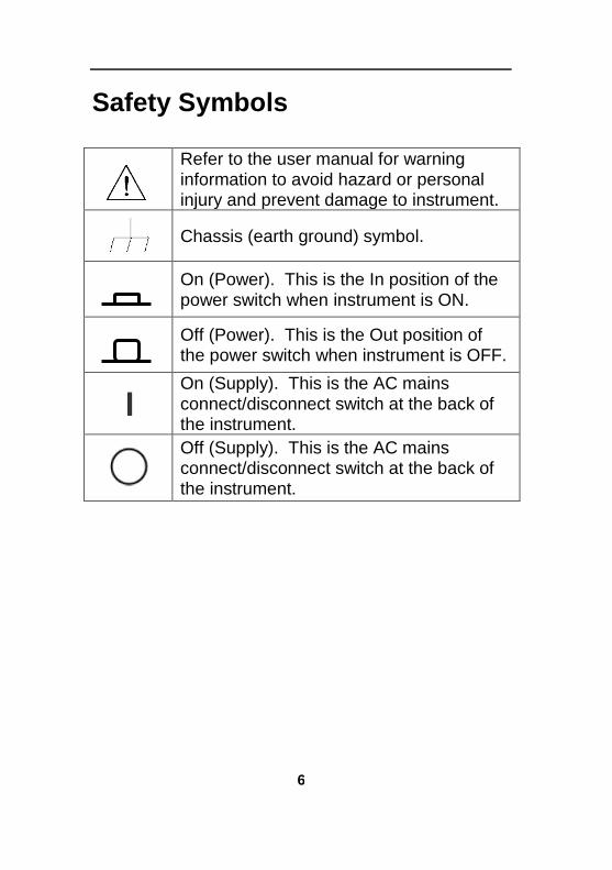
Safety Symbols
Refer to the user manual for warning information to avoid hazard or personal injury and prevent damage to instrument.
Chassis (earth ground) symbol.
On (Power). This is the In position of the power switch when instrument is ON.
Off (Power). This is the Out position of the power switch when instrument is OFF.
On (Supply). This is the AC mains connect/disconnect switch at the back of the instrument.
Off (Supply). This is the AC mains connect/disconnect switch at the back of the instrument.
7
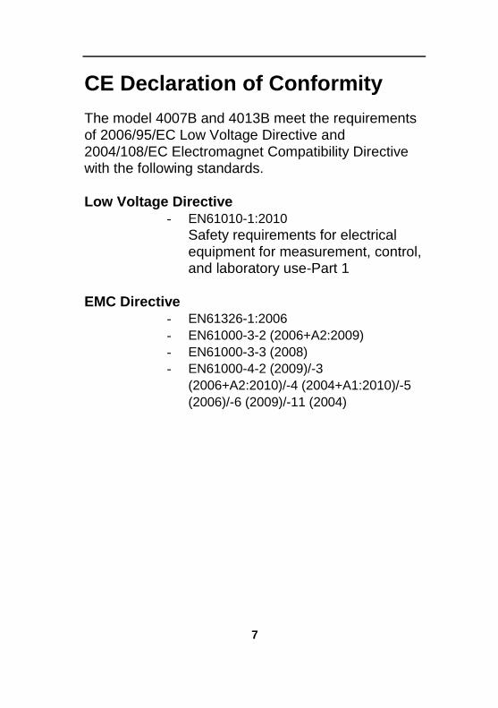
CE Declaration of Conformity The model 4007B and 4013B meet the requirements of 2006/95/EC Low Voltage Directive and 2004/108/EC Electromagnet Compatibility Directive with the following standards. Low Voltage Directive
- EN61010-1:2010
Safety requirements for electrical equipment for measurement, control, and laboratory use-Part 1
EMC Directive
- EN61326-1:2006
- EN61000-3-2 (2006+A2:2009)
- EN61000-3-3 (2008)
- EN61000-4-2 (2009)/-3
(2006+A2:2010)/-4 (2004+A1:2010)/-5
(2006)/-6 (2009)/-11 (2004)
8
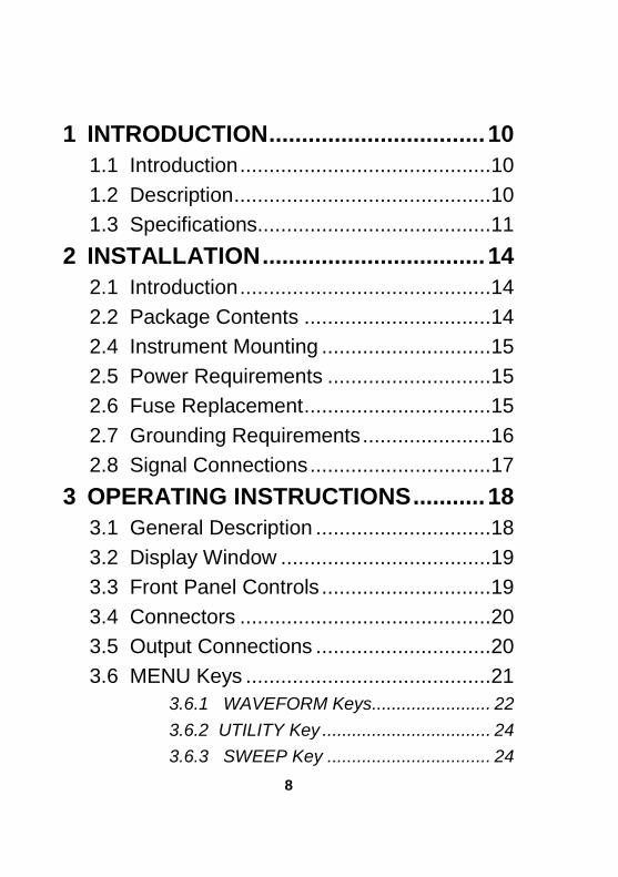
1 INTRODUCTION ................................. 10
1.1 Introduction ...........................................10
1.2 Description ............................................10
1.3 Specifications........................................11
2 INSTALLATION .................................. 14
2.1 Introduction ...........................................14
2.2 Package Contents ................................14
2.4 Instrument Mounting .............................15
2.5 Power Requirements ............................15
2.6 Fuse Replacement ................................15
2.7 Grounding Requirements ......................16
2.8 Signal Connections ...............................17
3 OPERATING INSTRUCTIONS ........... 18
3.1 General Description ..............................18
3.2 Display Window ....................................19
3.3 Front Panel Controls .............................19
3.4 Connectors ...........................................20
3.5 Output Connections ..............................20
3.6 MENU Keys ..........................................21
3.6.1 WAVEFORM Keys........................ 22
3.6.2 UTILITY Key .................................. 24
3.6.3 SWEEP Key ................................. 24

9 1
3.7 ON Key ................................................. 25
3.8 Cursor Keys .......................................... 26
3.9 Rotary Input Knob ................................. 26
3.10 Power-On Settings .............................. 26
3.11 Memory .............................................. 27
3.12 Displaying Errors ................................ 27
3.13 Quick Start .......................................... 28
3.13.1 Selecting a Standard Waveform . 28
3.13.2 Setting the Output ....................... 28
3.13.3 Using Voltage Offset .................. 28
3.13.4 Storing and Recalling a Waveform Generator Setup ....................................... 29
10
1 Introduction
1.1 Introduction
This manual contains information required to operate the B&K Precision model 4007B and 4013B DDS Function Generators. This section covers the instrument’s general description, specifications and characteristics.
1.2 Description
The 4007B and 4013B are versatile high performance function generators. Implemented using a DDS (direct digital synthesis) architecture, these instruments generate stable and precise sine, square, and triangle waveforms. Both models also provide linear and logarithmic sweep for users needing sweep capability. An auxiliary TTL output at the generator’s frequency is available to synchronize external devices. Up to 9 front panel settings can be saved to memory storage.
11 1
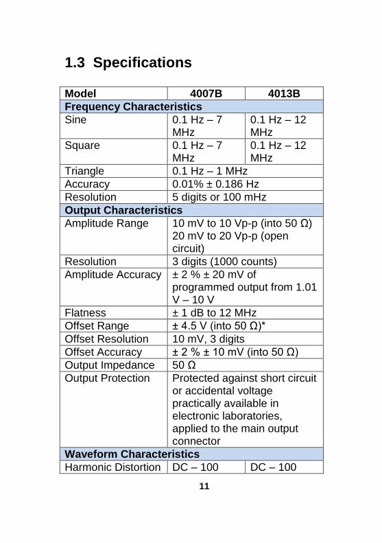
1.3 Specifications
Model 4007B 4013B
Frequency Characteristics
Sine 0.1 Hz – 7 MHz
0.1 Hz – 12 MHz
Square 0.1 Hz – 7 MHz
0.1 Hz – 12 MHz
Triangle 0.1 Hz – 1 MHz
Accuracy 0.01% ± 0.186 Hz
Resolution 5 digits or 100 mHz
Output Characteristics
Amplitude Range 10 mV to 10 Vp-p (into 50 Ω) 20 mV to 20 Vp-p (open circuit)
Resolution 3 digits (1000 counts)
Amplitude Accuracy ± 2 % ± 20 mV of programmed output from 1.01 V – 10 V
Flatness ± 1 dB to 12 MHz
Offset Range ± 4.5 V (into 50 Ω)*
Offset Resolution 10 mV, 3 digits
Offset Accuracy ± 2 % ± 10 mV (into 50 Ω)
Output Impedance 50 Ω
Output Protection Protected against short circuit or accidental voltage practically available in electronic laboratories, applied to the main output connector
Waveform Characteristics
Harmonic Distortion DC – 100 DC – 100

12
kHz, -55 dBc 100 kHz – 1 MHz, -45 dBc 1MHz – 7 MHz, -30 dBc
kHz, -55 dBc 100 kHz – 1 MHz, -45 dBc 1MHz – 12 MHz, -30 dBc
Square Rise/Fall Time
< 20 ns (10% to 90% at full amplitude into 50 Ω)
Variable Duty Cycle 20% to 80 %, up to 1 MHz for Square waveform
Symmetry Accuracy at 50%
< 1 %
Sweep Characteristics
Sweep Shape Linear or Logarithmic, up or down
Sweep Time 20 ms to 100 s
Input and Output
Sync Out TTL pulse at programmed frequency; 50 Ω source impedance
General
Memory Storage Store up to 9 instrument settings
Power Requirements
100 V – 240 V AC ± 10% (90 V – 264 VAC)
Max. Power Consumption
25 VA
Operating Temperature
0 °C – 50 °C
Storage Temperature
-10 °C – 70 °C
Humidity 95% RH, 0 °C – 30 °C
13 1
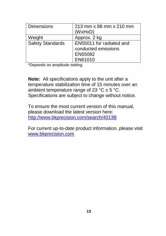
Dimensions 213 mm x 88 mm x 210 mm (WxHxD)
Weight Approx. 2 kg
Safety Standards EN55011 for radiated and conducted emissions EN55082 EN61010
*Depends on amplitude setting.
Note: All specifications apply to the unit after a temperature stabilization time of 15 minutes over an ambient temperature range of 23 °C ± 5 °C. Specifications are subject to change without notice. To ensure the most current version of this manual, please download the latest version here: http://www.bkprecision.com/search/4013B For current up-to-date product information, please visit www.bkprecision.com
14
2 Installation
2.1 Introduction
This section contains installation information, power requirements, initial inspection and signal connections for the 4007B and 4013B signal generators.
2.2 Package Contents
Please inspect the instrument mechanically and electrically upon receiving it. Unpack all items from the shipping carton, and check for any obvious signs of physical damage that may have occurred during transportation. Report any damage to the shipping agent immediately. Save the original packing carton for possible future reshipment. Every generator is shipped with the following contents:
4007B / 4013B DDS function generator
AC Power Cord
Certificate of Calibration
Verify that all items above are included in the shipping container. If anything is missing, please contact B&K Precision.
15 1
2.4 Instrument Mounting
The 4007B and 4013B Function Generators are intended for bench use. The instrument includes a front feet tilt mechanism for optimum panel viewing angle. The instrument does not require special cooling when operated within conventional temperature limits. It may be installed in a closed rack or test station if proper air flow can assure removing about 15 W of power dissipation.
2.5 Power Requirements
The 4007B and 4013B can be operated from any source of 90V to 264V AC, frequency from 48Hz to 66Hz. The maximum power consumption is 25 VA. Use a slow blow fuse of 1A, UL/CSA approved as indicated on the rear panel of the instrument. The instrument power fuse is located in the AC input plug. To access the fuse, first disconnect the power cord and then remove the fuse cartridge.
2.6 Fuse Replacement
There is a 1A, 250V rated slow blow fuse at the AC input. Should the fuse ever get blown, follow the steps below to replace:
16
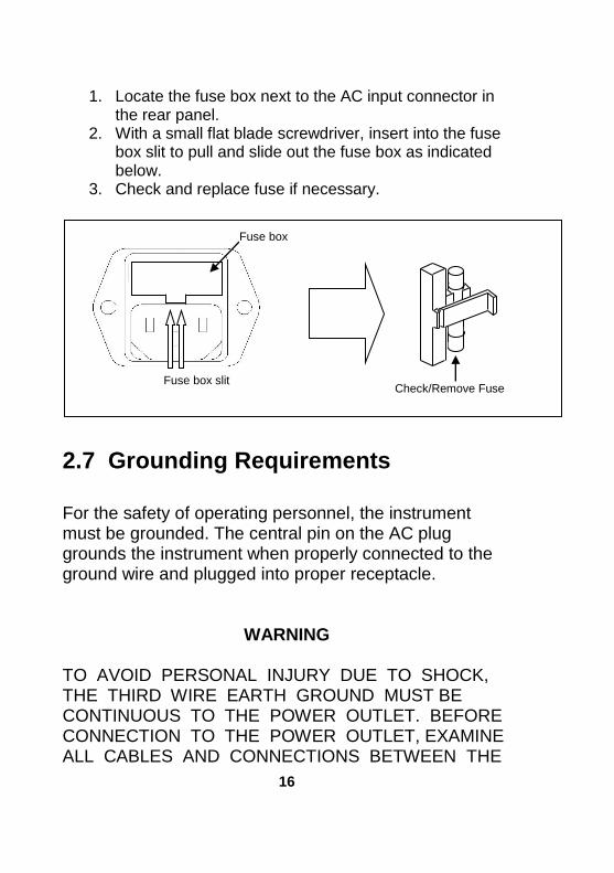
1. Locate the fuse box next to the AC input connector in the rear panel.
2. With a small flat blade screwdriver, insert into the fuse box slit to pull and slide out the fuse box as indicated below.
3. Check and replace fuse if necessary.
2.7 Grounding Requirements
For the safety of operating personnel, the instrument must be grounded. The central pin on the AC plug grounds the instrument when properly connected to the ground wire and plugged into proper receptacle.
WARNING TO AVOID PERSONAL INJURY DUE TO SHOCK, THE THIRD WIRE EARTH GROUND MUST BE CONTINUOUS TO THE POWER OUTLET. BEFORE CONNECTION TO THE POWER OUTLET, EXAMINE ALL CABLES AND CONNECTIONS BETWEEN THE
Fuse box slit
Fuse box
Check/Remove Fuse

17 1
UNIT AND THE FACILITY POWER FOR A CONTINUOUS EARTH GROUND PATH. THE POWER CABLE MUST MEET IEC SAFETY STANDARDS.
2.8 Signal Connections
Use RG58U 50Ω or equivalent coaxial cables for all input and output signals to and from the instrument.
18
3 Operating Instructions
3.1 General Description
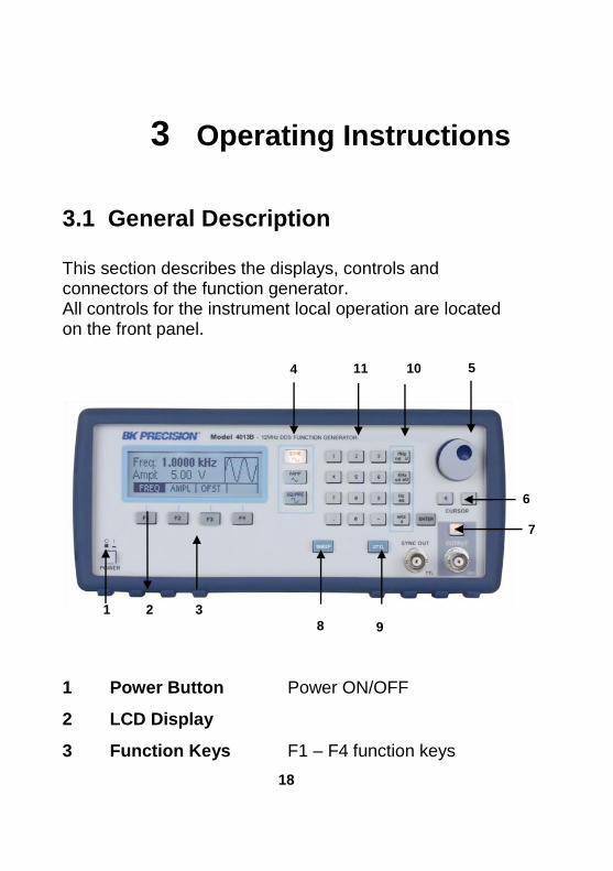
This section describes the displays, controls and connectors of the function generator. All controls for the instrument local operation are located on the front panel.
1 Power Button Power ON/OFF
2 LCD Display
3 Function Keys F1 – F4 function keys
1 2 3
4 11 10 5
6
7
9 8
19 1
4 Waveform Buttons Select Sine, Ramp/Triangle, Square waveform shape
5 Rotary Knob
6 Cursor Keys
7 Output ON/OFF Enable/Disable Output
8 SWEEP Button Selects Sweep function menu
9 UTIL Button Utility menu
10 Units Keys
11 Numeric Keypad
3.2 Display Window
The function generator has a graphic LCD display that can display up to 124 x 32 dots. When you power-on the unit sine waveform is selected and current settings appear in the display. The bottom displays a menu (selectable with function keys) that corresponds to the function, parameter or mode display selected.
3.3 Front Panel Controls
The front-panel controls select, display, and change parameter, function, and mode settings.
Use the numerical keypad, rotary input knob and the cursor
movement keys to enter data into the waveform generator.
To change a setting:
20
1. Press the key that leads to the item to change. 2. Move cursor using cursor keys to the appropriate position in the numeric field (if applicable). 3. Use the rotary input or the numerical keyboard to change the value of the displayed item. Changes take effect immediately.
3.4 Connectors
The function generator has two BNC connectors on the front
panel where you can connect coaxial cables. These coaxial
cables serve as carrier lines for output signals delivered from
the function generator.
Output
Use this connector to transfer the main output signal from the
function generator.
Sync Out
Use this connector to output a positive TTL sync pulse
generated at each waveform cycle.
3.5 Output Connections
The waveform generator output circuits operate as a 50 Ω voltage source working into a 50 Ω load. At higher frequencies, non terminated or improperly terminated output causes aberrations on the output waveform. In addition, loads less than 50 Ω reduce the waveform amplitude, while loads more than 50 Ω increase waveform amplitude. Excessive distortion or aberrations caused by improper termination are less noticeable at lower frequencies,
21 1
especially with sine and triangle waveforms. To ensure waveform integrity, follow these precautions: 1. Use good quality 50 Ω coaxial cable and connectors. 2. Make all connections tight and as short as possible. 3. Use good quality attenuators if it is necessary to reduce waveform amplitudes applied to sensitive circuits. 4. Use termination or impedance-matching devices to avoid reflections. 5. Ensure that attenuators and terminations have adequate power handling capabilities. If there is a DC voltage across the output load, use a coupling capacitor in series with the load. The time constant of the coupling capacitor and load must be long enough to maintain pulse flatness. Impedance Matching If the waveform generator is driving a high impedance, such as a 1 MΩ input impedance (paralleled by a stated capacitance) of an oscilloscope vertical input, connect the transmission line to a 50 Ω attenuator, a 50 Ω termination and to the oscilloscope input. The attenuator isolates the input capacitance of the device and terminates the waveform generator properly.
3.6 MENU Keys
These keys select the main menus for displaying or changing a parameter, function or mode.
22
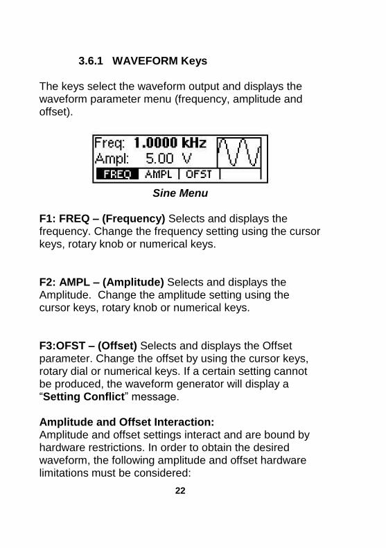
3.6.1 WAVEFORM Keys The keys select the waveform output and displays the waveform parameter menu (frequency, amplitude and offset).
Sine Menu
F1: FREQ – (Frequency) Selects and displays the frequency. Change the frequency setting using the cursor keys, rotary knob or numerical keys. F2: AMPL – (Amplitude) Selects and displays the Amplitude. Change the amplitude setting using the cursor keys, rotary knob or numerical keys. F3:OFST – (Offset) Selects and displays the Offset parameter. Change the offset by using the cursor keys, rotary dial or numerical keys. If a certain setting cannot be produced, the waveform generator will display a “Setting Conflict” message. Amplitude and Offset Interaction: Amplitude and offset settings interact and are bound by hardware restrictions. In order to obtain the desired waveform, the following amplitude and offset hardware limitations must be considered:
23 1
The offset voltage has three ranges as follows:
Output Voltage Range
Constraints of Amplitude + Offset
1.01 volt to 10.00 volts
(Vp-p)/2 + |offset| <= 5 volts
0.101 volt to 1 volt
(Vp-p)/2 + |offset| <= 0.5 volts
0.010 volt to 0.100 volt
(Vp-p)/2 + |offset| <= 0.05 volts
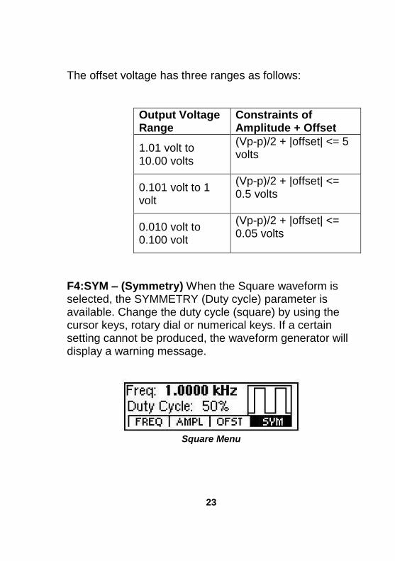
F4:SYM – (Symmetry) When the Square waveform is selected, the SYMMETRY (Duty cycle) parameter is available. Change the duty cycle (square) by using the cursor keys, rotary dial or numerical keys. If a certain setting cannot be produced, the waveform generator will display a warning message.
Square Menu
24
3.6.2 UTILITY Key
Utility Menu
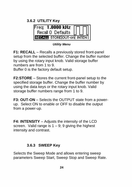
F1: RECALL – Recalls a previously stored front-panel setup from the selected buffer. Change the buffer number by using the rotary input knob. Valid storage buffer numbers are from 1 to 9. Buffer 0 is the factory default setup.
F2:STORE – Stores the current front-panel setup to the specified storage buffer. Change the buffer number by using the data keys or the rotary input knob. Valid storage buffer numbers range from 1 to 9. F3: OUT-ON – Selects the OUTPUT state from a power-up. Select ON to enable or OFF to disable the output from a power-up. F4: INTENSITY – Adjusts the intensity of the LCD screen. Valid range is 1 – 9; 9 giving the highest intensity and contrast.
3.6.3 SWEEP Key
Selects the Sweep Mode and allows entering sweep parameters Sweep Start, Sweep Stop and Sweep Rate.
25 1
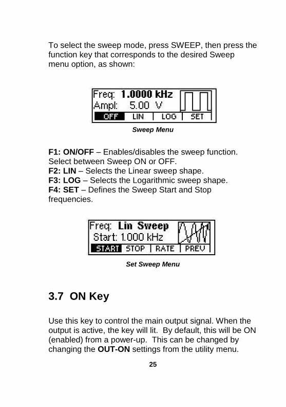
To select the sweep mode, press SWEEP, then press the function key that corresponds to the desired Sweep menu option, as shown:
Sweep Menu
F1: ON/OFF – Enables/disables the sweep function. Select between Sweep ON or OFF. F2: LIN – Selects the Linear sweep shape. F3: LOG – Selects the Logarithmic sweep shape. F4: SET – Defines the Sweep Start and Stop frequencies.
Set Sweep Menu
3.7 ON Key
Use this key to control the main output signal. When the output is active, the key will lit. By default, this will be ON (enabled) from a power-up. This can be changed by changing the OUT-ON settings from the utility menu.
26
3.8 Cursor Keys
Use these keys to move the cursor (when visible) either left or right. They are used in conjunction with the rotary input knob to set the step size of the rotary input knob.
3.9 Rotary Input Knob
Use this knob to increase and decrease numeric values. The cursor indicates the low-order position of the displayed value which changes when you rotate the knob (for straight numeric entries only). For other types of data, the whole value changes when you rotate the knob.
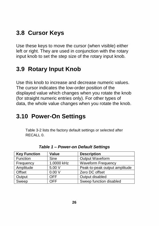
3.10 Power-On Settings
Table 3-2 lists the factory default settings or selected after
RECALL 0.
Table 1 – Power-on Default Settings
Key Function Value Description
Function Sine Output Waveform
Frequency 1.0000 kHz Waveform Frequency
Amplitude 5.00 V Peak-to-peak output amplitude
Offset 0.00 V Zero DC offset
Output OFF Output disabled
Sweep OFF Sweep function disabled
27 1
3.11 Memory
The waveform generator uses non-volatile flash memory for storing the front panel settings. Up to 9 front panel settings can be stored (not including default settings).
3.12 Displaying Errors
The waveform generator displays error messages when front-panel settings are either invalid or may produce unexpected results.
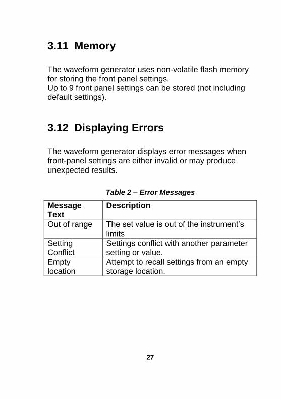
Table 2 – Error Messages
Message Text
Description
Out of range The set value is out of the instrument’s limits
Setting Conflict
Settings conflict with another parameter setting or value.
Empty location
Attempt to recall settings from an empty storage location.
28
3.13 Quick Start
This section explains how to generate various waveforms and modify the output waveform. * Generating a waveform output * Modifying waveform output * Storing and recalling a waveform generator setup
3.13.1 Selecting a Standard Waveform
You can select several standard waveforms as: sine, triangle, square. Creating a standard waveform requires selecting the waveform type, parameters and their settings that define the waveform. Generating a standard waveform requires the following: * Selecting the waveform * Setting the output frequency * Setting the output amplitude and offset
3.13.2 Setting the Output
To set the output channel, press the Output ON key. The key will lit indicating the output is enabled.
3.13.3 Using Voltage Offset Through the offset parameter you can add a positive or negative DC level to the output waveform.
29 1
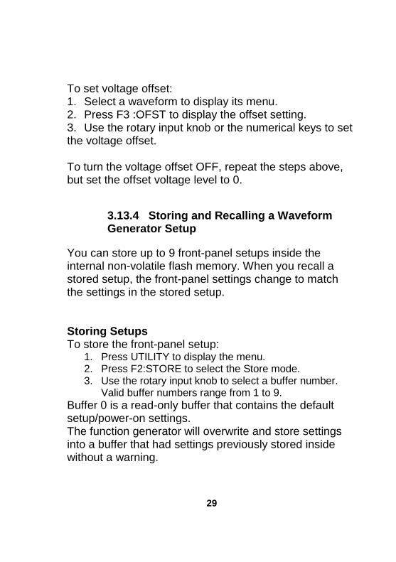
To set voltage offset: 1. Select a waveform to display its menu. 2. Press F3 :OFST to display the offset setting. 3. Use the rotary input knob or the numerical keys to set the voltage offset. To turn the voltage offset OFF, repeat the steps above, but set the offset voltage level to 0.
3.13.4 Storing and Recalling a Waveform Generator Setup
You can store up to 9 front-panel setups inside the internal non-volatile flash memory. When you recall a stored setup, the front-panel settings change to match the settings in the stored setup. Storing Setups To store the front-panel setup:
1. Press UTILITY to display the menu. 2. Press F2:STORE to select the Store mode. 3. Use the rotary input knob to select a buffer number.
Valid buffer numbers range from 1 to 9.
Buffer 0 is a read-only buffer that contains the default setup/power-on settings. The function generator will overwrite and store settings into a buffer that had settings previously stored inside without a warning.
30
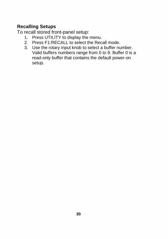
Recalling Setups To recall stored front-panel setup:
1. Press UTILITY to display the menu. 2. Press F1:RECALL to select the Recall mode. 3. Use the rotary input knob to select a buffer number.
Valid buffers numbers range from 0 to 9. Buffer 0 is a read-only buffer that contains the default power-on setup.

SERVICE INFORMATION
Warranty Service: Please go the support and service section on our website
www.bkprecision.com to obtain a RMA #. Return the product in the original
packaging with proof of purchase to the address below. Clearly state on the RMA the
performance problem and return any leads, probes, connectors and accessories that
you are using with the device.
Non-Warranty Service: Please go the support and service section on our website
www.bkprecision.com to obtain a RMA #. Return the product in the original
packaging to the address below. Clearly state on the RMA the performance problem
and return any leads, probes, connectors and accessories that you are using with the
device. Customers not on an open account must include payment in the form of a
money order or credit card. For the most current repair charges please refer to the
service and support section on our website.
Return all merchandise to B&K Precision Corp. with pre-paid shipping. The flat-rate repair charge for Non-Warranty Service does not include return shipping. Return shipping to locations in North America is included for Warranty Service. For overnight shipments and non-North American shipping fees please contact B&K Precision Corp.
B&K Precision Corp. 22820 Savi Ranch Parkway
Yorba Linda, CA 92887 www.bkprecision.com
714-921-9095 Include with the returned instrument your complete return shipping address, contact name, phone number and description of problem.

32
LIMITED THREE-YEAR WARRANTY B&K Precision Corp. warrants to the original purchaser that its products and the component parts thereof, will be free from defects in workmanship and materials for a period of three years from date of purchase.
B&K Precision Corp. will, without charge, repair or replace, at its option, defective product or component parts. Returned product must be accompanied by proof of the purchase date in the form of a sales receipt. To help us better serve you, please complete the warranty registration for your new instrument via our website www.bkprecision.com Exclusions: This warranty does not apply in the event of misuse or abuse of the product or as a result of unauthorized alterations or repairs. The warranty is void if the serial number is altered, defaced or removed.
B&K Precision Corp. shall not be liable for any consequential damages, including without limitation damages resulting from loss of use. Some states do not allow limitations of incidental or consequential damages. So the above limitation or exclusion may not apply to you. This warranty gives you specific rights and you may have other rights, which vary from state-to-state.
B&K Precision Corp. 22820 Savi Ranch Parkway
Yorba Linda, CA 92887 www.bkprecision.com
714-921-9095
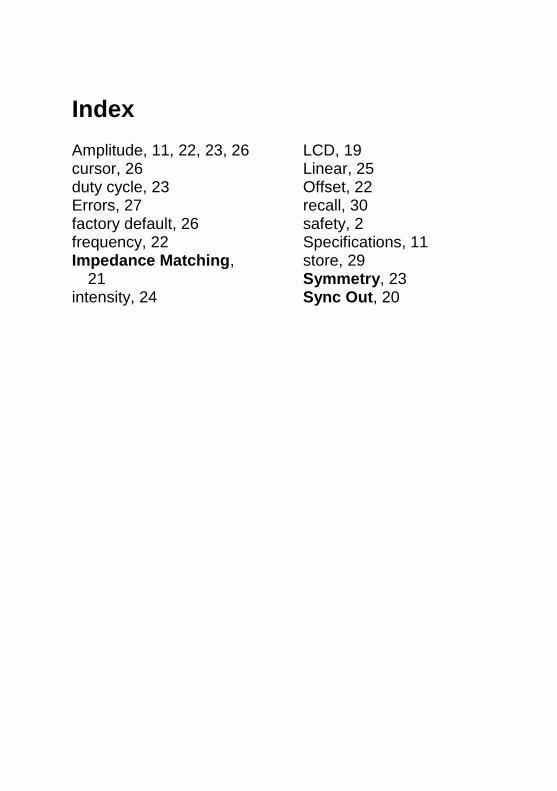
Index Amplitude, 11, 22, 23, 26 cursor, 26 duty cycle, 23 Errors, 27 factory default, 26 frequency, 22 Impedance Matching,
21 intensity, 24
LCD, 19 Linear, 25 Offset, 22 recall, 30 safety, 2 Specifications, 11 store, 29 Symmetry, 23 Sync Out, 20

34

35

22820 Savi Ranch Parkway Yorba Linda, CA 92887 www.bkprecision.com
© 2012 B&K Precision Corp.
v042913