4002 ieee transactions on microwave …mingyu/publications/p201312.pdf4002 ieee transactions on...
TRANSCRIPT
4002 IEEE TRANSACTIONS ON MICROWAVE THEORY AND TECHNIQUES, VOL. 60, NO. 12, DECEMBER 2012
A -Band Fully Tunable Cavity FilterBahram Yassini, Member, IEEE, Ming Yu, Fellow, IEEE, and Brian Keats
Abstract—A TE -band tunable filter with a stable andcontinuous tuning performance is presented in this paper. Bothbandwidth and center-frequency tunability are demonstrated bycascading six-pole pseudo-low-pass and pseudo-high-pass tunablefilters. A novel mode-splitter resonator and coupling configura-tion enabling cross-coupled planar TE filter realization is in-troduced in this paper. The concept can be applied to back-to-back coupled TE resonators as well. The filter design is verifiedthrough fabrication of multiple tunable filters that demonstrates500 MHz of tuning range with a stable RF tuning performance.
Index Terms—Cavity resonators, coupling, reconfigurable archi-tectures, TE , tunable filters.
I. INTRODUCTION
R EALIZING a flexible transceiver, particularly for recon-figurable payloads, presents a number of technical chal-
lenges; bandwidth tunability, center-frequency tunability, andselectivity must be achieved over a wide frequency range [1]. Iftunability is realized by resizing cavities, the actuation systemmust exhibit minimal power consumption. Latching is requiredto ensure that power is only consumed during a tuning operationand to maintain filter performance while the mechanism is un-powered. A key design parameter in realizing the filter functionfor a tunable filter is the desired mode.The field pattern of a cylindrical cavity operating in the TE
mode is an attractive choice for tunable filters. Along with ahigh quality factor, the field pattern and current distributionoffer key advantages for realizing tunable filters. However, thismode of operation is degenerate with a pair of low-quality-factor TM modes that need to be separated from the oper-ating TE modewithout degrading the quality factor or overallfilter performance [2], [3]. Realization of a filter function in across-coupled resonator configuration such as this presents an-other challenge [4]; however, a cross-coupled realization is es-sential since a planar layout allows for a single actuation mech-anism to realize tunability. To the best of our knowledge, nodemonstration of stable tuning performance using this mode canbe found in the literature.The most efficient technique to split the degenerate TM
mode from the operating TE mode is shaping the cavity res-onator [2], [3]. This technique uses a barrel-shaped cavity re-
Manuscript received July 10, 2012; revised September 19, 2012; acceptedSeptember 24, 2012. Date of publication November 15, 2012; date of currentversion December 13, 2012. This work was supported by the Canadian SpaceAgency (CSA). This paper is an expanded paper from the IEEE MTT-S Inter-national Microwave Symposium, Montreal, QC, Canada, June 17-22, 2012.The authors are with COM DEV Ltd., Cambridge, ON, Canada
N1R 7H6 (e-mail: [email protected]; [email protected];[email protected]).Color versions of one or more of the figures in this paper are available online
at http://ieeexplore.ieee.org.Digital Object Identifier 10.1109/TMTT.2012.2224367
lating the modes of a cylindrical cavity to those of a sphericalcavity. However, this shaping method increases the overall filterfootprint and is difficult to manufacture. Another technique in-troduced in [4] employs metallic posts to split the degenerateTM mode, but it suffers from fabrication complexity andperformance degradation. In [5], a disc-loaded technique is pre-sented for the -band. The efficacy of this technique is not sub-stantiated and clarified. In [5], however, the disc is not used tosplit the degenerate TM mode.All of the published TE filters use a below-resonance iris
(short iris) to couple two cavities. This type of iris only realizesone coupling sign in a side-to-side (planar) cross-coupled cavityconfiguration. Therefore, it does not offer an all-purpose andcomprehensive solution to realize any desired filter function in aplanar and cross-coupled fashion using TE cavity resonator.Although the extracted-pole technique [6] can be employed
to realize a filter response in a planar fashion using the samesign coupling configuration, this technique suffers from a sizedisadvantage. The extracted pole design is not attractive for tun-able filter design because of the frequency-sensitive transmis-sion lines used between cavities.The back-to-back coupling employing an offset-cavity tech-
nique in two layers described in [4] can provide both positiveand negative couplings. This method increases the overall filterenvelope due to the offset cavity configuration. This configu-ration is not practical where a single actuation mechanism willsimultaneously tune all cavities.The single-layer cross-coupled cavity design presented in this
paper is an attractive filter configuration, particularly for tunablefilter realization. This configuration requires both positive andnegative coupling to realize the desired filter function. A designthat can address both coupling signs in a planar cross-coupledfashion has not been introduced in the literature. The presentedtunable filter technology offers both bandwidth and center-fre-quency tunability. By matching the tuning curves of the cav-ities, a single actuation mechanism can be used for all filtercavities. This configuration minimizes power consumption andcomplexity.
II. END-CAP METAL-RING TM MODE-SPLITTER
In order to split the degenerate TM mode, a feature is re-quired that will move the TM resonance, while minimallyaffecting the desired TE011 mode.Electromagnetic field and current distribution for the desired
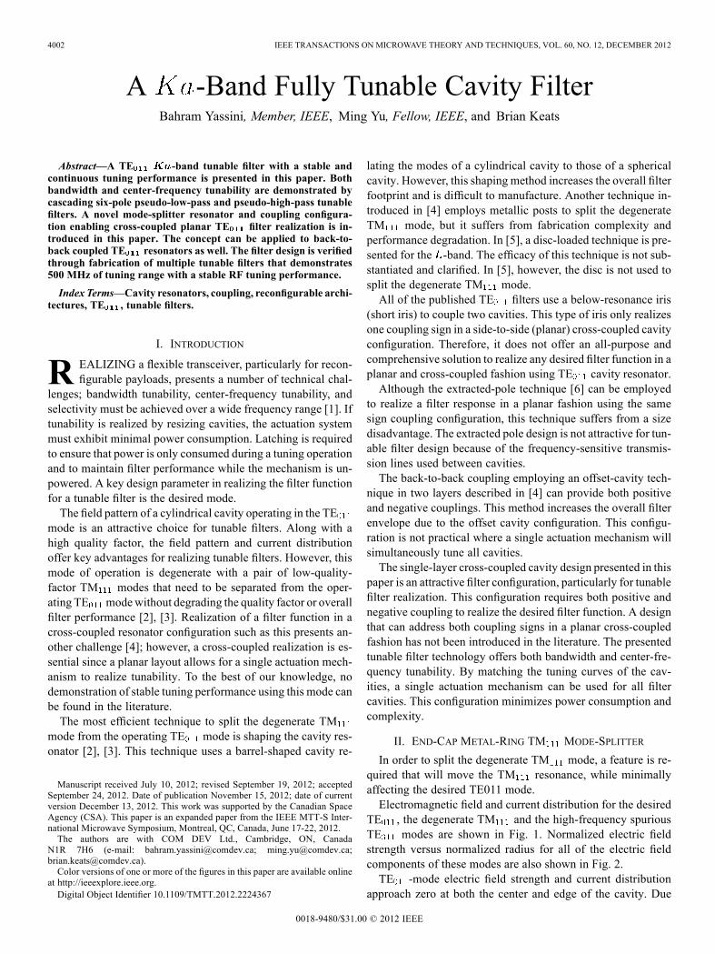
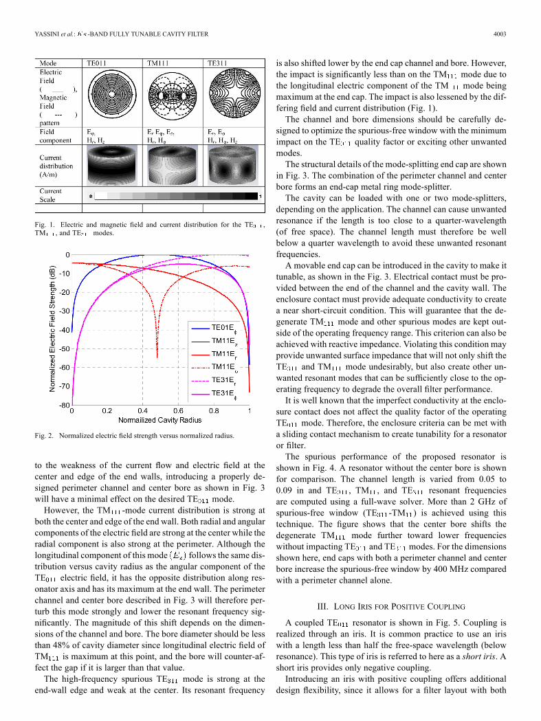
TE , the degenerate TM and the high-frequency spuriousTE modes are shown in Fig. 1. Normalized electric fieldstrength versus normalized radius for all of the electric fieldcomponents of these modes are also shown in Fig. 2.TE -mode electric field strength and current distribution
approach zero at both the center and edge of the cavity. Due
0018-9480/$31.00 © 2012 IEEE
YASSINI et al.: -BAND FULLY TUNABLE CAVITY FILTER 4003
Fig. 1. Electric and magnetic field and current distribution for the TE ,TM , and TE modes.
Fig. 2. Normalized electric field strength versus normalized radius.
to the weakness of the current flow and electric field at thecenter and edge of the end walls, introducing a properly de-signed perimeter channel and center bore as shown in Fig. 3will have a minimal effect on the desired TE mode.However, the TM -mode current distribution is strong at
both the center and edge of the end wall. Both radial and angularcomponents of the electric field are strong at the center while theradial component is also strong at the perimeter. Although thelongitudinal component of this mode follows the same dis-tribution versus cavity radius as the angular component of theTE electric field, it has the opposite distribution along res-onator axis and has its maximum at the end wall. The perimeterchannel and center bore described in Fig. 3 will therefore per-turb this mode strongly and lower the resonant frequency sig-nificantly. The magnitude of this shift depends on the dimen-sions of the channel and bore. The bore diameter should be lessthan 48% of cavity diameter since longitudinal electric field ofTM is maximum at this point, and the bore will counter-af-fect the gap if it is larger than that value.The high-frequency spurious TE mode is strong at the
end-wall edge and weak at the center. Its resonant frequency
is also shifted lower by the end cap channel and bore. However,the impact is significantly less than on the TM mode due tothe longitudinal electric component of the TM mode beingmaximum at the end cap. The impact is also lessened by the dif-fering field and current distribution (Fig. 1).The channel and bore dimensions should be carefully de-
signed to optimize the spurious-free window with the minimumimpact on the TE quality factor or exciting other unwantedmodes.The structural details of the mode-splitting end cap are shown
in Fig. 3. The combination of the perimeter channel and centerbore forms an end-cap metal ring mode-splitter.The cavity can be loaded with one or two mode-splitters,
depending on the application. The channel can cause unwantedresonance if the length is too close to a quarter-wavelength(of free space). The channel length must therefore be wellbelow a quarter wavelength to avoid these unwanted resonantfrequencies.A movable end cap can be introduced in the cavity to make it
tunable, as shown in the Fig. 3. Electrical contact must be pro-vided between the end of the channel and the cavity wall. Theenclosure contact must provide adequate conductivity to createa near short-circuit condition. This will guarantee that the de-generate TM mode and other spurious modes are kept out-side of the operating frequency range. This criterion can also beachieved with reactive impedance. Violating this condition mayprovide unwanted surface impedance that will not only shift theTE and TM mode undesirably, but also create other un-wanted resonant modes that can be sufficiently close to the op-erating frequency to degrade the overall filter performance.It is well known that the imperfect conductivity at the enclo-
sure contact does not affect the quality factor of the operatingTE mode. Therefore, the enclosure criteria can be met witha sliding contact mechanism to create tunability for a resonatoror filter.The spurious performance of the proposed resonator is
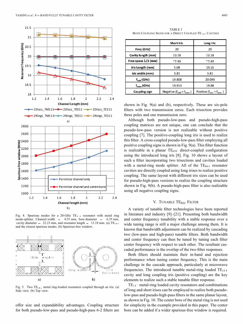
shown in Fig. 4. A resonator without the center bore is shownfor comparison. The channel length is varied from 0.05 to0.09 in and TE , TM , and TE resonant frequenciesare computed using a full-wave solver. More than 2 GHz ofspurious-free window (TE -TM ) is achieved using thistechnique. The figure shows that the center bore shifts thedegenerate TM mode further toward lower frequencieswithout impacting TE and TE modes. For the dimensionsshown here, end caps with both a perimeter channel and centerbore increase the spurious-free window by 400 MHz comparedwith a perimeter channel alone.
III. LONG IRIS FOR POSITIVE COUPLING
A coupled TE resonator is shown in Fig. 5. Coupling isrealized through an iris. It is common practice to use an iriswith a length less than half the free-space wavelength (belowresonance). This type of iris is referred to here as a short iris. Ashort iris provides only negative coupling.Introducing an iris with positive coupling offers additional
design flexibility, since it allows for a filter layout with both

4004 IEEE TRANSACTIONS ON MICROWAVE THEORY AND TECHNIQUES, VOL. 60, NO. 12, DECEMBER 2012
Fig. 3. Tunable TE resonator with mode-splitter rings.
coupling signs. An iris with a length longer than half of thefree-space wavelength (over the resonance) can provide positivecoupling (opposite sign of the short iris) between cavities. Thisconfiguration is referred to here as a long iris. The following isan example on how these two irises are different.Table I shows the simulated odd- and even-mode frequen-
cies for short and long irises in a side-to-side metal ring loadedTE coupled resonators. It has to be noted that cavities shouldbe properly sized to fit the long iris without performance degra-dation. It is clear from this table that the coupling sign of the longiris is opposite of the one for the short iris. The idea of the longiris is also applicable to the back-to-back coupled resonator.One interesting characteristic of the long iris is its low sen-
sitivity to its height variation and to the cavity length (cavityresonant frequency) change. This feature makes it a good can-didate for applications that require stable coupling over a widefrequency range or cavity-length variation. Consider a block oftwo coupled side-by-side TE tunable resonator, as shown inFig. 5. The top end walls of both cavities include metal ringsdisplaced by 0.02 in to represent more than 450-MHz range at-band (20 GHz). Coupling variation for short and long irises
is shown in Fig. 6. This figure shows that the long iris couplingvalue variation is less than 3.5% versus 10% for the short irisover more than 450 MHz (around 2.5%) of tuning range. There-fore, tunable filters with a stable response can be designed byincorporating long irises in the design.
IV. APPLICATION IN FILTER DESIGN
The introduction of a long iris offering positive coupling(along with a short iris with negative coupling) can be em-ployed to improve the TE011 filter design for both functionalityand layout. Realizing many filter functions in a cross-coupledplanar TE011 structure is feasible by employing long and shortirises properly.
A. A Four-Pole Elliptic Filter Function
Both coupling signs are required to realize a cross-coupledfour-pole elliptical filter function with two transmission zeros.Long and short irises can be used to realize such a filter in aplanar TE configuration, as shown in Fig. 7. The filter struc-ture comprises of three sequentially coupled long irises (posi-tive signs) and one short iris to realize negative cross coupling.Resonators are loaded metal-ring mode splitters to isolate theTM mode. Input and output ports are rotated by 30 to min-imize stray coupling and balance the notches. Full-wave simu-lation of such a filter is shown in Fig. 8. The in-band responseis clean, and the degenerate mode is shifted down as expected.Simulation demonstrates that the degenerate TM mode islowered by another 450 MHz by the center bore as expected.
B. Realizing Planar Asymmetric Filter Functions
Asymmetric filter functions can be realized using trisectionbuilding blocks as shown in Fig. 9. Trisection building blocks
YASSINI et al.: -BAND FULLY TUNABLE CAVITY FILTER 4005
Fig. 4. Spurious modes for a 20-GHz TE resonator with metal ringmode-splitter. Channel width 0.51 mm, bore diameter 6.35 mm,cavity diameter 22.23 mm, and resonator length 13.18 mm. (a) TEand the closest spurious modes. (b) Spurious-free window.
Fig. 5. Two TE metal ring-loaded resonators coupled through an iris. (a)Side view. (b) Top view.
offer size and expandability advantages. Coupling structurefor both pseudo-low-pass and pseudo-high-pass 6-2 filters are
TABLE IBOTH COUPLING SIGNS FOR A DIRECT COUPLED TE CAVITIES
shown in Fig. 9(a) and (b), respectively. These are six-polefilters with two transmission zeros. Each trisection providesthree poles and one transmission zero.Although both pseudo-low-pass and pseudo-high-pass
coupling matrices are not unique, one can conclude that thepseudo-low-pass version is not realizable without positivecoupling [7]. The positive-coupling long iris is used to realizethis filter. A cross-coupled pseudo-low-pass filter employing allpositive coupling signs is shown in Fig. 9(a). This filter functionis realizable in a planar TE direct-coupled configurationusing the introduced long iris [8]. Fig. 10 shows a layout ofsuch a filter incorporating two trisections and cavities loadedwith a metal-ring mode splitter. All of the TE resonatorcavities are directly coupled using long irises to realize positivecoupling. The same layout with different iris sizes can be usedfor pseudo-high-pass versions to realize the coupling structureshown in Fig. 9(b). A pseudo-high-pass filter is also realizableusing all negative coupling signs.
V. TUNABLE TE FILTER
A variety of tunable filter technologies have been reportedin literature and industry [9]–[21]. Presenting both bandwidthand center frequency tunability with a stable response over awide tuning range is still a major challenge among them. It isknown that bandwidth adjustment can be realized by cascadingtwo (low-pass and high-pass) tunable filters. Both bandwidthand center frequency can then be tuned by tuning each filtercenter frequency with respect to each other. The resultant cas-caded performance is the overlap of the two filter responses.Both filters should maintain their in-band and rejection
performance when tuning center frequency. This is the mainchallenge in the cascade approach, particularly at microwavefrequencies. The introduced tunable metal-ring loaded TEcavity and long coupling iris (positive coupling) are the keyelements to realize such a stable tunable filter response.TE metal-ring loaded cavity resonators and combinations
of long and short irises can be employed to realize both pseudo-low-pass and pseudo-high-pass filters in the same planar layout,as shown in Fig. 10. The center bore of the metal ring is not usedfor simplicity in the example provided in this paper. The centerbore can be added if a wider spurious-free window is required.

4006 IEEE TRANSACTIONS ON MICROWAVE THEORY AND TECHNIQUES, VOL. 60, NO. 12, DECEMBER 2012
Fig. 6. Coupling value variation for a -band (20 GHz) metal ring-loadedTE coupled resonators. (a) Coupling variation versus displacement (b) Cou-pling variation versus resonance frequency.
It is important where possible to use (long) positive cou-pling irises in both designs to achieve a stable RF performanceover the tuning range as the long iris exhibits a very small cou-pling variation over the tuning range (Fig. 6). Therefore, thepseudo-low-pass filter is realized using all positive (long) cou-pling irises. The pseudo-high-pass version is realized using fivepositive (long) coupling irises for sequential coupling and twonegative (short) coupling irises for cross coupling. Input andoutput irises are located at 90 with respect to the sequential
Fig. 7. Four-pole planar TE filter incorporating mode-spliter ring and longand short irises to realize elliptic filter function.
coupling irises (Iris-12 and Iris-56, respectively) to suppressTE coupling and reduce stray coupling.Each cavity has a different resonant frequency, as shown by
coupling matrices in Fig. 9(a) and (b). Therefore, tuning curvesof cavities must match each other to maintain filter responseover the tuning range. Independent cavity actuation can achievethat at the cost of multiple actuation systems and a more com-plex tuning mechanism. A single actuation mechanism is pos-sible if the tuning curves are matched for each cavity.The resonant frequency of each TE cavity is governed by
the following equation:
(1)
where is the first zero of the derivative of the Bessel functionof the first kind and order 0 and and are length and radiusof the th cavity, respectively.The derivative of resonant frequency of each cavity with re-
spect to its length can be derived from (1) as
(2)
Therefore, the following criterion ensures that resonatortuning curves matches at the middle of the tuning range:
(3)
Considering the typical dimensions of a -band (20 GHz)TE filter (Fig. 4) and (2), the tuning slope is in the range of

YASSINI et al.: -BAND FULLY TUNABLE CAVITY FILTER 4007
Fig. 8. Simulated response of a four-pole planar TE elliptic filter. The de-sign with (blue) and without (red) center bore shows that the center bore helpsto further split the TM mode by 450 MHz without affecting TE spurious.(a) Transmission response. (b) Return loss.
Fig. 9. Coupling matrix for (a) pseudo-low-pass and (b) pseudo-high-pass six-pole filter.
Fig. 10. Cross-coupled planar TE filter layout incorporating metal-ringmode-splitter and long/short irises to realize both pseudo-low-pass andpseudo-high-pass 6-2 filter functions.
Fig. 11. Tunable filter moving section including tuning plate, tuningdisc/plunger, and sliding contact.
10 MHz/mil. Thus, 25 mil ( of cavity length) is requiredfor 250-MHz (a total of 500 MHz) tuning range. Bearing inmind the self-coupling values presented in the coupling struc-ture from Fig. 9, a bandwidth of 170MHz, and a tuning range of500 MHz, one can use the first-order approximation of (3) andderive the following formula for the length of each cavity withrespect to the length of first resonator or any desired referenceresonator:
(4)
Criterion (4) is satisfied by properly choosing each cavity di-ameter at the middle of the tuning range. Therefore, a uniformplunger displacement incorporating single actuation is adequateto provide an efficient and cost-effective tuning mechanism.The moving part of the tunable filter including tuning plate
and six plungers is shown in Fig. 11. Each plunger contains amode-splitter disc and a sliding contact, as shown in Fig. 11.A conductive elastomer tube is used to provide sliding contact.

4008 IEEE TRANSACTIONS ON MICROWAVE THEORY AND TECHNIQUES, VOL. 60, NO. 12, DECEMBER 2012
Fig. 12. Tunable filter performance over 500-MHz range. (a) Pseudo-high-pass tunable filter transmission response . Simulation in (red) and measurement(green). (b) Pseudo-high-pass tunable filter return loss . Simulation in (red) and measurement (green).
The elastomer has a conductivity of 20 000 S/m, providing ade-quate conductivity to enclose other modes (particularly TMand TE ). The sliding contact does not affect the TE modeas was described in the previous section.The filter is tuned over the desired tuning range by ad-
justing the tuning plate attached to the six plungers using astepper motor. RF tuning performance of both TE tunablepseudo-high-pass and pseudo-low-pass filters are shown inFig. 12. Fig. 12(a) and (b) includes simulated performancefor comparison. The in-band performance is clean and thedegenerate TM mode is moved lower as expected.A 500-MHz tuning range is demonstrated through0.0027-in adjustment of the tuning plate using a stepper
motor. Stable tuning performance is achieved. Nominal 3-dBbandwidth at the center of tuning range is 190 and 200 MHzfor pseudo-high-pass and pseudo-low-pass filters, respectively.Bandwidth variation is less than 1.5% 3 MHz for bothtunable filters over the 500-MHz tuning range. Both filtershapes are stable over the entire 2.5% tuning range. Return lossis maintained at better than 17 and 20 dB for pseudo-high-pass
and pseudo-low-pass tunable filters, respectively. To the bestof our knowledge, this is the best tuning performance demon-strated in the literature.Near-band rejection performance is stable, particularly for the
pseudo-low-pass version where the filter exhibits stable notchlevels over the entire measured tuning range. Overall tuning per-formance for the pseudo-low-pass version is more stable sinceit uses only long irises for coupling.Measured minimum insertion loss and extracted main-
tained their value between 0.2–0.22 dB and 15 500–16 000over the 500-MHz tuning range. The simulated values forinsertion loss and are 0.16–0.17 dB and 18 000. Comparingsimulated and measured values verifies that the sliding contactis not degrading filter performance. The presented technologyhas a great advantage over microelectromechanical systems(MEMS) and varactor-based technologies and techniques sinceit can handle high power and has a potential application foroutput circuits [22], [23].Fabricated pseudo-low-pass and pseudo-high-pass tunable
filters are used in a cascade configuration, as shown in Figs. 13
YASSINI et al.: -BAND FULLY TUNABLE CAVITY FILTER 4009
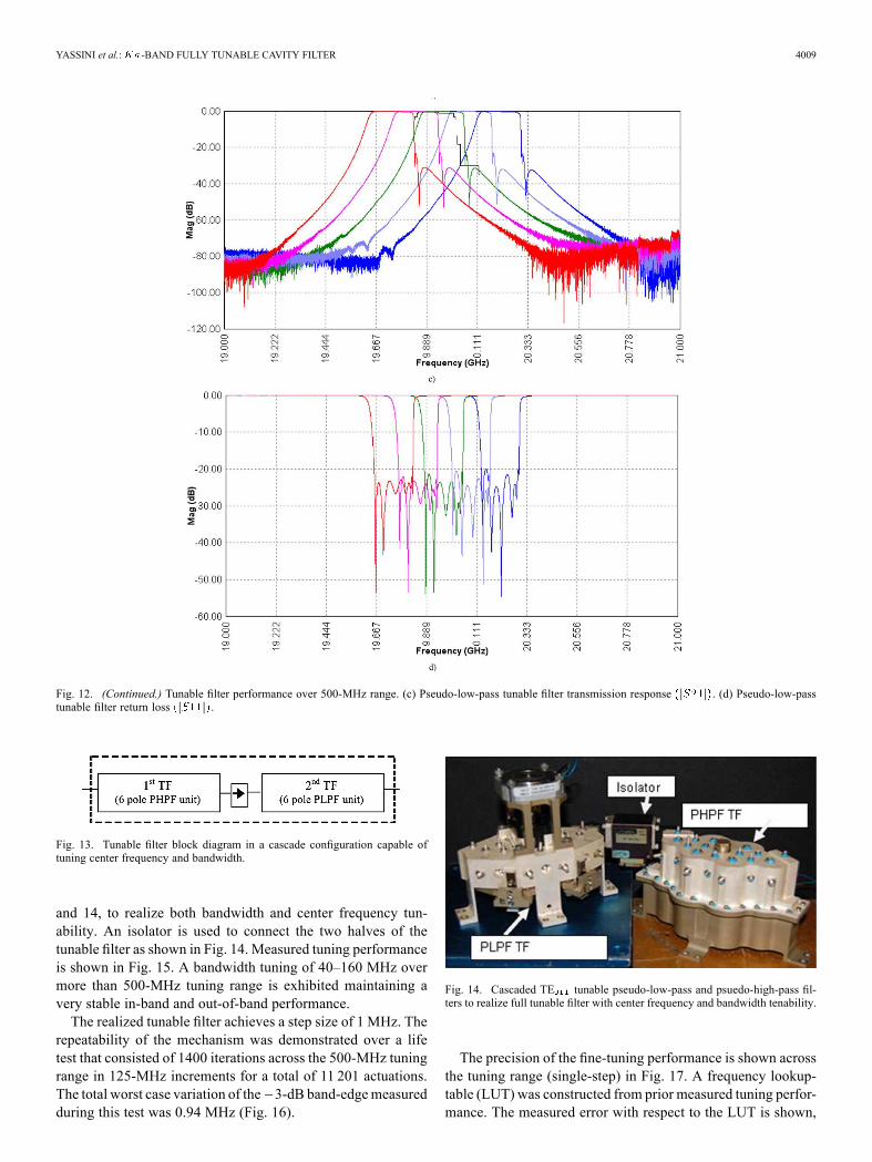
Fig. 12. (Continued.) Tunable filter performance over 500-MHz range. (c) Pseudo-low-pass tunable filter transmission response . (d) Pseudo-low-passtunable filter return loss .
Fig. 13. Tunable filter block diagram in a cascade configuration capable oftuning center frequency and bandwidth.
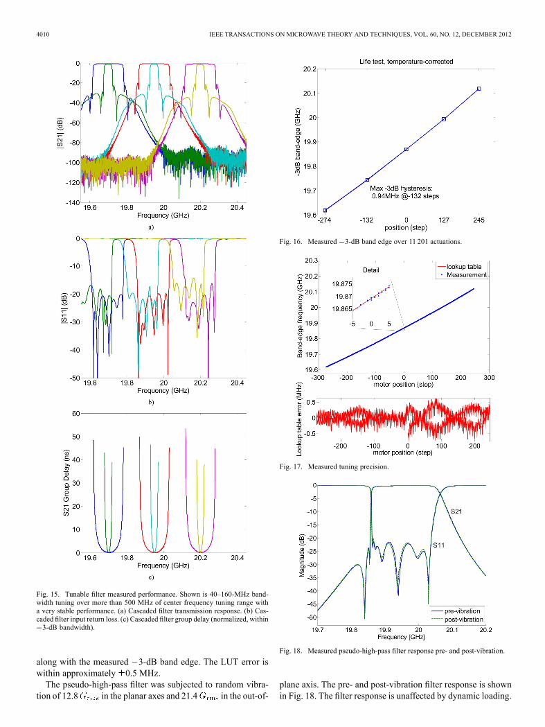
and 14, to realize both bandwidth and center frequency tun-ability. An isolator is used to connect the two halves of thetunable filter as shown in Fig. 14. Measured tuning performanceis shown in Fig. 15. A bandwidth tuning of 40–160 MHz overmore than 500-MHz tuning range is exhibited maintaining avery stable in-band and out-of-band performance.The realized tunable filter achieves a step size of 1 MHz. The
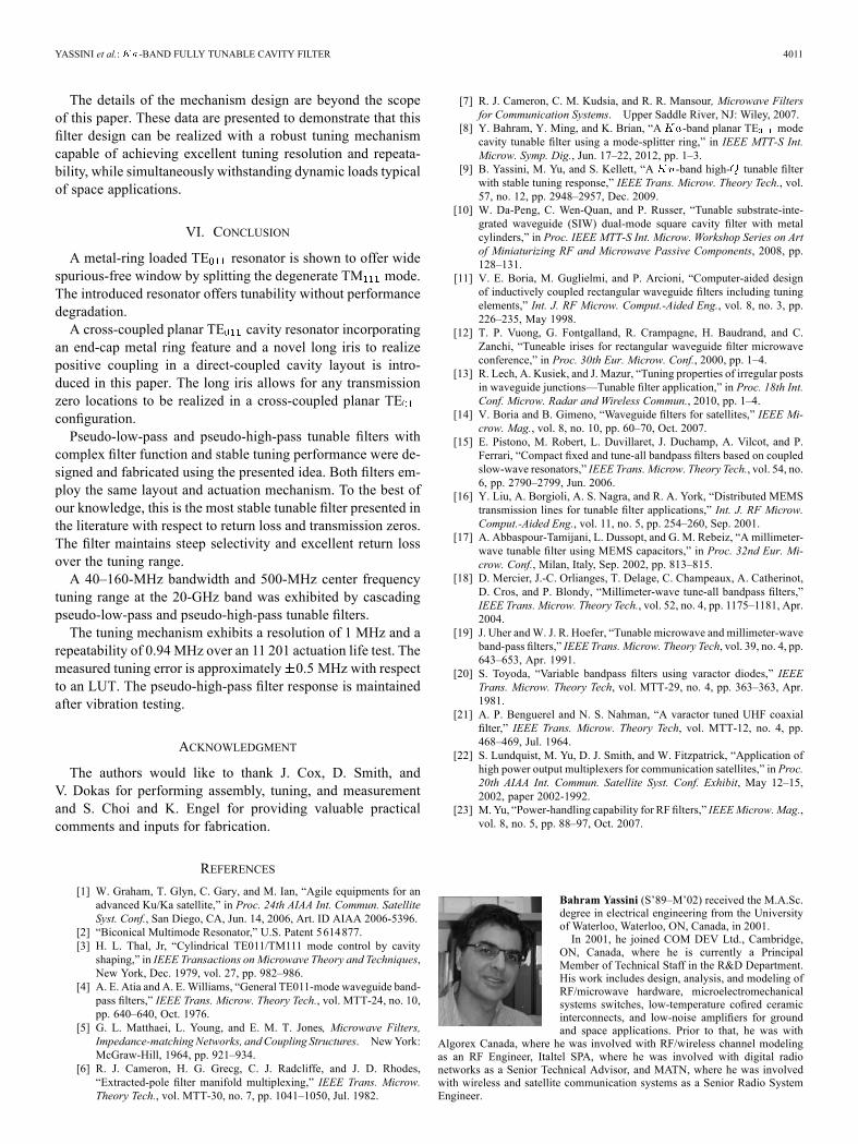
repeatability of the mechanism was demonstrated over a lifetest that consisted of 1400 iterations across the 500-MHz tuningrange in 125-MHz increments for a total of 11 201 actuations.The total worst case variation of the 3-dB band-edgemeasuredduring this test was 0.94 MHz (Fig. 16).
Fig. 14. Cascaded TE tunable pseudo-low-pass and psuedo-high-pass fil-ters to realize full tunable filter with center frequency and bandwidth tenability.
The precision of the fine-tuning performance is shown acrossthe tuning range (single-step) in Fig. 17. A frequency lookup-table (LUT) was constructed from prior measured tuning perfor-mance. The measured error with respect to the LUT is shown,
4010 IEEE TRANSACTIONS ON MICROWAVE THEORY AND TECHNIQUES, VOL. 60, NO. 12, DECEMBER 2012
Fig. 15. Tunable filter measured performance. Shown is 40–160-MHz band-width tuning over more than 500 MHz of center frequency tuning range witha very stable performance. (a) Cascaded filter transmission response. (b) Cas-caded filter input return loss. (c) Cascaded filter group delay (normalized, within3-dB bandwidth).
along with the measured 3-dB band edge. The LUT error iswithin approximately 0.5 MHz.The pseudo-high-pass filter was subjected to random vibra-
tion of 12.8 in the planar axes and 21.4 in the out-of-
Fig. 16. Measured 3-dB band edge over 11 201 actuations.
Fig. 17. Measured tuning precision.
Fig. 18. Measured pseudo-high-pass filter response pre- and post-vibration.
plane axis. The pre- and post-vibration filter response is shownin Fig. 18. The filter response is unaffected by dynamic loading.
YASSINI et al.: -BAND FULLY TUNABLE CAVITY FILTER 4011
The details of the mechanism design are beyond the scopeof this paper. These data are presented to demonstrate that thisfilter design can be realized with a robust tuning mechanismcapable of achieving excellent tuning resolution and repeata-bility, while simultaneously withstanding dynamic loads typicalof space applications.
VI. CONCLUSION
A metal-ring loaded TE resonator is shown to offer widespurious-free window by splitting the degenerate TM mode.The introduced resonator offers tunability without performancedegradation.A cross-coupled planar TE cavity resonator incorporating
an end-cap metal ring feature and a novel long iris to realizepositive coupling in a direct-coupled cavity layout is intro-duced in this paper. The long iris allows for any transmissionzero locations to be realized in a cross-coupled planar TEconfiguration.Pseudo-low-pass and pseudo-high-pass tunable filters with
complex filter function and stable tuning performance were de-signed and fabricated using the presented idea. Both filters em-ploy the same layout and actuation mechanism. To the best ofour knowledge, this is the most stable tunable filter presented inthe literature with respect to return loss and transmission zeros.The filter maintains steep selectivity and excellent return lossover the tuning range.A 40–160-MHz bandwidth and 500-MHz center frequency
tuning range at the 20-GHz band was exhibited by cascadingpseudo-low-pass and pseudo-high-pass tunable filters.The tuning mechanism exhibits a resolution of 1 MHz and a
repeatability of 0.94 MHz over an 11 201 actuation life test. Themeasured tuning error is approximately 0.5 MHz with respectto an LUT. The pseudo-high-pass filter response is maintainedafter vibration testing.
ACKNOWLEDGMENT
The authors would like to thank J. Cox, D. Smith, andV. Dokas for performing assembly, tuning, and measurementand S. Choi and K. Engel for providing valuable practicalcomments and inputs for fabrication.
REFERENCES
[1] W. Graham, T. Glyn, C. Gary, and M. Ian, “Agile equipments for anadvanced Ku/Ka satellite,” in Proc. 24th AIAA Int. Commun. SatelliteSyst. Conf., San Diego, CA, Jun. 14, 2006, Art. ID AIAA 2006-5396.
[2] “Biconical Multimode Resonator,” U.S. Patent 5 614 877.[3] H. L. Thal, Jr, “Cylindrical TE011/TM111 mode control by cavity
shaping,” in IEEE Transactions on Microwave Theory and Techniques,New York, Dec. 1979, vol. 27, pp. 982–986.
[4] A. E. Atia and A. E.Williams, “General TE011-mode waveguide band-pass filters,” IEEE Trans. Microw. Theory Tech., vol. MTT-24, no. 10,pp. 640–640, Oct. 1976.
[5] G. L. Matthaei, L. Young, and E. M. T. Jones, Microwave Filters,Impedance-matching Networks, and Coupling Structures. NewYork:McGraw-Hill, 1964, pp. 921–934.
[6] R. J. Cameron, H. G. Grecg, C. J. Radcliffe, and J. D. Rhodes,“Extracted-pole filter manifold multiplexing,” IEEE Trans. Microw.Theory Tech., vol. MTT-30, no. 7, pp. 1041–1050, Jul. 1982.
[7] R. J. Cameron, C. M. Kudsia, and R. R. Mansour, Microwave Filtersfor Communication Systems. Upper Saddle River, NJ: Wiley, 2007.
[8] Y. Bahram, Y. Ming, and K. Brian, “A -band planar TE modecavity tunable filter using a mode-splitter ring,” in IEEE MTT-S Int.Microw. Symp. Dig., Jun. 17–22, 2012, pp. 1–3.
[9] B. Yassini, M. Yu, and S. Kellett, “A -band high- tunable filterwith stable tuning response,” IEEE Trans. Microw. Theory Tech., vol.57, no. 12, pp. 2948–2957, Dec. 2009.
[10] W. Da-Peng, C. Wen-Quan, and P. Russer, “Tunable substrate-inte-grated waveguide (SIW) dual-mode square cavity filter with metalcylinders,” in Proc. IEEE MTT-S Int. Microw. Workshop Series on Artof Miniaturizing RF and Microwave Passive Components, 2008, pp.128–131.
[11] V. E. Boria, M. Guglielmi, and P. Arcioni, “Computer-aided designof inductively coupled rectangular waveguide filters including tuningelements,” Int. J. RF Microw. Comput.-Aided Eng., vol. 8, no. 3, pp.226–235, May 1998.
[12] T. P. Vuong, G. Fontgalland, R. Crampagne, H. Baudrand, and C.Zanchi, “Tuneable irises for rectangular waveguide filter microwaveconference,” in Proc. 30th Eur. Microw. Conf., 2000, pp. 1–4.
[13] R. Lech, A. Kusiek, and J. Mazur, “Tuning properties of irregular postsin waveguide junctions—Tunable filter application,” in Proc. 18th Int.Conf. Microw. Radar and Wireless Commun., 2010, pp. 1–4.
[14] V. Boria and B. Gimeno, “Waveguide filters for satellites,” IEEE Mi-crow. Mag., vol. 8, no. 10, pp. 60–70, Oct. 2007.
[15] E. Pistono, M. Robert, L. Duvillaret, J. Duchamp, A. Vilcot, and P.Ferrari, “Compact fixed and tune-all bandpass filters based on coupledslow-wave resonators,” IEEE Trans. Microw. Theory Tech., vol. 54, no.6, pp. 2790–2799, Jun. 2006.
[16] Y. Liu, A. Borgioli, A. S. Nagra, and R. A. York, “Distributed MEMStransmission lines for tunable filter applications,” Int. J. RF Microw.Comput.-Aided Eng., vol. 11, no. 5, pp. 254–260, Sep. 2001.
[17] A. Abbaspour-Tamijani, L. Dussopt, and G. M. Rebeiz, “A millimeter-wave tunable filter using MEMS capacitors,” in Proc. 32nd Eur. Mi-crow. Conf., Milan, Italy, Sep. 2002, pp. 813–815.
[18] D. Mercier, J.-C. Orlianges, T. Delage, C. Champeaux, A. Catherinot,D. Cros, and P. Blondy, “Millimeter-wave tune-all bandpass filters,”IEEE Trans. Microw. Theory Tech., vol. 52, no. 4, pp. 1175–1181, Apr.2004.
[19] J. Uher andW. J. R. Hoefer, “Tunable microwave and millimeter-waveband-pass filters,” IEEE Trans. Microw. Theory Tech, vol. 39, no. 4, pp.643–653, Apr. 1991.
[20] S. Toyoda, “Variable bandpass filters using varactor diodes,” IEEETrans. Microw. Theory Tech, vol. MTT-29, no. 4, pp. 363–363, Apr.1981.
[21] A. P. Benguerel and N. S. Nahman, “A varactor tuned UHF coaxialfilter,” IEEE Trans. Microw. Theory Tech, vol. MTT-12, no. 4, pp.468–469, Jul. 1964.
[22] S. Lundquist, M. Yu, D. J. Smith, and W. Fitzpatrick, “Application ofhigh power output multiplexers for communication satellites,” in Proc.20th AIAA Int. Commun. Satellite Syst. Conf. Exhibit, May 12–15,2002, paper 2002-1992.
[23] M.Yu, “Power-handling capability for RF filters,” IEEEMicrow.Mag.,vol. 8, no. 5, pp. 88–97, Oct. 2007.
Bahram Yassini (S’89–M’02) received the M.A.Sc.degree in electrical engineering from the Universityof Waterloo, Waterloo, ON, Canada, in 2001.In 2001, he joined COM DEV Ltd., Cambridge,
ON, Canada, where he is currently a PrincipalMember of Technical Staff in the R&D Department.His work includes design, analysis, and modeling ofRF/microwave hardware, microelectromechanicalsystems switches, low-temperature cofired ceramicinterconnects, and low-noise amplifiers for groundand space applications. Prior to that, he was with
Algorex Canada, where he was involved with RF/wireless channel modelingas an RF Engineer, Italtel SPA, where he was involved with digital radionetworks as a Senior Technical Advisor, and MATN, where he was involvedwith wireless and satellite communication systems as a Senior Radio SystemEngineer.
4012 IEEE TRANSACTIONS ON MICROWAVE THEORY AND TECHNIQUES, VOL. 60, NO. 12, DECEMBER 2012
Ming Yu (S’90–M’93–SM’01–F’09) received thePh.D. degree in electrical engineering from theUniversity of Victoria, Victoria, BC, Canada, in1995.In 1993, while working on his doctoral disserta-
tion part-time, he joined COMDEVLtd., Cambridge,ON, Canada, as a Member of Technical Staff. He wasinvolved in designing passive microwave/RF hard-ware from 300 MHz to 60 GHz for both space- andground-based applications. He was also a principaldeveloper of a variety of COM DEV’s core design
and tuning software for microwave filters and multiplexers, including computeraide tuning software in 1994 and fully automated robotic diplexer tuning systemin 1999. His varied experience also includes being the Manager of Filter/Mul-tiplexer Technology (Space Group) and Staff Scientist of Corporate Researchand Development (R&D). He is currently the Chief Scientist and Director ofthe R&D Department, COM DEV Ltd., where he is responsible for overseeingthe development of company R&D Roadmap and next-generation products andtechnologies, including high-frequency and high-power engineering, electro-magnetic-based computer-aided design and tuning for complex and large prob-lems, and novel miniaturization techniques for microwave networks. He is alsoan Adjunct Professor with the University of Waterloo, ON, Canada. He holdsNSERC Discovery Grant from 2004 to 2015 with the University of Waterloo.He has authored or coauthored over 100 publications and numerous proprietaryreports. He holds eight patents with six more pending.Dr. Yu is an IEEE Distinguished Microwave Lecturer from 2010 to 2012. He
has been the IEEE Microwave Theory and Techniques Society (MTT-S) Filtercommittee Chair (MTT-8) since 2010 and served as Chair of TPC-11. He isan associate editor of the IEEE TRANSACTIONS ON MICROWAVE THEORY ANDTECHNIQUES. He was the recipient of the 1995 and 2006 COM DEV Achieve-ment Award for the development a computer-aided tuning algorithms and sys-tems for microwave filters and multiplexers.
Brian F. Keats received the B.A.Sc. degree in me-chanical engineering, M.A.Sc. degree in electricaland computer engineering, and Ph.D. degree fromthe University of Waterloo, Waterloo, ON, Canada,in 2001. 2003, and 2007, respectively.Upon completion of his studies, he joined COM
DEV Ltd., Cambridge, ON, Canada, as a Post-Doc-toral Fellow, where he has been involved in the de-sign, development, and testing of a variety of prod-ucts including temperature-compensated filters, tun-able filters, and RF switches. He is currently a Senior
Member of the Technical Staff with the R&D Department and an Adjunct Lec-turer at the University of Waterloo, Waterloo, ON, Canada.