4000 2 slot modular instrument€¦ · 0.5/1 plc 1.6/1.6 100 ms 12 200 ms 22 4000 2 slot modular...
TRANSCRIPT
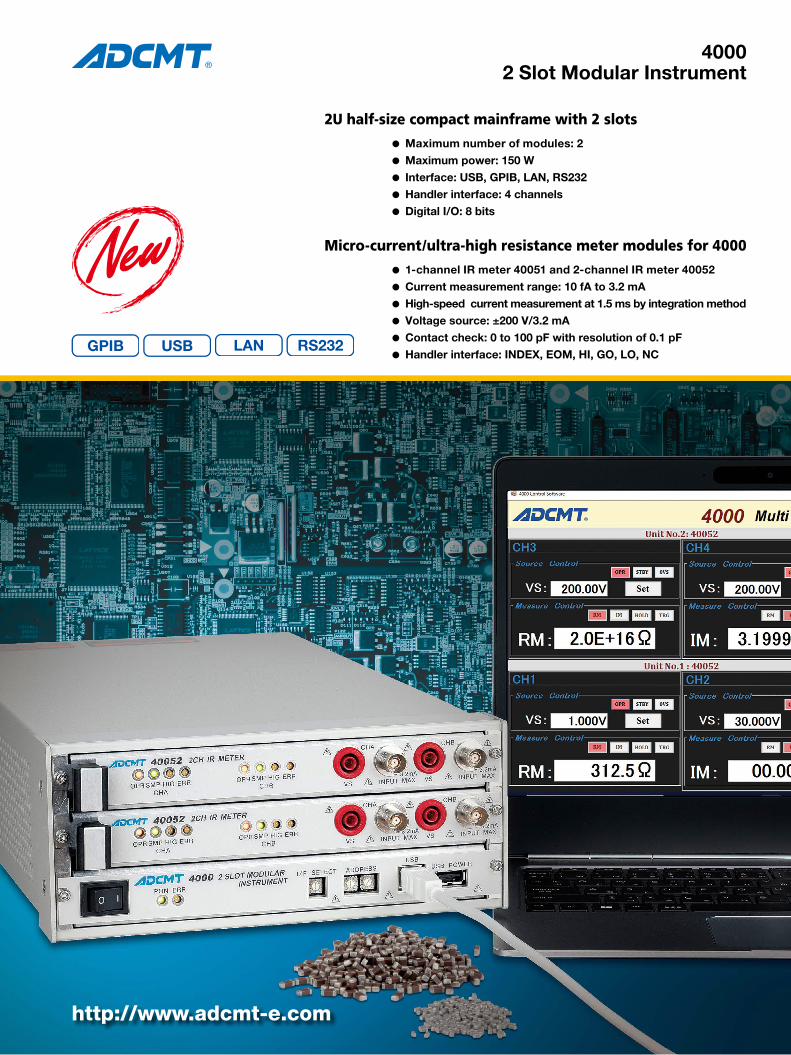
40002 Slot Modular Instrument
2U half-size compact mainframe with 2 slots
Micro-current/ultra-high resistance meter modules for 4000
l Maximum number of modules: 2l Maximum power: 150 Wl Interface: USB, GPIB, LAN, RS232l Handler interface: 4 channelsl Digital I/O: 8 bits
l 1-channel IR meter 40051 and 2-channel IR meter 40052l Current measurement range: 10 fA to 3.2 mAl High-speed current measurement at 1.5 ms by integration methodl Voltage source: ±200 V/3.2 mAl Contact check: 0 to 100 pF with resolution of 0.1 pFl Handler interface: INDEX, EOM, HI, GO, LO, NC
http://www.adcmt-e.com
LAN RS232

2 SLOT MODULAR INSTRUMENT2
4000 Rear Panel
4000 Front Panel
[Handler Interface Timing]
[Measurement time]
Handler interface timing and measurement time under the conditions of DC measurement mode by external trigger
INDEX and EOM times in DC mode (Td=0.05 ms)
INDEX and EOM times in fixed sweep mode: DC mode + 0.1 ms + Hold time (Th)
Measurement time Typical value Ti=1 ms
INDEX time(From trigger input to falling edge of /INDEX)
integration time (Ti)+αms 1.5 ms
Contact check ON +1.5 ms 3.0 ms
EOM time(From trigger input to falling edge of /EOM)
/INDEX + 0.25 ms 1.75 ms
Resistance measurement +0.06 ms 1.81 ms
Comparison judgment +0.05 ms 1.86 ms
Ti α1/2/5 ms 0.5/0.6/0.7
0.5/1 PLC 1.6/1.6
100 ms 12
200 ms 22
4000 2 Slot Modular Instrument
The 4000 is a 2-slot modular instrument of 2U half-size mainframe to which 2 units of 0.7U half-size modules can be installed.It is equipped with various interfaces; USB, GPIB, LAN and RS232, making it possible to build inspection systems for R&D or production lines of electronics components by connecting to a personal computer or programmable con-troller.In addition, the 4-channel handler interface allows you timing control with automatic machines, and device selec-tion according to measurement and judgment results by the modules.In inspection lines, you can easily perform system setup or maintenance of modules that are mounted on system racks without removal such as module replacement, operation check via USB on the front panel.Moreover, by using the digital I/O of 8 bits having a 5 V/200 mA power supply, easy relay control and signal generation are available.
40051/40052 IR Meter Unit
The 40051 and 40052 IR meter units are to be mounted into the 2-slots modular instrument 4000.The 1-channel 40051 and 2-channel 40052 are integration-method IR meters, suitable for current measurement of high-capacity samples such as capacitors.The 40051 or 40052 is capable of current measurement ranging from 10 fA to 3.2 mA and is equipped with a DC voltage generator of ±200 V/3.2 mA. So, its voltage source current measurement function makes it possible resistance measurement of between 312 Ω to 2×10¹⁶ Ω.In addition, it has a contact check function (C.CHK) by ca-pacity (C) measurement to judge the contact status of high-resistance samples.Moreover, the 40051 or 40052 is equipped with the handler interface to be controlled from automatic machines in pro-duction lines.
/TIGGER
ICV current measurement
Contact check execution
Math operation and judgment
/INDEX
/EOM
/HI, /GO, /LO, /NC
Td (measurement delay)
Rm operation, comparison judgment
Handler interface CH1 to CH4 Digital I/O interface
USB connector
RS232 connector
LAN connector
LED indicator
I/F SELECT switch USB interface
Address switch
USB POWER interface
GPIB connector
LED indicatorPulling side handle

3
2 Slot Modular Instrument 4000 Specifications
Indicators (LEDs)PON: Power ONERR: Error (Fan stopped, self-test error)
Interface Specifications:USB interface: USB 2.0 Full-Speed(Front/Rear) Connector: Type BUSB POWER: Power: +5 V/1 A max(Front) Connector: Type AGPIB interface: Compliant to IEEE-488.1-1978(Rear) Interface functions: SH1, AH1, T6, L4, SR1, RL1, PP0, DC1, DT1, C0, E2 Connector: Amphenol 24-pinLAN interface: Compliant to IEEE802.3 (10BASE-T, 100BASE-TX)(Rear) Connector: RJ-45RS232 interface: Standard: RS232 (EIA232) Baudrate: Up to 19200 Connector: D-Sub 9 pinHandler interface: Input: /TRIGGER, INTERLOCK(Rear, 4 channels) Output: /INDEX, /EOM, /COMPLETE, /HI, /GO, /LO, /NO.CONTACT, /VS LIMIT, /ALARM Input level: Hi; +4 to +30 V, Lo; 0 to +0.8 V Output level: Hi; 30 V max, Lo; 0.8V max, sink; 50 mA max Connector: D-Sub 15 pinDigital I/O: Input/Output: 8 bits(Rear) Input level: Hi; +4 to +30 V, Lo; 0 to +0.8 V Output level: Hi; 30 V max, Lo; 0.8 V max, sink: 50 mA max Power supply: +5 V/200 mA Connector: D-Sub 15 pin
General SpecificationsOperation environment: Temperature; 0°C to +50°C Relative humidity; 85% or less with no condensationStorage environment: Temperature; -25°C to +70°C Relative humidity; 85% or less with no condensationPower supply: 100 VAC to 240 VACPower frequency: 50 Hz/60 HzPower consumption Mainframe with units: 150 VA or less (depending on the units) Mainframe only (without unit): 35 VA or lessDimensions: Approx. 212 (W) × 88 (H) × 400 (D) mm (not including feet)Mass: 3.3 kg or less (not including units and feet)
Supplied accessories
Optional accessories
IR Meter Unit 40051/40052 SpecificationsAll accuracy specifications are guaranteed for one year at a temperature of 23±5°C and a relative humidity not exceeding 70%.
Measurement Functions1. DC current measurementIntegration time: 200 ms
Input voltage drop: ±1.5 mV + (50 Ω × measurement current) or lessInput bias current: 100 fA or lessSettling time: Same time as the integration time (until the specified accuracies are satisfied.)Maximum allowable input current: 3.2 mANMRR: 60 dB or more (at 50 Hz/60 Hz ±0.08%)*1 At temperature of 0 to 50°C and relative humidity of 70% or less
±50 fA/°C is added to the digits item between +40°C and +50°C.
2. Resistance value display (RM operation)(Resistance value obtained by "voltage source value/current measurement value")Measurement accuracy:
±((rdg item of current measurement range + setting item of voltage source range) + (digits item of voltage source range × resolution × 100/source voltage value) + (resistance reading value × digits item of current measurement range ×
resolution × 100/source voltage value))% + 50 ΩTemperature coefficient:
±((rdg item of current measurement range + setting item of voltage source range) + (digits item of voltage source range × resolution × 100/source voltage value) + (resistance reading value × digits item of current measurement range ×
resolution × 100/source voltage value))%/°C + 5 Ω/°CMaximum display: 1 to 5 digits (1 to 9.9999)
Example of integration time of 200 ms and input voltage of ±100 V
Rm: resistance reading value
3. Additional errors in DC current measurementAdditional error for each integration time other than 200 ms. For each integration time (IT), the following accuracies are added to the accuracies of the integration time of 200 ms
±(% of reading + digits)
PLC: Power Line Cycle (50 Hz: 20 ms, 60 Hz: 16.67 ms)
Integration time by ICV method (Ti) against setting integration time (IT)
* The expressions such as "2 ms × 2" indicate that measurement is performed by using the
average of two measurements with integration time of 2ms.
Source Functions Voltage source
Settling time: 3.5 ms or less (until the final value ±0.1% is reached.)Maximum allowable input voltage: ±200 V peakMaximum capacitance load: 1000 μF
Model Quantity NameA01402 1 Power supply cable
Model NameA02263 JIS standard, rack mount set (single)
A02264 JIS standard, rack mount set (twin)
A02463 EIA standard, rack mount set (single)
A02464 EIA standard, rack mount set (twin)
A02039 Panel mount set (single)
A02040 Panel mount set (twin)
Range Maximum display Resolution
Accuracy±(% of reading + digits) Temperature coefficient*1
±(ppm of reading + digits)/°CAt 23°C±5°C,
for one yearWithin ±3°C for 24 hrs after INTCAL
300 pA 319.999 pA 1 fA 0.65 + 120 0.4 + 100 600 + 15
3 nA 3.19999 nA 10 fA 0.65 + 35 0.4 + 35 600 + 2
30 nA 31.9999 nA 100 fA 0.5 + 25 0.3 + 25 600 + 1
300 nA 319.999 nA 1 pA 0.5 + 25 0.3 + 25 600 + 0.5
3 μA 3.19999 μA 10 pA 0.5 + 25 0.3 + 25 600 + 1
30 μA 31.9999 μA 100 pA 0.5 + 25 0.3 + 25 600 + 0.5
300 μA 319.999 μA 1 nA 0.5 + 21 0.3 + 21 600 + 0.5
3 mA 3.19999 mA 10 nA 0.5 + 22 0.35 + 22 600 + 0.5
Current range
Measurement range [Ω]
Accuracy
At 23°C ±5°C, for one year Within ±3°C for 24 hrs after INTCAL
300 pA 3.12×10¹¹ to 1×10¹⁶ 0.68+0.05+1.2×10⁻¹³ Rm+50 Ω 0.43+0.05+1×10-13 Rm+50 Ω
3 nA 3.12×10¹⁰ to 1×10¹⁵ 0.68+0.05+3.5×10⁻¹³ Rm+50 Ω 0.43+0.05+3.5×10⁻¹³ Rm+50 Ω
30 nA 3.12×10⁹ to 1×10¹⁴ 0.53+0.05+2.5×10⁻¹² Rm+50 Ω 0.33+0.05+2.5×10⁻¹² Rm+50 Ω
300 nA 3.12×10⁸ to 1×10¹³ 0.53+0.05+2.5×10⁻¹¹ Rm+50 Ω 0.33+0.05+2.5×10⁻¹¹ Rm+50 Ω
3 μA 3.12×10⁷ to 1×10¹² 0.53+0.05+2.5×10⁻¹⁰ Rm+50 Ω 0.33+0.05+2.5×10⁻¹⁰ Rm+50 Ω
30 μA 3.12×10⁶ to 1×10¹¹ 0.53+0.05+2.5×10⁻⁹ Rm+50 Ω 0.33+0.05+2.5×10⁻⁹ Rm+50 Ω
300 μA 3.12×10⁵ to 1×10¹⁰ 0.53+0.05+2.1×10⁻⁸ Rm+50 Ω 0.33+0.05+2.1×10⁻⁸ Rm+50 Ω
3 mA 3.12×10⁴ to 1×10⁹ 0.53+0.05+2.2×10⁻⁷ Rm+50 Ω 0.38+0.05+2.2×10⁻⁷ Rm+50 Ω
Integration time (IT) 1 ms, 2 ms 5 ms 0.5 PLC 1 PLC 100 ms
Range rdg digits rdg digits rdg digits rdg digits rdg digits
300 pA 0 30 0 30 0 30 0 30 0 30
3 nA 0 265 0 265 0 165 0 65 0 15
30 nA 0.15 125 0.15 55 0.15 25 0.15 5 0 5
300 nA 0.15 25 0 55 0 25 0 5 0 0
3 μA 0 25 0 25 0 5 0 0 0 0
30 μA 0 5 0 55 0 25 0 0 0 0
300 μA 0 25 0 25 0 5 0 0 0 0
3 mA 0 15 0 5 0 5 0 2 0 0
RangeSetting integration time (IT)
1 ms 2 ms 5 ms 0.5 PLC 1 PLC 100 ms 200 ms
300 pA 100 ms 200 ms
3 nA 5 ms 5 ms 0.5 PLC 1 PLC 100 ms 200 ms
30 nA to 30 μA 1 ms 2 ms 5 ms 0.5 PLC 1 PLC 100 ms 200 ms
300 μA 1 ms 2 ms 5 ms 0.5 PLC 1 PLC 1 PLC×4 1 PLC×8
3 mA 1 ms 2 ms 1 ms×2 2 ms×2 2 ms×4 2 ms×20 1 ms×40
Range Maximum display Resolution Accuracy
±(% of setting + digits)Temperature coefficient
±(ppm of setting + digits)/°C
30 V ±32.000 V 1 mV 0.03 + 6 20 + 0.5
200 V ±200.00 V 10 mV 0.03 + 5 20 + 0.5

© 2019 ADC CORPORATION Printed in Japan 4000-NP2 June '19 A
Head Office (R&D Center)
East Branch (Sales Dept.)Okabe-building, 3-515, Onari-cho, Omiya-ku, Saitama-shi,Saitama 330-0852, JapanPhone: +81-48-651-4433 Fax: +81-48-651-4432
E-mail : [email protected] URL : http://www.adcmt-e.com
77-1, Miyako Namegawa-machi, Hiki-gun,Saitama 355-0812, JapanPhone: +81-493-56-4433 Fax: +81-493-57-1092
Maximum input voltage/current between terminals:
*2 The internal shield is connected to the LO terminal.
*3 The chassis is connected to the LO or the VS terminal depending on the relay.
200 V at the terminal where no connection is made.
Indicators (LEDs)OPR Operate (output ON)SMP Sampling indicatorHIG VS-GND connecting statusERR Error (VS LIMIT, self test error, unit error)
General SpecificationsOperation environment: Temperature; 0°C to +50°C Relative humidity; 85% or less with no condensationStorage environment: Temperature; -25°C to +70°C Relative humidity; 85% or less with no condensationWarm-up time 60 minutes or longer (until the specified accuracies are satisfied.)Power consumption 40051: 7.5 VA or less, 40052: 15 VA or lessDimensions: Approx. 207 (W) × 26 (H) × 365 (D) mmMass: 40051: 0.8 kg or less, 40052: 1.0 kg or les
Optional accessories
Output noisePeak to peak values under the following load conditions
Current limit
Setting TimeSource delay time (Tds), Period (measurement cycle) (Tp), Measurement delay time (Td):
Hold time (Th):
Source and Measurement FunctionsSource mode: DC mode, Sweep modeSweep type: Fixed level sweepSweep repeat count: 1 to 1,000Maximum number of sweep steps: 10,000 steps/channelMeasurement data buffer memory: 10,000 data/channel
Comparison operation: HI, GO, LO
Contact check function:Measurement range: 0 to 100 pFMeasurement frequency: 500 kHz, 315 kHzResolution: 0.1 pF/500 kHz, 0.2 pF/315 kHzOpen Cal: 0 pF to 90 pFMaximum cable length: TRIAX cable 3 m
Measurement terminal: INPUT TRIAXIAL connector LO Safety socket (40051 only)Voltage output terminal: VS Safety socket
Range Load resistance DC to 100 Hz DC to 10 kHz
30 V No load or maximum load
1 mV 3 mV
200 V 3 mV 10 mV
RangeMaximum
displayResolution
Accuracy±(% of setting + digits)
Temperature coefficient±(ppm of setting + digits) / ºC
Setting range
3 mA 3.200 mA 1 μA 0.1 + 23 30 + 0.6 0.03 mA to 3.200 mA
Setting time Resolution Setting accuracy
0.030 ms to 60.000 ms (Source delay)0.100 ms to 60.000 ms (Period)0.050 ms to 60.000 ms (Measurement delay)
1 μs
±(0.1% + 10 μs)60.01 ms to 600.00 ms 10 μs
600.1 ms to 6000.0 ms 100 μs
6001 ms to 59998 ms 1 ms
Setting time Resolution Setting accuracy
0 ms to 6000.0 ms 0.1 ms ±(2% + 2 ms)
Model Description
A01009 TRIAX- TRIAX cable
A01239 High-voltage TRIAX- TRIAX cable
A01010 TRIAX-alligator cable
A01011 TRIAX- BNC cable
A04201 TRIAX J- TRIAX J adapter
A04202 TRIAX-J - BNC-P 1 adapter (inside-outside)
A04203 TRIAX-J - BNC-P 2 adapter (outside-outside)
A04204 BNC-J - TRIAX-P 1 adapter (outside-inside)
A04205 BNC-J - TRIAX-P 2 adapter ((outside-(inside+outside))
A04206 TRIAX-J - BNC-P 3 adapter ((inside+outside)-outside)
A04207 BNC-J - M-P
A04208 TRIAX-J receptacle
Internal shield VS LO Chassis
INPUT3.2 mA
3.2 mA 3.2 mA 3.2 mA
Internal shield 200 V short *2 *3
VS 200 V *3
LO *3
• Please read through the operation manual carefully before using the products.• All specifications are subject to change without notice.