4.0 rtos implementation part ii mohamad fauzi bin zakaria [email protected] beh30802 :: real-time...
TRANSCRIPT

4.0 RTOS IMPLEMENTATIONPART II
Mohamad Fauzi bin [email protected]
BEH30802 :: REAL-TIME EMBEDDED SYSTEM

ChibiOS/RT – Part II
4.5. Introduction to Serial Communication Protocol
4.6. Universal Asynchronous Receiver Transmitter (UART)
4.7. Inter-integrated Communication (I2C)
4.8. Serial Peripheral Interface (SPI)

OVERVIEW
Serial
Receiver
Transmitter Parallel
Receiver
Transmitter
1 bit
1 word

SERIAL VS PARALLELSERIAL PARALLEL
COST Cheap Expensive
SPEED Slow Fast
TRANSMISSION AMOUNT
Single bit8 bits (8 data lines) Transmitter &
Receiver
TRANSMISSION LINES
One line to transmit one to receive
8 lines for simultaneous transmission
TRANSMISSION DISTANCE
LongShort distance
(synchronization)

DATA TRANSMISSION

SERIAL COMMUNICATION METHOD


IN-VEHICLE NETWORK

RS232 - UART
Signal level: TTL (direct) or RS232(needs line driver)
Was set by the Electronics Industries Association (EIA) in 1960, before the advent of TTL logic family.
Therefore, logic 1 is represented by “-3 to -25V”, and logic 0 is “+3 to +25V”. Two types of RS232 pins: DB-25 and DB-9. Most important pins are Tx, Rx, and
ground. To interface with microcontroller, we need line driver such as MAX232 (need
capacitors) or MAX233 (no capacitors).
Common baud rate: 9600 or11.2k bps

RS232 VS TTL
RS232
TTL

EXAMPLE OF TTL UART

INTER-INTEGRATED CIRCUIT (I2C)
Developed by Philips Semiconductor for TV sets in the 1980’s
I2C devices include EEPROMs, thermal sensors, and real-time clocks
Used as a control interface to signal processing devices that have separate data interfaces, e.g. RF tuners, video decoders and encoders, and audio processors.
Limited to about 10 feet for moderate speeds

I2C BUS CONFIGURATION
2-wire serial bus – Serial data (SDA) and Serial clock (SCL)
Half-duplex, synchronous, multi-master bus
No chip select or arbitration logic required
Lines pulled high via resistor

I2C PROTOCOLCommunication Speed (Data rate)1. Normal mode: 100 kHz2. Fast mode: 400 kHz3. Fast mode plus: 1MHz4. High-speed mode: 3.4MHz5. Ultra-fast mode: 5MHz

I2C TRADEOFFS
• Good for communication with on-board devices that are accessed occasionally.
• Easy to link multiple devices because of addressing scheme
• Cost and complexity do not scale up with the number of devices
Advantages
• The complexity of supporting software components can be higher than that of competing schemes (for example, SPI ).
Disadvantages

SERIAL PERIPHERAL INTERFACE (SPI)
Defined by Motorola on the MC68HCxx line of microcontrollers
Generally faster than I2C, capable of several Mbps
Applications:• Like I2C, used in EEPROM, Flash, and real time clocks• Better suited for “data streams”, i.e. ADC converters• Full duplex capability, i.e. communication between a codec
and digital signal processor

SPI BUS CONFIGURATION
Synchronous serial data link operating at full duplex
Master/slave relationship• MOSI – master data output, slave data input• MISO – master data input, slave data output2 data signals:• SCLK – clock• /SS – slave select (no addressing)2 control signals:
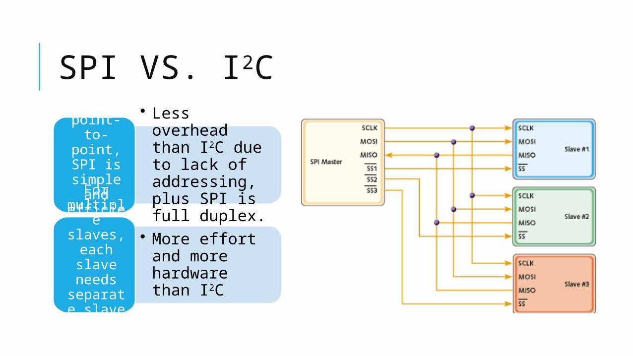
SPI VS. I2C• Less overhead
than I2C due to lack of addressing, plus SPI is full duplex.
For point-to-point, SPI is simple
and efficient
• More effort and more hardware than I2C
For multiple slaves, each slave needs
separate slave select signal

SPI PROTOCOL
Master and slave must agree on parameter pair
values in order to communicate
2 Parameters, Clock Polarity (CPOL) and Clock Phase (CPHA), determine
the active edge of the clock
CPOL CPHA Active edge
0 0 Rising
0 1 Falling
1 0 Falling
1 1 Rising

SPI PROTOCOL (CONT.)