4. small diameter wells - building & indoor … · consists of a slotted piece of tubing or...
TRANSCRIPT

Produced by: Natural Resources
Management and Environment
Department
Title: Self-help wells...
More details
4. Small diameter wells
4.1 Bored or augered wells
4.2 Driven wells
4.3 Jetted wells
4.4 Hydraulic percussion (also hollow rod method)
4.5 Percussion (also cable tool method)
4.6 Hydraulic rotary
4.7 Casing and screens
4.8 Methods for obtaining vertical reciprocating motion
4.9 Rope
4.10 Well development and finishing
4.11 Problem solving
4.1 Bored or augered wells
This method of excavation consists of shaving or cutting material from the bottom of the
hole by the rotation of a cylindrical tool with one or more cutting lips. The process is quite
analagous to boring a hole in wood or metal with an auger or drill. The excavated earth
normally feeds upward and is contained in the body of the auger where it remains until the
auger is emptied. The auger is both rotated and raised and lowered by means of a vertical
shaft which extends upward from the auger to a convenient point above ground level from
which it can be rotated. Rotation is frequently accomplished by human power applied to a
handle attached to the vertical shaft. However, the auger may be driven by other power
sources such as animal or engine power. In this case, the power source drives a horizontal
ring gear. Two projections extending upward from the ring gear drive a bar known as a
"kelly" which lies across a diameter of the ring. A square section of the auger shaft fits
through a square hole at the centre of the kelly bar which causes the auger shaft to rotate
with the kelly bar while allowing it vertical freedom.
Each time the auger is filled with excavated material, it must be brought out of the hole for
emptying. In order to accomplish this, the auger shaft must be divided into sections which
can be uncoupled and set aside.
Several types of earth augers have been used successfully for boring wells (Figure 3). The
cylindrical bucket auger is a sheet metal cylinder with an attachment for the auger shaft at
the top. The bottom has a helical form with a single cutting lip. It may be hinged and
latched, so that it can be opened for emptying. The two-bladed auger consists of two
cylindrical blades attached to the auger shaft. The blades are cut and bent at the bottom to
form cutting lips. This type of auger is frequently used for boring post holes.
Fig. 3. Earth augers. (a) cylindrical bucket auger
4. Small diameter wells http://www.fao.org/docrep/X5567E/x5567e05.htm#4.11 problem solving
1 of 36 7/28/2010 12:03 PM

Fig. 3. Earth augers. (b) two-bladed auger
Fig. 3. Earth augers. (c) helical auger
4. Small diameter wells http://www.fao.org/docrep/X5567E/x5567e05.htm#4.11 problem solving
2 of 36 7/28/2010 12:03 PM

Fig. 3. Earth augers. (d) tubular auger
4. Small diameter wells http://www.fao.org/docrep/X5567E/x5567e05.htm#4.11 problem solving
3 of 36 7/28/2010 12:03 PM

A third type of earth auger (Figure 4) has a spiral of helical form. This type of auger
normally has two cutting lips, one of which is mounted on the leading edge of the helix. It is
sold commercially for power boring of holes or for planting trees.
A fourth type of "auger" device (Figures 5 and 6) has been used by the author in sticky or
heavy clay soils where conventional augers with cutting lips did not function well. This
consists of a slotted piece of tubing or pipe with the lower end cut into a tooth and flared
configuration. The upper end was attached to a conventional auger shaft. This auger is
alternately rammed downward and then rotated. The downward motion causes soil to be
forced up inside the auger where it adheres and the rotation breaks this soil free from the
bottom of the hole. A small quantity of water may be maintained at the bottom of the hole
for lubrication.
Most types of augers work well on a wide variety of soils. The type used may depend
largely on what can be obtained or built locally. When selecting or building an auger,
several principles should be observed:
- the cutting lips or edge should cut a diameter slightly larger than the body of
the auger above them, so that the auger will not drag on the sides of the hole
- the cutting lips should be angled in such a way that only the cutting edge and
not the surface behind it comes into contact with the surface to be penetrated;
this improves penetration and reduces drag
- as the height to diameter ratio of an auger increases, the straightness of the
hole tends to increase (i.e. a tall, small diameter auger tends to bore a
straighter hole than a short, large diameter auger)
- the body of the auger must be capable of holding the excavated material until
the auger can be removed from the hole for emptying. Finely divided material
has a tendency to flow out of the auger if openings are too large. When the
water table is reached, augers cannot normally retain the cuttings and
deepening of the well must be carried out by one of the other methods
described. \
Fig. 4 Locally fabricated helical auger attached to pipe extension
Fig. 5 Locally fabricated cylindrical "auger" used in sticky soils
Drilling is accomplished by ramming downwards and then twisting. Auger teeth should be
flared outwards to give clearance between auger and hole. Smaller tool is for cleaning
compacted soil from the auger.
Fig. 6 Cylindrical auger with pipe extension and handle attached
Tripod is used to support auger during drilling.
Augers cannot normally penetrate stone. However, thin layers or small pieces of stone can
sometimes be pulverized or dislodged and removed by means of a percussion bit or a
spiral auger ("ram horn") made of steel rod in a form similar to a corkscrew. If the stone
can be penetrated or removed, boring can be continued. If not, a different process or new
location must be tried.
The necessity of emptying the auger each time it is filled places some practical limits on
the depth of augered holes. Since the sections of the auger shaft must be uncoupled each
time the auger is emptied, the time required for emptying increases with the depth of the
hole. To minimize the number of couplings, the lengths of auger shaft or "extensions"
4. Small diameter wells http://www.fao.org/docrep/X5567E/x5567e05.htm#4.11 problem solving
4 of 36 7/28/2010 12:03 PM

should be made as long as practical. Frequently, auger shafts are made from lengths of
water pipe which range in length from 6.1 to 6.4 metres (20-21 ft). Extensions (Figures 7
and 8) may be coupled by means of a socket attached to the top of each one. The bottom
of the next extension is inserted into this coupling and held there by a pin through the
socket. Normal threaded pipe couplings do not make satisfactory attachments, since they
wear under prolonged use. An overhead structure of some type is needed to steady the
long extensions and to ensure that they are maintained vertical during the drilling operation.
It is also convenient to lean the extensions against this structure when they are uncoupled.
The overhead structure for steadying and guiding the extensions might consist of a tripod
with a crosspiece between two legs (Figures 9 and 10) or of two vertical posts set in the
ground with a crosspiece between them. The handle or other device for rotating the auger
shaft should be designed to mount at any point along the extensions, so that it can be
maintained at a suitable working height (Figure 11).
Fig. 7 Auger extension and handle
Fig. 8 Coupling for auger extensions made from larger pipe and welded to the top of
an extension.
The succeeding extension is pinned in place by a 10 mm bolt. During coupling or
uncoupling the bottom of the coupling is supported by the notched board. The short length
of rod is inserted to prevent the extension from being accidentally dropped down the hole.
Fig. 9 Tripod used to support long auger extensions during drilling
4. Small diameter wells http://www.fao.org/docrep/X5567E/x5567e05.htm#4.11 problem solving
5 of 36 7/28/2010 12:03 PM

Fig. 10 Tripod used to support long auger extensions during drilling
Fig. 11 Drilling with a helical auger
Fig. 12 Reaming blade for enlarging hole attached to top of auger
After the approximate well location has been selected, the overhead support can be set up,
and the exact location determined by hanging a plumb line from the overhead auger guide.
A small starting hole for the auger can then be dug. It is important to get the auger starter
as close to vertical as possible.
The deepest hand augered well known to the author is approximately 38 metres (125 feet).
This well was bored by a crew of workers who were paid by the metre and was bored at a
very reasonable cost. However, under other economic conditions the practical limit for
hand boring may be less. When augering becomes too slow, it may be more practical to
continue with a different method.
Some earth augers may be equipped with a blade for reaming to the desired well diameter
(Figure 12). Boring an exploratory hole prior to digging a large diameter well may also be a
good investment where conditions are uncertain.
4.2 Driven wells
The driven well consists of a pointed perforated pipe or a pipe with a pointed well screen
attached which has been driven into an aquifer. The pipe with pointed well screen is driven
into place in much the same way a nail is driven into wood. Normally special pipe with thick
walls and specially designed couplings are used to resist the driving forces. Under suitable
conditions this method can yield a finished well in a very short time. While the well diameter
is normally small and the yield relatively low, a number of driven wells may be coupled
together and pumped with a single pump. Because driven wells are quick to construct, they
may be used as a temporary source of water and then be pulled up when no longer
4. Small diameter wells http://www.fao.org/docrep/X5567E/x5567e05.htm#4.11 problem solving
6 of 36 7/28/2010 12:03 PM

needed. Driven well points may be installed and used for dewatering an excavation during
construction. Unlike other well construction methods, material is merely forced aside and
not excavated by the driving process. This means that little is learned about the material
through which the well pipe passes. This kind of well can, however, be used for exploratory
purposes to determine static water level and rate of inflow versus drawdown. Hard
formations cannot be penetrated by this process. Barring impermeable strata the depth to
which such a well can be driven depends on the build-up of friction between the well pipe
and the material penetrated and the transmission of the force of the driver down the length
of pipe. Twenty-five to thirty metres (80-100 feet) would probably be a maximum. A driven
well point might be employed to finish a hole which had been excavated down to the water
table by some other method such as an auger.
Driving is normally accomplished by alternately raising and dropping a weight used as a
driver (Figure 13). The driver is guided on either the inside or the outside of the pipe
causing it to strike squarely and accurately. If the driver is designed to strike the upper end
of the pipe a driving cap is screwed onto the threads to protect them. Alternatively the
driver may be designed to strike a clamp made for that purpose around the outside of the
pipe. A long, thin driver which fits inside the pipe and which strikes a flat surface on the
inside of the well screen point may also be used. This latter technique eliminates
compressive loading on the pipe normally caused by driving and makes heavy drive pipe
unnecessary.
Fig. 13 Devices for well driving. (a) guided on outside of pipe
4. Small diameter wells http://www.fao.org/docrep/X5567E/x5567e05.htm#4.11 problem solving
7 of 36 7/28/2010 12:03 PM

Fig. 13 Devices for well driving. (b) guided on inside of pipe
Fig. 13 Devices for well driving. (c) driving on clamp
4. Small diameter wells http://www.fao.org/docrep/X5567E/x5567e05.htm#4.11 problem solving
8 of 36 7/28/2010 12:03 PM

Fig. 13 Devices for well driving. (d) driving on inside of point
4. Small diameter wells http://www.fao.org/docrep/X5567E/x5567e05.htm#4.11 problem solving
9 of 36 7/28/2010 12:03 PM

Well screens for driving must have sufficient strength to withstand the forces caused by the
driver and the abrasion of the material through which they pass. One common type (Figure
14a) consists of a perforated drive pipe fitted with a point. The perforated section of the
pipe is wrapped with a layer of brass screen of the desired fineness and the screen is
protected from damage by wrapping it with a layer of perforated brass sheet. Both layers
are soldered to the pipe. Another type of well screen (Figure 14b) is manufactured by
wrapping trapezoidal rod in a spiral around a set of round longitudinal rods placed in a
circular pattern with all intersections welded. This type of screen has the advantage of
having a high percentage of open area and a slot shape which cannot become wedged full
of fine sand particles.
Fig. 14 Drive points and screens. (a) perforated pipe with screen
Fig. 14 Drive points and screens. (b) spiral trapezoidal wire
4. Small diameter wells http://www.fao.org/docrep/X5567E/x5567e05.htm#4.11 problem solving
10 of 36 7/28/2010 12:03 PM

A drive point can be fabricated locally from pipe (Figure 15). The point is made by: (i)
flattening the end of the pipe to a gradual taper similar to the working end of a screwdriver
or cold chisel; (ii) cutting out a 'V notch from the corners of the flattened end to a point at
the middle of the pipe near where the taper starts; (iii) bringing the two resulting points
together to a single point; (iv) welding the two sides of the point together; and (v) filing or
grinding away any irregularities to yield a smooth point. If welding equipment is not
available the point can be forge-brazed or welded. A collar should be welded or riveted
above the point to increase the size of the hole to a diameter slightly greater than that of
the pipe couplings used. Alternatively, a point may be forged from solid steel and welded
or riveted to the end of pipe. In this case care should be taken to make a shoulder on the
back of the point which butts against the end of the pipe quite accurately and make the
largest diameter of the point greater than that of the pipe couplings to provide clearance.
Fig. 15 Drive point fabricated from pipe. (a) forming point on end of pipe
Fig. 15 Drive point fabricated from pipe. (b) alternative perforations and points
4. Small diameter wells http://www.fao.org/docrep/X5567E/x5567e05.htm#4.11 problem solving
11 of 36 7/28/2010 12:03 PM

Perforations may be made by drilling holes of the desired screen size or by making a
series of short diagonal hacksaw cuts (Figure 15b). In either case enough strength must be
retained in the pipe to permit driving. This can best be assured, in the case of the saw cuts,
by leaving several longitudinal strips unperforated. If larger perforations are made and
covered with screening of the desired mesh soldered around the pipe, the screening
should be protected from being slit or stripped back by: (i) wrapping and soldering sheet
metal with coarse perforations around it and (ii) having an outside diameter greater than
the outside diameter of the screening either on the point or on a collar attached to the pipe
below the screen.
If driving is attempted using ordinary pipe and couplings, shearing or stripping of the pipe
threads or breaking of the pipe at the threads will probably occur. It should be noted that
the threads on standard weight pipe cut through more than half of the wall thickness, thus
greatly reducing the strength of the pipe where it is threaded. Drive pipe and couplings, in
addition to being heavier than standard pipe, are designed so that the pipe ends butt
together inside the coupling. This results in most of the driving force being transmitted by
the ends of the pipe rather than by the threads. In addition, the couplings are frequently
longer than normal couplings with a bore on each end which extends back over the
non-threaded portions of the pipe to give lateral reinforcement to the weaker threaded
ends.
If drive pipe and couplings are not available several techniques may be used to improve
the strength of ordinary pipe. These may allow ordinary pipe to be used for driven wells if
care is exercised:
i. If a suitable well point is available, driving may be done on the inside of the
well point rather than at the top of the pipe.
ii. If driving must be done near the top of the pipe, it should be done on a
clamp around the outside of the pipe rather than on the end of the pipe itself.
iii. Stress on the threads can be decreased by one of the following:
4. Small diameter wells http://www.fao.org/docrep/X5567E/x5567e05.htm#4.11 problem solving
12 of 36 7/28/2010 12:03 PM
- running a threading die further along the pipes, so that the pipe
ends may be butted together at the centre of the coupling;
- placing a short collar inside the coupling for both pipe ends to
butt against;
- welding collars to the outside of the pipe which butt against the
ends of the coupling.
4.3 Jetted wells
This method makes use of a high velocity stream of water to excavate the hole and to
carry the excavated material out of the hole. It therefore requires some type of pump,
either motor or hand-powered, of reasonable capacity, as well as a supply of water. It is
possible to separate the water and the excavated material in a settling pool or tank and to
reuse the water, thus minimizing the quantity required. Since this method depends on the
erosive action of water, it is obvious that extremely hard materials cannot be penetrated.
However, semi-hard materials may be penetrated by a combination of hydraulic and
percussion effects. This is accomplished by raising and dropping a chisel-edged jetting bit.
Coarse materials such as gravel require a greater water velocity to move them vertically
out of the hole than do finer materials. However, very fine, hard packed materials such as
clays require a high water velocity to dislodge them. Water pressure of 3 kg/cm2 (40 psi)
for sand and 7-11 kg/cm2 (11-150 psi) for clay or gravel have been recommended. Under
good conditions, drilling progress is very fast.
Two basic schemes are used:
(1) Water is pumped down a jetting tube or pipe which is used inside a
temporary or permanent casing (Figure 16a). The excavation of material by
the stream of water allows the casing to descend and the excavated material
is carried upward out of the well via the annular space between the jetting tube
and the casing. Rotating the casing and cutting teeth on its bottom edge
increases the rate of descent. If the casing sunk during the jetting operation is
temporary, the final casing with screen attached is lowered inside the
temporary casing, which is then jacked out of the hole. Alternatively, the
permanent casing may be sunk during the jetting operation. In this case, the
well screen is lowered inside the casing and the casing is then jacked up far
enough to expose the well screen to the aquifer.
(2) Jetting may be done by pumping the water down through the casing itself
with the excavated material being carried up through an annular space around
the outside of the casing (Figure 16b). If jetting is interrupted before the casing
is sunk to the full desired depth, so that the suspended material settles around
it, difficulty may be experienced in re-starting the jetting process. When an
open-ended casing is used, a well screen is subsequently lowered and the
casing raised slightly to expose the well screen. Alternatively a string of casing
with a special self-jetting point on the end of a well screen may be used. The
jetting orifice at the end of the well screen is closed by a check valve which is
held against its seat either by buoyancy or by a spring when not held open by
the pressure of the jetting water. In some cases a smaller string of pipe
passes down through the inside of the casing and screen and is screwed into
the top of the jetting point. The pipe is used to transmit the jetting water from
the pump to the point, without leakage out through the screen. After the jetting
operation, this pipe is unscrewed and removed.
4. Small diameter wells http://www.fao.org/docrep/X5567E/x5567e05.htm#4.11 problem solving
13 of 36 7/28/2010 12:03 PM

An overhead pulley or hoist facilitates handling casing and jetting pipe. In some cases it
may be desirable to drive the casing at intervals as described in other sections.
Fig. 16 Well jetting. (a) using jetting tube
Fig. 16 Well jetting. (b) jetting in casing
4.4 Hydraulic percussion (also hollow rod method)
In this method the hole is kept full of water and a combination of mechanical and hydraulic
action do the excavating (Figure 17). A chisel-edged cutting bit is attached to the bottom of
a string of drill pipe. The hollow bit has inlet ports a small distance above its cutting edge.
4. Small diameter wells http://www.fao.org/docrep/X5567E/x5567e05.htm#4.11 problem solving
14 of 36 7/28/2010 12:03 PM

During drilling the drill pipe is alternately raised and dropped. Pressure due to the impact of
the cutting bit in the bottom of the hole and the inertia of the water cause a mixture of water
and cuttings to enter the inlet ports of the cutting bit. This causes the already full drill pipe
to overflow. A check valve in the cutting bit prevents the mixture of water and cuttings from
flowing out of the ports when the drill stem is raised. The cuttings may be settled out from
the water in a pool or barrel after the mixture overflows from the drill pipe and the water
can then be recycled. Hydraulic percussion is limited to drilling through relatively fine
materials, since coarse materials will not rise to the surface through the drill pipe. This
method has been used to depths of more than 900 metres (3 000 feet) in alluvial areas
where neither hard formations nor coarse materials were encountered.
A variation of this method has been traditionally used in various parts of Asia. In the
traditional method the check valve is replaced by a hand of one of the drillers who seals off
the top of the pipe on the up-stroke and removes his hand on the down stroke to allow
overflow. In the traditional method the hollow drill stem as well as the casing may be made
of bamboo (Figure 18).
Fig. 17 Hydraulic percussion
Fig. 18 4 inch diameter bamboo screen - bamboo strips wired to metal rings, then
wound with coir rope
4.5 Percussion (also cable tool method)
This method consists of repeatedly raising and dropping a chisel-edged bit to break loose
and pulverize material from the bottom of the hole. A small amount of water is kept in the
hole, so that the excavated material will be mixed with it to form a slurry. Periodically the
percussion bit is removed, and a bailer is lowered to remove the slurry containing the
excavated material. The bailer or bailing bucket consists of a tube with a check valve at the
bottom and a bail for attaching a cable or rope to the top. When it has been raised and
dropped a number of times to fill it with the slurry it is brought to the surface for emptying.
Bailing is repeated until the hole has been adequately cleaned, at which time drilling is
resumed; drilling and bailing are then alternated. If the hole is unstable, casing is lowered
4. Small diameter wells http://www.fao.org/docrep/X5567E/x5567e05.htm#4.11 problem solving
15 of 36 7/28/2010 12:03 PM

and the driving of casing is alternated with the other two processes. In loose granular
material, such as sand, bailing alone may be sufficient to remove the material from the
bottom of the hole and allow the casing to be sunk. A heavy bailer with a cutting edge at its
lower end, known as a "mud scow" is used for this purpose.
The percussion method is versatile, allowing all types of materials to be penetrated.
However, in very hard stone, progress is slow. While this method is frequently associated
with large, motorized, truck-mounted equipment, it can be successfully scaled down and
used with manpower, or small engines (Figures 19 and 20). It may be used in conjunction
with other methods when conditions are encountered such as hard or loose materials
which make it more suitable.
Fig. 19 Balling well with 6 cm diameter bailer
Fig. 20 Bailing well with manpower. Hand winch is being used to raise the full bailer
from the bottom of the well.
Fig. 21 Locally forged percussion drill (weight approximately 80 kg)
Fig. 22 Locally fabricated bailer with heavy rubber check valve
Equipment for percussion drilling can be fabricated locally (Figures 21 and 22). A heavy
leaf spring from a large truck or bus makes a good cutting edge for a percussion bit
(Figure 23). It should not be heated during fabrication unless skills are available for
rehardening. The leaf spring can be cut to a chisel edge (90-120° included angle) using a
high-speed steel hacksaw blade. The spring steel cutting edge can be fitted into the end of
a slender piece of mild steel 2-3 metres (6-10 feet) long such as an '1' beam, two pieces of
channel iron back to back, or a piece of pipe flattened at one end to fit closely around the
spring steel. The spring steel should be welded or riveted in place. If possible, the upper
end of the spring steel piece should butt against a notch cut into the supporting bar. This is
to lessen the impact during loading on the welding or rivets during use. All transitions
between the spring steel piece and the supporting bar should be bevelled, so that there are
no sharp corners to catch on the side of the hole either on the upstroke or the downstroke.
The cutting edge should be wider than the widest dimension of the supporting bar, so that
there will be clearance around the bar in the drilled hole. The weight of the bit can be
increased by adding material such as by attaching flat iron bars to the web of the beam or
channel or filling the pipe with concrete, possibly using broken pieces of cast iron as the
aggregate. A starting weight of 50-60 kg (110-130 lb) might be appropriate for a 10 cm (4
inch) diameter well.
Fig. 23 Percussion bits, locally fabricated
4. Small diameter wells http://www.fao.org/docrep/X5567E/x5567e05.htm#4.11 problem solving
16 of 36 7/28/2010 12:03 PM

Fig. 24 Bailer, locally fabricated
4. Small diameter wells http://www.fao.org/docrep/X5567E/x5567e05.htm#4.11 problem solving
17 of 36 7/28/2010 12:03 PM
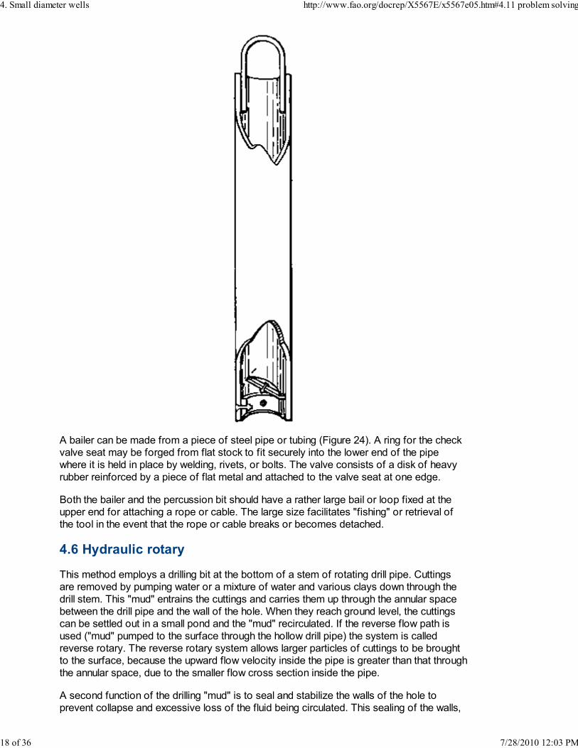
A bailer can be made from a piece of steel pipe or tubing (Figure 24). A ring for the check
valve seat may be forged from flat stock to fit securely into the lower end of the pipe
where it is held in place by welding, rivets, or bolts. The valve consists of a disk of heavy
rubber reinforced by a piece of flat metal and attached to the valve seat at one edge.
Both the bailer and the percussion bit should have a rather large bail or loop fixed at the
upper end for attaching a rope or cable. The large size facilitates "fishing" or retrieval of
the tool in the event that the rope or cable breaks or becomes detached.
4.6 Hydraulic rotary
This method employs a drilling bit at the bottom of a stem of rotating drill pipe. Cuttings
are removed by pumping water or a mixture of water and various clays down through the
drill stem. This "mud" entrains the cuttings and carries them up through the annular space
between the drill pipe and the wall of the hole. When they reach ground level, the cuttings
can be settled out in a small pond and the "mud" recirculated. If the reverse flow path is
used ("mud" pumped to the surface through the hollow drill pipe) the system is called
reverse rotary. The reverse rotary system allows larger particles of cuttings to be brought
to the surface, because the upward flow velocity inside the pipe is greater than that through
the annular space, due to the smaller flow cross section inside the pipe.
A second function of the drilling "mud" is to seal and stabilize the walls of the hole to
prevent collapse and excessive loss of the fluid being circulated. This sealing of the walls,
4. Small diameter wells http://www.fao.org/docrep/X5567E/x5567e05.htm#4.11 problem solving
18 of 36 7/28/2010 12:03 PM

however, can greatly reduce or prevent the inflow of water to the well unless proper steps
are taken to "develop" the well.
Two types of drilling bits are normally used: (i) a "fish tail" with two stationary blades for
use in soft materials and (ii) a rotary bit with three or more gear-like rollers which roll
around on hard material to crush and pulverize it.
Hydraulic rotary drilling is normally done with large engine-powered equipment. This
method is used almost exclusively in oil well drilling and is also commonly used in water
well drilling where wells are deep and much solid rock must be penetrated.
There are at least two exceptions to the large-scale equipment normally used for this
method. The first is a system based on a small, hand-held, vertical shaft, air-cooled
engine. A gear reduction unit integral with the engine has an output shaft which rotates at
approximately 60 rpm. Drill pipe of 1¼ inch nominal size is attached directly to this shaft. A
"tee" swivel near the top of the drill pipe allows water to be pumped down through it and
return to the surface via the annular space around it. A fish-tail bit is used for penetrating
soft materials. For hard materials a core drill is used. This is a tubular drill of hard, abrasive
material which cuts an annular groove and leaves a cylinder of uncut material inside the
drill. This uncut cylinder can be removed from the hole by wedging fine lead shot between
the core and the inside of the core drill and removing it from the hole along with the drill.
Alternatively, a core extractor with spring steel fingers for gripping the core may be used
for removal. A second small engine is generally needed to drive a pump for circulating
water.
A second system used in Bangladesh is completely hand operated, and is based on the
reverse rotary system. A string of drill pipe with a cutting bit at the bottom is rotated in the
hole by hand. A hand suction pump attached by means of a swivel to the top of the drill
pipe is used to raise water and cuttings. Water is supplied to the annular space around the
drill rod by a hand pump attached to two temporary driven wells.
Animal power has also been used to drive rotary drilling equipment.
4.7 Casing and screens
Casing serves two major functions : (i) to support the sides of the hole against collapse;
and (ii) to exclude contaminated surface water. The screen, which allows the water to enter
the well while preventing entry of the aquifer materials, may be a perforated section at the
lower end of the casing or may be a separate structure attached to the casing.
Depending on the drilling method used and the materials penetrated, the casing may be
sunk as an integral part of the drilling operation, as in the case of jetting; it may be placed
after the hole is completed; or it may be placed at some intermediate point, such as when
the water table is reached and the sides of the hole will collapse if not supported.
A number of different materials have been used successfully for well casing. These include
wrought iron pipe or tubing, tubing rolled from sheet metal, pipe made of plastic such as
polyvinylchloride (PVC) or glass reinforced plastic (GRP), asbestos-cement pipe, concrete
tile, clay tile, bamboo/coir casing (made of bamboo strips attached to steel hoops and
wrapped with coconut husk fibre cord and burlap), large diameter bamboo stems with the
node membranes removed and split palm trunks. The type of casing used will be
determined by (i) what materials are available locally; (ii) what skills are available locally;
(iii) the relative costs of labour and materials; (iv) the drilling method being employed; (v)
the nature of the geologic formation; and (vi) minimum acceptable life of the well.
A particularly noteworthy example of low cost, locally manufactured casing is the bamboo
4. Small diameter wells http://www.fao.org/docrep/X5567E/x5567e05.htm#4.11 problem solving
19 of 36 7/28/2010 12:03 PM

and coir casing developed in India (Figures 25, 26, 27 and 28). This casing consists of
longitudinal strips of split bamboo riveted to hoops spaced approximately 25 centimetres
apart. The assembly is then wrapped circumferentially with coir (coconut husk fibre) rope
until the entire length is covered. On those sections of the casing which penetrate the
aquifer the coir rope serves as a strainer or screen. On the remainder of the casing the
coir rope may be covered with burlap which is coated with asphalt. Sections of casing are
butted together and are attached by several longitudinal steel ties riveted to the end hoops
of the respective sections.
The life of these bamboo/coir casings is said to be two or three years. At the end of this
time it is necessary to bore a new well and to line it with a new casing. The use of
bamboo/coir casings is an excellent example of ingenuity and local labour, and skills being
used to save scarce capital and foreign exchange.
In Egypt date tree trunks are cut into one or two metre lengths, cleaned on the outside,
split, and hollowed out. During hand percussion drilling with a bailer and an under reaming
bit, the two halves are inserted into the hole and driven to depths of 100 to 200 metres.
Where galvanized sheet metal is readily available, casings can be made by rolling strips
into tubing with a longitudinal seam (Figures 29 and 30). In one case 1 m x 2 m sheets of
galvanized steel were split lengthwise into three equal strips. A single 90° bend was made
along one edge and a 90° bend plus a 180° bend was made along the other edge. These
were "rolled" by means of a 2 metre long wooden "V" block over which the sheet metal
was laid while downward force was being applied to a length of 2 inch diameter pipe
placed on top of it. By moving the sheet metal from side to side across the "V" block a
reasonably round contour could be obtained. The previously bent edges were hooked
together and bent over to form a seam. To accomplish the final rounding of the casing the
piece of 2 inch pipe was supported on blocks near its ends and used as an anvil. The
casing was slipped over the pipe and a mallet of wood or other relatively soft material was
used to do the finish forming.
Fig. 25 Coir casing. Split bamboo strips are spaced around steel rings and the
assembly is wrapped with coir cord.
Fig. 26 Coir casing. The coir wrapping serves as the well screen at the bottom end of
the casing.
Fig. 27 Coir casing. Casing which is above the aquifer is coated with asphalt and
burlap.
Fig. 28 Coir casing being lowered into bored hole.
Fig. 29 Fabricating sheet metal casing. (a) edges clamped between angle irons and
bent with mallet
4. Small diameter wells http://www.fao.org/docrep/X5567E/x5567e05.htm#4.11 problem solving
20 of 36 7/28/2010 12:03 PM

Fig. 29 Fabricating sheet metal casing. (b) rolling strip with pipe and wooden "V"
block
Fig. 29 Fabricating sheet metal casing. (c) hooking edges together to form seam
Fig. 29 Fabricating sheet metal casing. (d) crimping seam and rounding casing with
pipe anvil and mallet
4. Small diameter wells http://www.fao.org/docrep/X5567E/x5567e05.htm#4.11 problem solving
21 of 36 7/28/2010 12:03 PM

Fig. 30 Fabricating casing from galvanized sheet metal
The sheet metal casing is normally joined by slipping one end inside another and then
soldering the joint. Short longitudinal strips of sheet metal lapped across the joint and
soldered onto both lengths of casing can be used to further strengthen the joint, and are a
worthwhile practice. Ends can be made to fit together by selective assembly, by lightly
crimping one end, or by intentionally making the casing slightly tapered by varying the width
of the seam from end to end.
In the "California Stovepipe" method, two light sheet metal casings are used, one fitting
snugly inside the other. Joints on the inside casing come at the midpoint of the outer
casing sections and vice versa. The two layers are assembled and spot welded together
as they are sunk, thus creating a laminated casing which is relatively stiff and resistant to
buckling.
Asbestos-cement soil pipe and concrete or clay tile are frequently made with bell and
spigot joints to allow one end to slip loosely into the adjoining end for a short distance.
When using such pipe or tile as casing the bells point downward to minimize entry of loose
material through the loose joint into the well. The lengths may be lowered into the well
singly by means of a set of hooks attached to a cord. The hooks and cord fit inside the
casing and hold onto the lower end of the casing until it is in place and the hooks are
released by pulling on a second cord. Alternatively, if the string of casing is not too. heavy,
the joints may be wired together as they are assembled over the well and the casing
lowered from the top end. This technique would be limited to relatively shallow wells by the
weight of the string of casing.
Clay, concrete and asbestos cement tiles are relatively fragile and will break if such
operations as percussion drilling or bailing are attempted inside them. If such operations
are required for sinking the casing into the aquifer, it is necessary that the lowest section of
casing be of some more durable material such as steel tubing or pipe.
Polyvinylchloride (PVC) tubing or pipe is the plastic material most commonly used as well
casing. It is normally much less expensive than steel, lightweight, easy to cut and perforate
and insert. Sections are joined by means of painting the ends with a solvent to soften them
and then slipping them into a coupling where they fuse as the solvent evaporates.
4. Small diameter wells http://www.fao.org/docrep/X5567E/x5567e05.htm#4.11 problem solving
22 of 36 7/28/2010 12:03 PM

Perforation of casing to allow its use as a well screen can be accomplished by drilling or
by slitting with a hacksaw as was described in the section on well points.
A number of techniques have been used to help sink the casing as drilling progresses :
i. Driving: This technique was discussed earlier in connection with sinking well
points. It can be used normally only with heavy wrought iron casing using
special drive couplings which allow the casing ends to butt against each other,
thus protecting the threads from deformation. As pointed out earlier, driving is
accomplished by raising and dropping a weight which is guided either on the
inside or the outside of the casing and which strikes either on a special driving
cap screwed onto the end of the casing or on a clamp around the outside of
the pipe.
ii. Jacking: This technique (Figures 31 a and 32) makes use of timber anchors
buried alongside the well and jacks to maintain a downward force on the
casing as drilling continues.
iii. Weights (Figures 31b and 32) such as bags of soil or drums of water may
be piled on a support clamped around the pipe. Alternatively, a platform on
which the drillers' stand may be clamped to the casing (Figures 31 c and 33).
iv. Weights (Figure 31 d) on a lever which applies force to the casing.
Fig. 31 Sinking casing. (a) with help of jacks
Fig. 31 Sinking casing. (b) weighting with sacks of soil
4. Small diameter wells http://www.fao.org/docrep/X5567E/x5567e05.htm#4.11 problem solving
23 of 36 7/28/2010 12:03 PM
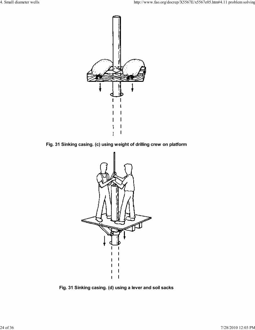
Fig. 31 Sinking casing. (c) using weight of drilling crew on platform
Fig. 31 Sinking casing. (d) using a lever and soil sacks
4. Small diameter wells http://www.fao.org/docrep/X5567E/x5567e05.htm#4.11 problem solving
24 of 36 7/28/2010 12:03 PM

Fig. 32 Sinking casing. Two methods are being used: (a) Workers near casing are
tightening nuts on large screws attached to timber anchors beneath the ground and
to top of casing. (b) Note large concrete weights clamped around casing just beneath
upper end. A second set of weights is located just above the ground surface.
Fig. 33 Sinking casing. Weight of drillers is being used to help sink the casing.
Workers on the ground are rotating the casing as drilling proceeds.
4.8 Methods for obtaining vertical reciprocating motion
A number of well drilling operations require a raising and dropping motion. These include
percussion drilling, bail down, hydraulic percussion and driving of casing. Large scale
percussion rigs obtain such a motion by cable with one fixed end running over a pulley at
the end of a pivoted arm reciprocated by a crank and connecting rod. The closest
analogue to this in man-powered equipment, Figures 34, 3 5 and 36, consists of a rope or
cable coming vertically out of the well, running over a pulley, then running parallel to the
ground at about shoulder height, and finally anchored to a tree or post. To obtain the
reciprocating motion a crew of 4-6 men line up facing the rope and alternately pull down
and release the rope in unison.
Another device successfully used consists of a lever pivoted over a horizontal axis, Figure
37, with the drilling tools attached to the shorter end and a crew of several men applying a
reciprocating motion to the longer end. Weights could be added to the longer end to
counterbalance partially the drilling tools if desired.
Fig. 34 Pulling on anchored horizontal rope to obtain reciprocating motion
4. Small diameter wells http://www.fao.org/docrep/X5567E/x5567e05.htm#4.11 problem solving
25 of 36 7/28/2010 12:03 PM

Fig. 35 Percussion drilling. Raising and dropping motion is obtained by pulling down
on rope and releasing. (A)
Fig. 35 Percussion drilling. Raising and dropping motion is obtained by pulling down
on rope and releasing. (B)
Fig. 36 Tripod mounted pulley used to obtain reciprocating motion for percussion
drilling and bailing
Fig. 37 Using lever to obtain reciprocating motion
There are a number of variations of the spring beam or spring pole system, Figures 38, 39
and 40. In Figure 38 the drilling line is attached to the end of a horizontal wooden cantilever
beam somewhat reminiscent of a diving board. The stiffness of the beam can be adjusted
either by changing the number of leaves in the spring or by changing the position of the
support nearest the end of the beam where the tools are attached. Depending on the
stiffness of the beam, the elasticity of the rope or other material attaching the tools to the
beam, the mass of the tools, and the nature of the materials being penetrated, the system
will have some natural frequency. That is, if the beam is bent and then released, the
system will oscillate at a constant number of cycles per minute with a continually
4. Small diameter wells http://www.fao.org/docrep/X5567E/x5567e05.htm#4.11 problem solving
26 of 36 7/28/2010 12:03 PM

decreasing length of stroke until the motion is completely damped out by friction in the
system. If on each downstroke a downward pull is applied, the system can be made to
oscillate indefinitely with a minimum work input. In practice, a work crew stands around the
line attached to the spring beam and supplies a downward force at appropriate intervals to
keep the system oscillating. Alternatively, a separate rope for each can be attached to the
beam. Each worker places his foot in a loop or stirrup and supplies the necessary motion
with his leg and foot. This method is sometimes referred to as "kicking down a well". As
the mass of tools, depth of hole and material penetrated change, the natural frequency of
the system changes. This can be compensated for by adjusting the stiffness of the beam
either by changing the number of leaves or the unsupported length. A greater tool mass will
decrease the number of oscillations per minute while a greater beam stiffness will increase
them.
Slightly less sophisticated, but widely used in North America during the first half of the 19th
century is the spring pole (Figure 39). This is made from a tree 8-10 m long with a diameter
tapering from approximately 20 cm at one end to 10 cm at the other. The large end is
anchored to the ground possibly by piling rocks or logs on it. It is supported by a fulcrum at
approximately one-third of the length from the lower end. The upper end might be at a
height of 2.5-3.0 m. Stirrup ropes could be attached to the upper end for oscillating the
pole.
In both the case of the spring beam and the spring pole, an overhead pulley is necessary
for pulling the tools out of the hole and for bailing. This pulley would normally be supported
on a separate structure such as a tripod.
Figure 40 shows a Chinese well drilling device which makes use of a large bow to obtain
the oscillating motion. This general type of device goes back at least 2 600 years and has
been credited with drilling to depths of 1 000 m. Such wells were used to obtain brine from
which salt was made in the interior of China. The drill line is made of sections of split
bamboo which are spliced together by cutting interlocking notches where ends overlap and
banding the splice together with steel or hemp. Good bamboo has about the same tensile
strength per unit of weight as mild steel. It is obviously not as flexible as rope or cable,
however, and so the large diameter reel shown is used to wind up the bamboo drill line.
Some dimensions given for the device pictured in Figure 39 are:
Length of Bow 12 - 15 m
Diameter of Bow 20 - 25 cm
Diameter of Steel Cable for Bow String 15 - 16 mm
Diameter of Reel 4 m (approximately)
A rotating drum or "cathead" driven by any convenient power source is frequently used in
well drilling operations (Figure 41). If a rope is wrapped loosely around the rotating drum, it
will remain stationary while the drum rotates. When one end of the rope is pulled taut,
however, friction will cause the rope to move with the drum surface and the rope and drum
combination can be used as a windlass. By alternately pulling the rope taut and letting it go
slack, it is possible to raise and drop a weight such as a percussion bit, a set of hydraulic
percussion tools, or a bailing bucket. By continually keeping the end of the rope taut as it
feeds off the drum, the system can also be used to pull the tools out of the well.
Fig. 38 Spring board for obtaining reciprocating motion
4. Small diameter wells http://www.fao.org/docrep/X5567E/x5567e05.htm#4.11 problem solving
27 of 36 7/28/2010 12:03 PM

Fig. 39 Spring pole for obtaining reciprocating motion..
Fig. 40 Traditional Chinese drilling equipment. (a) rig with bow for obtaining
reciprocating motion and reel for bamboo drill line
4. Small diameter wells http://www.fao.org/docrep/X5567E/x5567e05.htm#4.11 problem solving
28 of 36 7/28/2010 12:03 PM

Fig. 40 Traditional Chinese drilling equipment. (b) splice in split bamboo drill line
Fig. 40 Traditional Chinese drilling equipment. (c) drilling tools
4. Small diameter wells http://www.fao.org/docrep/X5567E/x5567e05.htm#4.11 problem solving
29 of 36 7/28/2010 12:03 PM

Fig. 41 Rotating drum or "cathead" to obtain reciprocating motion or for use as a
winch
4.9 Rope
Drilling systems such as augering, jetting and hydraulic percussion make use of a string of
pipe or tubing to connect the actual drilling tools with the power input at or above ground
level. Whenever tools must be brought up to the ground surface it is necessary to
disconnect the lengths of pipe one by one and to set them aside. Returning the tools to the
bottom of the hole requires a reversal of this procedure. As the hole becomes deeper, this
process becomes more time consuming and progress is thus slowed. Early percussion
4. Small diameter wells http://www.fao.org/docrep/X5567E/x5567e05.htm#4.11 problem solving
30 of 36 7/28/2010 12:03 PM

drilling was carried out with rigid drill stems made of wooden or steel sections coupled
together. These likewise had to be coupled and uncoupled every time tools were put into
or taken out of the hole. In present day percussion drilling and bailing, on the other hand,
the tools are normally connected flexibly to the power input by a rope or cable. This means
that the tools may be quickly removed from or returned to the hole merely by pulling up or
letting out the rope without any disconnecting or connecting.
Both manilla rope of 25-40 mm (1-1½ inch) diameter and steel rope or cable of
approximately 10 mm (3/8 inch) diameter have been used successfully in self-help well
drilling operations. To extend the life of the wire or manilla rope, the maximum practical
pulley diameter should be used. Locally made ropes with short or coarse fibres, such as
coir (coconut husk fibre) may be undependable and short-lived and cause delays and
losses far in excess of the money saved by their use..
The drill lines of split bamboo successfully used in Asia for over 25 centuries were
mentioned earlier.
4.10 Well development and finishing
The term well development refers to the process of removing the finer particles from the
aquifer immediately around the well screen in order to make the aquifer more permeable
and thus to decrease the resistance to flow of water into the well. This means that for a
given rate of pumping the drawdown of the well and consequently the pumping height will
be decreased. In order to develop a well, it is important that the openings in the well screen
be chosen of the proper size. This necessitates collecting material taken from the aquifer
during the process of drilling. One rule-of-thumb states that the openings should be of such
a size that the smallest 2/3 of the aquifer particles will pass through them.
Development is accomplished by causing the water to alternately flow into and out of the
well. During inflow some small particles will be carried into the well through the screen, but
other small particles will bridge between particles too large to pass through the screen. The
reversal of flow will dislodge such particles and give them the opportunity to pass through
the screen during the next period of inflow. The fine material entering the well is ultimately
removed with the water. Removal of the fine material during development, in addition to
increasing the capacity of the well, saves the pump which is later installed from abrasion.
Bailing the well is probably the simplest method of development. Each time the bailer is
raised and dropped water surges into and out of the well. Fine material entering the well is
trapped inside the bailer and removed from the well. The amount of fine material in the
bailer indicates how far the process of development has proceeded. A special type of
bailer known as a sand pump has a piston inside it. This piston is attached to the bailer line
in such a way that it travels upward inside the bailer as the line goes from slack to taut. The
motion of this piston has a strong surging effect on the well and helps to draw sand into the
bailer.
A surge block, which acts as a piston or plunger inside the casing, can be attached to a
string of pipe and made to travel up and down for the purpose of development. A surge
block may consist of two or more wooden disks fastened together with rubber between
them which makes contact with the inside of the casing.
Wells may also be developed by pumping water out at a high rate to create a large
drawdown. Pumping is suddenly stopped and a large quantity of water which has been
accumulated is allowed to run down into the well to reverse the flow through the aquifer
around the screen. Compressed air may also be used to surge a well during development
operations.
4. Small diameter wells http://www.fao.org/docrep/X5567E/x5567e05.htm#4.11 problem solving
31 of 36 7/28/2010 12:03 PM

If an aquifer consists of fine particles without much variation in size, it may not be possible
to increase the permeability around the screen adequately by the development techniques
described above. In this case the capacity of the well can be increased by gravel packing,
i.e. by introducing material around the screen which has a particle size greater than that
found in the aquifer. Use of a gravel pack allows larger screen openings to be used, and
hence gives greater percentage of inflow area. It also surrounds the screen with a layer of
material of higher permeability than the aquifer itself.
One way to introduce the gravel is initially to sink a temporary casing of a diameter greater
than that of the final casing and screen. The final casing and screen are lowered inside the
temporary casing and are held concentric by guides while the gravel is introduced into the
annular space between the casings. The temporary casing can then be jacked out of the
hole. Another method is to drill the hole somewhat larger than the casing down to the water
table. The casing is then lowered and the annular space between the casing and the hole is
filled with gravel. As sinking of the casing into the aquifer proceeds, some of the gravel
descends with the casing. During development, more of the gravel descends to occupy the
volume left by the sand passing through the screen into the well. Gravel may also be
introduced around the screen through several small holes drilled for this purpose around a.
small circle concentric with the well.
The size and gradation of the gravel used should be such that very little of the material of
the surrounding aquifer can flow into the voids between the gravel particles. If this
happens, the permeability of the gravel pack may be greatly reduced. The screen opening
size is selected as large as possible without allowing any of the gravel pack material to
enter the well.
After the well has been developed it is usually desirable to fill in and seal the annular space
between the outside of the casing and the hole. This operation known as grouting is carried
out to prevent any dirty surface water from flowing directly into the well and to give the
upper end of the casing firm support. A mixture of portland cement and water mixed to a
fairly liquid concistency is the most commonly used grouting material. A clay-water slurry is
sometimes also used at greater depths where changes in moisture will not cause shrinking
and swelling of the clay.
Where the use of pumping equipment for placing the grout is not practical, it must be
flowed into place by gravity. The annular space between casing and hole should probably
not be less than 5 cm (2 inch). A long, slender rod can also be used to make sure the grout
flows into all voids. The grout should extend from the surface to a depth of at least 6 m (20
feet) to ensure an adequate sanitary seal between casing and drilled hole.
4.11 Problem solving
No endeavour is without problems, but those encountered in the drilling of small diameter
wells may seem more difficult since they generally occur in a location where they cannot be
seen. Consequently, a high degree of "feel", deduction, reasoning and ingenuity must be
developed to diagnose and to overcome problems. Well drillers have two cardinal rules
concerning problems :
(1) Prevent problems before they occur rather than trying to remedy them
after they occur. This requires a great deal of alertness to sounds, feel,
physical condition of tools and cuttings and continually trying to anticipate
what things could possibly go wrong.
(2) In trying to remedy a problem, do not do anything quickly or ill-considered
which could make the problem more difficult or impossible to solve.
4. Small diameter wells http://www.fao.org/docrep/X5567E/x5567e05.htm#4.11 problem solving
32 of 36 7/28/2010 12:03 PM

In drilling wells, particularly with labour-intensive systems, at least three types of problems
arise:
a. Small tools dropping into the hole. Any tool small enough to fit into the hole
and regularly used around the hole will sooner or later get dropped in. To
prevent this, all such tools should be tied to some stationary object with strong
cord. Long slender objects, such as auger extensions which are regularly
coupled and uncoupled, should have a safety device, such as a piece of rod
slipped through them to prevent them from sliding down the hole if dropped
accidentally. "Fishing" techniques for removal of objects from the hole are
discussed later.
b. Tools stuck in the hole. While some cases of stuck tools are probably
inevitable, proper design and maintenance can minimize the number of cases.
The cutting edges of tools should be made and maintained so that they cut a
hole large enough to allow clearance around the remainder of the equipment.
Tools should be designed with reasonably smooth transitions in cross-section
so that sharp shoulders do not exist which could become hooked under an
irregularity in the hole or above which excavated particles could be wedged.
When tools do become wedged in the hole, it is usually necessary to make
use of some force-multiplying device such as a chain hoist or automotive
jacks to pull them free. Since the force required to free the tool can often be
considerable (even if only a small piece of gravel is wedged between the tool
and the casing), equipment should be built to withstand several tons of pull. If
there is concern for the rope, cable or a string of pipe breaking during hard
pulling, it is usually possible to hook directly onto the stuck tool with a properly
designed hook at the end of another stronger rope, cable or string of pipe.
Pulling can then proceed on the latter or on both attachments. The necessity
of hooking onto the tops of tools should be kept in mind when they are
designed. For example, bailers and percussion bits should be made with large,
easy-to-hook bails.
Commercially made percussion tools include a set of "jars". This is a heavy
close fitting pair of links built into the drill system. Since the links can slide
within each other, the part of the drill stem above the jars can be pulled up a
short distance before the drilling bit leaves the bottom of the hole. This small
relative motion and the mass of the upper drill stem and line can be used to
drive a stuck drill bit upward to free it. The impact of the jars exerts a greater
force than can normally be obtained by a steady pull. If the drill bit is stuck
above the bottom of the hole, the jars can also be used to drive downward.
The forerunner of jars was two or three heavy chain links connecting the upper
and lower part of the drill stem. These, however, take a heavy beating on both
the upstroke and the down-stroke and are relatively short-lived.
c. Tools which become detached in the hole. The occurrence of this problem
can be minimized by continually checking the condition of the tools and
fasteners. However, when a detached or dropped tool must be removed from
the hole, the process is referred to as "fishing". Frequently special tools must
be fabricated to accomplish this task. This may require both considerable
ingenuity and a good deal of trial and error. An impression block may be
valuable in designing fishing tools. This is a shallow cylindrical container of a
diameter which just fits in the hole, with an open bottom and the top attachable
to a string of pipe or a bailer. The container is filled with a substance such as
soap, wax or grease hard enough to hold its shape, but soft enough to take an
impression. It is carefully lowered onto the object to be fished, so that the
impression left on the block gives information on the shape, location and
4. Small diameter wells http://www.fao.org/docrep/X5567E/x5567e05.htm#4.11 problem solving
33 of 36 7/28/2010 12:03 PM

orientation of the object which is useful in choosing the tools and strategy to
be used in fishing. An impression block can be made of a thick wooden disk
with a strip of sheet metal nailed around the outer edge. The wooden block
can be studded with nails to anchor the impression material.
Some commonly used fishing tools are shown in Figure 42. Other tools must
be devised to suit a given problem.
Fig. 42 Fishing tools. (a) for retrieving lengths of pipe
Fig. 42 Fishing tools. (b) sheet metal cylinder with teeth which bend together to close
bottom for picking up small objects
4. Small diameter wells http://www.fao.org/docrep/X5567E/x5567e05.htm#4.11 problem solving
34 of 36 7/28/2010 12:03 PM

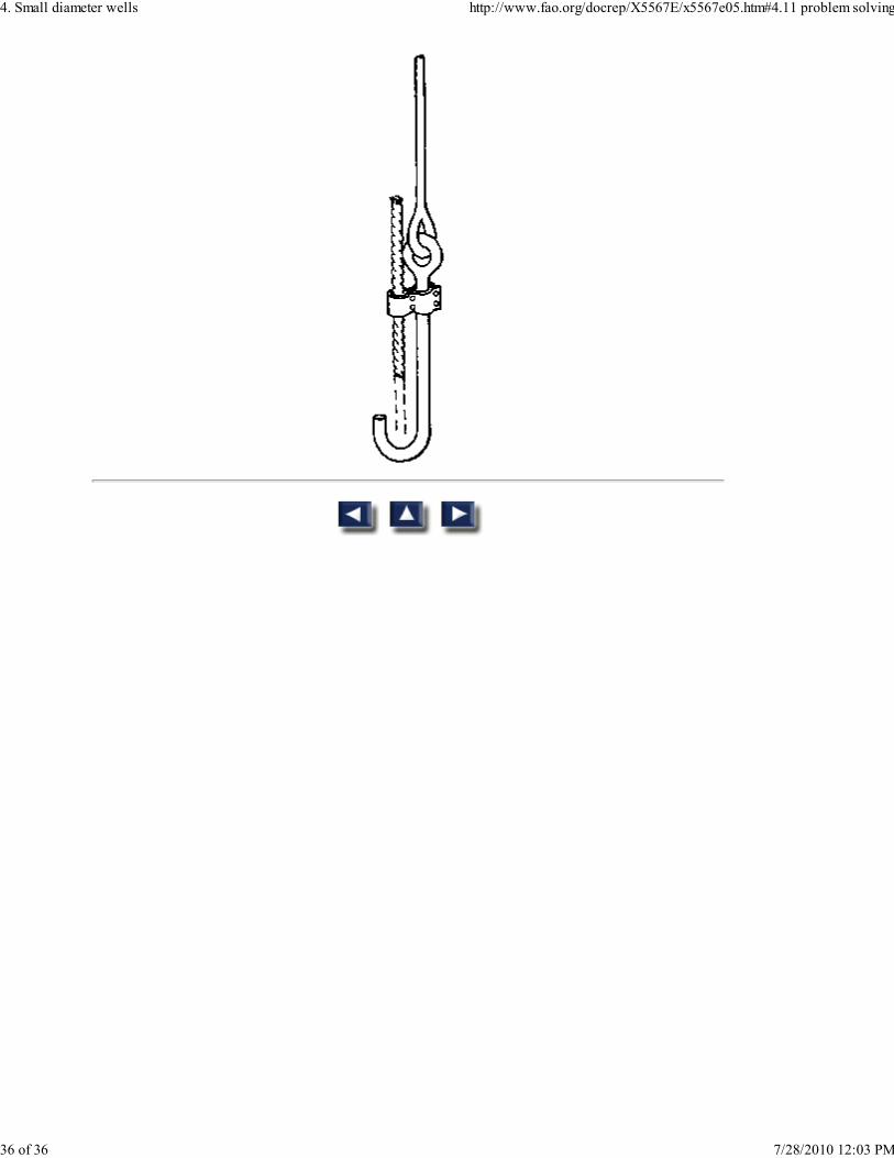
Fig. 42 Fishing tools. (c) spear for retrieval of broken rope or cable with latch for
picking up bits or bailers
Fig. 42 Fishing tools. (d) hook with guide for attaching supplemental line to stuck tool
4. Small diameter wells http://www.fao.org/docrep/X5567E/x5567e05.htm#4.11 problem solving
35 of 36 7/28/2010 12:03 PM
4. Small diameter wells http://www.fao.org/docrep/X5567E/x5567e05.htm#4.11 problem solving
36 of 36 7/28/2010 12:03 PM