4. experimental systems - lle.rochester.edu
TRANSCRIPT

July 2014 Chapter 4: Experimental Systems Page 4.1
4.1 Scope
Experimental systems include the facilities necessary to support the target and diagnostics, and to provide the environment for the experiment. These systems are designed to balance the physics requirements of the mission with the need to minimize intershot turnaround times to fulfill the mission while delivering the best cycle times possible.
On OMEGA, these facilities are located in the Target Bay, LaCave (the rooms directly below the Target Bay), a pump house located adjacent to the Target Bay, and in a number of support laboratories within LLE.
On OMEGA EP, these facilities are located in the OMEGA EP Target Area at the north end of the OMEGA EP Laser Bay, the Diagnostic Bays (Room 5000, directly below the OMEGA EP Target Area), and the Room 6106-8 suite to the east of the OMEGA EP Target Area.
The OMEGA Target Bay and the OMEGA EP Laser Bay are Class-1000 clean room areas. All materials entering these areas must conform to clean room requirements.
All equipment deployed in these areas must complete an approval process outlined in LLE INST 7700.
4.2 Vacuum Environment
Experiments on OMEGA and OMEGA EP are conducted in high-vacuum (5 × 10⁻⁷ to 8 # 10–5 Torr) environments.
A shared network of vacuum sources is installed in the Omega Laser Facility to provide the necessary environment for experiments. To maintain necessary cleanliness and vibration levels, all mechanical pumps and cryopump compressors are located in a pump house external to and mechanically isolated from the OMEGA and OMEGA EP bays. Installation of mechanical pumps or cryopump compressors is prohibited inside the OMEGA Target Bay and OMEGA EP Target Area.
4.2.1 Target Chambers
Physics experiments on OMEGA and OMEGA EP are conducted within the respective Target Chamber (TC) for each system. Both OMEGA and OMEGA EP TC’s are 3.3-m-diam spheres with ~8-cm walls of type-5083 aluminum. The OMEGA TC is fitted with 92 ports, while the OMEGA EP TC has 91 ports.
4. Experimental Systems

July 2014Page 4.2 Omega Facility Users’ Guide
Locations in the TC’s are described using spherical coordinates shown in Fig. 4.1. The system origin is the target chamber center (TCC). The radius r is generally in units of microns or millimeters, and declination (i) and azimuthal (z) angles are in degrees.
Diagnostics, beam-transport lenses, short-pulse beam-transport tubes, target support and viewing systems, and vacuum systems are mounted to these ports, often through adapters that make it possible for several devices to share the same port. Current port assignment tables may be found on the Omega PI Portal website.
Figure 4.1Target Chamber coordinate system (OMEGA EP TC shown).
G7118J1
0°
45°
90°
135°
180°
Declination angle (i)(elevation view)
0°
315°
270°
225°
180°
45°
90°
135°
Azimuthal angle (z)(plan view)
Up North
4.2.2 Vacuum Systems
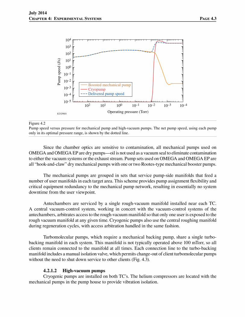
Both TC’s and most antechambers in OMEGA and OMEGA EP experimental areas use a combination of mechanical vacuum pumps and high-vacuum pumps to achieve operating vacuum levels below 8 # 10–5 Torr. As shown in Fig. 4.2, the efficiency of each of these pump types is high over only a limited pressure range and drops to a negligible pump speed at other pressure ranges. Mechanical pumps are typically used from atmospheric pressure (760 Torr) to a “crossover” pressure (shown below at around 10 mTorr), which optimally exploits the pump speed versus pressure characteristics of each pump stage.
4.2.1.1 Rough vacuum systemsTC’s and their antechambers are serviced by mechanical pumps that are located in a separate
building whose foundation does not connect with the OMEGA and OMEGA EP bays. This provides vibration isolation between the optical systems and these pieces of large rotating equipment.
July 2014 Chapter 4: Experimental Systems Page 4.3
Since the chamber optics are sensitive to contamination, all mechanical pumps used on OMEGA and OMEGA EP are dry pumps—oil is not used as a vacuum seal to eliminate contamination to either the vacuum systems or the exhaust stream. Pump sets used on OMEGA and OMEGA EP are all “hook-and-claw” dry mechanical pumps with one or two Rootes-type mechanical booster pumps.
The mechanical pumps are grouped in sets that service pump-side manifolds that feed a number of user manifolds in each target area. This scheme provides pump assignment flexibility and critical equipment redundancy to the mechanical pump network, resulting in essentially no system downtime from the user viewpoint.
Antechambers are serviced by a single rough-vacuum manifold installed near each TC. A central vacuum-control system, working in concert with the vacuum-control systems of the antechambers, arbitrates access to the rough-vacuum manifold so that only one user is exposed to the rough vacuum manifold at any given time. Cryogenic pumps also use the central roughing manifold during regeneration cycles, with access arbitration handled in the same fashion.
Turbomolecular pumps, which require a mechanical backing pump, share a single turbo-backing manifold in each system. This manifold is not typically operated above 100 mTorr, so all clients remain connected to the manifold at all times. Each connection line to the turbo-backing manifold includes a manual isolation valve, which permits change-out of client turbomolecular pumps without the need to shut down service to other clients (Fig. 4.3).
4.2.1.2 High-vacuum pumpsCryogenic pumps are installed on both TC’s. The helium compressors are located with the
mechanical pumps in the pump house to provide vibration isolation.
E23298J1
104
103
102
102 101 100
Operating pressure (Torr)
10–1 10–2 10–3 10–4
101
100
10–1
10–2
10–3
10–4
10–5
Pum
p sp
eed
(I/s
)
Boosted mechanical pumpCryopumpDelivered pump speed
Figure 4.2Pump speed versus pressure for mechanical pump and high-vacuum pumps. The net pump speed, using each pump only in its optimal pressure range, is shown by the dotted line.

July 2014Page 4.4 Omega Facility Users’ Guide
Most antechambers use small, directly mounted turbomolecular pumps as their high-vacuum stage. These share common backing manifolds near the TC, which are serviced by the mechanical pumps located in the pump house. Turbomolecular pumps typically operate continuously, but are seldom opened directly to the TC for reasons of contamination control.
4.2.1.3 Emissions controlBecause of the nature of many of the experiments conducted on OMEGA, exhaust streams
from the OMEGA TC and antechamber rough-vacuum pump is filtered by the Target Chamber Tritium Recovery System (TC-TRS) to capture tritium that may be present in the exhaust stream.
4.3 Target Handling Systems
Targets delivered to OMEGA and OMEGA EP are mounted on lightweight stalks that connect to our target positioners using either a standard pin or, in certain cases, an LLNL Nova-type magnetic base. Stalks are usually 2.75 in. from pin shoulder to target, with other dimensions as shown in LLE drawing D-TC-C-042 (Fig. 4.4). Targets are usually positioned within a 15-mm radius of TCC. Multiple targets may be used on a single shot. Target alignment is managed by procedures written specifically for each target type and issued for each shot day. The Experimental Operations Group writes and publishes these procedures in partnership with the Principal Investigator (PI) for the experiment.
When targets are delivered to the facility in pressurized cells, the cell pressure is read out and logged, along with a time stamp, when the cell is opened to load the target into the TC. This measurement is available to the PI.
E23299J1
Figure 4.3Typical mechanical pump with booster and pump-side vacuum manifold.

July 2014 Chapter 4: Experimental Systems Page 4.5
4.3.1 Target Positioning Systems
The stalk-mounted targets are supported on a target positioner. Two classes of target positioners are used at the Omega Laser Facility. Both types of target positioners provide four axes of control—three translation axes and rotation about the stalk axis (Fig. 4.5).
4.3.1.1 Fixed TPS (TPS 2, TPS 7, TPS 83)The standard Target Positioning System (TPS) is an airlock equipped, four-axis unit that is
mounted directly to the TC. One unit is available on OMEGA (port H2) and two on OMEGA EP (ports 7 and 83). These are controlled from the Experimental System Operator (ESO) station in each control room.
E23300J1
0.57±0.021.93This applies to the endof the 1.70-in. �bers
Three boron �bers, 142-nm outer diamwith 30-nm-diam carbon core
(lengths: 2.00 in., 1.70 in., and 1.70 in.) 70-nm SiC �ber(silicon carbide)
17-nm-diam SiC �ber
Target (deviation from pin axis
to be less than 0.030)
0.040±0.10This applies to the 17-nm-diam �ber
2.75
Figure 4.4Typical target assembly (from D-TC-C-042).
E23301J1
y
x
z
TCC
~
Figure 4.5Target-alignment control axes.

July 2014Page 4.6 Omega Facility Users’ Guide
TPS’s accept only the LLE pin-equipped target stalks. Target-pressure readout is not available on the TPS. A soft-rough option, used primarily with aerogel-filled targets that cannot tolerate rapid decompression, is available, but increases the required cycle time.
The TPS is the primary, and preferred, target positioner for both systems, providing high-accuracy positioning with minimum cycle time.
4.3.1.2 TIM TPS (TTP)Two ten-inch manipulator (TIM)–based target positioners are available on OMEGA and two
on OMEGA EP. These convert a TIM into a target positioner by adding an adapter that includes a stalk-rotation stage. Translation is done using the TIM steering stages.
If needed by the experiment, the OMEGA TTP supports the use of a standard pressure transducer to monitor the target gas pressure. The operating crew logs this data. Note that the length of the tube that connects the target to the pressure transducer is a critical length. It must be 24.0!0.5 in. in length as shown in LLE drawing D-EA-G-354. This gas-handling capability is not currently available on OMEGA EP (Fig. 4.6).
The TTP also can be configured to use the LLNL Nova magnetic target mount. This permits the use of a higher-mass target assembly than is practical with the TPS. These mounts are required when the pressure-transducer configuration is used (Fig. 4.7).
E23302J1
C
C
Detail A
6 5
Detail B
Figure 4.6Gas-filled target configuration from LLE drawing D-EA-G-354 showing critical dimension of fill hose.

July 2014 Chapter 4: Experimental Systems Page 4.7
4.3.2 Target Viewing System
The target position is determined using the Target Viewing System (TVS) on both OMEGA and OMEGA EP. TVS is a shadowgraph system—only the silhouette of the target is observed.
The TVS on each system has two optical axes, each mounted nearly orthogonal to each other to provide 3-D position-locating capability.
Each axis has a pulsed illuminator system that backlights the target region, and an optical relay system that images the target region onto a number of camera channels. Different camera channels have differing magnifications or time resolution.
A database-driven reticle generator is used to overlay reticles on the images that correspond to specific spherical coordinate locations. This supports precise positioning of targets. Both systems have a reticle-management system that supports multiple reticles as well as unique reticle packages for specific targets.
TVS operating specifications are shown in Tables 4.1 and 4.2.
E23303J1
Pressure transducerbarrel adapter
Gas manifold/pressuretransducer mount
Gas-�lled targethold downs
LLE pin-styletarget and mount
Gas-�lled targetand mount
Three-position mountfor rotation stage
Figure 4.7TIM TPS (TTP).

July 2014Page 4.8 Omega Facility Users’ Guide
Table 4.2: OMEGA EP Target Viewing System.
View Port i z
x axis 75 120° 270°
y axis 68 111° 0°
Angle between views 79.68°
Camera name Focus control Nominal resolution (nm/pixel)
Field of view (nm)
CCD array size (pixels)
Frame rate (fps)
Narrow view (TCS)
No 5 5 # 5 1000 # 1000 30
Wide view (TVS)
Yes 15 30 # 30 2048 # 2048 12
Table 4.1: OMEGA Target Viewing System.
View Port i z
x axis P5 63.435° 270°
y axis H6A 77.28° 19.96°
Angle between views 101.50°
Camera name Focus control Nominal resolution (nm/pixel)
Field of view (nm)
CCD array size (pixels)
Frame rate (fps)
Narrow view (TCS)
No 5 10 # 10 2048 # 2048 $5
Wide view (TVS)
Yes 24 50 # 50 2048 # 2048 $5
Smart camera (TED)
No 78 50 # 37.5 640 # 480 $500
HS video (TVS)
Yes 10 10 # 10 1016 # 1016 100 to 2000

July 2014 Chapter 4: Experimental Systems Page 4.9
4.4 Diagnostic Support Facilities
4.4.1 TC Port-Mounting Flanges
Diagnostics may be mounted directly onto a TC flange or a sub-port on a sub-divided port. These diagnostics are referred to as “fixed” diagnostics. Port assignment for a fixed diagnostic tends to be long term. A listing of current port assignments for each TC can be found on the Omega PI Portal website.
All ports flanges, including actual TC ports and sub-ports, are of proprietary design and are O-ring sealed. Bores are 2, 4, 6, 8, 12, 18, and 24 in. Ports and sub-ports are always aligned perpendicular to a TC radial line.
4.4.2 Ten-Inch Manipulators
The ten-inch manipulator (TIM) is a diagnostic mounting system that supports an instrument in a cradle. The TIM can insert the diagnostic into the TC vacuum space and precisely position it in three axes (Fig. 4.8).
G7127J1
Diagnosticpayload
Boat
Antechamber
TCC
Steeringgimbal
Steering controlpylon and stages
Targetchamberisolation
valve
Figure 4.8Typical TIM.

July 2014Page 4.10 Omega Facility Users’ Guide
The diagnostic is loaded into the cradle, called a “boat,” inside the top-loading antechamber. An umbilical is available to continuously connect the diagnostic to external controllers, timing triggers, timing monitor scopes, and coolant supply/return. A TIM payload must not exceed 100 lbs. The envelope of maximum payload dimension is shown in Fig. 4.9.
The TIM attaches to the TC via a steering gimbal, which facilitates steering the payload laterally and vertically. Positioning along the TC radial direction is accomplished by moving the boat with the transport drive.
Each TIM has a vacuum system with a turbomolecular high-vacuum pump, and is serviced by the house-roughing and backing manifolds. The vacuum and positioning systems on each TIM have a single control system that integrates into the main vacuum control stations in each control room.
G4635J1
Linear dimensions in inches
16˚
58.4
Side view
R4.50max.
R4.19max.
4.943.20
0.56 7.13
0.50
1.00
8.250±0.010
Front view
Figure 4.9Maximum dimensions for a TIM payload.

July 2014 Chapter 4: Experimental Systems Page 4.11
Six TIM’s are installed on OMEGA. Five TIM’s are installed on OMEGA EP. Their locations are shown in the port assignment tables that are viewable on the Omega PI Portal website.
4.4.3 Diagnostic Timing
Target diagnostics are usually triggered from the OMEGA or OMEGA EP Hardware Timing System (HTS). The HTS delivers TTL-level trigger pulses that are synchronized to the OMEGA or OMEGA EP Laser System. The HTS supports timing adjustments in increments of 100 ps. The actual timing resolution is then subject to the timing jitter of the diagnostic.
On TIM–based diagnostics, a calibrated timing-monitor system is available. This system records the monitor output signal from the diagnostic (which describes the acquisition window of the diagnostic) on an oscilloscope, which includes a pulse that is calibrated to the laser arrival at the target in a known frame of reference (Fig. 4.10).
Fiducial (IR)
Fiducial (IR)
1 2 3 4
Fiducial table(north EMS)
PLASFASP’s
TCC
Beam energy in IR, UV, green
Pulse shape and beam timing
HTS
Amp
HTS
HED’s
P510’s
Regen ampli�ers(26-ns cycles)
A, B, Campli�ers
Shaping
Dtregen
t0
DtCE
DtXR
DtRT
DtPLAS
Dt0
Fiducial (green)
Fiducial (green)
Fiducial (UV)
Fiducial (UV)
G10101J1
ShapingPulsegeneration
FCC’s D, E, F ampli�ers
HTS
Diagnostic
tdiagnostic DtCI
Diode
Figure 4.10Schematic of typical diagnostic and laser timing.
July 2014Page 4.12 Omega Facility Users’ Guide
Operators can test fire diagnostics without expending a laser shot or target, record the monitor pulse and the reference pulse, and precisely adjust timing. An extensive database is maintained to enable the operators to trigger the diagnostics at the acquisition time (relative to T-0, the nominal laser arrival time on target) that the PI requests. This “housekeeping” data is collected and is available online after the shot.
A video that illustrates our standard diagnostic timing scheme is available in LLE document M-TM-M-019 (“XRFC Timing Concepts”).
4.4.4 Diagnostic Alignment
Diagnostic-alignment strategies vary according to the alignment tolerances of the particular diagnostic. Most TIM–based diagnostics, however, use a similar alignment scheme in which a pointer, which terminates at the aiming point of the diagnostic, is installed on the front of the diagnostic. The diagnostic is then aligned by maneuvering the TIM until the pointer is aligned to a reticle in the TVS that corresponds to the desired pointing location for the diagnostic for a particular shot configuration. The TIM steering coordinates, along with a reference to the diagnostic and shot configuration, are recorded in the database. The TIM is then retracted, the pointer is removed, and the diagnostic is configured for the shot. The TIM is driven to the recorded coordinates for the shot. Alignment resolution is limited primarily by the positioning repeatability of the TIM/diagnostic. Typically, repeatability in position of <50 nm is achievable. Higher-resolution positioning may require alternate methods.
4.4.5 Data Processing
Both OMEGA and OMEGA EP have facilities and staff to process film and image plate (IP) on site in a timely manner. Each facility has a processing laboratory, located near each target area.
Film data is processed in JOBO ATL processors after each shot. The processed film is marked, cut, packaged, and delivered to the PI. The PI is welcome to visit the processing laboratory during the shot day to assess the film data. LLE does not generally provide any data-analysis services nor does it store user film data. However, digitizing film data can be made available to the user upon special request. Kodak T-Max, BioMax, and DEF are among the film types supported. Some film types can be supplied by LLE, or accommodation for user-supplied film can be made.
IP data is scanned following each shot using GE Typhoon 7000FLA or Fuji 7000FLA IP scanners, located in the processing laboratories. Output is available online shortly after the shot in either HDF format or the native format of the scanner. IP is generally supplied by LLE.
4.4.6 Radiation Control Considerations
4.4.6.1 Nuclear activation OMEGA and OMEGA EP can generate conditions that result in significant nuclear activation
of materials inside the bay shield walls, and in the TC’s in particular. Under conditions on OMEGA

July 2014 Chapter 4: Experimental Systems Page 4.13
or OMEGA EP where significant levels of nuclear activation are expected, diagnostics are surveyed for gamma activity after a shot. This equipment must be certified by LLE to be less than 0.1 mrem/h on contact prior to release from the facility or access by users.
For users who have access to the OMEGA Target Bay and OMEGA EP Bay areas, access is not prohibited when the measured activity in those areas exceeds 5 mrem/h.
4.4.6.2 Tritium contaminationDiagnostic instruments that are installed inside the OMEGA TC vacuum space are exposed to
tritium contamination in addition to any ionizing radiation that may be generated by the experiment. Contamination levels within the OMEGA TC at or above 106 dpm/100cm2 for 3H are common.
Equipment exposed to the OMEGA TC vacuum space is quarantined and surveyed for tritium upon removal from that space. This equipment is not released from the facility or accessible by users unless that level is below the 1000-dpm/100cm2 3H free release limit (3H FRL). Items whose contamination levels exceed the 3H FRL must be decontaminated by LLE personnel prior to access by users or release from the facility.
4.4.7 Beryllium Contamination Considerations
The use of beryllium in targets and diagnostics within the OMEGA TC and the OMEGA EP TC is permitted. As a result, consideration of equipment contamination within the TC vacuum spaces is important.
Equipment that has been within the TC vacuum spaces of OMEGA or OMEGA EP may be contaminated with beryllium particulate. Equipment is wiped down after removal from either TC; however, LLE does not have a fast turnaround beryllium assay capability. Obtaining survey results may take several weeks, so surveying equipment prior to release is not practical. Historical surveys indicate that wiped-down equipment is generally below the 0.2-ng/100m2 beryllium acceptable surface-contamination limit (Be ASCL).
Work areas, including those adjacent to the TC vacuum spaces, are regularly surveyed for airborne beryllium and removable beryllium surface contamination. These areas are generally below the Be ASCL and the beryllium airborne contamination limit of 0.1 ng/m3. Users are not permitted to enter spaces that are suspected of beryllium contamination above those limits, such as within any TC vacuum spaces including ante chambers.