4 channel fusible analog input interface modules modules d ... · consulte el manual de...
TRANSCRIPT
WARNING
AVERTISSEMENT
WARNUNG
AVVERTENZA
ADVERTENCIA
To prevent electrical shock, disconnect from power source before installing or servicing. FM Class 1, Div.2 requires device installation in a tool-accessible enclosure compliant with ANSI/ISA S82. Avant le montage et la mise en service, couper l'alimentation secteur pour éviter toutes décharges. FM Classe 1, Div. 2 nécessite l'installation de l'équipement dans une armoire accessible aux interventions, conforme à ANSI/ISA S82.Vor Installations- oder Servicearbeiten Strom-versorgung unterbrechen, um Elektroschocks zu vermeiden. FM-Klasse 1, Gruppe 2 erfordert die Installation des Gerätes in einem Gehäuse, das für Werkzeuge zugänglich ist und den Anforderungen gemäß ANSI/ISA S82 entspricht.Per prevenire infortuni, togliere tensione prima dell’installazione o manutenzione. FM Classe 1, Divisione 2 richiede l'installazione del dispositivo in un alloggiamento con capacità di accesso per strumenti conforme allo standard ANSI/ISA S82. Desconéctese de la corriente eléctrica, antes de la instalación o del servicio, a fin de impedir sacudidas eléctricas. El requisito de FM (Factory Mutual) Clase 1, Div. 2, establece que el dispositivo debe instalarse en un envolvente que permita la introducción y uso de herramientas y cumpla con la norma ANSI/ISA S82.
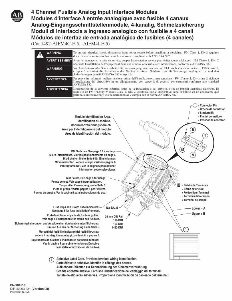
4 Channel Fusible Analog Input Interface ModulesModules d'interface à entrée analogique avec fusible 4 canauxAnalog-Eingangsschnittstellenmodule, 4-kanalig, Schmelzsicherung Moduli di interfaccia a ingresso analogico con fusibile a 4 canaliMódulos de interfaz de entrada analógica de fusibles (4 canales)(Cat 1492-AIFM4C-F-5, -AIFM4I-F-5)
Adhesive Label Card. Provides terminal wiring identification.Carte étiquette adhésive. Identifie le câblage des bornes.Aufklebbare Etiketten zur Kennzeichnung der Klemmenverdrahtung.Scheda etichette adesive. Fornisce l'identificazione del cablaggio dei terminali.Tarjeta de etiquetas adhesivas. Proporciona identificación de cableado del terminal.
1
1
Module Identification Area.Identification du module.
ModulkennzeichnungsbereichArea per l'identificazione del modulo
Area de identificación del módulo.
A1
B1
= Field-side Terminals= Borne exterieure= Feldseitiger Terminal= Terminale lato-campo= Terminal de campo
= Connector Pin= Broche de connexion= Steckerstift= Pin del connettore= Pasador de conector
8
1
159
DIP Switches. See page 6 for settings.Micro-interrupteurs. Voir les positionnements en page 6.
Dip-Schalter. Siehe Seite 6 für Einstellungen.Microinterruttori. Vedere le impostazioni a pagina 6.
Interruptores DIP. Vea la página 6 para obtener información sobre selecciones.
Fuse Clips and Blown Fuse Indicators: See page 5 for fuse installation/removal.
Porte-fusibles et voyants de fusibles grillés: voir page 5 l'installation et le retrait des fusibles.
Sicherungshalterungen und Anzeige einer durchgebrannten Sicherung. Ein-und Ausbau der Sicherung siehe Seite 5.
Morsetti dei fusibili e indicatori dei fusibili bruciati: vedere il montaggio/smontaggio dei fusibili a pagina 5.
Sujetadores de fusibles e indicadores de fusible fundido: Vea la página 5 para obtener información sobre
la instalación/extracción de fusibles.
Test Points. See page 5 for usage.Points de test. Voir page 5 pour utilisation.
Testpunkte. Verwendung, siehe Seite 5.Punti di prova. Vedere pagina 5 per l’utilizzo.
Puntos de prueba. Ver la página 5 para instrucciones de uso.
35 mm DIN Rail199-DR1199-DR4
1492-DR7
1492-EAJ35 Lower = A
Upper = B
PN-104510DIR 40063-331 (Version 08)Printed in U.S.A.
PN-104510DIR 40063-331 (Version 08) (2)
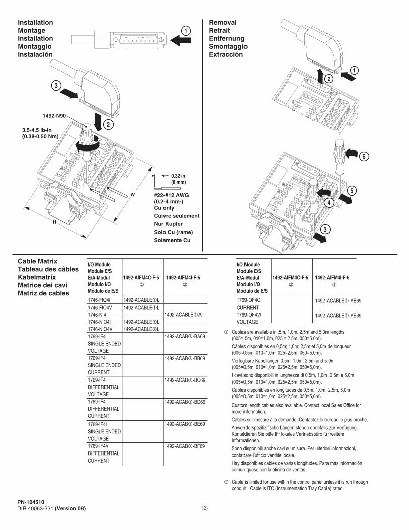
Cable MatrixTableau des câblesKabelmatrixMatrice dei caviMatriz de cables
RemovalRetraitEntfernungSmontaggioExtracción
InstallationMontageInstallationMontaggioInstalación
� Cables are available in .5m, 1.0m, 2.5m and 5.0m lengths (005=.5m, 010=1.0m, 025 = 2.5m, 050=5.0m). Câbles disponibles en 0,5m; 1,0m; 2,5m et 5,0m de longueur (005=0,5m; 010=1,0m; 025=2,5m; 050=5,0m). Verfügbare Kabellängen 0,5m; 1,0m; 2,5m und 5,0m (005=0,5m; 010=1,0m; 025=2,5m; 050=5,0m). I cavi sono disponibili in lunghezze di 0,5m, 1,0m, 2,5m e 5,0m (005=0,5m; 010=1,0m; 025=2,5m; 050=5,0m). Cables disponibles en longitudes de 0,5m, 1,0m, 2,5m, 5,0m (005=0,5m; 010=1,0m; 025=2,5m; 050=5,0m).
� Cable is limited for use within the control panel unless it is run through conduit. Cable is ITC (Instrumentation Tray Cable) rated.
Custom length cables also available. Contact local Sales Office formore information.Câbles sur mesure à la demande. Contactez le bureau le plus proche.Anwenderspezifizifische Längen stehen ebenfalls zur Verfügung.Kontaktieren Sie bitte Ihr lokales Vertriebsbüro für weitereInformationen. Sono disponibili anche cavi su misura. Per ulteriori informazioni,contattare l’ufficio vendite locale.Hay disponibles cables de varias longitudes. Para más informacióncomuníquese con la oficina de ventas.
1
1
2
2
3
#22-#12 AWG(0.2-4 mm2)Cu onlyCuivre seulementNur KupferSolo Cu (rame)Solamente Cu
0.32 in(8 mm)
3.5-4.5 lb-in(0.38-0.50 Nm)
1492-N90
3
5
6
4
1492-AIFM4C-F-5 1492-AIFM4I-F-5
1492-ACABLE�A
1492-ACABLE�L1492-ACABLE�L
1492-ACABLE�L1492-ACABLE�L
1746-FIO4I1746-FIO4V1746-NI41746-NIO4I1746-NIO4V1769-IF4SINGLE ENDEDVOLTAGE1769-IF4SINGLE ENDEDCURRENT1769-IF4DIFFERENTIALVOLTAGE1769-IF4DIFFERENTIALCURRENT
1769-IF4ISINGLE ENDEDVOLTAGE1769-IF4VDIFFERENTIALCURRENT
I/O ModuleModule E/SE/A-ModulModulo I/OMódulo de E/S
1492-ACAB�-BA69
1492-ACAB�-BB69
1492-ACAB�-BC69
1492-ACAB�-BD69
1492-ACAB�-BE69
1492-ACAB�-BF69
1492-ACABLE�-AE69
1492-ACABLE�-AE69
H
W
� �1492-AIFM4C-F-5 1492-AIFM4I-F-5
1769-OF4CICURRENT1769-OF4VIVOLTAGE
I/O ModuleModule E/SE/A-ModulModulo I/OMódulo de E/S
� �

(3)
3
PLC Analog Module
PLC Analog Module
1492-ACABLE�XX1492-ACABLE�YY
1492-ACABLE�XX1492-ACAB�YY
Earth GroundMasse TerreErdungMessa a terraTierra
DrainDrenaggioDrenaje
Cable Shield InstallationInstallation du câble blindé Kabelab-schirmungs InstallationInstallazione schermo del cavoInstalación de pantalla de cable
10-32 x .312 Thread RollType TT Screw (included with cable)
Vis Type TT à filetage roulé 10-32 x ,312(fournie avec le càble)
US-NR. 10-32 x ,312 GewindeschraubeTyp TT (wird mit Kabel geliefert)
Vite tipo TT Thread Roll 10-32 x ,312(inclusa con il cavo)
Barra roscada de 10-32 x 0,312 Tipo detornillo TT (incluído con cable)
DrainDrenaggio
Drenaje
Refer to your PLC modules Installation Manual for unique grounding requirementsVoir le manuel d'installation de vos modules PLC pour les conditions uniques de mise à la masse. Informationen zu besonderen Erdungsanforderungen finden Sie im Installationshandbuch für PLC-Module. Per requisiti specifici di messa a terra consultare il manuale di installazione dei moduli PLC. Consulte el manual de instalación de módulos PLC para conocer los requisitos sobre la conexión única a tierra.
Refer to Publications 1770-4.1 for generally recommended wiring and shield grounding guidelines.Voir les publications 1770-4.1 pour les conseils généraux de mise à la masse des câbles blindés.Sehen Sie Publikationen 1770-4.1 DE für generell empfohlene Verdrahtungs- und Abschirmungsanweisungen.Per procedure di cablaggio e messa a terra dello schermo generalmente consigliate consultare le pubblicazioni 1770-4.1.Consulte las publicaciones 1770-4.1 para obtener las recomendaciones más comunes sobre cableado y pautas para conexión a tierra.
NOTICE
REMARQUE
HINWEIS
AVISO
NOTA
NOTICE
REMARQUE
HINWEIS
AVISO
NOTA
PN-104510DIR 40063-331 (Version 08)
PN-104510DIR 40063-331 (Version 08) (4)
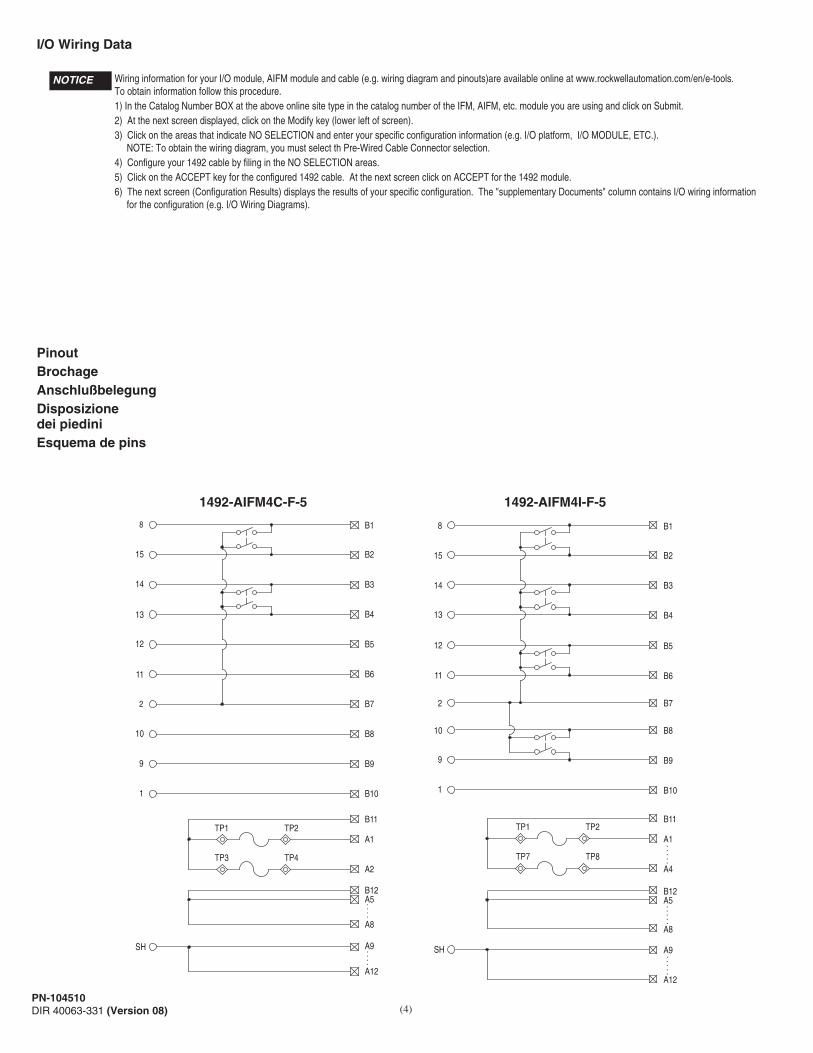
PinoutBrochageAnschlußbelegungDisposizionedei piediniEsquema de pins
I/O Wiring Data
1492-AIFM4C-F-5
B18
A8
B2
A5
B3
B4
B5
B6
B7
B8
B9
B10
B11
A2
A1
B12
15
14
13
12
11
2
10
SH
9
1
TP1 TP2
TP3 TP4
A12
A9
....
....
B18
A8
B2
A5
B3
B4
B7
B5
B6
B8
B9
B10
B11
A4
A1
B12
15
14
13
2
12
11
10
SH
9
1
TP1 TP2
TP7 TP8
A12
A9
.....
.....
.....
1492-AIFM4I-F-5
NOTICE Wiring information for your I/O module, AIFM module and cable (e.g. wiring diagram and pinouts)are available online at www.rockwellautomation.com/en/e-tools.To obtain information follow this procedure.1) In the Catalog Number BOX at the above online site type in the catalog number of the IFM, AIFM, etc. module you are using and click on Submit.2) At the next screen displayed, click on the Modify key (lower left of screen).3) Click on the areas that indicate NO SELECTION and enter your specific configuration information (e.g. I/O platform, I/O MODULE, ETC.). NOTE: To obtain the wiring diagram, you must select th Pre-Wired Cable Connector selection.4) Configure your 1492 cable by filing in the NO SELECTION areas.5) Click on the ACCEPT key for the configured 1492 cable. At the next screen click on ACCEPT for the 1492 module. 6) The next screen (Configuration Results) displays the results of your specific configuration. The "supplementary Documents" column contains I/O wiring information for the configuration (e.g. I/O Wiring Diagrams).

(5)
Test PointsPoint de testTestpunktPunto di provaPuntos de prueba
TP1
When using a 2-wire transmitter, test points can be used tomeasure input loop current:En cas d’utilisation d’un transmetteur deux-fils, il est possibled’utiliser les points de test pour mesurer le courant en boucled’entrée:Bei Verwendung eines Zweileiter-Senders können die Testpunktezur Messung des Eingangs-Schleifenstroms verwendet werden:Quando si utilizza un trasmettitore a due fili, i punti di provapossono essere utilizzati per misurare l'alimentazione al circuitodi ingresso:Los puntos de prueba se pueden usar para medir la entrada dellazo de corriente, cuando se usa un transmisor de 2 hilos:
0
0 1 2 3
1
2
3
ON
TP7TP5TP3
TP2 TP8TP6TP4
TP1
0 1
ON
TP3
TP2 TP4
1492-AIFM4I-F-5
1492-AIFM4C-F-5
CO
NN
ECT
UN
USE
D IN
PUTS
TO C
OM
MO
NC
ON
NEC
T U
NU
SED
INPU
TSTO
CO
MM
ON
1 Remove power Couper la tension Spannungsversorgung wieder anschließen Togliere corrente Quitar energía2 Remove fuse Retirer le fusible Sicherung entfernen Rimuovere il fusible Quitar fusible3 Attach meter probes Attacher les sondes du compteur Meßleitungen anschließen Collegare le sonde dello strumento di misurazinoe Conectar sonda de medida4 Re-apply power Remettre sous tension Spannungsversorgung wieder anschließen Ridare corrente Volver a energizar5 Measure loop current Mesurez le courant de la boucle Schleifenstrom messen Misurare la corrente del loop Medida del lazo de corriente
=Test Points Points de test Testpunkte Punti di prova Puntos de prueba
01
Fuse Installation / RemovalInstallation / retrait des fusiblesEin- und Ausbau der SicherungMontaggio / smontaggio dei fusibiliInstalación / extracción de fusibles
2
3
41
GOULD 34-015GLITTELFUSE 097023BUSSMAN FP-A3
5 x 20 mm(max. 2.0A per circuit; 12A per module)(max. 2,0 A par circuit; 12 A par module)(max. 2,0 A pro Stromkreis; 12 A je Modul)(max. 2,0 A per circuito; 12 A per modulo)(máx. 2.0 A por circuíto; 12 A por módulo)
PN-104510DIR 40063-331 (Version 08)

PN-104510DIR 40063-331 (Version 08)Printed in U.S.A.
SpecificationsSpécifications
SURGE SUPPRESSION follow the literature recommendations of the PLC module being used.SUPPRESSION DES SURTENSIONS se trouve à la suite de la littérature qui contient les recommandations relatives au module PLC utilisé.ÜBERSPANNUNGSSCHUTZ Bitte beachten Sie die Dokumentationsempfehlungen für das jeweils benutzte SPS-Modul.Per la SOPPRESSIONE DEI PICCHI TEMPORANEI, seguire le istruzioni riportate nella documentazione in dotazione al Modulo PLC utilizzato.SUPRESIÓN DE SOBRETENSIÓN, siga las recomendaciones indicadas en la documentación del módulo PLC respectivo.
Reference Publications: Refer to 1770-4.1and appropriate PLC I/O module installation manual.
#Terminals/CommonNombre de bornes/CommunAnzahl der Klemmen/gem. BezugspotentialN. terminali/comune# terminales/común
2
Maximum Recurring Peak Voltage �Tension de crele réurrente maximaleMaximale periodische HochstspannungTensione massima di cresta ricorrenteVoltaje de cresta iterativo máximo
600 Vp �< 2.0 mA10-60 VDC
Indicator Circuit CurrentCourant circuit voyantsStrom, AnzeigeschaltkreisCorrente circuito indicatoriIntensidad del circuito de indicadores
VoltageTensionSpannungTensioneVoltaje
Catalog No.RéférenceBestell-Nr.N. CatalogoReferencia
Technische DatenSpecifiche
Especificaciones
1492-AIFM4C-F-51492-AIFM4I-F-5
1492-AIFM4C-F-51492-AIFM4I-F-5
0
1
2
3
ON
CO
NN
ECT
UN
USE
D IN
PUTS
TO C
OM
MO
N
.561 lb.258 g.5 - 95% �
3.15 in. (80 mm) W3.27 in. (83 mm) H
2.74 in (69.5 mm) D
cULus (File: E10314, Guide No. NRAG)Suitable for use in Class 1 Div 2 Groups A,B, C and D Hazardous and Non-HazardousLocations.Temperature Code = T3C at 60°C �CE: Compliant for all applicable directivesFM Class 1 Div 2 Groups A, B, C and DTemperature Rating T3C = 60°C (J.I. 3000590 all except relay modules)
0° C - 60° C
DimensionsDimensionsAbmessungenDimensioniDimensiones
Approx. Shipping WeightPoids d'embarquement approximatifUngefähres VersandgewichtPeso approssimativo del caricoPeso aproximado al momento de embarque
StandardsNormesStandardsStandardEstándares
Catalog No.RéférenceBestell-Nr.N. CatalogoReferencia
Operating Temperature RangePlage températures de fonctionnementBetriebstemperaturbereichLimiti temperatura di funzionamentoRango de temperatura de funcionamient
Operating HumidityHumidité relativeBetriebsluftfeuchtigkeitUmidità di esercizioHumedad operativa
AIFM DIP Switch SettingsPositionnements des micro-interrupteurs AIFM
Connect unused inputs to commonConnectez les entrées inutilisées au communVerbinden Sie unbenutzte Eingänge zur MasseCollegare gli ingressi non usati al comuneConectar entradas sin usar al módulo común ON-CLOSED-For unused inputs. Jumpers input channel to module common.
ON-FERME-Pour les entrées inutilisées. Relie le canal d'entrée au commun du module.ON-GESCHLOSSEN-Für unbenutzte Eingänge. Überbrückt Eingangskanal zur Modulmasse.ON-CHIUSO-Per ingressi non usati - Collega il canale di ingresso al comune del modulo.ON-CERRADO-Para entradas sin usar. Conectar en puente los canales de entrada al módulo común.
Factory Position: Off / Open / Not connected to module common. Individually configure each input channel.Réglage usine: Off / Ouvert / Pas connecté au commun du module. Configurez individuellement chaque canal d'entrée.Werkseitige Position: Off / Open / Nicht zur Modulmasse verbunden. Konfigurieren Sie jeden Eingangskanal individuell.Posizione di fabbrica: Off / Aperto / non connesso al comune del modulo. Configurare individualmente ciascun canale di ingresso. Posición de fábrica: Off / Abierto / No conectado al módulo común. Configurar cada canal de entradas individualmente.
OFF-OPEN-For inputs connected to field devices. Does not jumper input to module common.OFF-OUVERT-Pour les entrées connectées aux appareils extérieures. Ne relie pas le canal d'entrée au commun du module.OFF-OFFEN-Für Eingänge, die zu Feldgeräten verbunden sind. Kein Überbrücken des Eingangs zur Modulmasse.OFF-APERTO-Per ingressi connessi a dispositivi di campo. Non collega l'ingresso al comune del modulo.OFF-ABIERTO-Para entradas conectadas a dispositivos de campo. No conectar en puente las entradas al módulo común.
AIFM DIP-Schalter-EinstellungenImpostazionidei microinter-ruttori AIFM
Interruptor DIP AIFM
� For transients > 600 Vp use a UL recognized suppression device rated at 2.5 kV withstand. Pour des transitoires > 600 Vp utilisez un dispositif de suppression certifié UL à 2,5 kV nominal de tenue. Für Einschaltstöße > 600 Vp verwenden Sie einen UL anerkannten Entstörer, der bewertet wurde bei 2,5 kV standzuhalten. Per transitori > 600 Vp usare dispositivo di soppressione riconosciuto da UL capace di sopportare 2,5 kV. Para transitorios > 600 Vp use un dispositivo de supresión reconocido UL clasificado con 2,5 kV.
� Non-condensing Sans condensation Nicht kondensierend Senza condensa sin condensación
� Power, input and output (I/O) wiring must be in accordance with Class I Division 2 wiring methods - Artticle 501-10(B)(1) of the National Electrical Code.
WARNING Explosion Hazard - substitution of components may impair suitability for Class I Division 2.Explosion Hazard - Do Not Disconnect Equipment unless power has been switched off or the area is known to be Non-Hazardous.

CONFIDENTIAL AND PROPRIETARY INFORMATION. THIS DOCUMENT CONTAINS CONFIDENTIAL AND PROPRIETARY INFORMATION OF
ROCKWELL AUTOMATION, INC. AND MAY NOT BE USED, COPIED OR DISCLOSED TO OTHERS, EXCEPT WITH THE AUTHORIZED WRITTEN
PERMISSION OF ROCKWELL AUTOMATION, INC.
Sheet
Size Ver
Of 11
B 0010000021664Dr. DateG. USHAKOW 02-11-10
MATERIALSIZE
FOLD
TWO SIDES PRINTEDBODY STOCK WHITE
BODY INK BLACK8-1/2" W x 5-1/2" H
FLAT
25-1/2" W x 11" H
Page Layout (25-1/2” Wide Sheet - Z-Fold)
Final Fold
5-1/2”
8-1/2”
Final Fold
8-1/2”
MATERIALSIZE
FOLD
TWO SIDES PRINTEDBODY STOCK WHITE
BODY INK BLACK8-1/2" W x 5-1/2" H
FLAT
(3) 8-1/2" W x 11" H
* If printed in smaller quantites (approximately 1000 or less a year), it is acceptable to use three 8-1/2” x 11” sheets (printed front and back on each) and stapled together.
Page Layout *(Three 8-1/2” Wide Sheets - Stapled)
SPECIFICATIONS FOR6 PAGE INSTRUCTION SHEET8-1/2” W x 5-1/2” H - FINAL FOLD
11"
8-1/2"8-1/2"
Front Side
Page 2
Back Side
Page 1
Front SidePage 3
Back SidePage 6
Front Side
Page 4
Back Side
Page 5
8-1/2"
5-1/2”
PN-12345DIR 100000000 (Version 00)Printed in U.S.A.
PN-12345DIR 100000000 (Version 00)Printed in U.S.A.
Note: After folding---Printed in (Country where printed)** and instruction sheet number in lower left corner should be visible.
** The printing vendor may change the instruction sheet files to show the correct country.
Note: After folding---Printed in (Country where printed)** and instruction sheet number in lower left corner should be visible.
** The printing vendor may change the instruction sheet files to show the correct country.
11”
8-1/2" 8-1/2"
Back SidePage 1
8-1/2”
Front SidePage 2
Back SidePage 6
Front SidePage 5
Stapled
Back SidePage 4
Front SidePage 3