3o ! i 36 carousel, a toy turbine wheel, a teeter-totter bucket and a water shower bucket. referring...
TRANSCRIPT

United States Patent (113,577,675 72 inventors Frank Kohner
New York, N.Y.; t Albert Stubbmann, Franklin Lakes, N.J.
21 Appl. No. 841,872 22 Filed July 15, 1969 45 Patented May 4, 1971 73 Assignee Kohner Bros., Inc.
East Paterson, N.J.
54 CHILD'S BATHINGTOY 18 Claims, 12 Drawing Figs.
(52) U.S. Cl........................................................ 46/41 (5) Int. Cl................ ... A63h 29/10 50 Field of Search.................................... ........ 46/41,42,
91.93 56. References Cited.
UNITED STATES PATENTS 2,703,407 3/1955 Henoch et al................. 46/41X 2,968,120 111961 Reed............................ 46/91 3,213,565 10/1965 Grosz ........................... 46/91 3,425,152 2/1969 Foulkes........................ 46/41
40
3O
8 36 ! I
Primary Examiner-Louis G. Mancene Assistant Examiner-D. L. Weinhold Attorney-Kirschstein, Kirschstein, Ottinger and Frank
ABSTRACT: The bathing toy includes a casing to be located on the inside wall of a bathtub. The casing is supported by straps slung over the tub wall and fastened to the outside wall by suction cups. Mounted in the casing is a water pump, the nozzle of which can be rotated to direct a stream of water from the pump for activating selected water powered com ponents. Bathtub water is drawn to the pump from an intake tube immersed below the bathtub water level. With the nozzle pointed in one direction, the water stream strikes a carousel, rotating the carousel figures. The water drains from the carousel to a teeter-totter bucket from which it is discharged into the bathtub. If the nozzle is pointed in another direction, the water stream actuates a turbine wheel and subsequently drains into a bucketlike container seated within the casing. The container includes a circular dish pivotally mounted on the bottom. The circular dish and the container bottom have a plurality of holes which are aligned when the dish is rotated to a certain position. When the holes in the dish and the bucket bottom are in alignment and the bucket is lifted out of the con tainer, the water flows from the bucket in tiny streams simulat ing a bathing shower. The pump is so constructed that it has a protracted discharge period after each actuating down stroke of its operating handle.
PATENTED MAY 497 3,577, S75 SHEET 1. OF 3
(N 38 30 fa NNEST /7A É). Fi 36
A 132 S& 4. A 88 &
INVENTOR. FRANK KOHNER ALBERT STUBBMANN
&4, w 6aed-4, (% et, '?-rel/ ATTORNEYS

PATENTED MAY 4197) 3,577,675 SHEET 2 OF 3
/ ysea a 4.
78
78
6
S. Z a. 7. 5 8
V
6.
2. is 7
;
s INVENTOR.
FRANK KOHNER BY ALBERT STUBBMANN
F G. 2 A...a, ta-4, 4% // ATTORNEYS

3,577,675 PATENTED YAY 497 SHEET 3 OF 3
R=<<<<<<<rs:
8
INVENTOR. KOHNER
BY ALBERT STUBBMANN
f6.4/-, acaea/a, 4%iya f/au/.
FRANK
F G. 7 AT TORNEYS

CHILD'S BATHINGTOY
BACKGROUND OF THE INVENTION 1. Field of the Invention Bathing toys which are adapted to be used in a bathtub. 2. Description of the Prior Art Many mothers have found that it is often a difficult task to
induce their children to enter a bathtub filled with water. One solution to the problem is to provide bathtub toys which will 10 attract the child's attention and render the evening bath more enjoyable. Some of the previously used bathtub toys were floating ob
jects while others were mountable on the bathtub. Of the bathtub toys which were mountable on the bathtub. Of the 15 bathtub toys which were mountable on the bathtub, con siderable difficulty has been encountered in maintaining the toys in their proper position as the soapy water within the tub usually splashed the toy and loosened its mounting arrange ment. 20 Furthermore, the previous bathtub toys were not customari
ly capable of maintaining the child's sustained attention because they did not provide sufficient amusement activity. .
Additionally lacking the prior bathing toys was a provision for utilizing a single hand operated power source capable of 25 selectively actuating any one or more of a plurality of action components all included in a single toy.
SUMMARY OF THE INVENTION It is an object of the present invention to provide a child's
bathing toy which is so constructed that it is not subject to any of the foregoing disadvantages. More specifically, it is an object of the present invention to
provide a child's bathing toy which is simple and rugged in 35 construction, yet can be fabricated by mass production methods at an appreciably lower cost than prior toys designed to serve the same general function.
it is another object of the present invention to provide a child's bathing toy which is mounted on the inside wall of a 40 bathtub by a plurality of straps which are secured adjacent their opposite ends to the outside wall of the bathtub. . . Yet another object of the present invention is to provide a child's bathing toy wherein a jet of bathtub water activates visually attractive rotating parts. 45 A further object of the present invention is to provide a
child's bathing toy wherein amusement components are selec tively operated by a jet of water from a pump which draws bathtub water and in which the flow direction of the jet is changeable at will. Another object of the present invention is to provide a
child's bathing toy of general character described wherein a toy water pump is so constructed so as to provide a sustained jet output capable of activating a movable component for a sustained period of time and thereby maintaining a child's in terest. A still further object of the present invention is to provide a
child's bathing toy of general character described which in cludes a two-piece molded turbine water wheel which is so 60 constructed that each of the pieces includes circumferentially spaced turbine vanes, portions of which overlap the vane ring of the opposite piece to form a composite turbine with every other vane being formed from the same piece. Yet another object of the present invention is to provide a 65
child's bathing toy of general character described wherein a toy bucket is filled with bathtub water and the water is sub sequently discharged from the bucket by a child through a plu rality of selectively operable spaced openings in the bottom thereof, thus simulating a shower. 70 A further object of the present invention is to provide a
child's bathing toy of the general character described wherein a manually operable water pump draws bathing water from the tub and discharges the same toward any one or more of a plurality of water powered components.
3,577,675
30
55
2 A still further object of the present invention is to provide a
child's bathing toy of the general character described wherein the jet discharge from a water pump flows from one rotating component to a subsequent component located at a lower elevation. Another object of the present invention is to provide a
child's bathing toy of the general character described wherein a quantity of bathing water is collected at an elevation above the water level of the bathtub and is subsequently drained to a teeter-totter bucket which discharges into the bathtub. Other objects of the invention in part will be obvious and in
part will be pointed out hereinafter. The invention accordingly consists in the features of con
struction, combinations of elements and arrangements of parts which will be exemplified in the child's bathing toy hereinafter described and of which the scope of application will be in dicated in the appended claims.
BRIEF DESCRIPTION OF THE DRAWINGs In the accompanying drawings in which are shown various
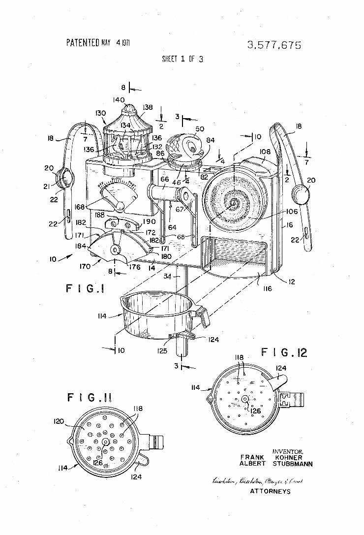
possible embodiments of the invention, FIG. 1 is a perspective view, partially exploded, of a child's
bathing toy constructed in accordance with and embodying the invention and showing flexible straps, one end of each of which is fastened to the sides of the toy and which straps suspend the toy on the inside wall of the bathtub, the straps being secured at their other ends to the outside wall of the bathtub by suction cups;
FIG. 2 is a fragmentary side-to-side sectional view taken substantially along the line 2-2 of FIG. and illustrating the pump nozzle structure along with the water wheel turbine con struction;
FIG. 3 is a fragmentary front-to-back sectional view taken substantially along the line 3-3 of FIG. 1 and illustrating the pump structure in detail;
FIG. 4 is a fragmentary sectional view taken substantially along the line 4-4 of FIG. 1 and showing the pump structure and a pump actuating lever mechanism;
FIG. 5 is a fragmentary sectional view taken along the line 5-5 of FIG. 4 and showing further details of the pump struc ture along the pump actuating lever mechanism;
FIG. 6 is a fragmentary sectional view taken substantially along the line 6-6 of FIG.3 and illustrating a valve assembly used in the pump;
FIG. 7 is a sectional view taken substantially along the line 7-7 of FIG. 1 and illustrating the pump nozzle directing a jet of water to a toy carousel;
FIG. 8 is a sectional view taken substantially along the line 8-8 of FIG. 1 and showing a quantity of water standing in a collecting tank beneath the carousel;
FIG. 9 is a fragmentary auxiliary view taken substantially along the line 99 of FIG. 8 and showing portions of a flow regulating valve which controls the flow of water as it drains from the collecting tank into a teeter-totterbucket;
FIG. 10 is a sectional view taken substantially along the line 10-10 of FIG. 1 and illustrating the construction of the turbine wheel and a shower bucket positioned under the wheel and which collects the spent water from the turbine wheel; and
FIGS. 11 and 12 are top and bottom views, respectively, of the shower bucket.
DESCRIPTION OF THE PREFERREDEMBODIMENT The bathing toy is formed of a compartmentalized housing
which is mounted on the inside wall of a bathtub to amuse a young child and induce him to bathe. The casing is suspended on the bathtub wall by flexible straps which are secured to the outside wall of the bathtub by suction cups. The central fea ture and motive means of the toy is a hand operated pump which draws bathing water from the tub and forces it from a nozzle. The jet of water from the nozzle can be directed to various action components of the toy and cause them to be ac
75 tivated. Among the water actuable components are a toy

3 carousel, a toy turbine wheel, a teeter-totter bucket and a water shower bucket.
Referring now in detail to the drawings, the reference nu meral 10 denotes a bathing toy constructed in accordance with and embodying the invention. The toy includes a molded plastic housing 12 having front 14 and rear 16 sections. The abutting common peripheries of these sections are flanged and secured together by conventional means such as an adhesive or heat seal. To suspend the toy on the interior surface of the bathtub
wall; two flexible plastic straps 18 are provided. The straps are mounted on the rear portion of the housing at opposite side edges thereof. Conventional fastening means, e.g. adhesives, rivets or heat seals, are used to secure the straps to the sides of the housing. A suction cup 20 is secured adjacent the opposite end of each strap. The rear surface of each suction cup in cludes a unitarily formed mushroom headed protuberance 21 which facilitates the fastening of the suction cup to the strap. The suction cup protuberance is inserted through any selected one of a plurality of elongate longitudinally spaced slits 22 ad jacent the free end of each strap. The mushroom head is forced through a selected slit so that each suction cup is fastened in a manner similar to that of a button which extends through a buttonhole. To adjustably accommodate for various types of bathtubs
wherein the thicknesses of the bathtub walls differ, there is, as noted, more than one slit in each strap so that the suction cup may be adjustably positioned and, thus, the effective length of the strap may be varied. This is important because the eleva tion of the bathing toy above the level of the bathing water is critical to a certain extent, i.e., a bathing water intake tube must extend into the bathing water to permit the drawing of water by the pump. . To mount the toy, the suction cups are moistened and then are attached to the exterior of the surface of the bathtub. The straps extend over the top rim of the bathtub wall and downwardly along the interior bathtub wall surface. The bathtub toy is thus suspended from the outside surface of the bathtub wall. With the suction cups positioned on the outside surface of
the bathtub wall, the soapy bathtub water which has a reduced surface tension does not contact the suction cups and, there fore, the suction cups will not easily come loose. When the toy is mounted on the inside wall of the bathtub,
the child's attention will be directed to a pump 24 which ac tivates and powers the action components of the toy. The pump is mounted within a central portion of the housing between the front and rear sections and within a compartment of rectangular horizontal cross section. The compartment is formed by abutting flanges 26 (see FIG. 4) extending rear wardly from the front section 14 and flanges 28 extending for wardly from the rear section 16. The pump structure is shown in detail in FIGS. 2-6. It in
cludes a piston 28 supported by an open ended hollow verti cal stem 30' (see FIG. 3), both of which are stationary, and a cylinder 30 which moves vertically relative to the piston. The piston is formed of two resilient annular discs 29 mounted in abutting back-to-back relation and secured in such position between spaced annular ledges of a hub 29'. The hub is fastened to the stem adjacent and around the open lower end thereof. Each disc has an outwardly flaring tapered sealing flanged peripheral edge. The top of the stem is supported, as soon will be seen, in a manner such that it can experience rota tion but no axial movement. At the bottom of the cylinder 30 there is a central inlet
opening 32 communicating with the bottom end of the stem 30'; a flexible plastic intake hose 34, running into the tub water, is connected thereto. Inwardly of the opening 32, a one-way (check) inlet (inflow) valve 36 is positioned. This valve includes a flat horizontal disc 38 which is free to move upwardly to a limited extent away from its seat around the opening 32. Such movement is restrained by a squat U-shaped cross member (cage) 40 which is connected to the bottom of
3,577,675
5
O
15
20
25
30
35
40
45
50
55
60
65
70
75
4 the cylinder and the bight of which is elevated above the open ing and extends diametrically thereacross. When the cylinder is moved downwardly relative to the stationary piston, a vacuum is created under the piston, opening the valve 36. As a . result, water is drawn up the tube 34, past the disc 38 and into the cylinder 30 beneath the piston 28". Once the cylinder under the piston is filled, the disc will close by gravity to seal the opening as the disc rests on its seat around the opening 32. The disc prevents the flow of water in the reverse direction out of the bottom of the cylinder. A helical coil spring 44 is concentrically mounted about the
piston stem and is compressed between the top of the piston and the top of the cylinder. The spring is further compressed when the cylinder is moved downwardly. When the cylinder is released, the spring releases its stored energy to urge the cylinder upwardly for a protracted (sustained) discharge stroke. The open upper end of the piston stem 30' is capped by one way outflow (discharge) check valve 45 identical in structure to the valve 36. This valve opens into a dome-shaped nozzle chamber 46 (see FIG. 2), the upper end of which leads into a nozzle passage 48. The nozzle passage is located within a hollow toy FIGURE 50 which may be of any amusing form, e.g., a fish having the discharge end of the nozzle at the mouth thereof. A mounting plate 52 is fixed to the lower edge of the nozzle
chamber. The plate 52 includes a flat circular base having a vertically upwardly directed stepped flange 54, which abuts the side edges of the nozzle chamber and insures a water tight seal. The bottom edge of the nozzle chamber is additionally sealed against the upper surface of the mounting plate. The mounting plate periphery extends beyond the flange 54 and is mounted for rotation within a circular channel 56 in the top of the housing. The lower surface of the mounting plate includes a concentric hollow tubular projection 58 which tightly en gages and is sealed against the piston stem, thus preventing any leadage of water. The engagement between the mounting plate and the upper and lower edges of the circular channel prevent the stem from moving vertically. As the cylinder is drawn downwardly, air within the cylinder
above the piston will exhaust through a clear space 42 between the tubular projection (or the stem) and a central opening in the top of the cylinder. - The manner in which the pump cylinder is mounted within
the toy housing and the linkage by which the cylinder is verti cally reciprocated are illustrated in FIGS. 2, 4, 5, and 7. Two flanges 60 (see FIG. 4) of L-shaped cross section project for wardly from the pump cylinder 30. The front webs of said flanges 60 lie in a common vertical plane. Elongate slots 62 are formed in these front webs. To actuate the cylinder, a U shaped pump lever 64 is provided. The lever includes a tubu lar pump handle 66 and parallel legs 67. The handle is mounted between spaced projecting bosses 67' adjacent the forward end of each leg and the legs extend through vertically elongate slots 68 in the front wall of the casing and through the slots 62 of the L-shaped flanges. The opposite (rear) end of each leg is pivotally secured to one of a pair of flanges 70, which project from the rear wall of the housing (see FIG. 5). For this purpose each flange 70 includes a projecting lug 72. The lugs 72 extend through circular openings adjacent the rear ends of the legs to form the aforesaid pivotal mounting and lug heads are subsequently flattened (see FIG. 4) to preventinadvertent disassembly. When the pump handle is pulled downwardly, the legs 67
rotate about the lugs 72 and the lower edge of each leg bears against the bottom of each slot 62. The legs thus cause the cylinder 30 to move downwardly. During this operation, bathtub water is drawn in through the intake tube, past the inlet check valve 36 and into the cylinder 30 below the piston 28. Concurrently the pring 44 is compressed, When the handle is released, the spring forces the cylinder
upwardly causing the water trapped within the cylinder beneath the piston (the valve 36 is closed) to flow through the piston stem. The water flows through the outlet check valve

3,577,675 5
45 into the nozzle chamber. The nozzle passage 48 is small enough to create a considerable constriction to the free flow of water. Due to the proportioning between the force exerted by the spring and the diameter of the constriction, the spring will take in the neighborhood of 10 to 12 seconds to fully discharge the water collected within the cylinder. Thus, a child using the toy will not be required to constantly move the pump handle in order to maintain a steady flow of water. It will be noted that the child applies force to the handle only on the downstfoke thereof, the reaction to this force creating ten sion in the flexible support straps. The upstroke (discharge) of the pump is activated by the spring, not upward manual force applied to the handle, which would not be possible with a suspension mounting for the toy 10. To stabilize the movement of the piston cylinder, the edges
the surface of the compartment walls. The track 76 is com posed of a plurality of horizontally disposed strips 78. The strips are preferably molded in one piece with the flanges 26 and 28. Each strip extends across the width of the compart ment wall and includes a grooved portion 80 which is of a width slightly larger than the thickness of the front face of the L-shaped flange. All of the grooved portions are vertically aligned so that a track is thus provided and the movement of the cylinder is thereby guided. The edges of the front faces of the L-shpaed flanges ride up and down within the aligned grooves when the cylinder is in motion. The water jet from the pump nozzle passage may be
directed in either of two extreme positions, one of which is shown in FIG. 1 and the other in FIGS. 6 and 7. It should be noted that the limitation of the rotational movement of the nozzle chamber 46 is caused by a radial abutment stop 82 on the exterior of the chamber (see FIG. 1) which projects above the mounting plate flange 54. The abutment stop will limit the rotational movement of the nozzle chamber and hence the nozzle FIGURE by contacting shoulders 84 and 86 which pro ject above the circular channel 56 of the casing. Thus, the noz zle chamber may rotate until the abutment stop contacts the stops of the circular channel which are spaced apart approxi mately 180. With the nozzle oriented as indicated in FIGS. 1 and 2, the jet of water is directed to an activity turbine wheel which is sontained within the housing. The turbine wheel is formed of front 88 and rear 90 half-wheels (see FIG. 2). Each of the half-wheels is of one-piece molded plastic construction and includes an outwardly tapering central hub 92 (see FIG. 10). A keyed axle 94 is positioned so that its ends extend through the central openings in the hubs to which it is fast. Each half-wheel also has an annular flat vertical portion 96 and a thin outwardly tapered vane ring 98 leading to a vertical outwardly offset annular portion 100. Six equidistantly spaced turbine buckets (vanes) 02 are unitarily formed within each of the half-wheels. A portion of each bucket projects beyond the interior of the associated half-wheel in a direction parallel to the axis of rotation of the wheel. The projecting portion is tapered to mate with and overlies the tapered vane ring 98 of the opposed half-wheel. Alternating buckets of the composite water wheel are a part of the same half-wheel and the succes isive assembled buckets are spaced apart half the distance of the buckets on the same half-wheel.
This structure greatly facilitates the formation of the half wheels by molding techniques and further facilitates assembly of the composite turbine wheel. Once the two halves are brought together, they are secured by conventional means, e.g. adhesive or heat welds, at their abutting surfaces. The central openings through the hubs 92 are square to ac
commodate a square keyed section of the axle 94 so that the
10
15 of the L-shaped flanges are engaged in a track 76 formed in
25
30
35
40
45
50
6 The front end of the axle projects through an opening in the
front wall of the housing. It should be noted that the cylindri cal diameter at the rear end of the axle and the bore through the rear wall and boss are larger than the square section of the axle so that the axle may freely be inserted into the housing. To provide a further amusement function, a plastic disc 106
having a suitable animatable design, such a multihued spirals as illustrated in FIG. 1 is affixed to the cylindrical end of the axle which projects through the front of the housing. This disc 106 is formed with a concentric circular flange having a bore of a diameter approximately equal to the diameter of the front end of the axle. The flange is forced over said end of the axle and is secured thereto by suitable means. A slight clearance remains between the rear end of the flange and the front face of the housing (see FIG. 10) so that when the turbine wheel rotates, the disc 106 will rotate without interfering with the front of the housing. The water jet from the pump nozzle is directed as to strike
the turbine buckets at the top of the wheel and cause the tur bine wheel to rotate. The axle 94 rotates with the disc 106. A child will be greatly amused by not only the pump which main tains a sustained flow after release of the handle but also by the spinning turbine wheel and disc. The churning action of the wheel on soapy water also tends to form soap bubbles to the further delight of the child.
In order to prevent excessive splashing of water, as the water strikes the turbine buckets, a shield 108 (FIG. 1) is situ- . ated on the upper surface of the housing and partially overlies the portion of the wheel that projects above the housing, leav ing a space for the jet to impinge on the buckets. The water wheel is located in a compartment (se FIG. 2) which is closed at its bottom by a horizontal wall 110. The wall includes an opening 112 through which the water drains from the turbine buckets, The water which flows through the opening 112 runs into a
bucket 113 which is removably seated on a shelf 116 formed by the lower wall of the housing. The front wall of the housing is open to permit access to the shelf and ready manual removal of the bucket. When the bucket is filled with water, a further play activity
is available for the child because the bucket includes a means whereby it may simulate a shower. For this purpose, the bucket includes a plurality of openings 118 (see FIG. 12) mu tually arranged in an orderly pattern, in the bottom surface thereof. The openings 118 are selectively blocked to prevent the water which is collected in the bucket from draining therethrough. This is accomplished by providing a shallow dish 120 within the bucket in abutting contact with the bottom and a squat portion of the sidewalls. The dish 120 likewise in cludes a plurality of openings 122 arranged in the same pat tern and a projecting lug 124 for manipulation. The lug ex tends through a slot 125 in the sidewall of the bucket; the ends
55
60
65
axle will rotate with the turbine wheel. The axle is cylindrical adjacent its rear end and is journaled within a cylindrical bore in a boss 103 which projects from the rear wall of the housing. The rear end of the axle includes an enlarged head 104. The
... axle is inserted through the bore which also passes through the rear wall of the housing with the axle head serving as a retain ing member to prevent the entire axle from slipping forwardly through the housing.
70
75
of the slot determine the extreme positions of the lugin one of which the openings 118 are blocked. The slot is blocked to the passage of water by the erect side of the dish. The dish is pivotally mounted at its center on the bottom of the bucket by a rivet 126. In order to unblock the openings 118, the lug is moved to one extreme position in which the openings 122 of the disc are in alignment with the openings 118 at the bottom of the bucket. This permits water to descend from the bucket in a plurality of tiny streams each of which is issuing from one of the openings 118 with the entire effect simulating a bathing shower, The nozzle may be rotated to a different position in which
the jet of water issuing therefrom is directed to another activi ty play component, e.g., a carousel 130, as is illustrated in FIG. 7. The carousel 130 includes a vertical shaft 132 which is journaled at its lower end in a step bearing extending upwardly from the top of the housing. The lower tip of the shaft is pointed to facilitate rotation of the carousel by reducing fric tion between the shaft and the bearing. A plurality of radial webs 134 extend from the shaft and at their outer ends support vertical generally flat characters 136 that are substantially perpendicular to the webs. A carousel roof 138 is mounted

3,577,675 7
above the FIGS. and a dome shaped decorative cap 140 is positioned atop the roof. The roof is supported by a backsplash plate 144 which is in the shape of a mutilated cylinder. The backsplash plate not only serves to support the roof but also acts as a water splash guard, thus preventing ex cessive splashing of water from the spinning characters. The upper end of the carousel shaft is journaled within the roof and extends into the cap. As illustrated in FIG. 7, the water jet issuing from the nozzle
may be aimed so that it not only strikes successive individual FIGS. 136 but also strikes successive webs at points remote from the shaft 132 thereby rapidly spinning the shaft and characters. The nozzle cannot be turned far enough for the jet to be directed at the carousel shaft to thereby immobilize the carousel. The water which strikes the carousel drains through a plu
rality of openings 146 formed in the top of the housing and into a storage compartment 148 having a bottom wall formed by two horizontally disposed flanges 150 and 152, which ex tend inwardly from the front and rear walls, respectively, of the casing. The water drainage from the carousel may thus be accumulated in the compartment and stored to provide power for animation of a further activity play component. Such further activity play component which utilizes the
stored water is a teeter-totter bucket. The bucket is selectively fed water through a valve 154. The valve 154 includes a circular tunnel passageway 156
(see FIGS. 8 and 9) extending in a front-to-back direction through the front wall 14 of the casing and leading into the water storage compartment 148. The front wall is thickened in the region of the passageway. The passageway serves as a valve body. A tubular valve plug 160 rotates within the valve body with its inner open end exposed to the water storage compartment. The outer end of the valve plug is capped. The plug 160 has an outer diameter which is approximately equal to that of the passageway. A radially extending tab 62 pro jects from the inner end of the plug and rides against the inner end of the thickened portion of the front wall to prevent the withdrawal of the valve plug. A downwardly directed water opening 164 located in the inwardly extending portion of the front wall and communicates with the passageway. A radial orifice 166 extends through the valve plug 160 in the vertical plane of the opening. The plug 160 may be rotated until the orifice is brought into alignment with the opening 164 at which point water will flow from the storage compartment through the valve plug and down the aligned opening 164 and orifice 166. A handle 168 is attached to the forward end of the valve plug 160 to provide a lever by which the plug 60 may be rotated to vary the degree of alignement between the open ing 164 and thereby to regulate the rate of water flow through the valve. With the handle 168 in the off position, shown in FIG. 1, the
opening 164 and orifice 166 are not in alignment so that the water in the storage compartment cannot flow through the valve. However, the handle 168 may be turned to bring the opening and orifice into partial alignment whereupon the water will flow through the valve. In this position the water flow is less than the maximum. A maximum water flow will be achieved when the handle is turned to the "fast" position shown in FIG. 1 at which point the opening and orifice are fully aligned. A teeter-totterbucket 170 is mounted on an inset portion of
the front wall beneath the opening 164 of the valve. The teeter-totter bucket includes two water receiving pockets 171 separated by a dividing wall 172. The entire bucket is jour maled on a horizontal pin 174 having an enlarged head 176, the rear end of which is fixed in an opening 178 in the front wall. Each of the pockets includes a sloped lower wall 180, a rear wall 182 and a front wall 184. A bucket stop member is provided to limit opposite rotating movements of the water collecting bucket. The stop member is formed of a central up ward protrusion 186 on the rear wall 182 between the pockets. The protrusion projects into an overhanging com
10
5
20
25
30
35
40
45
50
55
8 partment 188 on the front wall. The compartment 188 has sidewalls 190 which contact the stop member to limit the pivotal movement of the bucket. The bucket is in unstable equilibrium. The pivot pin is
directly beneath the opening of the valve 154 and water flow ing from the storage compartment will drop directly into either compartment of the bucket depending upon the posi tion of the bucket. In the illustration shown in FIG. 1, the bucket is empty and is shown in a central position wherein the flow of water will be deposited in both buckets as the dividing. wall 172 is in alignment with the opening of the valve. The slightest imbalance in the amount of water collected in either pocket will tilt the bucket in a direction which will discharge the water from the pocket having the greater amount of water. in the discharged position the lower wall 180 of the pocket will not be sloping upwardly as illustrated in FIG. 1 but will be either horizontal or slightly downwardly sloping. In such posi tion drainage of water from the pocket will be assured and furthermore, the opposite pocket will be in direct alignment with the discharge opening of the valve. Said opposite pocket, while unfilled and partially filled, will, with the assistance of the support afforded by contact of the stop member with a sidewall 190, be in stable equilibrium. With said opposite pocket in alignment with the discharged opening, this other pocket will fill with water until the weight of the water con tained therein becomes sufficient to overbalance the bucket and cause the same to pivot in a direction which will discharge the water from this opposite pocket.
It should be noted that the center of gravity of the entire teeter-totter bucket is such that when both pockets are empty and one of the pockets is in its water discharged position, the bucket will tend to maintain such position. As the empty pocket which is now filling with water accumulates a quantity of water the center of gravity of the bucket will be shifted and when the water accumulated is sufficient to shift the entire center of gravity to the opposite side of the pivot pin, the bucket will pivot about the pin and discharge the pocket which has just accumulated the water and will position the other empty pocket beneath the valve opening. With the present invention, it can be seen that the bathing
toy not only provides multiple activity components, all of which sustain a child's interest while bathing, but that all of the components are coordinated with at least one other com ponent so that a continuous train of activity following the course of the flowing water will ensue. Thus, the toy serves an educational function as well as an amusement function.
In use the toy is mounted on the inside of the bathtub, as previously described, with the intake tube 34 positioned below the bathtub water level. When the child pulls down on the pump handle, the pump cylinder fills with water beneath the piston and when the handle is released, the compressed spring causes the water to discharge from the cylinder through the hollow piston stem and through the pump nozzle. This discharge, as previously noted, takes a considerable period of time and the resulting flow of water from the pump nozzle is in a sustained steady jet. When the pump nozzle is aimed in one direction, the water
60 jet causes a turbine wheel to rapidly rotate and spin an optical illusion design mounted on a disc which is secured to the tur bine axle. The discharge of water from the turbine is utilized
65
70
75
to fill the shower bucket so that the initial flow of water from . the pump serves two functions to wit: The rotation of the tur bine and illusion disc and the filling of the sublocated water collecting bucket which when filled provides a shower toy. With the nozzle pointed in the other direction, the flow of
water issuing therefrom impinges upon carouse characters and/or webs (paddles) causing the carousel to rapidly rotate. The drainage of this water fills a water storage compartment which is dischargeable through a valve controlled by the child. The valve discharge is further utilized to operate a sublocated teeter-totter bucket.
In whichever of the two positions the pump nozzle is directed, the water finally returns to the bathtub. Thus, a

3,577,675 minimal amount of water splashing outside of the tub area is achieved.
In fact, the use of this toy will induce the child not to splash water from the tub as his interest will be immediately centered about the toy.
It thus will be seen that there is provided a child's bathing toy which achieves the several objects of this invention and which is well adapted to meet the conditions of practical use. As various possible embodiments might be made of the
above invention and as various changes might be made in the embodiment set forth, it is to be understood that all matter herein described or shown in the accompanying drawings is to be interpreted as illustrative and not in a limiting sense. We claim: 1. A child's bathing toy capable of attracting a child's atten
tion and inducing the child to regularly bathe, said toy com prising: a housing, a pump mounted within said housing, said pump having inlet and outlet orifices, conduit means intercon necting said inlet orifice with bathing water, a nozzle, said noz zle being interconnected with said outlet orifice, said pump further including check valves for preventing the flow of water from the pump to the bathtub water through the conduit means, while permitting the pump to draw bathing water through the conduit means, a plurality of water play activity components mounted on said housing and means to mount the nozzle for movement in a path so that the flow of water from said pump is directable to any selected water activity play component to actuate the same. .
2. A child's bathing toy constructed in accordance with claim 1 wherein at least one of said water play activity com ponents is pivotally mounted on the housing and moves as the water stream from the pump strikes the component.
3. A child's bathing toy constructed in accordance with claim 1 wherein a second water play activity component is
10
10 the water which drains from the activity component at the higher elevation.
9. A child's bathing toy suitable for use within a bathtub and for maintaining a child's attention, said toy including a hous ing, a pump mounted within said housing, said pump compris ing a pump cylinder mounting for reciprocal motion, a sta tionary pump piston, said piston including a sliding seal between the abutting periphery of the piston and the inner sur face of the cylinder, said pump including an inlet orifice in the bottom end of the cylinder beneath the piston, the piston in cluding a central orifice and a piston stem, said piston stem being hollow and interconnected at one of its ends to the
5
20
25
30
35 mounted on the housing, said second component being spaced from said first component, whereby either of said components may be selectively actuated by the child as he directs the flow of water from the pump.
4. A child's bathing toy constructed in accordance with claim 1 wherein. the flow directing means includes means mounting said nozzle for movement in a fixed path.
5. A child's bathing toy constructed in accordance with claim 1 wherein a second activity component is located at a lower elevation than a first component, flow of water from the pump activating the first component at a higher elevation and draining therefrom to activate the second component at the lower elevation;
6. A child's bathing toy constructed in accordance with claim Swherein the housing includes a water storage compart ment, said compartment being at an elevation between the two activity components and storing water drainage from the first activity component, and a valve means selectively opera ble to cause the water collected in the storage compartment to discharge by gravity therefrom for utilization by the second activity component.
7. A child's bathing toy constructed in accordance with claim 5 wherein the second activity component includes a bucket, said bucket having a plurality of opening in the bot tom thereof in a certain pattern, a plate pivotally mounted on the bucket bottom, said plate having a plurality of openings in the same pattern, said plate further including means to manually pivot said plate relative to said bottom from a posi tion in which the openings are disaligned so as to block flow of water therethrough to a position in which the openings are in alignment, thereby causing water collected in the bucket to drain from the bucket in a plurality of streams simulating a shower.
8. A child's bathing toy constructed in accordance with claim 7 wherein the bucket is removably positioned within the housing, the front wall of the housing including a recess and the bottom of the housing including a shelf, said bucket nor mally resting on said shelf with the openings of the plate and the bucket bottom in disalignment, the bucket thus collecting
40
45
50
55
60
piston orifice, means interconnecting the other end of the piston stem with a discharge nozzle, inflow and outflow check valves within said pump, said check valves preventing outflow of water from the cylinder through the inlet opening while per mitting the flow into the cylinder through the inlet opening, said pump further including means for biasing the bottom of the cylinder toward bottom of the piston, said housing further including an activating lever, said lever being pivotally mounted at one of its ends on the housing, the opposite end of the lever including an actuating handle, said cylinder includ ing a flange projecting therefrom, said flange having a longitu dinal slot therein, said lever extending through said longitu dinal slot, a surface of the lever contacting the bottom of said longitudinal slot when said handle is forced downwardly, said lever thereby moving said cylinder in a downward direction against the bias of said biasing means and drawing bathtub water upwardly into cylinder, said biasing means thereafter forcing the water from the cylinder through the piston stem and discharge nozzle, whereby a flow of bathtub water through the nozzle results.
10. A child's bathing toy for providing an amusing animated rotating display, said toy comprising a housing and a turbine wheel journaled within said housing, said turbine wheel in cluding two molded plastic half-wheels, each of said half wheels being of one piece molded construction including a concentric turbine vane ring and circumferentially spaced tur bine buckets, a portion of each of said buckets projecting sub stantially radially from said vane ring, a further portion of said turbine buckets projecting in a direction parallel to the axis of rotation of the composite wheel and beyond the periphery of said vane ring last mentioned, the projecting portion over lapping an underlying portion of the vane ring of the opposite half-wheel, every other bucket of the composite wheel being formed from the same half-wheel.
11. A child's bathing toy suitable for use within a bathtub and for maintaining a child's sustained attention, said toy in cluding a housing supported within the bathtub, means main taining said housing at a fixed elevation, a pump mounted within said housing, said pump comprising a pump cylinder and a pump piston, said pump including a sliding seal between the abutting periphery of the piston and the inner surface of the cylinder, said cylinder including an inlet opening, check valve means included in said pump, said check valve means preventing outflow of water from the cylinder through the inlet opening while permitting the flow of water into the cylinder through the inlet opening, said pump further includ ling actuating means to move the cylinder and piston relative
65
70
75
to one another from an idle position to be displaced position, said actuating means moving said cylinder and piston relative to one another and drawing bathtub water through the inlet orifice and into the cylinder when depressed on a downstroke, biasing means within said housing, said biasing means urging said cylinder and piston to assume said idle position, the bias ing means storing energy when the actuating means is depressed and the cylinder and piston are in their displaced relative positions, said biasing means releasing the stored energy and urging the cylinder and piston to their normal posi tion when the actuating means is released, said pump further including a nozzle passageway, said nozzle passageway restricting the free flow of water from the cylinder when the biasing means urges the cylinder and piston to their idle posi

3,577,675
tion, the water flowing from the pump cylinder as the biasing means urges the pump cylinder and piston to their idle posi tions, said toy further including a water activity play com ponent, the flow of water from the nozzle being directable to said water activity play component.
12. A child's bathing toy constructed in accordance with claim 11 wherein the activity component is carried by the housing.
13. A child's bathing toy suitable for mounting within a bathtub and maintaining the child's attention as the child is bathing; said toy comprising: a housing, a plurality of elongate flexible straps, each of said straps being connected at one end thereof to the housing, the straps suspending the housing in side the tub against a sidewall of the tub, a pump, said pump being carried by the housing, said pump including energy storage means, a pump handle actuable on the down stroke thereof to accumulate energy in the energy storage means and to draw water into the pump, the flexible straps supporting the housing and preventing the downward movement thereof dur ing the downstroke of the handle, the energy storing means discharging water from the pump when the handle is released, said toy further including at least one water actuable activity play component, the water discharged from the pump actuat ing said activity component when the handle is released.
14. A child's bathing toy capable of attracting and maintain ing a child's attention and creating an amusing play activity which induces the child to regularly bathe, said bathing toy comprising a water receiving and storage receptacle, said receptacle being formed with a substantially flat bottom and a sidewall projecting upwardly therefrom, said sidewall serving to retain water collected within aid receptacle, means forming a plurality of openings in said bottom and selectively operable means for simultaneously opening and closing the openings in the botton, thereby permitting the water which is collected within said receptacle to flow from said receptacle through the openings in plurality of tiny streams simulating a shower.
15. A child's bathing toy constructed in accordance with claim 14 wherein the selectively operable means includes a
10
5
20
25
30
35
12 plate having a plurality of openings therein, means pivotally mounting said plate on the receptacle bottom for movement between a first and a second position, said plate blocking the openings in the receptacle bottom when said plate in its first position thus permitting the receptacle to collect a quantity of water, the openings in the plate and the openings in the recep tacle bottom being in alignment when the plate is in its second position, the water collected within the receptacle draining through the aligned openings of the plate and receptacle bot tonn.
16. A child's bathing toy constructed in accordance with claim 14 wherein the receptacle bottom is substantially circu lar, the plate is pivotally mounted on the receptacle bottom at the center thereof, the plate further including a lever project ing therefrom the sidewall of the receptacle including a slot, said slot being positioned adjacent the receptacle bottom, the lever projecting through the slot, whereby said plate may be pivoted between first and second positions by manipulation of said lever.
17. A child's bathing toy suitable for use within a bathtub and for maintaining a child's attention, said toy including a housing, a water pump carried by said housing, conduit means interconnecting the pump to the bathtub water, the pump hav ing a discharge nozzle and the housing having a bathing water collecting tank, said tank being an elevation above the water level of the bathtub, said housing further including means for draining the water collected in said tank, said housing further carrying a teeter-totter bucket and said draining means being selectively operable to discharge the water from the tank into the bucket whereby a plurality of sequential play activity fea tures are provided.
18. A child's bathing toy constructed in accordance with claim 17 wherein the housing carries a rotating play activity component, said component being positioned above the water collecting tank and the pump being directable to discharge the pump water on the rotating there is, and causing the same to spin, the housing further including means to direct the water draining from the rotating component into the tank.
40
45
50
55
60
65
70
75