3gpp ts 23.401 v0.4 · 3gpp. release 8 7 3gpp ts 23.401 v0.4.1 (2007-04) 3 definitions, symbols and...
TRANSCRIPT
3GPP TS 23.401 V0.4.1 (2007-04)
Technical Specification
3rd Generation Partnership Project;Technical Specification Group Services and System Aspects;
3GPP System Architecture Evolution:GPRS enhancements for E-UTRAN access;
Release 8
GLOBAL SYSTEM FOR
MOBILE COMMUNICATIONS
R
The present document has been developed within the 3rd Generation Partnership Project (3GPP TM) and may be further elaborated for the purposes of 3GPP.
The present document has not been subject to any approval process by the 3GPP Organizational Partners and shall not be implemented.This Specification is provided for future development work within 3GPP only. The Organizational Partners accept no liability for any use of this Specification.Specifications and reports for implementation of the 3GPP TM system should be obtained via the 3GPP Organizational Partners' Publications Offices.
NSN779-1021, Page 1
3GPP
3GPP TS 23.401 V0.4.1 (2007-04)2Release 8
Select keywords from list provided in specs database.
Keywords<keyword[, keyword]>
3GPP
Postal address
3GPP support office address650 Route des Lucioles - Sophia Antipolis
Valbonne - FRANCETel.: +33 4 92 94 42 00 Fax: +33 4 93 65 47 16
Internethttp://www.3gpp.org
Copyright Notification
No part may be reproduced except as authorized by written permission.The copyright and the foregoing restriction extend to reproduction in all media.
© 2007, 3GPP Organizational Partners (ARIB, ATIS, CCSA, ETSI, TTA, TTC).All rights reserved.
NSN779-1021, Page 2
3GPP
3GPP TS 23.401 V0.4.1 (2007-04)3Release 8
Contents
Foreword........................................................................................................................................................... 5
1 Scope ...................................................................................................................................................... 6
2 References .............................................................................................................................................. 6
3 Definitions, symbols and abbreviations .................................................................................................. 73.1 Definitions .........................................................................................................................................................73.2 Symbols .............................................................................................................................................................73.3 Abbreviations.....................................................................................................................................................7
4 Architecture Model and Concepts .......................................................................................................... 74.1 General Concepts ...............................................................................................................................................74.2 Architecture Reference Model ...........................................................................................................................84.2.1 Non-Roaming Architecture................................................................................................................................84.2.2 Roaming Architecture ........................................................................................................................................94.3 High Level Functions.........................................................................................................................................94.3.1 General .........................................................................................................................................................94.3.2 Network access control functions...............................................................................................................104.3.2.1 General..................................................................................................................................................104.3.2.2 Network/Access network selection .......................................................................................................104.3.2.3 Authentication and Authorisation Function ..........................................................................................104.3.2.4 Admission Control Function.................................................................................................................104.3.2.5 Policy and Charging Enforcement Function .........................................................................................104.3.2.6 Lawful Interception...............................................................................................................................104.3.3 Packet routeing and transfer functions .......................................................................................................104.3.3.1 General..................................................................................................................................................104.3.3.2 IP Header Compression function ..........................................................................................................104.3.3.3 Ciphering function ................................................................................................................................104.3.3.4 Integrity Protection function .................................................................................................................104.3.4 Mobility Management Functions................................................................................................................114.3.4.1 General..................................................................................................................................................114.3.4.2 Idle mode UE Tracking and Reachability Management .......................................................................114.3.4.3 Inter-eNB Mobility Anchor Function ...................................................................................................114.3.4.4 Inter-3GPP Mobility Anchor Function .................................................................................................114.3.5 Radio Resource Management functions .....................................................................................................114.3.6 Network management functions .................................................................................................................114.4 Network Elements............................................................................................................................................114.4.1 E-UTRAN ..................................................................................................................................................114.4.2 MME ..........................................................................................................................................................114.4.3 Gateway......................................................................................................................................................124.4.3.1 General..................................................................................................................................................124.4.3.2 Serving GW ..........................................................................................................................................124.4.3.3 PDN GW...............................................................................................................................................124.5 Reference Points ..............................................................................................................................................134.6 Overall QoS Concept .......................................................................................................................................144.6.1 The EPS Bearer................................................................................................................................................144.6.1.1 The EPS Bearer in general ....................................................................................................................144.6.1.2 The EPS Bearer with GTP-based S5/S8 ...............................................................................................144.6.1.3 The EPS Bearer with IETF-based S5/S8 ..............................................................................................154.6.2 Bearer level QoS parameters............................................................................................................................154.6.3 Standardized Label Characteristics ..................................................................................................................16
5 Functional Description and Information Flows .................................................................................... 175.1 Control and User Planes...................................................................................................................................175.2 Identities...........................................................................................................................................................175.3 Authentication, Security and Location Management .......................................................................................175.3.1 IP Address allocation..................................................................................................................................175.3.2 Attach procedure ........................................................................................................................................18
NSN779-1021, Page 3
3GPP
3GPP TS 23.401 V0.4.1 (2007-04)4Release 8
5.3.3 Tracking Area Update procedures ..............................................................................................................215.3.3.1 Tracking Area Update procedure with MME and Serving GW change................................................215.3.4 Service Request procedures........................................................................................................................235.3.4.1 UE triggered Service Request ...............................................................................................................235.3.4.2 Network Triggered Service Request .....................................................................................................245.4 Session Management, QoS and interaction with PCC functionality ................................................................245.4.1 Dedicated bearer activation ........................................................................................................................245.4.2 Dedicated bearer modification with bearer QoS update .............................................................................265.4.3 Dedicated bearer modification without bearer QoS update .......................................................................275.4.4 Dedicated bearer deactivation ....................................................................................................................285.4.4.1 PDN GW Initiated Dedicated Bearer Deactivation...............................................................................285.5 Handover..........................................................................................................................................................305.5.1 Inter eNodeB handover with CN node relocation.......................................................................................305.5.2 Inter RAT handover....................................................................................................................................305.5.2.1 E-UTRAN to UMTS/GPRS Inter RAT handover.................................................................................305.5.2.1.1 Preparation phase ............................................................................................................................315.5.2.1.2 Execution phase ..............................................................................................................................325.5.2.2. UMTS/GPRS to E-UTRAN Inter RAT HO..........................................................................................335.5.2.2.1 Preparation phase ............................................................................................................................335.5.2.2.2 Execution phase ..............................................................................................................................345.6 Information Storage .........................................................................................................................................355.7 Charging...........................................................................................................................................................355.8 Interactions with Other Services ......................................................................................................................35
Annex A (Normative): Agreed requirements, principles and content that should be moved to otherTSs ................................................................................................................. 36
A.1 Requirements derived from technical analysis ..................................................................................... 36
Annex B (Informative): Standardized Label Characteristics – Rationale and Principles...................... 37
Annex C (Informative) Temporary location for Active Mode relocation flows....................................... 38
Annex D: Change history 41
NSN779-1021, Page 4

3GPP
3GPP TS 23.401 V0.4.1 (2007-04)5Release 8
ForewordThis Technical Specification has been produced by the 3rd Generation Partnership Project (3GPP).
The contents of the present document are subject to continuing work within the TSG and may change following formalTSG approval. Should the TSG modify the contents of the present document, it will be re-released by the TSG with anidentifying change of release date and an increase in version number as follows:
Version x.y.z
where:
x the first digit:
1 presented to TSG for information;
2 presented to TSG for approval;
3 or greater indicates TSG approved document under change control.
y the second digit is incremented for all changes of substance, i.e. technical enhancements, corrections,updates, etc.
z the third digit is incremented when editorial only changes have been incorporated in the document.
NSN779-1021, Page 5

3GPP
3GPP TS 23.401 V0.4.1 (2007-04)6Release 8
1 ScopeThe present document defines the stage 2 service description for the Evolved 3GPP Packet Switched Domain – alsoknown as the Evolved Packet System (EPS) in this document. The Evolved 3GPP Packet Switched Domain provides IPconnectivity using the Evolved Universal Terrestrial Radio Access Network (E-UTRAN).
The specification covers both roaming and non-roaming scenarios and covers all aspects, including mobility between E-UTRAN and pre-E-UTRAN 3GPP radio access technologies, policy control and charging, and authentication.
The Radio Access Network functionality is documented only to the extent necessary to describe the overall system.3GPP TS 36.300 [5] contains the overall description of the Evolved Universal Terrestrial Radio Access (E-UTRA) andEvolved Universal Terrestrial Radio Access Network (E-UTRAN).
ITU-T Recommendation I.130 [3] describes a three-stage method for characterisation of telecommunication services,and ITU-T Recommendation Q.65 [4] defines stage 2 of the method.
3GPP TS 23.402 [2] is a companion specification to this specification.
2 ReferencesThe following documents contain provisions which, through reference in this text, constitute provisions of the presentdocument.
References are either specific (identified by date of publication, edition number, version number, etc.) ornon-specific.
For a specific reference, subsequent revisions do not apply.
For a non-specific reference, the latest version applies. In the case of a reference to a 3GPP document (includinga GSM document), a non-specific reference implicitly refers to the latest version of that document in the sameRelease as the present document.
[1] 3GPP TR 21.905: "Vocabulary for 3GPP Specifications".
[2] 3GPP TS 23.402: "Architecture enhancements for non-3GPP accesses"
[3] ITU-T Recommendations I.130: "Method for the characterization of telecommunication servicessupported by an ISDN and network capabilities of an ISDN".
[4] ITU-T Recommendation Q.65: "The unified functional methodology for the characterization ofservices and network capabilities".
[5] 3GPP TS 36.300: "Evolved Universal Terrestrial Radio Access (E-UTRA) and Evolved UniversalTerrestrial Radio Access (E-UTRAN); Overall description; Stage 2".
[6] 3GPP TS 23.203: "Policy and charging control architecture".
[7] 3GPP TS 23.060: "General Packet Radio Service (GPRS); Service description; Stage 2"
[8] 3GPP TS 43.129: "Packet-switched handover for GERAN A/Gb mode; Stage 2"
NSN779-1021, Page 6

3GPP
3GPP TS 23.401 V0.4.1 (2007-04)7Release 8
3 Definitions, symbols and abbreviations
3.1 Definitions
For the purposes of the present document, the terms and definitions given in TR 21.905 [1] and the following apply. Aterm defined in the present document takes precedence over the definition of the same term, if any, in TR 21.905 [1].
MME Pool Area: An MME Pool Area is defined as an area within which a UE may be served without need to changethe serving MME. An MME Pool Area is served by one or more MMEs ("pool of MMEs") in parallel. MME PoolAreas are a collection of complete Tracking Areas. MME Pool Areas may overlap each other.
UPE Pool Area: A UPE Pool Area is defined as an area within which a UE may be served without need to change theserving UPE. A UPE Pool Area is served by one or more UPEs ("pool of UPEs") in parallel. UPE Pool Areas are acollection of complete Tracking Areas. UPE Pool Areas may overlap each other.
Editor's Note: the need for a definition for UPE Pool Area requires review given the absence of the UPE in thearchitecture.
3.2 Symbols
For the purposes of the present document, the following symbols apply:
Symbol format
<symbol> <Explanation>
3.3 Abbreviations
For the purposes of the present document, the abbreviations given in TR 21.905 [1] and the following apply. Anabbreviation defined in the present document takes precedence over the definition of the same abbreviation, if any, inTR 21.905 [1].
AMBR Aggregate Maximum Bit RateDL TFT DownLink Traffic Flow TemplateEPC Evolved Packet CoreEPS Evolved Packet SystemGW GatewayL2 PDB Layer 2 Packet Delay BudgetL2 PLR Layer 2 Packet Loss RateMME Mobility Management EntityP-GW PDN GatewayS-GW Serving GatewaySDF Service Data FlowTAU Tracking Area UpdateUL TFT UpLink Traffic Flow Template
4 Architecture Model and Concepts
4.1 General Concepts
<This section explains high-level architecture of EPC/E-UTRAN. E.g. it would indicate that the architecture supportsS1 flex. >
NSN779-1021, Page 7
3GPP
3GPP TS 23.401 V0.4.1 (2007-04)8Release 8
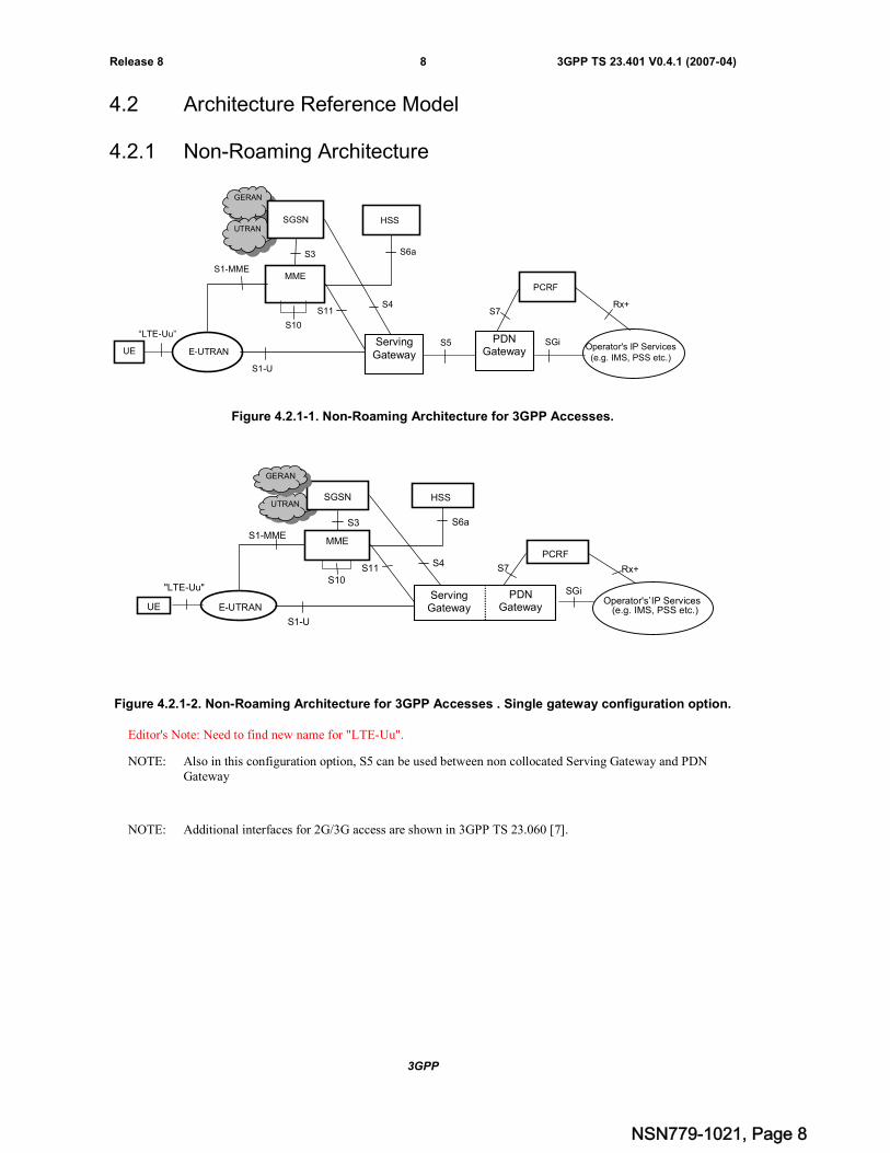
4.2 Architecture Reference Model
4.2.1 Non-Roaming Architecture
Figure 4.2.1-1. Non-Roaming Architecture for 3GPP Accesses.
Figure 4.2.1-2. Non-Roaming Architecture for 3GPP Accesses . Single gateway configuration option.
Editor's Note: Need to find new name for "LTE-Uu".
NOTE: Also in this configuration option, S5 can be used between non collocated Serving Gateway and PDNGateway
NOTE: Additional interfaces for 2G/3G access are shown in 3GPP TS 23.060 [7].
SGi
S4
S3
S1-MME
PCRF
S7
S6a
HSS
Operator's IP Services’(e.g. IMS, PSS etc.)
Rx+
UE
UTRANSGSN
"LTE-Uu"
E-UTRAN
MME
S11
S1-U
ServingGateway
PDNGateway
S10
GERAN
SGi
S4
S3
S1-MME
PCRF
S7
S6a
HSS
S10
UE
GERAN
UTRANSGSN
“LTE-Uu”
E-UTRAN
MME
S11
S5ServingGateway
PDNGateway
S1-U
Operator's IP Services(e.g. IMS, PSS etc.)
Rx+
NSN779-1021, Page 8

3GPP
3GPP TS 23.401 V0.4.1 (2007-04)9Release 8
4.2.2 Roaming Architecture
Figure 4.2.2-1. Roaming Architecture for 3GPP Accesses, Home Routed traffic.
Editor’s Note: Impact from Direct Tunnel architecture need to be included in the architecture diagrams.
Note: Additional interfaces/reference points for 2G/3G accesses are documented in 3GPP TS 23.060 [7].
Editor’s Note: the Roaming architecture for the Visited Services scenario and bearer traffic local breakout for theHome Services scenario needs to be included in this specification.
Editor’s Note: Following open issues exist for the above architecture diagram:
The roaming architecture for PCC is not included; as such the existence of S9 reference point betweenPCRF in the HPLMN and PCRF in the VPLMN is FFS.
4.3 High Level Functions
<This section explains the high level functions (eg charging, encryption) used in EPS>
4.3.1 General
The following list gives the logical functions performed within this system. Several functional groupings (metafunctions) are defined and each encompasses a number of individual functions:
- Network Access Control Functions.
- Packet Routeing and Transfer Functions.
- Mobility Management Functions.
- Radio Resource Management Functions.
- Network Management Functions.
S6a
HSS
S8a
S3
S1-MME
S10
GERAN
UTRANS
MME
S11
Ser
ingUE
“LTE-Uu”
E-UTRAN
S4
HPLMN
VPLMN
PCRF
S7 Rx+
SGi •Operator’s IPServices
(e.g. IMS, PSSetc.)
PDNGateway
S1-U
NSN779-1021, Page 9
3GPP
3GPP TS 23.401 V0.4.1 (2007-04)10Release 8
4.3.2 Network access control functions
4.3.2.1 General
Network access is the means by which a user is connected to the evolved packet core system.
4.3.2.2 Network/Access network selection
It is the means by which a UE selects a PLMN/Access network from which to gain IP connectivity.
4.3.2.3 Authentication and Authorisation Function
This function performs the identification and authentication of the service requester, and the validation of the servicerequest type to ensure that the user is authorised to use the particular network services. The authentication function isperformed in association with the Mobility Management functions.
4.3.2.4 Admission Control Function
<Text needs to be provided>
4.3.2.5 Policy and Charging Enforcement Function
This includes all the functionality of PCEF as defined by 3GPP TS 23.203 [6]. The PCEF encompasses service dataflow detection, policy enforcement and flow based charging functionalities as defined in 3GPP TS 23.203 [6].
4.3.2.6 Lawful Interception
<Text needs to be provided>
4.3.3 Packet routeing and transfer functions
4.3.3.1 General
A route is an ordered list of nodes used for the transfer of packets within and between the PLMN(s). Each route consistsof the originating node, zero or more relay nodes and the destination node. Routeing is the process of determining andusing, in accordance with a set of rules, the route for transmission of a message within and between the PLMN(s).
The EPS is an IP network and uses the standard routeing and transport mechanism of underlying IP network.
Editor's note: The above text does not appear to be relevant to a functional description.
4.3.3.2 IP Header Compression function
The compression function optimises use of radio capacity by IP header compression mechanisms.
4.3.3.3 Ciphering function
The ciphering function preserves the confidentiality of user data and signalling across the radio channels.
4.3.3.4 Integrity Protection function
<Text needs to be provided>
NSN779-1021, Page 10
3GPP
3GPP TS 23.401 V0.4.1 (2007-04)11Release 8
4.3.4 Mobility Management Functions
4.3.4.1 General
The mobility management functions are used to keep track of the current location of a UE.
4.3.4.2 Idle mode UE Tracking and Reachability Management
<Text needs to be provided>
4.3.4.3 Inter-eNB Mobility Anchor Function
<Text needs to be provided>
4.3.4.4 Inter-3GPP Mobility Anchor Function
<Text needs to be provided>
4.3.5 Radio Resource Management functions
Radio resource management functions are concerned with the allocation and maintenance of radio communicationpaths, and are performed by the radio access network. Refer to 3GPP TS 36.300 [5] for further information on E-UTRAN.
4.3.6 Network management functions
Network management functions provide mechanisms to support O&M functions related to the Evolved System.
The Network management architecture and functions for the evolved packet core system are described in 3GPP TSss.xyz[qq]
4.4 Network Elements
4.4.1 E-UTRAN
E-UTRAN is described in more detail in 3GPP TS 36.300 [5].
E-UTRAN functions include:
- Header compression and user plane ciphering
4.4.2 MME
MME functions include:
- NAS signalling
- NAS signalling security
- Inter CN node signalling for mobility between 3GPP access networks (terminating S3)
- Idle mode UE Tracking and Reachability (including control and execution of paging retransmission)
- Roaming (S6a towards home HSS)
- Authentication
NSN779-1021, Page 11

3GPP
3GPP TS 23.401 V0.4.1 (2007-04)12Release 8
- Bearer management functions including dedicated bearer establishment.
NOTE: The Serving GW and the MME may be implemented in one physical node or separated physical nodes.
4.4.3 Gateway
4.4.3.1 General
Two logical Gateways exist:
- Serving GW (S-GW)
- PDN GW (P-GW)
Functional split of PDN GW and Serving GW shall be the same regardless of the use of IETF or GTP based protocolsbetween them.
NOTE: The PDN GW and the Serving GW may be implemented in one physical node or separated physicalnodes.
4.4.3.2 Serving GW
The Serving GW is the gateway which terminates the interface towards E-UTRAN.
For each UE associated with the EPS, at a given point of time, there is a single Serving GW.
Serving GW functions include:
- the local Mobility Anchor point for inter-eNodeB handover
- Mobility anchoring for inter-3GPP mobility (terminating S4 and relaying the traffic between 2G/3G system andPDN GW)
- Lawful Interception
- Packet routing and forwarding
4.4.3.3 PDN GW
The PDN GW is the gateway which terminates the SGi interface towards the PDN.
If a UE is accessing multiple PDNs, there may be more than one PDN GW for that UE.
PDN GW functions include:
- Policy Enforcement
- Per-user based packet filtering (by e.g. deep packet inspection)
- Charging Support
- Lawful Interception
- UE IP address allocation
NSN779-1021, Page 12
3GPP
3GPP TS 23.401 V0.4.1 (2007-04)13Release 8
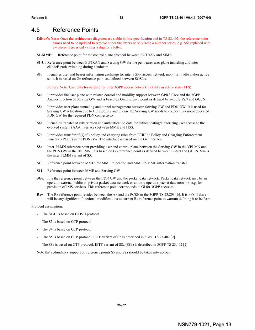
4.5 Reference Points
Editor’s Note: Once the architecture diagrams are stable in this specification and in TS 23.402, the reference pointnames need to be updated to remove either the letters or only keep a number series, e.g. S6a replaced withSn where there is only either a digit or a letter.
S1-MME: Reference point for the control plane protocol between EUTRAN and MME.
S1-U: Reference point between EUTRAN and Serving GW for the per bearer user plane tunneling and intereNodeB path switching during handover.
S3: It enables user and bearer information exchange for inter 3GPP access network mobility in idle and/or activestate. It is based on Gn reference point as defined between SGSNs.
Editor's Note: User data forwarding for inter 3GPP access network mobility in active state (FFS).
S4: It provides the user plane with related control and mobility support between GPRS Core and the 3GPPAnchor function of Serving GW and is based on Gn reference point as defined between SGSN and GGSN.
S5: It provides user plane tunneling and tunnel management between Serving GW and PDN GW. It is used forServing GW relocation due to UE mobility and in case the Serving GW needs to connect to a non-collocatedPDN GW for the required PDN connectivity.
S6a: It enables transfer of subscription and authentication data for authenticating/authorizing user access to theevolved system (AAA interface) between MME and HSS.
S7: It provides transfer of (QoS) policy and charging rules from PCRF to Policy and Charging EnforcementFunction (PCEF) in the PDN GW. The interface is based on the Gx interface.
S8a: Inter-PLMN reference point providing user and control plane between the Serving GW in the VPLMN andthe PDN GW in the HPLMN. It is based on Gp reference point as defined between SGSN and GGSN. S8a isthe inter PLMN variant of S5.
S10: Reference point between MMEs for MME relocation and MME to MME information transfer.
S11: Reference point between MME and Serving GW
SGi: It is the reference point between the PDN GW and the packet data network. Packet data network may be anoperator external public or private packet data network or an intra operator packet data network, e.g. forprovision of IMS services. This reference point corresponds to Gi for 3GPP accesses.
Rx+ The Rx reference point resides between the AF and the PCRF in the 3GPP TS 23.203 [6]. It is FFS if therewill be any significant functional modifications to current Rx reference point to warrant defining it to be Rx+.
Protocol assumption:
- The S1-U is based on GTP-U protocol.
- The S3 is based on GTP protocol.
- The S4 is based on GTP protocol.
- The S5 is based on GTP protocol. IETF variant of S5 is described in 3GPP TS 23.402 [2].
- The S8a is based on GTP protocol. IETF variant of S8a (S8b) is described in 3GPP TS 23.402 [2]
Note that redundancy support on reference points S5 and S8a should be taken into account.
NSN779-1021, Page 13

3GPP
3GPP TS 23.401 V0.4.1 (2007-04)14Release 8
4.6 Overall QoS Concept
4.6.1 The EPS Bearer
4.6.1.1 The EPS Bearer in general
An EPS bearer is a logical aggregate of one or more Service Data Flows (SDFs), defined in 3GPP TS 23.203[6],running between a UE and a PDN GW. An EPS bearer is the level of granularity for bearer level QoS control in theEPC/E-UTRAN. That is, SDFs mapped to the same EPS bearer receive the same bearer level packet forwardingtreatment (e.g. scheduling policy, queue management policy, rate shaping policy, RLC configuration, etc.). Providingdifferent bearer level QoS to two SDFs thus requires that a separate EPS bearer is established for each SDF.
NOTE: In addition but independent to bearer level QoS control, the PCC framework allows an optionalenforcement of service level QoS control on the granularity of SDFs independent of the binding of SDFsto EPS bearers.
An UpLink Traffic Flow Template (UL TFT) is a set of uplink packet filters. A DownLink Traffic Flow Template (DLTFT) is a set of downlink packet filters.
Editor's Note: Need to clarify the definitions of UL TFT and DL TFT and their relation to the terms 'TFT' and'service data flow template' as defined in 3GPP TS 23.060 and 3GPP TS 23.203, respectively.
An EPS bearer is referred to as a dedicated bearer if it is associated with an UL TFT in the UE and a DL TFT in thePDN GW where the filters only match certain packets. An EPS bearer is referred to as a default bearer if it is associatedwith "match all" uplink and downlink packet filters in the UE and the PDN GW, respectively.
An EPS bearer is referred to as a GBR bearer if dedicated network resources related to a Guaranteed Bit Rate (GBR)value that is associated with the EPS bearer are permanently allocated (e.g. by an admission control function in theeNodeB) at bearer establishment/modification. Otherwise, an EPS bearer is referred to as a Non-GBR bearer.
NOTE: Admission control can be performed at establishment / modification of a Non-GBR bearer even though aNon-GBR bearer is not associated with a GBR value.
A dedicated bearer can either be a GBR or a Non-GBR bearer. A default bearer shall be a Non-GBR bearer.
4.6.1.2 The EPS Bearer with GTP-based S5/S8
Figure 4.6-1. Two Unicast EPS bearers (GTP-u Based S5/S8).
An EPS bearer is realized by the following elements:
An UL TFT in the UE binds an SDF to an EPS bearer in the uplink direction. Multiple SDFs can bemultiplexed onto the same EPS bearer by including multiple uplink packet filters in the UL TFT.
PDN SAE GWeNB
S5/S8 Bearer
UL Service Data Flows DL Service Data Flows
DL TFT S5/S8a TEID
S1 Bearer
Serving GW PDN GWeNodeBUE
Radio Bearer
Application / Service Layer
UL TFT RBID
DL TFT
RBID S1-TEID S1-TEID S5/S8a TEID
NSN779-1021, Page 14
3GPP
3GPP TS 23.401 V0.4.1 (2007-04)15Release 8
A DL TFT in the PDN GW binds an SDF to an EPS bearer in the downlink direction. Multiple SDFs can bemultiplexed onto the same EPS bearer by including multiple downlink packet filters in the DL TFT.
A radio bearer (RLC connection) transports the packets of an EPS bearer between a UE and an eNodeB. Thereis a one-to-one mapping between an EPS bearer and a radio bearer.
An S1 bearer (GTP-u tunnel) transports the packets of an EPS bearer between an eNodeB and a Serving GW.
An S5/S8 bearer transports the packets of an EPS bearer between a Serving GW and a PDN GW.
A UE stores a mapping between an uplink packet filter and a radio bearer identifier (UL TFT RBID) tocreate the binding between an SDF and a radio bearer in the uplink.
In case S5/S8 is based on GTP-u, a PDN GW stores a mapping between a downlink packet filter and an S5/S8aGTP-u tunnel end-point identifier (DL TFT S5/S8a-TEID) to create the binding between an SDF and anS5/S8a bearer in the downlink.
An eNodeB stores a one-to-one mapping between a radio bearer identifier and an S1 GTP-u tunnel end-pointidentifier (RBID S1-TEID) to create the binding between a radio bearer and an S1 bearer.
In case S5/S8 is based on GTP-u, a Serving GW stores a one-to-one mapping between an S1 GTP-u tunnelend-point identifier and an S5/S8a GTP-u tunnel end-point identifier (S1-TEID S5/S8a-TEID) to create thebinding between an S1 bearer and an S5/S8a bearer.
4.6.1.3 The EPS Bearer with IETF-based S5/S8
<to be written>
4.6.2 Bearer level QoS parameters
Each EPS bearer (GBR and Non-GBR) is associated with the following bearer level QoS parameters.
Label
Allocation and Retention Priority (ARP)
A Label is a scalar that is used as a reference to access node-specific parameters that control bearer level packetforwarding treatment (e.g. scheduling weights, admission thresholds, queue management thresholds, link layer protocolconfiguration, etc.), and that have been pre-configured by the operator owning the access node (e.g. eNodeB). A one-to-one mapping of standardized Label values to standardized Label Characteristics (see clause 4.6.3) will be captured in a3GPP specification.
Editor's Note: Need to add this to the "3GPP specification" and create formal reference.
Editor's Note: The relationship between Label signalled on S1-MME, QCI signalled on S7, QoS profile signalled onS4 and QoS information signalled towards non-3GPP accesses needs to be clarified.
NOTE: On the radio interface and on S1, each PDU (e.g. RLC PDU or GTP-u PDU) is indirectly associated withone Label via the bearer identifier carried in the PDU header. The same applies to the S5 and S8interfaces in case they are based on GTP-u.
The primary purpose of ARP is to decide whether a bearer establishment / modification request can be accepted orneeds to be rejected in case of resource limitations (typically available radio capacity in case of GBR bearers). Inaddition, the ARP can be used (e.g. by the eNodeB) to decide which bearer(s) to drop during exceptional resourcelimitations (e.g. at handover). Once successfully established, a bearer's ARP shall not have any impact on the bearerlevel packet forwarding treatment (e.g. scheduling and rate control). Such packet forwarding treatment should be solelydetermined by the other bearer level QoS parameters: Label, GBR, MBR, and AMBR.
NOTE: The ARP should be understood as "Priority of Allocation and Retention"; not as "Allocation, Retention,and Priority". A more precise definition of ARP, e.g. the encoding of 'retention', is left FFS.
NSN779-1021, Page 15

3GPP
3GPP TS 23.401 V0.4.1 (2007-04)16Release 8
Each GBR bearer is additionally associated with the following bearer level QoS parameters.
Guaranteed Bit Rate (GBR)
Maximum Bit Rate (MBR)
The GBR denotes the bit rate that can be expected to be provided by a GBR bearer. The MBR limits the bit rate thatcan be expected to be provided by a GBR bearer (e.g. excess traffic may get discarded by a rate shaping function). TheMBR may be greater than or equal to GBR for a particular GBR bearer.
Editor's note: Whether a Non-GBR bearer may also be associated with an MBR is FFS.
Editor's note: Rate-adaptation schemes are FFS.
Each UE is associated with the following bearer level QoS parameter.
Aggregate Maximum Bit Rate (AMBR)
Multiple EPS bearers of the same UE can share the same AMBR. That is, each of those EPS bearers could potentiallyutilize the entire AMBR, e.g. when the other EPS bearers do not carry any traffic. The AMBR limits the aggregate bitrate that can be expected to be provided by the EPS bearers sharing the AMBR (e.g. excess traffic may get discarded bya rate shaping function). AMBR applies to all Non-GBR bearers of a UE. GBR bearers are outside the scope of AMBR.
Editor's note: Further details related to the scope and the signalling of AMBR are FFS.
The GBR and MBR denote bit rates of traffic per bearer while AMBR denotes a bit rate of traffic per group of bearers.Each of those three bearer level QoS parameters has an uplink and a downlink component. On S1_MME the values ofthe GBR, MBR, and AMBR refer to the bit stream excluding the GTP-u header overhead on S1_U.
Editor's note: A more precise definition of GBR, MBR, and AMBR, e.g. whether those parameters only denote a bitrate or additionally also a token bucket size, is left FFS.
4.6.3 Standardized Label Characteristics
A Label Characteristic describes the bearer level packet forwarding treatment that is expected from an access node (e.g.eNodeB). A standardized Label Characteristic comprises the following elements:
1 Bearer Type (GBR or Non-GBR),
2 L2 Packet Delay Budget, and
3 L2 Packet Loss Rate.
A Label Characteristic is not signaled on any interface.
The Bearer Type determines if dedicated network resources related to a Guaranteed Bit Rate (GBR) value that isassociated with an EPS bearer are permanently allocated (e.g. by an admission control function in the access node) atbearer establishment/modification (see clause 4.6.1).
The L2 Packet Delay Budget (L2 PDB) denotes the time that a link layer SDU (e.g., an IP packet) may reside withinthe link layer between an access node and a UE. The link layer may include a queue management function. For a certainLabel Characteristic the value of the L2 PDB is the same in uplink and downlink. The purpose of the L2 PDB is tosupport the configuration of scheduling and link layer functions (e.g. the setting of scheduling priority weights andHARQ target operating points).
NOTE: For Non-GBR bearers, the L2 PDB denotes a "soft upper bound" in the sense that an "expired" link layerSDU, i.e. a link layer SDU that has exceeded the L2 PDB, does not need to be discarded (e.g. by RLC inE-UTRAN). The discarding (dropping) of packets is expected to be controlled by a queue managementfunction, e.g. based on pre-configured dropping thresholds.
Sources running on a Non-GBR bearer should be prepared to experience congestion related packet drops and/or perpacket delays that may exceed a given L2 PDB. This may for example occur during traffic load peaks or when the UEbecomes coverage limited. See Annex B for details.
NSN779-1021, Page 16
3GPP
3GPP TS 23.401 V0.4.1 (2007-04)17Release 8
Sources running on a GBR bearer and sending at a rate smaller than or equal to GBR can in general assume thatcongestion related packet drops will not occur, and that per packet delays will not exceed a given L2 PDB. Exceptions(e.g. transient link outages) can always occur in a radio access system. The fraction of traffic sent on a GBR bearer at arate greater than GBR may be treated like traffic on a Non-GBR bearer.
Editor's note: The handling of codecs such as AMR on GBR bearers with MBR>GBR needs to be studied further.
The L2 Packet Loss Rate (L2 PLR) determines the rate of SDUs (e.g. IP packets) that have been processed by thesender of a link layer ARQ protocol (e.g. RLC in E-UTRAN) but that are not successfully delivered by thecorresponding receiver to the upper layer (e.g. PDCP in E-UTRAN). Thus, the L2 PLR denotes a rate of non congestionrelated packet losses. The purpose of the L2 PLR is to allow for appropriate link layer protocol configurations (e.g.RLC and HARQ in E-UTRAN). For a certain Label Characteristic the value of the L2 PLR is the same in uplink anddownlink.
5 Functional Description and Information FlowsEditor's note: The principles of option B for MME separation (see annex H of 23.882) shall be used.
5.1 Control and User Planes
<This section specifies the protocol stacks on the control and user planes for each of the interfaces.>
5.2 Identities
< This section gives a high level overview of the identities used in EPC/E-UTRAN and their usage. The exactdefinitions will be in 23.003.>
5.3 Authentication, Security and Location Management
<This section describes the MM functionality and signalling flows for, eg attach, detach, identity check, paging,gateway selection, IP address allocation etc.>
5.3.1 IP Address allocation
One of the following ways shall be used to allocate IP addresses for the UE:
a) The HPLMN allocates the IP address to the UE when the default bearer is activated (dynamic HPLMN address);
b) The VPLMN allocates the IP address to the UE when the default bearer is activated (dynamic VPLMN address);or
c) The PDN operator or administrator allocates an IP address to the UE when the default bearer is activated(External PDN Address Allocation).
Editor's Note: It is FFS whether permanent (static) IP address allocation by the HPLMN will be supported in EPS.
The IP address allocated for the UE's default bearer shall also be used for the UE's dedicated bearers towards the samePDN. The IP address allocation for the multiple PDN GW case is FFS.
It is the HPLMN operator that shall define in the subscription whether a dynamic HPLMN or VPLMN address may beused.
NSN779-1021, Page 17
3GPP
3GPP TS 23.401 V0.4.1 (2007-04)18Release 8
5.3.2 Attach procedure
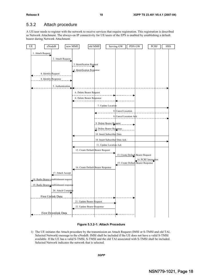
A UE/user needs to register with the network to receive services that require registration. This registration is describedas Network Attachment. The always-on IP connectivity for UE/users of the EPS is enabled by establishing a defaultbearer during Network Attachment.
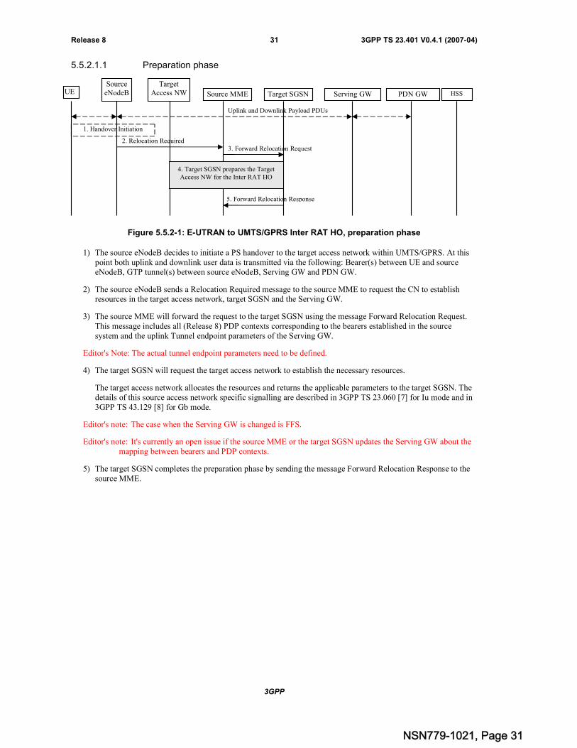
Figure 5.3.2-1: Attach Procedure
1) The UE initiates the Attach procedure by the transmission an Attach Request (IMSI or S-TMSI and old TAI,Selected Network) message to the eNodeB. IMSI shall be included if the UE does not have a valid S-TMSIavailable. If the UE has a valid S-TMSI, S-TMSI and the old TAI associated with S-TMSI shall be included.Selected Network indicates the network that is selected.
3. Identification Request
1. Attach Request
new MME old MME Serving GW PCRF HSS
3. Identification Response
PDN GW
2. Attach Request
eNodeBUE
4. Identity Request
4. Identity Response
16. Create Default Bearer Response
12. Create Default Bearer Request
5. Authentication
7. Update Location
8. Cancel Location
11. Update Location Ack
8. Cancel Location Ack
9. Delete Bearer Request
9. Delete Bearer Response
17. Attach Accept
First Uplink Data
13. Create Default Bearer Request
15. Create Default Bearer Response
6. Delete Bearer Response
6. Delete Bearer Request
10. Insert Subscriber Data
10. Insert Subscriber Data Ack.
14. PCRF Interaction
19. Radio Bearer establishment response
18. Radio Bearer establishment request
20. Attach Complete
22. Update Bearer Response
21. Update Bearer Request
First Downlink Data
NSN779-1021, Page 18
3GPP
3GPP TS 23.401 V0.4.1 (2007-04)19Release 8
Editor's note: It's FFS whether the APN information is provided by the UE.
2) The eNodeB derives the MME from the S-TMSI and from the indicated Selected Network. If no MME can bederived the eNodeB selects an MME as described in clause "MME selection function". The eNodeB forwardsthe Attach Request message together with an indication of the Cell Global Identity of the cell from where itreceived the message to the new MME.
Editor's note: It's FFS whether the eNodeB will provide the TEID to the MME in this step.
3) If the UE identifies itself with S-TMSI and the MME has changed since detach, the new MME sends anIdentification Request (S-TMSI, old TAI) to the old MME to request the IMSI. The old MME responds withIdentification Response (IMSI, Authentication Quintets). If the UE is not known in the old MME, the old MMEresponds with an appropriate error cause.
4) If the UE is unknown in both the old and new MME, the MME sends an Identity Request to the UE to requestthe IMSI. The UE responds with Identity Response (IMSI).
5) If no UE context for the UE exists anywhere in the network, authentication is mandatory. The authenticationfunctions are defined in clause x.x.
6) If there are active bearer contexts in the new MME for this particular UE (i.e. the UE re-attaches to the sameMME without having properly detached before), the new MME deletes these bearer contexts by sending DeleteBearer Request messages to the GWs involved. The GWs acknowledge with Delete Bearer Response message.
Editor's note: The concept of bearer context needs to be defined.
7) If the MME has changed since the last detach, or if it is the very first attach, the MME sends an Update Location(MME Identity, IMSI) to the HSS.
8) The HSS sends Cancel Location (IMSI, Cancellation Type) to the old MME with Cancellation Type set toUpdate Procedure. The old MME acknowledges with Cancel Location Ack (IMSI) and removes the MM andbearer contexts.
9) If there are active bearer contexts in the old MME for this particular UE, the old MME deletes these bearercontexts by sending Delete Bearer Request messages to the GWs involved. The GWs return Delete BearerResponse message to the MME.
Editor's note: It's FFS which flow triggers the Delete Bearer Request messages.
10)The HSS sends Insert Subscriber Data (IMSI, Subscription Data) message to the new MME. The new MMEvalidates the UE's presence in the (new) TA. If due to regional subscription restrictions or access restrictions theUE is not allowed to attach in the TA, the MME rejects the Attach Request with an appropriate cause, and mayreturn an Insert Subscriber Data Ack message to the HSS. If subscription checking fails for other reasons, theMME rejects the Attach Request with an appropriate cause and returns an Insert Subscriber Data Ack message tothe HSS including an error cause. If all checks are successful then the MME constructs a context for the UE andreturns an Insert Subscriber Data Ack message to the HSS.
11)The HSS acknowledges the Update Location message by sending an Update Location Ack to the MME. If theUpdate Location is rejected by the HSS, the MME rejects the Attach Request from the UE with an appropriatecause.
Editor's note: further considerations on subscription data handling needed, e.g. if transferred between MMEs, ifinsertion by separated procedure from HSS necessary or if Steps 9 and 10 can be combined as onemessage.
12)The MME selects a Serving GW as described under "GW Selection Function" and sends a Create Default BearerRequest (IMSI, MME Context ID) message to the selected Serving GW.
13)The Serving GW creates a new entry in its EPS Bearer table and sends a Create Default Bearer Request (ServingGW Address for the user plane, Serving GW TEID of the user plane, Serving GW TEID of the control plane)message to the PDN GW.
Editor’s Note: It's FFS which entity will select the PDN GW.
Editor’s Note: This step is for GTP based S5/S8 reference point, it's FFS for IETF based S5/S8 reference point.
NSN779-1021, Page 19

3GPP
3GPP TS 23.401 V0.4.1 (2007-04)20Release 8
14)The PDN GW may interact with the PCRF to get the default PCC rules for the UE In case PCRF is applied in thenetwork.
Editor's note: It is FFS which kind of information will be provided by the PCRF.
15)The PDN GW returns a Create Default Bearer Response (PDN GW Address for the user plane, PDN GW TEIDof the user plane, PDN GW TEID of the control plane, PDN Address) message to the Serving GW. PDNAddress is included if the PDN GW allocated a PDN address.
Editor’s Note: This step is for GTP based S5/S8 reference point, it's FFS for IETF based S5/S8 reference point.
16)The Serving GW returns a Create Default Bearer Response (PDN Address, Serving GW address for User Plane,Serving GW TEID for User Plane, Serving GW Context ID) message to the MME.
17)The MME sends an Attach Accept (S-TMSI, PDN address, TA List) message to the eNodeB. S-TMSI isincluded if the MME allocates a new S-TMSI. This message is contained in an S1_MME control message InitialContext Setup Request. This S1 control message also includes the security context for the UE and QoSinformation needed to set up the radio bearer, as well as the TEID at the Serving GW used for user plane and theaddress of the Serving GW for user plane. The PDN address assigned to the UE is included in this message.
18)The eNodeB sends Radio Bearer Establishment Request to the UE and the Attach Accept Message (S-TMSI,PDN address, TA List) will be sent along to the UE.
19)The UE sends the Radio Bearer Establishment Response (FFS) to the eNodeB. In this message, the AttachComplete Message will be included.
20)The eNodeB will forward the Attach Complete message to the MME. On the S1_MME reference point, thismessage is contained in an S1_MME control message Initial Context Setup Complete. This S1 control messagealso includes the TEID of the eNodeB and the address of the eNodeB used for downlink traffic on the S1_Ureference point.
After the Attach Accept message, the UE can then send uplink packets towards the eNodeB which will then betunnelled to the Serving GW and PDN GW.
21)The MME sends an Update Bearer Request (eNodeB address, eNodeB TEID) message to the Serving GW.
22)The Serving GW acknowledges by sending Update Bearer Response to the MME. The Serving GW can thensend its buffered downlink packets.
NOTE: After Step 13, the PDN GW may assign the PDN address to the UE or leave the PDN address unassigned.In some cases (e.g. non-integrated devices, such as Laptop), the UE PDN address may need to beassigned after the completion of attach procedure (e.g. via DHCP).
Editor's Note: It's FFS how the EPS knows which type of PDN address to use.
NSN779-1021, Page 20

3GPP
3GPP TS 23.401 V0.4.1 (2007-04)21Release 8
5.3.3 Tracking Area Update procedures
5.3.3.1 Tracking Area Update procedure with MME and Serving GW change
Figure 5.3.3-1: Tracking Area Update procedure with MME and Serving GW change
1) The UE detects a change to a new TA by discovering that its current TA is not in the list of TAs that the UEregistered with the network.
2) The UE initiates the TAU procedure by sending a TAU Request (S-TMSI and old TAI, Selected Network)message to the eNodeB. The S-TMSI and the old TAI associated with S-TMSI shall be included. SelectedNetwork indicates the network that is selected.
Editor's note: FFS whether to add an indication to the message that allows the UE to request to establish the userplane on radio and S1 as part of the TAU procedure
3) The eNodeB derives the MME from the S-TMSI and from the indicated Selected Network. If no MME can bederived the eNodeB selects an MME.
Editor's note: MME selection function needs to be resolved.
The eNodeB forwards the TAU Request message together with an indication of the Cell Global Identity of thecell from where it received the message to the new MME.
4) The new MME sends an MME Context Request (S-TMSI, old TAI) to the old MME to retrieve user information.The new MME derives the old MME from old TAI and old S-TMSI.
FFS whether TAU Request message needs to be forwarded to old MME, e.g. to perform integrity check of themessage in case this cannot be done by the new MME. An alternative may be using an S-TMSI signature.
4. MME Context Request
11. Create Bearer Response
2. TAU Request
new MME old MMEnew Serving
GWPDN GW
HSS
1. UE changes to a newTracking Area
8. Create Bearer Request
5. MME Context Response
6. Authentication
12. Update Location
13. Cancel Location
15. Update Location Ack
14. Cancel Location Ack
16. Delete Bearer Request
17. Delete Bearer Response
18. TAU Accept
19. TAU Complete
9. Update Bearer Request
10. Update Bearer Response
7. MME Context Acknowledge
old ServingGW
3. TAU Request
eNodeBUE
NSN779-1021, Page 21

3GPP
3GPP TS 23.401 V0.4.1 (2007-04)22Release 8
5) The old MME responds with an MME Context Response (MME context (e.g. IMSI, Authentication Quintets,bearer contexts)). If the UE is not known in the old MME, the old MME responds with an appropriate errorcause.
Editor's note: It is FFS whether MME stores all bearer context parameters including PDN GW address or whether itneeds to ask the Serving GW
6) The authentication functions are defined in the clause "Security Function". Ciphering procedures are described inclause "Security Function". If S-TMSI allocation is going to be done and the network supports ciphering, theNAS messages shall be ciphered.
7) The new MME sends an MME Context Acknowledge message to the old MME. The old MME marks in itscontext that the information in the GWs and the HSS are invalid. This ensures that the old MME updates theGWs and the HSS if the UE initiates a TAU procedure back to the old MME before completing the ongoingTAU procedure. If the security functions do not authenticate the UE correctly, then the TAU shall be rejected,and the new MME shall send a reject indication to the old MME. The old MME shall continue as if theIdentification and Context Request was never received.
8) The new MME validates the UE's presence in the (new) TA. If due to regional subscription restrictions or accessrestrictions the UE is not allowed to attach in the TA, the MME rejects the TAU Request with an appropriatecause. If subscription checking fails for other reasons, the MME rejects the TAU Request with an appropriatecause. If all checks are successful then the MME constructs an MM context for the UE.
The new MME verifies whether the old Serving GW can continue to serve the UE. If not it selects a new ServingGW as described under "GW selection function" and sends a Create Bearer Request (IMSI, bearer contexts,MME Context ID) message to the selected new Serving GW. The PDN GW address is indicated in the bearerContexts.
9) The new Serving GW sends Update Bearer Request message (Serving GW Address, Serving GW TunnelEndpoint Identifier) to the PDN GW concerned.
Editor's note: steps 9 and 10 are specific for the GTP based option of S5/S8
10)The PDN GW updates its bearer contexts and returns an Update Bearer Response (PDN GW TEID) message.
11)The Serving GW updates its bearer context. This allows the Serving GW to route Bearer PDUs to the PDN GWwhen received from eNodeB.
The Serving GW returns a Create Bearer Response (MME Context ID, Serving GW address and TEID for userplane, Serving GW Context ID) message to the new MME.
12)The new MME sends an Update Location (MME Identity, IMSI) to the HSS.
13)The HSS sends Cancel Location (IMSI, Cancellation Type) to the old MME with Cancellation Type set toUpdate Procedure.
14)The old MME acknowledges with Cancel Location Ack (IMSI).
15)The HSS acknowledges the Update Location (Subscription Data) message by sending an Update Location Ackmessage to the MME after the cancelling of old MM context is finished. If the Update Location is rejected by theHSS, the MME rejects the TAU Request from the UE with an appropriate cause.
Editor's note: further considerations on subscription data handling needed, e.g. if transferred between MMEs, ifinserted by separated procedure from HSS or combined with Update Location procedure
16)If there are active bearers in the old MME for this particular UE and the new MME has indicated that ServingGW functionality is to be moved, the old MME deletes these bearers by sending Delete Bearer Request (TEID)messages to the Serving GW.
Editor's note: it is FFS when this step is triggered, e.g. by step 7 (by an indication from new to old MME that oldMME can release the Serving GW) or by step 13
17)The Serving GW acknowledges with Delete Bearer Response (TEID) messages.
18)The MME sends a TAU Accept (S-TMSI, TA list) message to the UE. S-TMSI is included if the MME allocatesa new S-TMSI.
NSN779-1021, Page 22

3GPP
3GPP TS 23.401 V0.4.1 (2007-04)23Release 8
19)If S-TMSI was changed, the UE acknowledges the received S-TMSI by returning a TAU Complete message tothe MME.
5.3.4 Service Request procedures
5.3.4.1 UE triggered Service Request
Figure 5.3.4-1. UE triggered Service Request procedure
1) The UE sends NAS message Service Request (S-TMSI, TAI, Service Type) towards the MME encapsulated inan RRC message to the eNodeB. The RRC message(s) that can be used to carry this NAS message are describedin 3GPP TS 36.300 [5].
2) The eNodeB forwards NAS message to MME. NAS message is encapsulated in an S1-AP: Initial UE Message(NAS message, Cell Global ID of the serving cell). Details of this step are described in 3GPP TS 36.300 [5].
Whether TEID(s) of eNodeB could be allocated already in this step is FFS.
3) NAS authentication procedures may be performed.
4) The MME sends S1-AP Initial Context Setup Request (Serving GW address, S1-TEID(s) (UL), Bearer QoS(s),Security Context, MME Signalling Connection Id) message to the eNodeB. This step activates the radio and S1bearers for the default bearer and the pre-established dedicated bearers. The need for a mechanism to activateonly a subset of the existing EPS bearers is FFS. The eNodeB stores the Security Context, MME SignallingConnection Id, Bearer QoS profile(s) and S1-TEID(s) in the UE RAN context. The step is described in detail in3GPP TS 36.300 [5].
5) The eNodeB performs the radio bearer establishment procedure. The user plane security mode is established atthis step. This step implicitly confirms the Service Request. This step is described in detail in 3GPP TS 36.300[5].
6) The uplink data from the UE can now be forwarded by eNodeB to the Serving GW. The eNodeB sends theuplink data to the Serving GW address and TEID provided in the step 4.
It is FFS if the uplink data can be forwarded onwards by Serving GW only after step 8.
MME Serving GW PDN GW
2. NAS: Service Request
1. NAS: Service Request
7. S1-AP: Initial Context Setup Complete
3. Authentication
HSS
4. S1-AP: Initial Context Setup Request
5. Radio Bearer Establishment
6. Uplink Data
8. Update Bearer Request
9. Update Bearer Response
UE eNodeB
NSN779-1021, Page 23
3GPP
3GPP TS 23.401 V0.4.1 (2007-04)24Release 8
7) The eNodeB sends an S1-AP message Initial Context Setup Complete (eNodeB address, S1 TEID(s) (DL)) to theMME. This step is described in detail in 3GPP TS 36.300 [5].
8) The MME sends an Update Bearer Request message (eNodeB address, S1 TEID(s) (DL)) to the Serving GW.The Serving GW is now able to transmit downlink data towards the UE.
9) The Serving GW sends an Update Bearer Response to the MME.
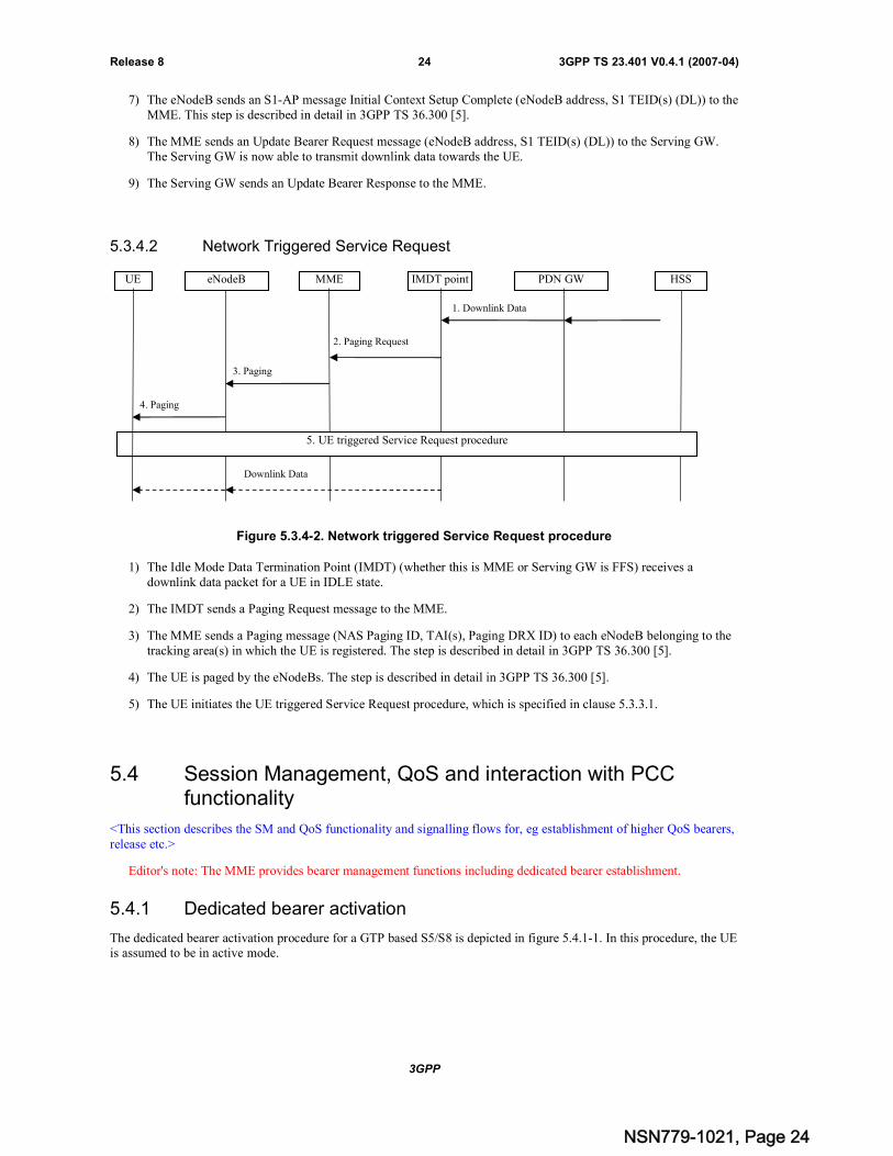
5.3.4.2 Network Triggered Service Request
Figure 5.3.4-2. Network triggered Service Request procedure
1) The Idle Mode Data Termination Point (IMDT) (whether this is MME or Serving GW is FFS) receives adownlink data packet for a UE in IDLE state.
2) The IMDT sends a Paging Request message to the MME.
3) The MME sends a Paging message (NAS Paging ID, TAI(s), Paging DRX ID) to each eNodeB belonging to thetracking area(s) in which the UE is registered. The step is described in detail in 3GPP TS 36.300 [5].
4) The UE is paged by the eNodeBs. The step is described in detail in 3GPP TS 36.300 [5].
5) The UE initiates the UE triggered Service Request procedure, which is specified in clause 5.3.3.1.
5.4 Session Management, QoS and interaction with PCCfunctionality
<This section describes the SM and QoS functionality and signalling flows for, eg establishment of higher QoS bearers,release etc.>
Editor's note: The MME provides bearer management functions including dedicated bearer establishment.
5.4.1 Dedicated bearer activation
The dedicated bearer activation procedure for a GTP based S5/S8 is depicted in figure 5.4.1-1. In this procedure, the UEis assumed to be in active mode.
1. Downlink Data
2. Paging Request
MME IMDT point PDN GW
3. Paging
4. Paging
HSS
5. UE triggered Service Request procedure
Downlink Data
UE eNodeB
NSN779-1021, Page 24

3GPP
3GPP TS 23.401 V0.4.1 (2007-04)25Release 8
Figure 5.4.1-1. Dedicated Bearer Activation Procedure, UE in Active Mode
NOTE: Steps 3-8 are common for architecture variants with GTP based S5/S8 and IETF based S5/S8. For anIETF based S5/S8, steps 1, 2, 9 and 10 are FFS.
1) For GTP based S5/S8: Optionally, the PCRF sends a PCC decision provision (QoS policy) message to thePDN GW. If the PCC architecture is not present, the PDN GW may apply a local QoS policy.
2) For GTP based S5/S8: The PDN GW uses this QoS policy to assign the bearer QoS, i.e., it assigns the valuesto the bearer level QoS parameters (excluding AMBR); see clause 4.6.2. The PDN GW sends a CreateDedicated Bearer Request message (Bearer QoS, UL TFT, S5/S8 TEID) to the Serving GW.
Editor's note: The identifier(s) used for bearer identification and linking with the default bearer is FFS.
3) The Serving GW sends the Create Dedicated Bearer Request (Bearer QoS, UL TFT, S1-TEID) message tothe MME.
4) The MME builds a Session Management Configuration IE including the UL TFT. The MME then signals theBearer Setup Request (Bearer QoS, Session Management Configuration, S1-TEID) message to the eNodeB.
5) The eNodeB maps the bearer QoS to the Radio Bearer QoS. It then signals a Radio Bearer Setup Request(Radio Bearer QoS, Session Management Configuration) message to the UE. The UE uses the uplink packetfilter (UL TFT) to determine the mapping of service data flows to the radio bearer.
NOTE: The details of the Radio Bearer QoS are specified by RAN2.
6) The UE NAS layer builds a Session Management Response IE. The UE then acknowledges the radio beareractivation to the eNodeB with a Radio Bearer Setup Response (Session Management Response) message.
7) The eNodeB acknowledges the bearer activation to the MME with a Bearer Setup Response (S1-TEID,Session Management Response) message. The eNodeB indicates whether the requested Bearer QoS could beallocated or not.
8) The MME acknowledges the bearer activation to the Serving GW by sending a Create Dedicated BearerResponse (S1-TEID) message.
(1. PCC Decision Provision)
3. Create Dedicated Bearer Request
MME Serving GW PDN GW PCRF
4. Bearer Setup Request
5. Radio Bearer Setup Request
2. Create Dedicated Bearer Request
6. Radio Bearer Setup Response
7. Bearer Setup Response
8. Create Dedicated Bearer Response
9. Create Dedicated Bearer Response
(10. Provision Ack)
eNodeBUE
NSN779-1021, Page 25
3GPP
3GPP TS 23.401 V0.4.1 (2007-04)26Release 8
9) For GTP based S5/S8: The Serving GW acknowledges the bearer activation to the PDN GW by sending aCreate Dedicated Bearer Response (S5/S8-TEID) message.
10)For GTP based S5/S8: If the dedicated bearer activation procedure was triggered by a PCC DecisionProvision message from the PCRF, the PDN GW indicates to the PCRF whether the requested PCC decision(QoS policy) could be enforced or not by sending a Provision Ack message.
NOTE: The exact signalling of step 1 and 10 (e.g. in case of local break-out) is outside the scope of thisspecification. This signalling and its interaction with the dedicated bearer activation procedure are to bespecified in 3GPP TS 23.203 [x]. Steps 1 and 10 are included here only for completeness.
5.4.2 Dedicated bearer modification with bearer QoS update
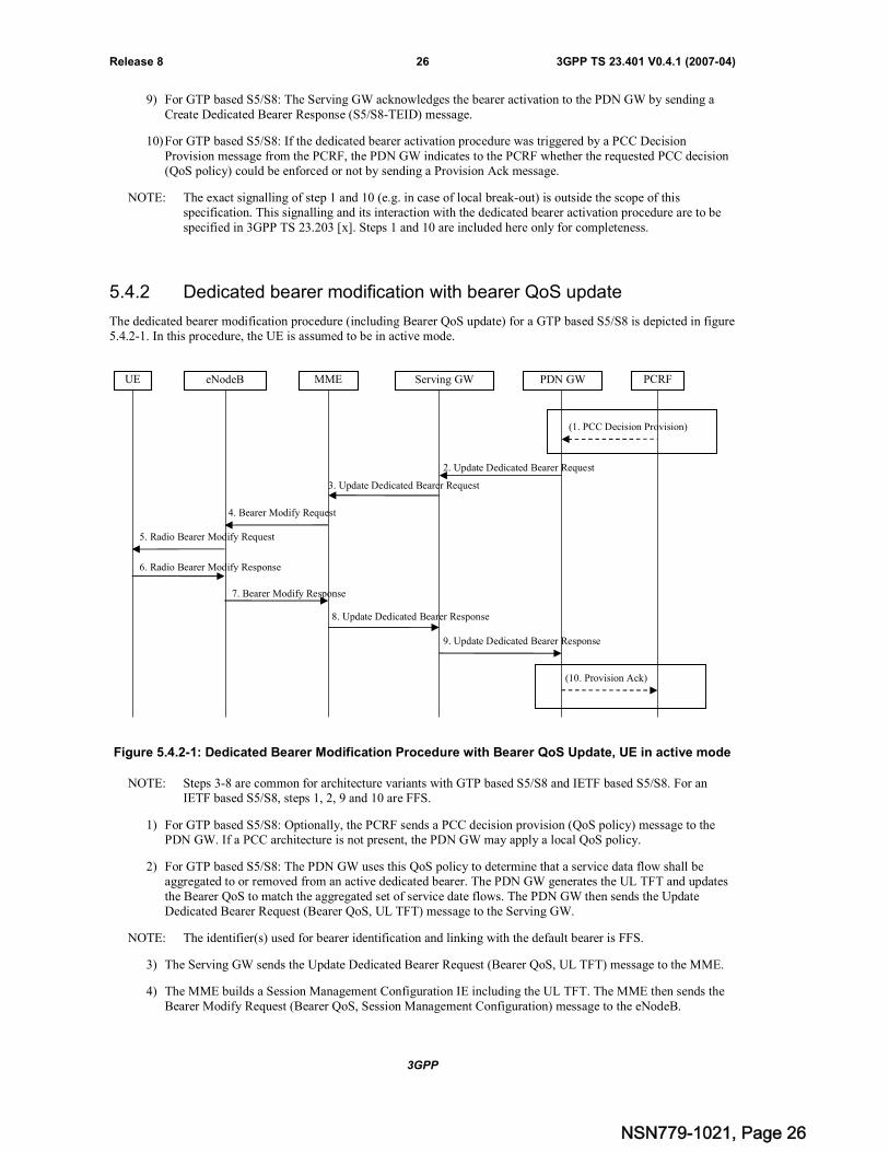
The dedicated bearer modification procedure (including Bearer QoS update) for a GTP based S5/S8 is depicted in figure5.4.2-1. In this procedure, the UE is assumed to be in active mode.
Figure 5.4.2-1: Dedicated Bearer Modification Procedure with Bearer QoS Update, UE in active mode
NOTE: Steps 3-8 are common for architecture variants with GTP based S5/S8 and IETF based S5/S8. For anIETF based S5/S8, steps 1, 2, 9 and 10 are FFS.
1) For GTP based S5/S8: Optionally, the PCRF sends a PCC decision provision (QoS policy) message to thePDN GW. If a PCC architecture is not present, the PDN GW may apply a local QoS policy.
2) For GTP based S5/S8: The PDN GW uses this QoS policy to determine that a service data flow shall beaggregated to or removed from an active dedicated bearer. The PDN GW generates the UL TFT and updatesthe Bearer QoS to match the aggregated set of service date flows. The PDN GW then sends the UpdateDedicated Bearer Request (Bearer QoS, UL TFT) message to the Serving GW.
NOTE: The identifier(s) used for bearer identification and linking with the default bearer is FFS.
3) The Serving GW sends the Update Dedicated Bearer Request (Bearer QoS, UL TFT) message to the MME.
4) The MME builds a Session Management Configuration IE including the UL TFT. The MME then sends theBearer Modify Request (Bearer QoS, Session Management Configuration) message to the eNodeB.
(1. PCC Decision Provision)
3. Update Dedicated Bearer Request
MME Serving GW PDN GW PCRF
4. Bearer Modify Request
5. Radio Bearer Modify Request
2. Update Dedicated Bearer Request
6. Radio Bearer Modify Response
7. Bearer Modify Response
8. Update Dedicated Bearer Response
9. Update Dedicated Bearer Response
(10. Provision Ack)
UE eNodeB
NSN779-1021, Page 26

3GPP
3GPP TS 23.401 V0.4.1 (2007-04)27Release 8
5) The eNodeB maps the modified Bearer QoS to the Radio Bearer QoS. It then signals a Radio Bearer ModifyRequest (Radio Bearer QoS, Session Management Configuration) message to the UE. The UE uses theuplink packet filter (UL TFT) to determine the mapping of service data flows to the radio bearer.
NOTE: The details of the Radio Bearer QoS are specified by RAN2.
6) The UE NAS layer builds a Session Management Response IE. The UE then acknowledges the radio bearermodification to the eNodeB with a Radio Bearer Modify Response (Session ManagementResponse).message.
7) The eNodeB acknowledges the bearer modification to the MME with a Bearer Modify Response (SessionManagement Response) message. With this message, the eNodeB indicates whether the requested BearerQoS could be allocated or not.
8) The MME acknowledges the bearer modification to the Serving GW by sending an Update Dedicated BearerResponse message.
9) For GTP based S5/S8: The Serving GW acknowledges the bearer modification to the PDN GW by sendingan Update Dedicated Bearer Response message.
10)For GTP based S5/S8: If the dedicated Bearer modification procedure was triggered by a PCC DecisionProvision message from the PCRF, the PDN GW indicates to the PCRF whether the requested PCC decision(QoS policy) could be enforced or not by sending a Provision Ack message.
NOTE: The exact signalling of step 1 and 10 (e.g. in case of local break-out) is outside the scope of thisspecification. This signalling and its interaction with the dedicated bearer activation procedure are to bespecified in 3GPP TS 23.203 [6]. Steps 1 and 10 are included here only for completeness.
5.4.3 Dedicated bearer modification without bearer QoS update
The bearer modification procedure without QoS update is used to update the UL TFT for an active dedicated bearer.This procedure for a GTP based S5/S8 is depicted in figure 5.4.3-1. In this procedure, the UE is assumed to be in activemode.
1. PCC Policy Provision
3. Update Dedicated Bearer Request
MME Serving GW PDN GW PCRF
4. Downlink NAS Transport
5. Direct Transfer
2. Update Dedicated Bearer Request
6. Direct Transfer
7. Uplink NAS Transport
8. Update Dedicated Bearer Response
9. Update Dedicated Bearer Response
10. Provision Ack
eNodeBUE
NSN779-1021, Page 27
3GPP
3GPP TS 23.401 V0.4.1 (2007-04)28Release 8
Figure 5.4.3-1: Dedicated Bearer Modification Procedure without Bearer QoS Update, UE in activemode
NOTE: Steps 3-8 are common for architecture variants with GTP based S5/S8 and IETF based S5/S8. For anIETF based S5/S8, steps 1,2,9 and 10 are FFS.
1) For GTP based S5/S8: Optionally, the PCRF sends a PCC decision provision (QoS policy) message to thePDN GW. If a PCC architecture is not present, the PDN GW may apply a local QoS policy.
2) For GTP based S5/S8: The PDN GW uses this QoS policy to determine that a service data flow shall beaggregated to or removed from an active dedicated bearer. The PDN GW generates the UL TFT anddetermines that no update of the Bearer QoS is needed. The PDN GW then sends the Update DedicatedBearer Request (UL TFT) message to the Serving GW.
Editor's note: The identifier(s) used for bearer identification and linking with the default bearer is FFS.
3) The Serving GW sends the Update Dedicated Bearer Request (UL TFT) message to the MME.
4) The MME builds a Session Management Configuration IE including the UL TFT. The MME then sends aDownlink NAS Transport (Session Management Configuration) message to the eNodeB.
5) The eNodeB sends the Direct Transfer (Session Management Configuration) message to the UE. The UEuses the uplink packet filter (UL TFT) to determine the mapping of service data flows to the radio bearer.
6) The UE NAS layer builds a Session Management Response. The UE then sends a Direct Transfer (SessionManagement Response) message to the eNodeB.
7) The eNodeB sends an Uplink NAS Transport (Session Management Response) message to the eNodeB.
8) The MME acknowledges the bearer modification to the Serving GW by sending an Update Dedicated BearerResponse message.
9) For GTP based S5/S8: The Serving GW acknowledges the bearer modification to the PDN GW by sendingan Update Dedicated Bearer Response message.
Editor's note: For IETF based S5/S8, this step is FFS.
10)For GTP based S5/S8: If the dedicated bearer modification procedure was triggered by a PCC DecisionProvision message from the PCRF, the PDN GW indicates to the PCRF whether the requested PCC decision(QoS policy) could be enforced or not by sending a Provision Ack message.
NOTE: The exact signalling of step 1 and 10 (e.g. in case of local break-out) is outside the scope of thisspecification. This signalling and its interaction with the dedicated bearer activation procedure are to bespecified in 3GPP TS 23.203 [6]. Steps 1 and 10 are included here only for completeness.
5.4.4 Dedicated bearer deactivation
5.4.4.1 PDN GW Initiated Dedicated Bearer Deactivation
The dedicated bearer deactivation procedure for a GTP based S5/S8 is depicted in figure 5.4.4-1. In this procedure, theUE is assumed to be in active mode.
NSN779-1021, Page 28
3GPP
3GPP TS 23.401 V0.4.1 (2007-04)29Release 8
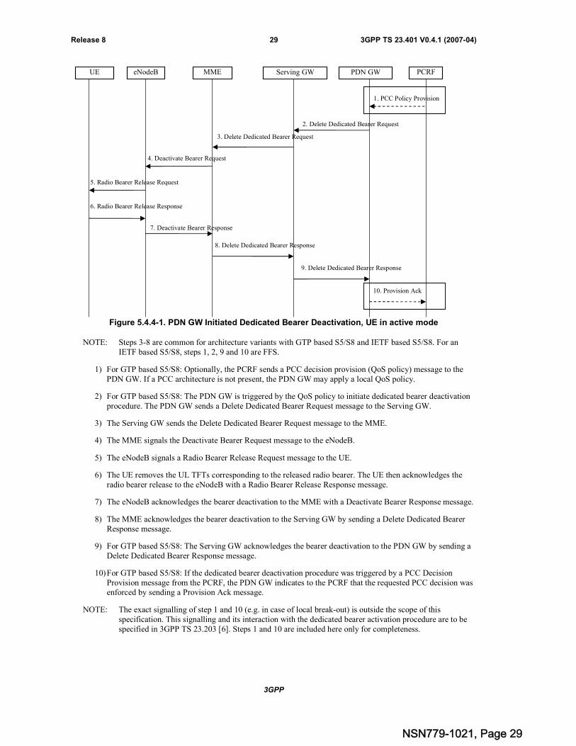
Figure 5.4.4-1. PDN GW Initiated Dedicated Bearer Deactivation, UE in active mode
NOTE: Steps 3-8 are common for architecture variants with GTP based S5/S8 and IETF based S5/S8. For anIETF based S5/S8, steps 1, 2, 9 and 10 are FFS.
1) For GTP based S5/S8: Optionally, the PCRF sends a PCC decision provision (QoS policy) message to thePDN GW. If a PCC architecture is not present, the PDN GW may apply a local QoS policy.
2) For GTP based S5/S8: The PDN GW is triggered by the QoS policy to initiate dedicated bearer deactivationprocedure. The PDN GW sends a Delete Dedicated Bearer Request message to the Serving GW.
3) The Serving GW sends the Delete Dedicated Bearer Request message to the MME.
4) The MME signals the Deactivate Bearer Request message to the eNodeB.
5) The eNodeB signals a Radio Bearer Release Request message to the UE.
6) The UE removes the UL TFTs corresponding to the released radio bearer. The UE then acknowledges theradio bearer release to the eNodeB with a Radio Bearer Release Response message.
7) The eNodeB acknowledges the bearer deactivation to the MME with a Deactivate Bearer Response message.
8) The MME acknowledges the bearer deactivation to the Serving GW by sending a Delete Dedicated BearerResponse message.
9) For GTP based S5/S8: The Serving GW acknowledges the bearer deactivation to the PDN GW by sending aDelete Dedicated Bearer Response message.
10)For GTP based S5/S8: If the dedicated bearer deactivation procedure was triggered by a PCC DecisionProvision message from the PCRF, the PDN GW indicates to the PCRF that the requested PCC decision wasenforced by sending a Provision Ack message.
NOTE: The exact signalling of step 1 and 10 (e.g. in case of local break-out) is outside the scope of thisspecification. This signalling and its interaction with the dedicated bearer activation procedure are to bespecified in 3GPP TS 23.203 [6]. Steps 1 and 10 are included here only for completeness.
1. PCC Policy Provision
3. Delete Dedicated Bearer Request
MME Serving GW PDN GW PCRF
4. Deactivate Bearer Request
5. Radio Bearer Release Request
2. Delete Dedicated Bearer Request
6. Radio Bearer Release Response
7. Deactivate Bearer Response
8. Delete Dedicated Bearer Response
9. Delete Dedicated Bearer Response
10. Provision Ack
eNodeBUE
NSN779-1021, Page 29
3GPP
3GPP TS 23.401 V0.4.1 (2007-04)30Release 8
5.5 Handover
<This section describes the functionality and signalling flows for intra and inter-RAT handover etc. Handovers betweenIPv4 and IPv6 can be documented here. For intra-EUTRAN handover it is FFS how this section relates to the RAN 3TS. >
5.5.1 Inter eNodeB handover with CN node relocation
This procedure shall be used for inter eNodeB handover in the following cases:
There is no X2 connectivity between source eNodeB and target eNodeB (or it is not desired to be utilized) or There is no S1-MME connectivity between target eNodeB and source MME (or it is not desired to be utilized)
or There is no S1-U connectivity between target eNodeB and source Serving GW (or it is not desired to be
utilized)To cover all the above scenarios and their combination this Inter eNodeB handover with CN node relocation proceduredoes not rely on:
- signalling on X2 between source eNodeB and target eNodeB,
- signalling on S1-MME between target eNodeB and source MME, nor
- signalling on S1-U between target eNodeB and source Serving GW, nor
- signalling on S1-MME between source eNodeB and target MME, nor
- signalling on S1-U between source eNodeB and target Serving GW
NOTE: Whether X2 is used to find out the non existence of S1-MME or S1-U connectivity is out of scope of thisprocedure.
This inter eNodeB handover with CN node relocation procedure can be used to relocate MME, Serving GW or both. Itis FFS what triggers the procedure, i.e. if we have separate triggers for MME and Serving GW relocation and/or onlyone trigger for MME relocation and/or only Serving GW relocation.
Forwarding of packets may be used from the source eNodeB to the target eNodeB. Packet forwarding can take placeeither directly from the source eNodeB to the target eNodeB, or indirectly from the source eNodeB to the targeteNodeB via one or more intermediate node in the core network.
Editor's Note: Other ways of sending packets, e.g. without sending to the source eNodeB, are FFS.
The MMEs (source and target) use configuration to determine whether indirect forwarding is to be performed. It is FFShow the MMEs decide about the indirect forwarding.
5.5.2 Inter RAT handover
5.5.2.1 E-UTRAN to UMTS/GPRS Inter RAT handover
Editor's note: It is an open issue whether the final flow will be split into separate preparation phase and executionphase or combined into single comprehensive flow.
Editor's note: The case when the target Gb based system does not support PS handovers is FFS.
NSN779-1021, Page 30
3GPP
3GPP TS 23.401 V0.4.1 (2007-04)31Release 8
5.5.2.1.1 Preparation phase
Figure 5.5.2-1: E-UTRAN to UMTS/GPRS Inter RAT HO, preparation phase
1) The source eNodeB decides to initiate a PS handover to the target access network within UMTS/GPRS. At thispoint both uplink and downlink user data is transmitted via the following: Bearer(s) between UE and sourceeNodeB, GTP tunnel(s) between source eNodeB, Serving GW and PDN GW.
2) The source eNodeB sends a Relocation Required message to the source MME to request the CN to establishresources in the target access network, target SGSN and the Serving GW.
3) The source MME will forward the request to the target SGSN using the message Forward Relocation Request.This message includes all (Release 8) PDP contexts corresponding to the bearers established in the sourcesystem and the uplink Tunnel endpoint parameters of the Serving GW.
Editor's Note: The actual tunnel endpoint parameters need to be defined.
4) The target SGSN will request the target access network to establish the necessary resources.
The target access network allocates the resources and returns the applicable parameters to the target SGSN. Thedetails of this source access network specific signalling are described in 3GPP TS 23.060 [7] for Iu mode and in3GPP TS 43.129 [8] for Gb mode.
Editor's note: The case when the Serving GW is changed is FFS.
Editor's note: It's currently an open issue if the source MME or the target SGSN updates the Serving GW about themapping between bearers and PDP contexts.
5) The target SGSN completes the preparation phase by sending the message Forward Relocation Response to thesource MME.
UESource
eNodeBTarget
Access NW Source MME Target SGSN Serving GW HSS
1. Handover Initiation
2. Relocation Required3. Forward Relocation Request
5. Forward Relocation Response
PDN GW
Uplink and Downlink Payload PDUs
4. Target SGSN prepares the TargetAccess NW for the Inter RAT HO
NSN779-1021, Page 31
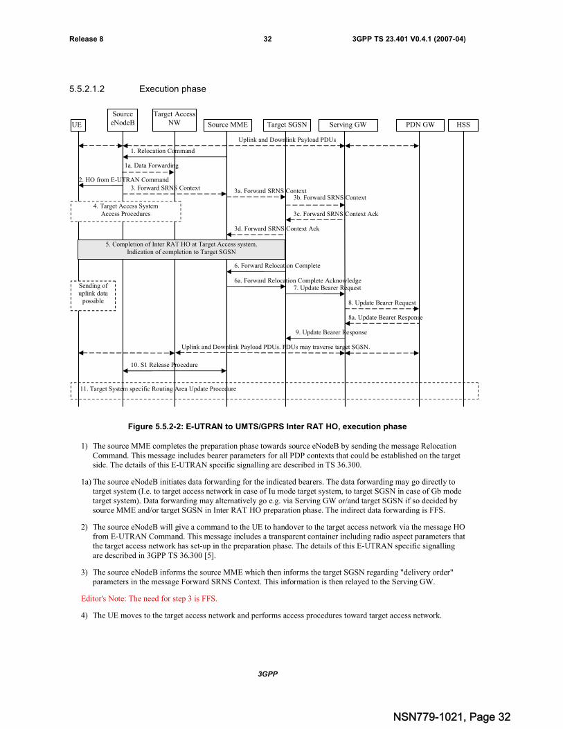
3GPP
3GPP TS 23.401 V0.4.1 (2007-04)32Release 8
5.5.2.1.2 Execution phase
Figure 5.5.2-2: E-UTRAN to UMTS/GPRS Inter RAT HO, execution phase
1) The source MME completes the preparation phase towards source eNodeB by sending the message RelocationCommand. This message includes bearer parameters for all PDP contexts that could be established on the targetside. The details of this E-UTRAN specific signalling are described in TS 36.300.
1a) The source eNodeB initiates data forwarding for the indicated bearers. The data forwarding may go directly totarget system (I.e. to target access network in case of Iu mode target system, to target SGSN in case of Gb modetarget system). Data forwarding may alternatively go e.g. via Serving GW or/and target SGSN if so decided bysource MME and/or target SGSN in Inter RAT HO preparation phase. The indirect data forwarding is FFS.
2) The source eNodeB will give a command to the UE to handover to the target access network via the message HOfrom E-UTRAN Command. This message includes a transparent container including radio aspect parameters thatthe target access network has set-up in the preparation phase. The details of this E-UTRAN specific signallingare described in 3GPP TS 36.300 [5].
3) The source eNodeB informs the source MME which then informs the target SGSN regarding "delivery order"parameters in the message Forward SRNS Context. This information is then relayed to the Serving GW.
Editor's Note: The need for step 3 is FFS.
4) The UE moves to the target access network and performs access procedures toward target access network.
UE
SourceeNodeB
Target AccessNW Source MME Target SGSN Serving GW HSSPDN GW
Uplink and Downlink Payload PDUs
1. Relocation Command
2. HO from E-UTRAN Command
Sending ofuplink data
possible
4. Target Access SystemAccess Procedures
3a. Forward SRNS Context3b. Forward SRNS Context
3c. Forward SRNS Context Ack
3d. Forward SRNS Context Ack
6. Forward Relocation Complete
6a. Forward Relocation Complete Acknowledge
10. S1 Release Procedure
7. Update Bearer Request
8. Update Bearer Request
8a. Update Bearer Response
9. Update Bearer Response
Uplink and Downlink Payload PDUs. PDUs may traverse target SGSN.
3. Forward SRNS Context
11. Target System specific Routing Area Update Procedure
5. Completion of Inter RAT HO at Target Access system.Indication of completion to Target SGSN
1a. Data Forwarding
NSN779-1021, Page 32
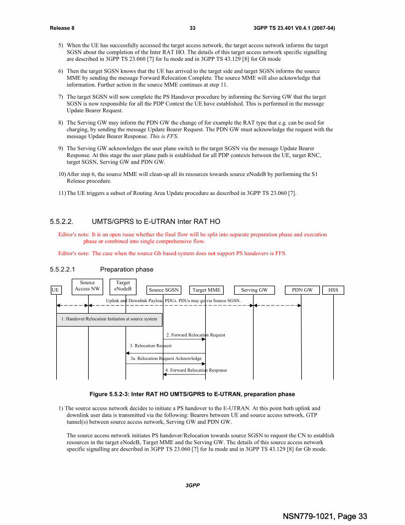
3GPP
3GPP TS 23.401 V0.4.1 (2007-04)33Release 8
5) When the UE has successfully accessed the target access network, the target access network informs the targetSGSN about the completion of the Inter RAT HO. The details of this target access network specific signallingare described in 3GPP TS 23.060 [7] for Iu mode and in 3GPP TS 43.129 [8] for Gb mode
6) Then the target SGSN knows that the UE has arrived to the target side and target SGSN informs the sourceMME by sending the message Forward Relocation Complete. The source MME will also acknowledge thatinformation. Further action in the source MME continues at step 11.
7) The target SGSN will now complete the PS Handover procedure by informing the Serving GW that the targetSGSN is now responsible for all the PDP Context the UE have established. This is performed in the messageUpdate Bearer Request.
8) The Serving GW may inform the PDN GW the change of for example the RAT type that e.g. can be used forcharging, by sending the message Update Bearer Request. The PDN GW must acknowledge the request with themessage Update Bearer Response. This is FFS.
9) The Serving GW acknowledges the user plane switch to the target SGSN via the message Update BearerResponse. At this stage the user plane path is established for all PDP contexts between the UE, target RNC,target SGSN, Serving GW and PDN GW.
10)After step 6, the source MME will clean-up all its resources towards source eNodeB by performing the S1Release procedure.
11)The UE triggers a subset of Routing Area Update procedure as described in 3GPP TS 23.060 [7].
5.5.2.2. UMTS/GPRS to E-UTRAN Inter RAT HO
Editor's note: It is an open issue whether the final flow will be split into separate preparation phase and executionphase or combined into single comprehensive flow.
Editor's note: The case when the source Gb based system does not support PS handovers is FFS.
5.5.2.2.1 Preparation phase
Figure 5.5.2-3: Inter RAT HO UMTS/GPRS to E-UTRAN, preparation phase
1) The source access network decides to initiate a PS handover to the E-UTRAN. At this point both uplink anddownlink user data is transmitted via the following: Bearers between UE and source access network, GTPtunnel(s) between source access network, Serving GW and PDN GW.
The source access network initiates PS handover/Relocation towards source SGSN to request the CN to establishresources in the target eNodeB, Target MME and the Serving GW. The details of this source access networkspecific signalling are described in 3GPP TS 23.060 [7] for Iu mode and in 3GPP TS 43.129 [8] for Gb mode.
UE
SourceAccess NW
TargeteNodeB Source SGSN Target MME Serving GW HSS
2. Forward Relocation Request
3. Relocation Request
3a. Relocation Request Acknowledge
4. Forward Relocation Response
PDN GW
Uplink and Downlink Payload PDUs. PDUs may go via Source SGSN.
1. Handover/Relocation Initiation at source system
NSN779-1021, Page 33

3GPP
3GPP TS 23.401 V0.4.1 (2007-04)34Release 8
2) The source SGSN will forward the request to the target MME using the message Forward Relocation Request.This message includes all (Rel-8) PDP contexts that are established in the source UMTS/GPRS system and theuplink Tunnel endpoint parameters of the Serving GW.
Editor's Note: The actual tunnel endpoint parameters need to be defined
3) The target MME will request the target eNodeB to establish the bearer(s) by sending the message RelocationRequest. This request includes the uplink Tunnel endpoint parameters received in the previous step.
3a) The target eNodeB allocates the request resources and returns the applicable parameters to the target MME inthe message Relocation Request Acknowledge.
Editor's Note: The case when the Serving GW is changed is FFS.
4) The target MME completes the preparation phase by sending the message Forward Relocation Response to thesource SGSN.
5.5.2.2.2 Execution phase
Figure 5.5.2-4: Inter RAT HO UMTS/GPRS to E-UTRAN, execution phase
1) The source SGSN completes the preparation phase towards source access network. The procedures for this aredescribed in detail in 3GPP TS 23.060 [7] for Iu mode and in 3GPP TS 43.129 [8] for Gb mode.
The source access network will command to the UE to handover to the target eNodeB. The access networkspecific message to UE includes a transparent container including radio aspect parameters that the target eNodeB
UE
SourceAccess NW
eNodeB
Source SGSN Target MME Serving GW HSSPDN GW
Uplink and Downlink Payload PDUs. PDUs may traverse source SGSN
Sending ofuplink data
possible
4. LTE Access Procedures
3a. Forward SRNS Context
3b. Forward SRNS Context
3c. Forward SRNS Context Ack
3d. Forward SRNS Context Ack5. HO to LTE Complete
6. Relocation Complete
7. Forward Relocation Complete
7a. Forward Relocation Complete Acknowledge
8. Update Bearer Request
9a. Update Bearer Response
10. Update Bearer Response
Uplink and Downlink Payload PDUs
12. TAU Procedure
1. UE is commanded to make HO as specified forthe source access system
2. Access Context forwarding to source SGSN forthe source access system
11. Source Access system resourcerelease
1a. Data Forwarding
9. Update Bearer Request
NSN779-1021, Page 34
3GPP
3GPP TS 23.401 V0.4.1 (2007-04)35Release 8
has set-up in the preparation phase. The procedures for this are described in detail in 3GPP TS 23.060 [7] for Iumode access networks and in 3GPP TS 43.129 [8] for Gb mode access networks.
1a) The source network (I.e. source access network in case of Iu mode source system or source SGSN in case of Gbmode source system) initiates data forwarding for the indicated RABs/PDP contexts. The data forwarding maygo directly to target eNodeB. Data forwarding may alternatively go e.g. via source SGSN or/and Serving GW ifso decided by source SGSN and/or target MME in Inter RAT HO preparation phase. The indirect dataforwarding is FFS.
2) Depending on the source access network type, the Source access network may deliver source access networkcontexts to the source SGSN.
3) The source SGSN informs the target MME regarding source access network contexts in the message ForwardSRNS Context. This information is then relayed to the Serving GW.
The need for the steps 2 & 3 are FFS.
4) The UE moves to the E-UTRAN and performs access procedures toward target eNodeB.
5) When the UE has got access to target eNodeB it sends the message HO to E-UTRAN Complete.
6) When the UE has successfully accessed the target eNodeB, the target eNodeB informs the target MME bysending the message Relocation Complete.
7) Then the target MME knows that the UE has arrived to the target side and target MME informs the source SGSNby sending the message Forward Relocation Complete. The source SGSN will also acknowledge thatinformation. Further action in the source SGSN continues at step 11.
8) The target MME will now complete the PS Handover procedure by informing the Serving GW that the targetMME is now responsible for all the bearers the UE have established. This is performed in the message UpdateBearer Request.
9) The Serving GW may inform the PDN GW the change of for example the RAT type that e.g. can be used forcharging, by sending the message Update Bearer Request. The PDN GW must acknowledge the request with themessage Update Bearer Response. This is FFS.
10)The Serving GW acknowledges the user plane switch to the target MME via the message Update BearerResponse. At this stage the user plane path is established for all bearers between the UE, target eNodeB, ServingGW and PDN GW.
11)After step 7 the source SGSN will clean-up all its resources towards source access network by performing thenecessary procedures. The procedures for this are described in detail in 3GPP TS 23.060 [7] for Iu mode accessnetworks and in 3GPP TS 43.129 [8] for Gb mode access networks.
12)The UE triggers a subset of Tracking Area Update procedure (see clause 5.3.2)
5.6 Information Storage
<This section describes the context information that is stored in the different nodes, eg in HSS, PDN GW, Serving GW,MME, eNodeB, UE, etc.
It also gives a high level overview of recovery and restoration procedures>
5.7 Charging
< This section gives a high level overview of the charging capabilities in EPC/E-UTRAN.>
5.8 Interactions with Other Services
< This section describes the interactions with other services/features, eg MBMS, location services, emergency/priorityaccess, possibly terminal configuration, etc.>
NSN779-1021, Page 35

3GPP
3GPP TS 23.401 V0.4.1 (2007-04)36Release 8
Annex A (Normative):Agreed requirements, principles and content that should bemoved to other TSs< This section describes issues and agreements that, prior to approval of this Technical Specification, should be movedto other normative specifications, etc.>
A.1 Requirements derived from technical analysisThe EPS shall support
- IPv4 only terminals,
- IPv6 only terminals, and
- dual stack terminals.
The HPLMN operator shall be able to control whether or not an IPv4 only or an IPv6 only terminal is allowed access tothe network.
NSN779-1021, Page 36
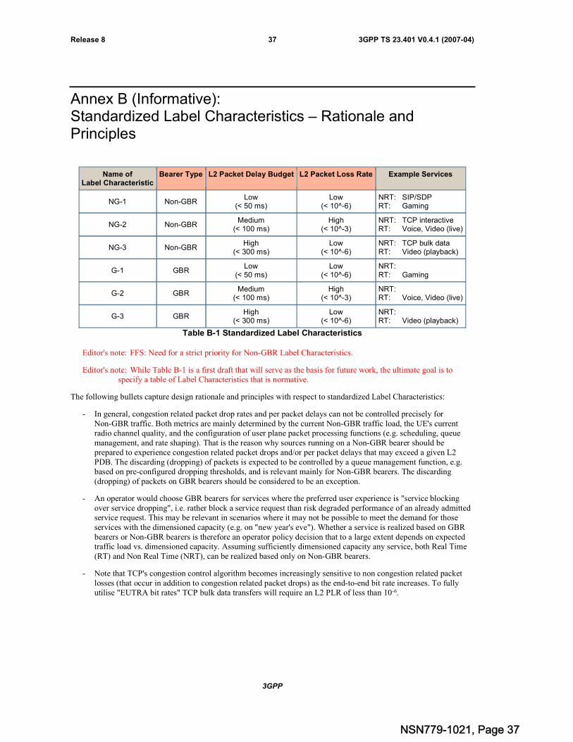
3GPP
3GPP TS 23.401 V0.4.1 (2007-04)37Release 8
Annex B (Informative):Standardized Label Characteristics – Rationale andPrinciples
Name ofLabel Characteristic
Bearer Type L2 Packet Delay Budget L2 Packet Loss Rate Example Services
NG-1 Non-GBRLow
(< 50 ms)Low
(< 10^-6)NRT: SIP/SDPRT: Gaming
NG-2 Non-GBRMedium
(< 100 ms)High
(< 10^-3)NRT: TCP interactiveRT: Voice, Video (live)
NG-3 Non-GBRHigh
(< 300 ms)Low
(< 10^-6)NRT: TCP bulk dataRT: Video (playback)
G-1 GBRLow
(< 50 ms)Low
(< 10^-6)NRT:RT: Gaming
G-2 GBRMedium
(< 100 ms)High
(< 10^-3)NRT:RT: Voice, Video (live)
G-3 GBRHigh
(< 300 ms)Low
(< 10^-6)NRT:RT: Video (playback)
Table B-1 Standardized Label Characteristics
Editor's note: FFS: Need for a strict priority for Non-GBR Label Characteristics.
Editor's note: While Table B-1 is a first draft that will serve as the basis for future work, the ultimate goal is tospecify a table of Label Characteristics that is normative.
The following bullets capture design rationale and principles with respect to standardized Label Characteristics:
- In general, congestion related packet drop rates and per packet delays can not be controlled precisely forNon-GBR traffic. Both metrics are mainly determined by the current Non-GBR traffic load, the UE's currentradio channel quality, and the configuration of user plane packet processing functions (e.g. scheduling, queuemanagement, and rate shaping). That is the reason why sources running on a Non-GBR bearer should beprepared to experience congestion related packet drops and/or per packet delays that may exceed a given L2PDB. The discarding (dropping) of packets is expected to be controlled by a queue management function, e.g.based on pre-configured dropping thresholds, and is relevant mainly for Non-GBR bearers. The discarding(dropping) of packets on GBR bearers should be considered to be an exception.
- An operator would choose GBR bearers for services where the preferred user experience is "service blockingover service dropping", i.e. rather block a service request than risk degraded performance of an already admittedservice request. This may be relevant in scenarios where it may not be possible to meet the demand for thoseservices with the dimensioned capacity (e.g. on "new year's eve"). Whether a service is realized based on GBRbearers or Non-GBR bearers is therefore an operator policy decision that to a large extent depends on expectedtraffic load vs. dimensioned capacity. Assuming sufficiently dimensioned capacity any service, both Real Time(RT) and Non Real Time (NRT), can be realized based only on Non-GBR bearers.
- Note that TCP's congestion control algorithm becomes increasingly sensitive to non congestion related packetlosses (that occur in addition to congestion related packet drops) as the end-to-end bit rate increases. To fullyutilise "EUTRA bit rates" TCP bulk data transfers will require an L2 PLR of less than 10-6.
NSN779-1021, Page 37
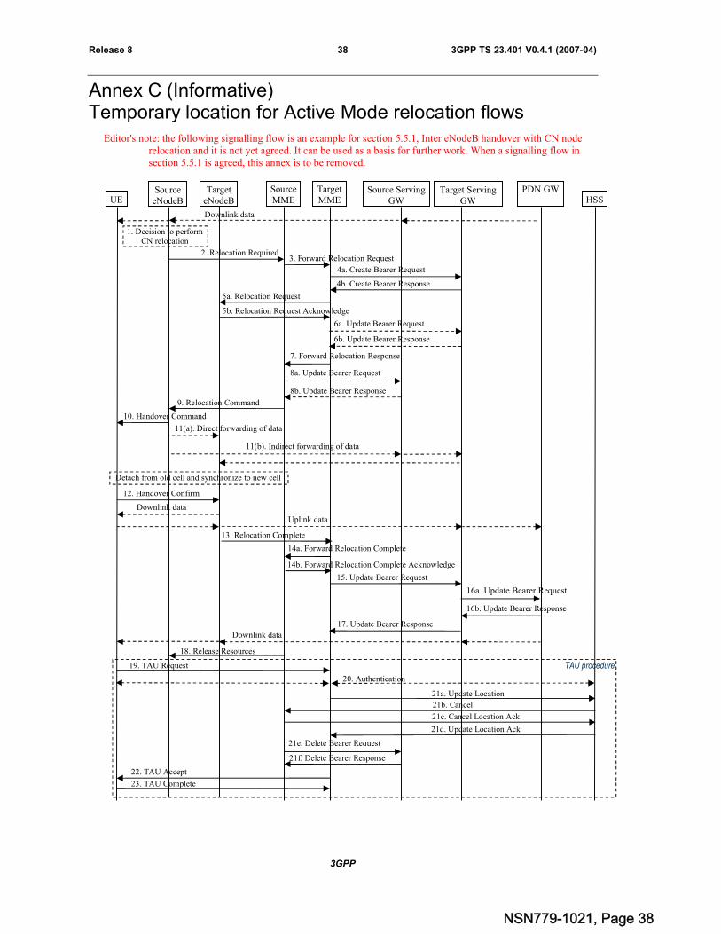
3GPP
3GPP TS 23.401 V0.4.1 (2007-04)38Release 8
Annex C (Informative)Temporary location for Active Mode relocation flows
Editor's note: the following signalling flow is an example for section 5.5.1, Inter eNodeB handover with CN noderelocation and it is not yet agreed. It can be used as a basis for further work. When a signalling flow insection 5.5.1 is agreed, this annex is to be removed.
UESource
eNodeBSourceMME
Source ServingGW
PDN GWTargetMME
Target ServingGW
TargeteNodeB
Detach from old cell and synchronize to new cell
TAU procedure
HSS
16a. Update Bearer Request
17. Update Bearer Response
15. Update Bearer Request
Downlink data
2. Relocation Required
Downlink data
1. Decision to performCN relocation
3. Forward Relocation Request
4a. Create Bearer Request
4b. Create Bearer Response
5a. Relocation Request
5b. Relocation Request Acknowledge
6a. Update Bearer Request
6b. Update Bearer Response
7. Forward Relocation Response
8a. Update Bearer Request
8b. Update Bearer Response
9. Relocation Command
10. Handover Command
11(a). Direct forwarding of data
11(b). Indirect forwarding of data
12. Handover Confirm
Downlink data
Uplink data
13. Relocation Complete
14a. Forward Relocation Complete
14b. Forward Relocation Complete Acknowledge
18. Release Resources
19. TAU Request
20. Authentication
21a. Update Location
21b. CancelLocation21c. Cancel Location Ack
21d. Update Location Ack
21e. Delete Bearer Request
21f. Delete Bearer Response
23. TAU Complete
22. TAU Accept
16b. Update Bearer Response
NSN779-1021, Page 38

3GPP
3GPP TS 23.401 V0.4.1 (2007-04)39Release 8
1) The source eNodeB decides to perform a handover to the target eNodeB. This can be triggered e.g. by no X2connectivity to the target eNodeB, or by configuration in the source eNodeB showing that the target eNodeBdoes not have S1_MME connectivity to the source MME, or by an error indication from the target eNodeB afteran unsuccessful X2-based handover.
2) The source eNodeB sends Relocation Required to the source MME.
3) The source MME selects the target MME and sends a Forward Relocation Request message to it, which includesthe UE context in the source MME.
4) The target MME decides whether to change the Serving GW and selects a target Serving GW. The target MMEsends a Create Bearer Request message to the target Serving GW, including information about the establishedbearers of the UE and identity of the PDN GW and its TEIDs. The target Serving GW allocates TEIDs for theuplink traffic on S1_U reference point (one TEID per bearer). The target Serving GW sends anacknowledgement message back to the target MME, which include these newly allocated TEIDs.
5) The target MME sends Relocation Request message to the target eNodeB. This message creates the UE contextin the target eNodeB, including information about the bearers, and the security context. The target eNodeB sendsa Relocation Request Acknowledge message to the MME. This includes the TEIDs allocated at the targeteNodeB for downlink traffic on S1_U reference point (one TEID per bearer).
6) If indirect forwarding is used, the target MME sets up forwarding parameters in the target Serving GW.
7) The target MME sends a Forward Relocation Response message to the source MME.
8) If indirect forwarding is used, the source MME updates the source Serving GW about the tunnels used to thetarget Serving GW.
9) The source MME sends a Relocation Command message to the source eNodeB.
10)The Handover Command is sent to the UE. The UE must be made aware that a CN relocation is beingperformed, since it will have to perform a Tracking Area Update (see below). The UE detaches from the old celland synchronizes to the new cell.
11)The source eNodeB may start forwarding of downlink data from the source eNodeB to the target eNodeB. Thismay be either direct or indirect forwarding.
12)After the UE has successfully synchronized to the target cell, it sends a Handover Confirm message to the targeteNodeB. Downlink packets forwarded from the source eNodeB can be sent to the UE. Also, uplink packets canbe sent from the UE, which are forwarded to the target Serving GW and the PDN GW.
13)The target eNodeB sends a Relocation Complete message to the target MME.
14)The target MME sends a Forward Relocation Complete to the source MME. The source MME in response sendsa Forward Relocation Complete Acknowledge to the target MME.
15)The target MME sends an Update Bearer Request to the target Serving GW. This includes the TEIDs allocated atthe target eNodeB for downlink traffic.
16)The target Serving GW assigns TEIDs (one per bearer) for downlink traffic from the PDN GW. It sends anUpdate Bearer Request to the PDN GW, including the assigned TEIDs. The PDN GW starts sending downlinkpackets to the target Serving GW using the newly received TEIDs. These downlink packets will use the newdownlink path via the target Serving GW and target eNodeB. An Update Bearer Response is sent back to thetarget Serving GW.
17)The target Serving GW sends an Update Bearer Response to the target MME.
18)After the source MME has received the Forward Relocation Complete message, it sends a Release Resourcesmessage to the source eNodeB. The source eNodeB can the release resources in the source eNodeB. The timingof this message and the timing of releasing the resources are FFS.
19)As soon as the handover to the target eNodeB is completed, the UE sends a Tracking Area Update Requestmessage, which arrives to the target MME.
20)The target MME may optionally authenticate the UE
NSN779-1021, Page 39

3GPP
3GPP TS 23.401 V0.4.1 (2007-04)40Release 8
21)
a) The target MME updates the HSS by sending an Update Location message
b) The HSS sends a Cancel Location message to the source MME.
c) The source MME sends a Cancel Location Ack message to the HSS.
d) After the HSS has received the Cancel Location Ack message, it sends an Update Location Ack to the targetMME.
e) The source MME releases the bearer in the source Serving GW by sending a Delete Bearer Request message.
f) The source Serving GW sends a Delete Bearer Response to the source MME.
22)The target MME sends a Tracking Area Update Accept to the UE, which include a new S-TMSI allocated by thetarget MME.
23)The UE acknowledges the new S-TMSI by sending a Tracking Area Update Complete message.
NSN779-1021, Page 40

3GPP
3GPP TS 23.401 V0.4.1 (2007-04)41Release 8
Annex D:Change history
Change historyDate TSG # TSG Doc. CR Rev Subject/Comment Old New
2006-12 Initial version in S2-070327 - 0.0.0
2007-01 SA2 #56 First update of TS skeleton in S2-070544. 0.0.0 0.0.1
2007-01 SA2 #56 Second update of TS skeleton in S2-070545. 0.0.1 0.0.2
2007-01 SA2 #56 Third update of TS skeleton in S2-070549. 0.0.2 0.0.3
2007-01 SA2 #56 Inclusion of documents agreed at SA2 #56. S2-070564, S2-070329, S2-070591 and, S2-070572.
0.0.3 0.1.0
2007-02 SA2#56bAdhoc
Inclusion of documents agreed at SA2 #56b Adhoc: S2-071047, S2-071050, S2-071051, S2-071053, S2-071056
0.1.0 0.2.0
2007-02 EmailReview
Correction of implementation of S2-071051, S2-071050 0.2.0 0.2.1
2007-03 SA2#56cAdhoc
Inclusion of documents agreed at Sa2 #56c Adhoc: S2-071500, S2-071512, S2-071590, S2-071593, S2-071604,S2-071609, S2-071610, S2-071611, S2-071612, S2-071613, S2-071614, S2-071615, S2-071616
0.2.1 0.3.0
2007-04 Terminologyupdate
Update the terminology used within specification 0.3.0 0.4.0
2007-04 Editorial Editorial tidy up 0.4.0 0.4.1
NSN779-1021, Page 41