3ddes
DESCRIPTION
3ddesTRANSCRIPT

CADPIPE 3D DESIGN®

CADPIPE 3D DESIGN
©2006 Orange TechnologiesAll Rights Reserved
This publication, or parts thereof, may not be reproduced in any form, by anymethod, for any purpose.
Orange Technologies makes no warranty, either expressed or implied, includ-ing but not limited to any implied warranties of merchantability or fitness for aparticular purpose, regarding these materials and makes such materials avail-able solely on an “as-is” basis.
In no event shall Orange Technologies be liable to anyone for special, collat-eral, incidental, or consequential damages in connection with or arising out ofpurchase or use of these materials. The sole and exclusive liability to OrangeSystems, regardless of the form of action, shall not exceed the purchase priceof the materials described herein.
Orange Technologies reserves the right to revise and improve its products asit sees fit. This publication describes the state of this product at the time of itspublication, and may not reflect the product at all times in the future.
CADPIPE uses AutoCAD ® as the graphics driver.
CADPIPE is a registered trademark of International Software Systems Inc., a wholly-owned subsidiary of Orange SystemsAutoCAD and AutoLISP ® are registered in the U.S. Patent and Trademark Office by Autodesk, Inc.
IBM and PC-DOS are registered trademarks of International Business Machines Corporation.Windows is a trademark of Microsoft Corporation

ContentsINTRODUCTION TO 3D DESIGN.........................................8Menus and Toggles ...................................................................................... 8
Toggles .......................................................................................................................... 9Toolbars ......................................................................................................................... 9
CADPIPE Specifications .............................................................................10Starting to Draw ...........................................................................................10
SPECIFICATION OPTIONS................................................ 11Specification Options ................................................................................. 11
Line Number ................................................................................................................ 12Material Spec ............................................................................................................... 12Process ........................................................................................................................ 12Database ...................................................................................................................... 12Spec Check/Spec Override ........................................................................................ 12Spec Alternates ........................................................................................................... 13Extended Ends............................................................................................................ 13Pipe/Fitting Specifications ......................................................................................... 13End types..................................................................................................................... 14Pipe Size Text .............................................................................................................. 14Gaskets/Lining/Bolts .................................................................................................. 15Flange Specifications ................................................................................................. 15Valve Specifications.................................................................................................... 15Clamp Specifications .................................................................................................. 15
Customizing the Specifications ................................................................15Customizing the Database .........................................................................15
PIPE, FITTINGS, AND EQUIPMENT .................................16Starting to Draw ...........................................................................................16
Start a Run ................................................................................................................... 16Join To ......................................................................................................................... 17
Options .........................................................................................................18Options - Current Run ................................................................................................ 18Options - Settings ....................................................................................................... 23Options - Fitting Placement ........................................................................................ 24Options - Shop/Field/Layer ......................................................................................... 26Options - Tooltip Query ............................................................................................... 27
Valves............................................................................................................29Placing Valves ............................................................................................................. 29Valve Stem and Handwheel ....................................................................................... 29
Equipment ....................................................................................................30

Pumps .......................................................................................................................... 30Vessels ......................................................................................................................... 33Exchangers ................................................................................................................. 38
Routing Line ......................................................................42A Typical Command Sequence .................................................................................. 42The Pedit Option ......................................................................................................... 44Offset-45....................................................................................................................... 48The Reference Option ................................................................................................. 49The Join Option ........................................................................................................... 50The Designation Option.............................................................................................. 50Multiple Routing Lines and Fittings ........................................................................... 51Sloped Lines ............................................................................................................... 51
Auto-Elbow ...................................................................................................52Insertion Point ............................................................................................................. 52Typical Command Sequence ..................................................................................... 53Error Messages ........................................................................................................... 53Warning Messages...................................................................................................... 54Comments ................................................................................................................... 54
Auto-Pipe ......................................................................................................55Typical Command Sequence ..................................................................................... 55
AUTO-ROUTE.....................................................................56Horizontal Auto-Route .................................................................................56Vertical Auto-Route .....................................................................................57
Horizontal to vertical run ............................................................................................ 57Vertical run................................................................................................................... 58Vertical to horizontal run ............................................................................................ 59
Join................................................................................................................60Snap ..............................................................................................................61Close .............................................................................................................63Multiple Auto-Route Pipe Run....................................................................63
COLLISION CHECKING.....................................................64Interactive Collision Checking ..................................................................64
View Collision .............................................................................................................. 65Query Pipe ................................................................................................................... 65
Batch Collision Checking ..........................................................................67Color ............................................................................................................................ 67Check ........................................................................................................................... 68View.............................................................................................................................. 68Recolor ........................................................................................................................ 69

EDIT TOOLS.......................................................................703D DESIGN Move.........................................................................................703D DESIGN Copy .........................................................................................713D DESIGN Erase ........................................................................................713D Design Mirror .........................................................................................723D Design Rotate .........................................................................................733D Design Rotate 3D ...................................................................................74Move Last Fitting.........................................................................................753D DESIGN Query........................................................................................75
Place Size .................................................................................................................... 76Place Length ............................................................................................................... 76Place Slope .................................................................................................................. 76Place Line Designation............................................................................................... 77Place Description ........................................................................................................ 77Place Elevation............................................................................................................ 77
Insert Fittings and Valves ..........................................................................78Inserting a Valve .......................................................................................................... 80
Fitting Conversion ......................................................................................81Stretch Pipe..................................................................................................81
Typical Command Sequence ..................................................................................... 81ISOLATE .......................................................................................................84
Dgitize Run .................................................................................................................. 84Select Objects ............................................................................................................. 85Ignore Annotation ....................................................................................................... 85
User Notes ....................................................................................................85Digitize Run ................................................................................................................. 86Select Objects ............................................................................................................. 87
BOM Tag.......................................................................................................88
ISO DRAWINGS .................................................................90Iso Pipe .........................................................................................................90
Projection .................................................................................................................... 90Scale ............................................................................................................................ 91Spool Sheet Number .................................................................................................. 91ISO Checkmarks ......................................................................................................... 92
Label Function .............................................................................................92Placing Labels ............................................................................................................. 92Auto Labeling .............................................................................................................. 94Move/Erase/Print Label ............................................................................................... 94Label Options .............................................................................................................. 94New Session ............................................................................................................... 95Open Session .............................................................................................................. 95Save Session............................................................................................................... 96

Report .......................................................................................................................... 96Place report on drawing ............................................................................................. 97Exit ............................................................................................................................... 97
CADPIPE AUTO-ISO Program....................................................................98Creating the Universal Data Exchange (UDE) file .................................................... 98
REPORTS ...........................................................................99Pipe and Fittings Reports...........................................................................99
Pipe Reports ................................................................................................................ 99Pipe Report ................................................................................................................ 100Fitting Report............................................................................................................. 100Valve Report .............................................................................................................. 101Place report on drawing ........................................................................................... 102
Section Views/Spooling .................................................103Sheet Layout ..............................................................................................103
New Layout ............................................................................................................... 103New Layout with Wizard........................................................................................... 103Manual Setup............................................................................................................. 104
Section/Floor Plan Views. . . ....................................................................104Setup/Generate ......................................................................................................... 105Section ....................................................................................................................... 105Floor Plan .................................................................................................................. 107Generate .................................................................................................................... 108
Clear Clipping Planes ...............................................................................109Spools .........................................................................................................109
Setup .......................................................................................................................... 109Generate ..................................................................................................................... 111
Settings....................................................................................................... 112Dimension Styles ...................................................................................................... 112DIMSCALE ................................................................................................................. 113DIMTXSTY .................................................................................................................. 113DIMASZ ...................................................................................................................... 113DIMTXT ...................................................................................................................... 113
Symbols ...................................................................................................... 114North Arrow ............................................................................................................... 114Revision Cloud.......................................................................................................... 114Pipe End .................................................................................................................... 115Flow Arrow, Small ...................................................................................................... 115Flow Arrow, Large ..................................................................................................... 115Battery Limit .............................................................................................................. 116
Annotation .................................................................................................. 116Valve Dim ................................................................................................................... 116Place Coordinates .................................................................................................... 116W.P. Elevation ............................................................................................................ 117

STRUCTURAL FUNCTIONS ............................................ 118Columns ..................................................................................................... 118
Placing Rectangular Columns ................................................................................. 118Beams as Columns ................................................................................................... 120
Beams .........................................................................................................122Placing Beams .......................................................................................................... 122Beam Size .................................................................................................................. 124
......................................................................................................................................... 125Edit Beam Database ................................................................................................. 127
Joist.............................................................................................................129Placing Joists ............................................................................................................ 129Joist Dimensions ...................................................................................................... 130
Structural Configure .................................................................................131Configure Structural Layers..................................................................................... 131Structural Tooltip Query ........................................................................................... 132

CADPIPE 3D DESIGN
8
INTRODUCTION TO 3D DESIGN
CADPIPE 3D DESIGN is a full three dimensional software program that uses the conventionalAutoCAD environment to allow you to draw piping systems in any direction, without changing usercoordinate systems or projection planes, while automatically checking for interference problems.
The AutoCAD HIDE, SHADE, and RENDER features can be used to create presentation draw-ings of your piping system designs. CADPIPE 3D DESIGN remembers every fitting you draw, andcan generate a bill of materials catalogued according to fitting type. Other 3D DESIGN featuresinclude a Structural function to create your background drawings, an Iso-Pipe function for fabrica-tion drawings, Collision Checking for interference detection, and editing functions to make drawingand editing your pipe design fast and easy.
Menus and Toggles
Built into CADPIPE 3D Design software are pull-down menus and toolbars. These menuscontain all the functions needed to do your piping designs and drawings and automatically load whenyou start a CADPIPE session.
They replace the AutoCAD standard pull-down menus with a combination of AutoCAD andCADPIPE pull-down menus. The CADPIPE pull-down menus available are 3D DESIGN, Place,Tools, Struct, Equip, and Drawing Sheets.
CADPIPE 3D DESIGN

CADPIPE 3D DESIGN
9
Toggles
There are three important toggles on the 3DDESIGN pull-down menu which affect drawing speedand fitting specification.
The Turn Fittings Right toggle sets the CADPIPE 3D turn direction for certain fittings.
The Collision Check toggle tells CADPIPE to check for possible collisions every time youplace a pipe or fitting. You should leave this toggle off unless you are working in an area whereinterference is likely so CADPIPE can place the pipe or fitting without spending time searching forcollisions.
The Auto-Specify toggle controls the specifications for the pipe and fittings you are placing.When the toggle is on, CADPIPE uses the parameters defined in the Specifications Database.
Toolbars
There are three main CADPIPE 3D Design Toolbars: Design, Utilities, and Edit. All othertoolbars can be accessed from the Toolbars sub-menu on the Tools menu. They are: Annota-tions, Pipe_Break, Pipe_Views, Flow_Arrows, PS_Dim_Variables, Sections, Spools, Sym-bols, Label Function, Iso Dimensioning, Struct, and Fittings. The proper Fittings toolbaratuomatically loads depending on your pipe specification. Figure Intro-1 lists the CADPIPE com-mands associated with the main toolbar buttons:
Figure Intro-1
Edit Toolbar
Setup Section View
Pipe Reports
Query
Erase
Copy
Move
Turn Down
Turn Up
Design Toolbar UtilitiesToolbar
Valves
Undo last
Join to
Insert
Cut Pipe
Default Pipe
Auto-Route
Specifications
Start a Run
Options
Collision Check
Iso Pipe
Auto Elbow
Place Routing Line
Auto Pipe
UDE Out
UDE In

CADPIPE 3D DESIGN
10
CADPIPE Specifications
CADPIPE provides a number of pre-defined specifications that determine how your fittings andpipe are drawn. Before you begin to draw, you can include your design information by customizingthe CADPIPE Specifications through the CADPIPE Specification Generator program (see theSpecifications Generator documentation). Once you have set up your design specifications andturned Spec Check on, the pipe and fittings are drawn based on the settings defined in your Speci-fications.
When you select a fitting, CADPIPE 3D DESIGN automatically draws that fitting according to thedesign information defined in the Specification (if Spec Check is on) and the Options menu. Youcan change parameters at any time by selecting Specifications or Options from the 3DDESIGNmenu. CADPIPE 3D DESIGN places the pipe or fitting on the current AutoCAD layer and color.
Starting to Draw
To actually begin drawing pipe, select Start a Run from the 3DDESIGN menu. This tellsCADPIPE 3D DESIGN to begin a new pipe run. The system will prompt you for the line number,elevation, starting point, and direction (the AutoCAD direction angle) of the run.
You can then begin selecting fittings from the menu. CADPIPE 3D DESIGN automatically adds anyfitting selected to the last fitting drawn in a run, unless you select Start a Run again.
If you wish to add to an existing run or return to a previously placed run, use the Join to command.CADPIPE prompts you to select a fitting and any subsequent fittings will be added from this point.
You can use CADPIPE 3D DESIGN’s Auto-Route feature to draw long runs of pipe withoutselecting each and every fitting. Instead of selecting a fitting, choose the Auto-Route option fromone of the menus (see the Auto-Route chapter).
If Spec Check is on (see the Specification Options chapter), the fittings that you draw are con-trolled by the parameters defined in the Options menu, as well as the Specifications menu.

CADPIPE 3D DESIGN
11
SPECIFICATION OPTIONS
CADPIPE 3D DESIGN gives you the ability to define different parameters (rating, schedule, endtype, valve type and flange type) based on the pipe size and specification you are using.
Specification Options
The Specifications menu allows you to change the parameters that define the pipe or fittings youare drawing. When Spec Check is on, CADPIPE uses the settings from the Material Specificationlisted in the CADPIPE 3D Specifications Options dialog box, but when Spec Check is off, youselect the individual pipe and fitting specifications from the dialog box.When you select Specifications from the 3D DESIGN menu, the 3D Design SpecificationOptions dialog box appears (see Figure Spec-1).
Figure Spec-1

CADPIPE 3D DESIGN
12
Line Number
This field sets the line number that will apply to your piping run and fittings. Click this field and typein the line number you want to use for your first run. This information is listed with the pipe or fittingwhen you generate a report.
Material Spec
This field associates a Material Specification with the fitting or pipe you are drawing. The Specifica-tion is listed with the pipe or fitting when you generate a report. It does not appear on the drawingunless you place the line designation text with the Query command.
To enter a spec select a Specification from the list menu. If you have created your own MaterialSpecifications through the CADPIPE Specification Generator program (see the SpecificationGenerator documentation), they are listed in this dialog box. The spec remains until a new Specifi-cation is selected.
Process
This field associates a Process with the fitting or pipe you are drawing. It is listed with the pipe orfitting when you generate a report. The Process does not appear on the drawing unless you placethe line designation text with the Query command.
To enter a process select one from the list menu.
Database
This field allows you to select a fitting database for your drawing session. CADPIPE offers a wideselection of international databases including: ANSI PLUS, DIN, British Standards, AFNOR, JIS,Czecho, Romanian, Russian, Hungarian and Polish. Only those databases that you installed arelisted. You can customize the database through the CADPIPE Database Editor program (see theDatabase Editor documentation).
Spec Check/Spec Override
If you click on Spec Check, Spec Check is activated and the Specification you choose in theMaterial Spec field applies to all settings in the dialog box.
If you change your pipe size, the other fitting and flange specifications are updated according to theMaterial Spec, and if you select a setting that is not allowed for in the Specification, you are given amessage saying that you must turn Spec Check off before you can place the item.
The setting in this dialog box affects the Spec Check toggle in the 3DDESIGN menu.
Click on Spec Override to place an out-of-spec item without turning Spec Check off. Once theout-of-spec item is placed, CADPIPE automatically reactivates Spec Check.

CADPIPE 3D DESIGN
13
Spec Alternates
You can place fittings that are alternates in the spec by activating the Spec Alternate toggle. Thetoggle is on by default. When placing fittings with Spec Check on, any fittings or valves differentfrom the default but contained in your spec are displayed in the Select Alternate Fitting Typedialog box (see Figure Spec-2). Spec alternates are only placed when Spec Check is on.
Refer to the Specification Generator documentation for information on creating spec alternates.
Extended Ends
If the Extended Ends toggle is active, fittings that have extended ends database tables are placedwith extended ends. Extended Ends database tables are not supplied with CADPIPE. However,you can create your own Extended Ends tables. Refer to the Database Editor documentation.
Pipe/Fitting Specifications
This section allows you to change the pipe size, rating, schedule, and end types settings. To select asetting, click on the arrow, scroll through the list of options and select a new setting. If Spec Checkis on, CADPIPE adjusts these parameters automatically according to the Material Spec and pipesize chosen.
Figure Spec-2

CADPIPE 3D DESIGN
14
If you change the pipe size, these parameters change according to the Specification. If Spec Checkis off, you determine the settings for this pipe size. The color and layer are determined by thecurrent AutoCAD LAYER CONTROL SETTINGS.
End types
If you select butt weld or socket weld for your fitting end type, you can set the weld gap. You canset an inlet end type that is different from the outlet end type by toggling off “Same Inlet and Outlet”and picking a different outlet end.
Pipe Size Text
A size tag is included automatically with any default length of pipe you place on your drawing if youclick on “Show Pipe Size.” You select the size and style of text through the “Text Size” and “Style”fields. If you want additional text to appear with the size tag, type the text in the “Identifier” field.You can enter up to nine characters (see Figure Spec-3).
Figure Spec-3
Text is Placed on default length Pipe
Cut To length Pipe has no text

CADPIPE 3D DESIGN
15
Gaskets/Lining/Bolts
Click on these buttons to set your gasket, bolt, and lining thicknesses.
Flange Specifications
In this section you set the parameters for flanges. You can set Flange Type, Face Type, End Typeand Rating. If Spec Check is on these will be set for you.
Valve Specifications
Set your Valve Rating and Valve Ends in this section. If Spec Check is on these will be set for you.
Clamp Specifications
Set your Clamp Type and Manufacturer in this section.
Customizing the Specifications
Customizing the CADPIPE specifications and creating your own specifications is fully explained inthe Specification Generator documentation. All modifications to your Specifications are donethrough the CADPIPE Specification Generator program.
Customizing the Database
Customizing the CADPIPE Database is fully explained in the Database Editor documentation. Allmodifications to the databases are done through the Database Editor program.

CADPIPE 3D DESIGN
16
PIPE, FITTINGS, AND EQUIPMENT
All pipe and fittings drawn with CADPIPE 3D DESIGN get their dimensions either from theMaterial Specifications, into which you enter your design information, or from the settings you enterin the 3D Specifications Options dialog box. Therefore, you have total control over how eachfitting is represented on the drawing.
Starting to Draw
Start a Run
The Start a Run command prompts you to define various settings for a pipe run. Select Start aRun from the 3DDESIGN menu or the Design Toolbar, and you will see the following prompts:
Line Number <X>:
If you did not enter a line number in the 3D Specification Options dialog box, you could enter oneat this prompt. Otherwise, the number entered in the dialog box would be the default.
Digitize new elevation<KB Option>:
Starting Elevation <X’-X”>:
The default elevation that appears is the elevation set in the CADPIPE 3D Options dialog box.You may change the elevation for the new run by entering a number and pressing <Return>.
Join/<From point>:
Select a point from which to start the new run. If you use the AutoCAD OSNAP options and snapto an item at an elevation other than the one set above, CADPIPE will ask if the new elevationshould be used.
Angle/Up/Down <X>::
This prompt refers to the AutoCAD horizontal drawing angle or the direction in which you want thepipe run to be drawn: 0 degrees is to the right, 90 to the top of the screen, 180 to the left and 270to the bottom of the screen (see Figure Pipe-1). Select “Up” for a vertical rise or “Down” for avertical drop.

CADPIPE 3D DESIGN
17
Figure Pipe-1
Figure Pipe-2
After entering the elevation, location, and direction, the system places any pipe or fitting youpick from the menu. This will be the first pipe or fitting in the run. When you select the next fitting, itjoins to the first, and the parameters of the second pipe or fitting match the parameters of the firstpipe or fitting. All subsequent fittings are added in the order that you select them.
Join To
This command allows you to join to an existing pipe or fitting and to continue to draw from there.When you select Join to from the 3DDESIGN menu CADPIPE 3D DESIGN prompts you:
Pipe/Fitting to Join to:
Select the pipe or fitting on the exit end to continue the run (see Figure Pipe-2).
270

CADPIPE 3D DESIGN
18
After you pick the pipe or fitting, CADPIPE 3D DESIGN automatically sizes and sets all specifica-tions of the next piece to match the fitting to which you joined. In addition, CADPIPE 3D DESIGNsets the elevation, layer, and color.
Options
The Options dialog box allows you to change settings that control placement of the pipe andfittings. When you select Options from the 3DDESIGN menu, the 3D Design Options dialogbox appears (see Figure Pipe-3). This dialog has five tabs Current Run, Settings, FittingPlacement, Shop/Field/Layer, and Tooltip Query.
Options - Current Run
ElevationThis box displays the elevation for the pipe or fitting that you will draw. The Elevation can be setthrough this dialog box before you start a run, or you can set it while in the Start a Run command.This elevation value is automatically updated as you draw and change elevations.
Elevation FromThis box sets the point from which the elevation is set. The elevation can be measured from thecenter, top or bottom of a fitting or pipe run.
SlopeThis box displays the slope of the pipe and fittings to be drawn. Slope can be entered in inches perfoot (default), as a percentage (10%) or as a ratio (1:1000).
Figure Pipe-3

CADPIPE 3D DESIGN
19
DirectionThe value entered in this box is the direction or Angle at which the pipe or fitting will be drawn.The Direction can be set here before you start to draw, or you can set it when prompted in theStart a Run command. The system default angle is 90. This direction angle is automaticallyupdated as you draw and make turns (see Figure Pipe-2).
Default LengthThe Default Length setting controls the length of default pipe placed on the drawing. You mayenter the length in inches, feet, decimal, or architectural. The entry will be converted to the unitsdefined in the UNITS setting in AutoCAD.
Riser Modes (Turn Up/Turn Down)The up and down directions in CADPIPE 3D DESIGN are defined relative to the AutoCAD worldcoordinate system. The world X-Y plane is considered the horizontal plane, so the up and downdirections are the world (+) or (-) Z directions respectively.
If you are drawing in the plan or horizontal direction and want to turn up or down, simply pick TurnUP or Turn DOWN before you select a fitting from the menu. You may turn up or down with anyelbow or any fitting with multiple exits (tee, cross, Y-branch, etc).
Once you choose a fitting to turn up, you can continue to draw in the up direction, selecting anyfitting, just as you can in the plan view or horizontal mode. It is important to note that with CAD-PIPE 3D DESIGN you have the option to roll the fitting as you turn up or down.
Turn UP, Turn DOWN, Plan ViewThe Turn UP or Turn DOWN procedure is verystraightforward. Select the Turn Up or TurnDown button from the 3D Design Optionsdialog box. When you select one of these op-tions, the 3D Design Riser Mode dialog boxappears (see Figure Pipe-4).
Use this dialog box to set the roll angle for thefitting as it turns up or down. This angle can beany angle from 0 to 90 degrees rolling to the Left,or 0 to 90 degrees rolling to the Right. Thesystem will then continue to draw at the roll anglein an up or down direction until you select anotherfitting that will return to plan or horizontal (seeFigure Pipe-5).
Figure Pipe-4

CADPIPE 3D DESIGN
20
You can type the roll angle into the Roll Angle from Horizontal box, or select an angle from thepicture in the dialog box. When you select an angle,the Left or Right buttons are activated. Afteryou set the roll angle and select “Ok,” the Fitting to Turn dialog box appears (see Figure Pipe-6).
The Fitting to Turn box lists the fittings that are available to turn up or down. The Fitting to Turnlist changes according to the Specification you are using. Select the fitting you want to use, and thenselect “Ok,” and the system will draw the fitting turning up or down and rolling by the specifiedangle. You can continue to draw in the up or down direction by selecting pipe or fittings from themenu. If you did not select a roll angle, but only selected the default angle 90 degrees, the fitting willturn straight up or down. If you select an elbow or fitting that can return to horizontal, the systembrings up a Select Angle dialog box allowing you to select the horizontal direction for the run.
When the Select Angle box appears it has a default angle selected which returns the run of pipe tothe direction before Turn UP or Turn DOWN was selected. You can enter any angle, or acceptthe default angle and select “Ok” to draw the fitting and return the run to the selected horizontaldirection (see Figure Pipe-7 ).
Figur
Figure Pipe-5
Figure Pipe-6

CADPIPE 3D DESIGN
21
When you turn up or down rolling at an angle, the run is now moving vertically and at an angle.When you select another elbow, the system needs to know if you want to return to a horizontalplane with that fitting or turn at another angle and continue in the up or down direction. As soon asyou select an elbow, the Return to Horizontal with this Fitting/Branch? box appears (seeFigure Pipe-8).
If you answer Yes, the Horizontal Direction dialog box appears with the angle options that areavailable to return to horizontal with that fitting or secondary branch (see Figure Pipe-9).
When you select the angle, the fitting is rolled so that the exit opening is turned to the selectedhorizontal direction. Any subsequent pipe or fittings selected are drawn from that exit in the direc-tion specified.
If you answer no, the Select Angle dialog box appears allowing you to select any angle in which toturn the fitting. The system continues accordingly in a new up or down direction.
Figure Pipe-7
Figure Pipe-8
Figure Pipe-9re Pipe-9

CADPIPE 3D DESIGN
22
It is important to remember that the Select Angle direction corresponds to the AutoCAD plan viewangle when you are returning to horizontal. 0 degrees will return to the right, 90 degrees to the topof the screen, 180 degrees to the left, and 270 to the bottom of the screen.
Once the system has returned to the plan or horizontal direction, it will continue in that direction untilTurn Up or Turn Down is selected again.
Note: All Return to Horizontal Angles refer to the AutoCAD drawing directionangles.
Using Riser Mode with Single Line PipeThe procedure to draw in the up or down mode with single line pipe is no different than usingdouble line. There is a difference in how the single line pipe and fittings are represented on thedrawing when you turn up or down. When you draw in single line, the system places a turn up orturn down symbol on the drawing (see Figure Pipe-10).
These symbols are placed on a separate layer PIPE_SINGLELINE_SYMBOL. This allows youto turn these up/down symbols off when you choose another view for plotting or display.
Figure Pipe-10

CADPIPE 3D DESIGN
23
Options - Settings
The Settings tab on the CADPIPE Options dialog box allows you to change the parameters thatcontrol the pipe or fitting you are drawing (see Figure pipe-11).
Collision CheckingThis toggle controls the Interactive Collision Checking feature. It alerts you to collisions betweenthe run you are currently drawing and any 3D object on the drawing. If a piece of pipe or fittingcollides with an object, the collision is highlighted in the Collision Color, and you are given severaloptions (see Collision Checking).
Collision ColorYou can select a color to be used when a collision is found. The colliding objects will be highlightedwith this color. Press the Collision Color button and the AutoCAD Select Color dialog boxappears, allowing you to choose a new color. The default color is red.
Unique LabelsThis toggle controls how pipe and fittings are labelled. If Unique Labels is checked, CADPIPEgives every item on a pipe run a unique label number. If Unique Labels is off, CADPIPE assignsthe same label number to similar items on the run.
Show Weld GapsThis toggle controls whether or not CADPIPE shows Weld Gaps on your drawing. Allowances forWeld Gaps are set in the Specifications dialog box.
Figure Pipe-11

CADPIPE 3D DESIGN
24
Group Text with FittingsWhen this toggle is ON, CADPIPE groups the text with the fitting. Text will move, copy, and erasewith the fitting.
Show Prompt DialogWhen this toggle is ON, CADPIPE displays a Prompts dialog box for each selected command,which shows the current command and offers AutoCAD SNAP options. If the toggle is OFF, thePrompts dialog will not appear.
Undo Back OptionsTwo Undo Back Options are available, Classic Undo Last Fitting and AutoCAD UNDOBACK. This toggle controls the behavior of the Undo Back command. When set to Classic UndoLast Fitting, the Undo Back command performs undos fitting by fitting. When set to AutoCADUNDO BACK, Undo Back uses the same command as the AutoCAD Undo, performing undoscommand by command. You can toggle between the two at anytime.
Pipe Alignment ToleranceThis value sets the maximum angle of misalignment that CADPIPE allows for pipe connections. Thedefault is 15 degrees and can be set to anywhere from 0 to 360. If the Prompt for Acceptancebox is checked, CADPIPE asks you to confirm the joining of two misaligned pipes that fall insidethe tolerance setting.
Options - Fitting Placement
The Fitting Placement tab on the CADPIPE Options dialog box allows you to change theparameters that control the pipe or fitting you are drawing (see Figure pipe-12).
Figure Pipe-12

CADPIPE 3D DESIGN
25
Drawing ModeThe three drawing modes availible are: Solid, Mesh, and Single Line. This toggle controls theappearance of the pipe placed on the drawing (see Figure Pipe-13). The default setting is Solid,which draws the pipe as a clean double line. When set to Mesh, the pipe is drawn as a true 3-Dobject. If the toggle is set to Single Line, the pipe is represented by single lines. Changing the
Drawing Mode toggle does not affect any previously drawn pipe. At any time you can convertyour single line pipe to double line pipe using the Fitting Conversion command found on the Toolspull-down menu.
Number of SidesThis option allows you to determine the number of 3-D faces that the system will use to create yourpipe while in the Mesh Drawing Mode. The number of sides will affect how the pipe is displayedon the drawing.
Fitting InsertThe Fitting Insert designates the placement point of the fitting when the fitting is placed as the firstitem in a run. For example, if the fitting origin is set to Center, the point selected to start a run willbe the center of the fitting.
Tee EntranceThese buttons determine how the tee is oriented when it is placed on the drawing. Selecting 0-degSide places the tee so that the flow is straight through the Tee. The secondary branch will turn rightor left depending on the Fitting Turns setting. Selecting 90-deg Side places the tee so that theflow is right and left (see Figure Pipe-14).
Figure Pipe-13
Figure Pipe-14

CADPIPE 3D DESIGN
26
Lateral PlacementThis toggle determines how the laterals are placed. The choices are Normal Flow or ReverseFlow.
Custom FittingsThe Custom Fittings button lets you create and modify custom fittings. Click on the CustomFittings button and then click on Create in the Custom Fittings dialog box.
In the Description field, type in a name or description for the fitting. In the Similar to field, clickon the arrow and select a fitting that is graphically similar to your custom fitting. Finally, click onOK. Your new fitting will be listed in the Custom Fitting dialog box.
You can change the name and graphical representation of the fitting with the Modify button, andcan delete the fitting from the list with the Delete button. Now when you select Custom Fittingfrom the Fittings menu, your new fitting will be listed.
Options - Shop/Field/Layer
The Shop/Field/Layer tab on the CADPIPE Options dialog box allows you to change theparameters that control the pipe or fitting you are drawing (see Figure pipe-15).
Shop/Field ToggleThe Shop/Field toggle controls how fittings, etc are sorted on the Bill of Materials.
Figure Pipe-15

CADPIPE 3D DESIGN
27
Layer ControlThe Layer Control toggle controls how pipe, fittings, etc are placed on layers.
The Default setting places pipe, fittings, etc on the FITTING layer.
The By Spec setting places items on layers according to the Material Spec set in the Specificationsdialog.
The By Line Number toggle places items on layers according to the Line Number set in theSpecifications dialog.
The By Proccess setting places items on layers according to the Proccess set in the Specificationsdialog.
Options - Tooltip Query
The Tooltip Query tab on the CADPIPE Options dialog box contains two main sections labeledAvailable Tip Info and Tip Info to Display along with several buttons and toggles to set up thetooltip query function (see Figure Pipe-16).
Available Tip InfoThe Available Tip Info field lists the all of the tooltip information that can be displayed when yourcursor hovers over a CADPIPE Item. To add items to the Tip Info to Display field either doubleclick the item, or highlight it and press the arrow button.
Figure Pipe-16

CADPIPE 3D DESIGN
28
Available Tip InfoThe Tip Info to Display field lists the tooltip information that will be displayed when your cursorhovers over a CADPIPE Item (see Figure pipe-17).
Show Dynamic TooltipThe Show Dynamic Tooltip toggle turns the Tip Info Display off and on. With the Show Dy-namic Tooltip toggle selected, CADPIPE displays the Tip Info (see Figure pipe-17). With theShow Dynamic Tooltip toggle unchecked, CADPIPE will not display the Tip Info.
Label Each TipThe Label Each Tip toggle determines if the Tip Info Names are displayed along with the Tip Info.With the Label Each Tip toggle selected, CADPIPE displays the Tip Info Names and Tip Info (seeFigure pipe-17). With the Label Each Tip toggle unchecked, CADPIPE displays just the Tip Info(see Figure pipe-18).
Figure Pipe-17
Figure Pipe-18

CADPIPE 3D DESIGN
29
Valves
CADPIPE 3D valves are drawn as 3D objects when you are drawing double line pipe. When youare drawing in Single Line Pipe mode, the valves are drawn using the standard symbols for valves(see Figure Pipe-19).
Placing Valves
Before you place a valve, you must set the valve specifications (rating, size and end type) throughthe Specifications menu. If Spec Check is on, these are set for you automatically. When youselect Valves from the Fittings menu, the 3D Design Valves dialog box appears (see FigurePipe-20).
Valve Stem and Handwheel
When you place a valve with a stem you will be prompted for the roll angle of the valve stem. Pickthe angle from the Select Angle dialog box by either typing it in or clicking on an angle in thepicture.
Figure Pipe-19

CADPIPE 3D DESIGN
30
Figure Pipe-20
Equipment
The Equip menu enables you to create and place custom Pumps, Vessels, and Exchangers.
Pumps
To create and place a pump, pick Pump from the Equip menu:
The four available pump types are: centrifugal, inline, vertical split case or horizontal splitcase (see Figure Pipe-21).
Centrifugal PumpTo create a Centrifugal pump, pick it from the Select Pump Type dialog. An Enter Informationfor Centrifugal Pump dialog appears enabling you to setup and customize this pump type (seeFigure Pipe-22):
All dimensions are referenced from the bottom of base plate elevation (BP).
The distance from the base plate to the centerline of the suction nozzle is illustrated in the graphic asdimension A. The distance from the base plate to the face of flange of the discharge nozzle isillustrated in the graphic as dimension B.

CADPIPE 3D DESIGN
31
Figure Pipe-21
Figure Pipe-22

CADPIPE 3D DESIGN
32
Click the End Type button to select an end type, rating and gasket thickness for the suction anddischarge nozzles.
The Location Information section indicates the location of the nozzles in relation to each other.
The Save As button allows you to save the parameters to a file.
The Load button allows you to load the settings of previously saved pumps.
The Pick button allows you to load the parameters of a pump by selecting one already present inyour drawing.
The Modify button allows you to select an existing pump from your drawing and modify its infor-mation.
Inline PumpFor inlines you must enter the size, end type and centerline elevation of the suction and discharge.The elevation will be the same for both nozzles (see Figure Pipe-23).
Split Case PumpDimensions for split case pumps are referenced from the base plate elevation (BP) (see FigurePipe-24).
Using the diagram in the dialog box, you must indicate which nozzle on the diagram is suction andwhich is discharge. If you designate the Suction Nozzle as “Nozz [1]”, the discharge nozzle willautomatically toggle to “Nozz [2]” and vice versa.
Figure Pipe-23

CADPIPE 3D DESIGN
33
Figure Pipe-24
Vessels
To place and create a vessel pick Vessel from the Equip menu, which brings up the Enter VesselInformation dialog box (see Figure Pipe-25).
Select the vessel orientation (horizontal or vertical). Then enter the elevation, end type for End Aand B, diameter and tan-to-tan length.
If you click on “Boot” or “Sphere,” you must enter dimensional information for these objects.
To place nozzles on the vessel, click on the “Nozzles” button, which brings up the Place Nozzle Ondialog box (see Figure Pipe-26).
You can place nozzles on the vessel body, End A or End B. You can place nozzles on the boot orsphere if you selected them in the previous dialog box.
Figure Pipe-26

CADPIPE 3D DESIGN
34
Placing Nozzles on the Vessel BodyClick the Vessel Body... button and a dialog appears listing the nozzles that are on the vessel body(see Figure Pipe-27). If you are creating the vessel for the first time this window will be empty.To create a nozzle, click the Add button. The Enter Nozzle Information dialog box appears,
allowing you to enter a tag (limited to five characters), description (limited to 15 characters), sizeand end type for the nozzle (see Figure Pipe-28).
In the Standout field enter the distance the nozzle will standout from the vessel body.
Enter the distance from the Tan line of End A (see the illustration in the “Vessel Information” dialogbox) to the centerline of the nozzle. Enter a rotation angle for the nozzle.
Figure Pipe-25
Figure Pipe-27

CADPIPE 3D DESIGN
35
If you are placing the nozzle tangential to the body of the vessel, you must indicate on which side ofthe vessel body the nozzle will be placed by clicking on the Up or Down toggle. Once you haveentered the nozzle information click on Ok.
Placing Nozzles on the Vessel EndsTo place a nozzle on the vessel end select Vessel End A from the Place Nozzle dialog box. In theNozzles on Vessel End A dialog box (see Figure Pipe-29), click the Add button.
In the Enter Nozzle Information dialog box (see Figure Pipe-30) enter a tag (limited to five charac-ters), description (limited to 15 characters), size and end type for the nozzle. In the Standout fieldenter the distance from the tan line of the vessel body to the nozzle face.
Figure Pipe-28
Figure Pipe-29

CADPIPE 3D DESIGN
36
Figure Pipe-30
You indicate where the nozzle will be placed on the vessel end by entering X,Y coordinates. FigurePipe-31 shows a side and end view of a nozzle placed at X:0, Y:0:
If you wanted to place the nozzle in the top left quadrant of the vessel end, you might enter X: -12"and Y: 10". Figure Pipe-32 shows where the nozzle would be placed with these coordinates:
Figure Pipe-31

CADPIPE 3D DESIGN
37
Figure Pipe-32
You can rotate the nozzle in two ways. The “Rotation 1” field in the dialog box rotates the nozzlefrom 0 to 180 degrees along the X axis. The ”Rotation 2" field rotates the nozzle from 0 to 180degrees along the Y axis.
In the example below, the nozzles in Figure Pipe-33 were placed with Rotation 1 set to 45, 90 and135 degrees and Rotation 2 set to 90. The nozzles in Figure Pipe-34 were placed with Rotation 2set to45,90 and135 degrees and Rotation 1 set to90:
Figure Pipe-33 Figure Pipe-34

CADPIPE 3D DESIGN
38
Exchangers
To create an Exchanger, first select the Exchanger command from the Equip pull-down menu andthen enter information into the series of dialog boxes.
The first dialog box to appear is the Select Front End Stationary Head Type selection box(Figure Pipe-35).
There are five different front end types to choose from and each can have either one or two nozzles.The Load button allows you to load a previously created and saved exchanger, the Pick buttonallows you to select an exchanger that is already on the drawing and place a new exchanger with thesame information, and the Modify button allows you to select an exchanger on the drawing andmodify its specifications.
After selecting a Front End type, the next step is to choose a shell type. The Select Shell Typedialog box appears (Figure Pipe-36).
Figure Pipe-35

CADPIPE 3D DESIGN
39
Figure Pipe-36
There six different shell types to choose from. Pick one and press Ok. Next you will be promptedto select an Rear End Head type from the Select Rear End Head Type dialog box (Figure Pipe-37).

CADPIPE 3D DESIGN
40
Figure Pipe-37
There are eight different Rear End Head Types to choose each with different Nozzle settings. Selecta Rear End Head Type and press Ok. Next you will be prompted to further customize your ex-changer in the Enter Exchanger Data for Type dialog box (Figure Pipe-38).

CADPIPE 3D DESIGN
41
Figure Pipe-38
From here you can set the dimensions for each exchanger component labeled in the Head Data,Shell Data, and Rear Data images. Use the Nozzle buttons to set Nozzle dimensions and entervalues into the various text fields to specifiy listed dimensions for each exchanger segment. Click Okand CADPIPE prompts you for a location to place the exchanger on the drawing.

CADPIPE 3D DESIGN
42
Routing Line
The versatile Routing Line command allows you to place horizontal, vertical, rolled and slopedrouting lines. Simply place pipe, fittings, valves, etc on the line by either selecting a point or the lineitself. Each routing line segment can have a different elevation.
The ‘options’ sub-menu gives you a number of ways to edit and change your routing line. Note thatwhen you choose a letter option, you are choosing the option first.
The available Routing line options are: Pedit, Offset-45, Reference, Join, Designation, Slope.
Draw separate routing lines if you have mixtures of bottom of pipe and top of steel segments. Thenuse the Join option to connect these routing line segments into one routing line.
Draw one routing line for each pipe run. You can create a complete routing line at one time, butoften a routing line must be drawn in stages and parts brought together into one routing line later.You do not need to begin a new routing line if you are changing size with a concentric or eccentricreducing fitting, because with a concentric reducing fitting your centerline is not changing, and withan eccentric reducing fitting the routing line is adjusted automatically.
If you have routing lines “stacked” in the same location at different elevations, and you are placing afitting or another routing line, CADPIPE gives you a list of all routing lines found at that location,including the current default. Simply enter the number or your choice and the original commandcontinues.
A Typical Command Sequence
To place a routing line, start by selecting Routing Line from the Place pull-down menu or theDesign Toolbar. The proper responses to command prompts for the example Figure Line-1 are inbold.
Command: <<Pipe layout>>Elevation <100'-0">Line designation: <current default>Pedit/Join/Designation/Elevation/Slope/Reference/<First Point>: E <Return>
If you are beginning a routing line, you can digitize your start point immediately.We recommend, however, that you set your elevation first by typing E <Return>.
Digitize new elevation <KB>: <Return>Digitize new elevation <100’-0">: 102’<Return>Elevation <102'-0">

CADPIPE 3D DESIGN
43
Figure Line-1Elev 102’-0”
Segment #3Elev 104’-6”
Segment #1
Segment #2 (Vertical)Elev 102’-0” to 104’-6”
Segment #4 (Rolled)Elev 104’-6” to 108’-0”
Pedit/Join/Designation/Elevation/Slope/Reference <First Point>: D <Return>
Enter D <Return> to set the line number and material specification of the routing line to be placed(if you would like it to be different than the current default).
Enter new line number <current default>: (Type in the new line number.)
Enter new material spec <current default>: (Type in the new material specification.)
Pedit/Join/Designation/Elevation/Slope/Reference <First Point>: (Digitize the first pointof your routing line.)
Elevation/Roll/Offset-45/Slope/Undo/<To Point>: (Digitize the second point of the routing lineto create segment #1 at the default elevation. Undo will remove the last placed vertex.)
Elevation/Roll/Offset-45/Slope/Undo/<To Point>: E <Return> (Enter E <Return> from thekeyboard to change the routing line elevation.)
Digitize new elevation <KB>: <Return>Digitize new elevation <102’-0”>: 104’6 <Return>
(Enter the top elevation for routing segment #2. The program adds a polylinevertex at the new elevation, creating a vertical segment. This gives theappearance of there being two vertices at the same point; remember that theyare at different elevations.)
Elevation <104'-6">:Elevation/Roll/Offset-45/Slope/Undo/<To Point>: (Digitize the end point of the third segment.)
Elevation/Roll/Offset-45/Slope/Undo/<To Point>: R <Return>(Type R <Return> to place a rolled routing line segment.)
Digitize new elevation <KB>: <Return>Digitize new elevation <104’-6”>: 108’<Return> (Enter the elevation at the other end of theroll.)
Elevation <108'-0">:Roll point: (Digitize the end point of the fourth segment.)
Elevation/Roll/Offset-45/Slope/Undo/<To Point>: <Return>(When you are finished, press <Return>. If you do not exit the routine with a <Return> the routing line will nothave a designation attached to it. The last elevation entered becomes the default elevation.)

CADPIPE 3D DESIGN
44
The Pedit Option
The Pedit option is similar to AutoCAD’s PEDIT command. This capability allows you to edit anexisting routing line. A prompt showing the current vertex; the total vertices; X, Y, and Z (elevation)coordinates; and segment type (vertical or rolled when applicable) is displayed on the line above the“Pedit” sub options menu. To select a sub option, type in the first character of the option namefollowed by a <Return>. To select the “##” option, enter a number and press <Return>.
“##”. This symbol means that you can enter a number to move to a specific vertex.
“Next” and “Last” move the marker in the same direction that the routing line was created.
“Previous” and “First” operate in the opposite direction that the routing line was created.
“Remove” deletes the currently marked routing line vertex.
“Insert” inserts a new vertex in the routing line after the currently marked vertex. The insertedvertex elevation will be the same as the vertex currently marked. Press <Return> at the “Digitize”prompt to duplicate the current vertex location.
“Move” moves the currently marked vertex to a new location.
“Elevation” sets the elevation of the currently marked vertex.
You should only use the “Move,” “Elevation,” or “Insert” sub options of the Pedit options in the[Routing Line] command when you have a routing line without valves, flanges, fittings and pipe.
In the example below, the routing line created in Figure Line-2 will be edited with the followingalterations:
• change the elevation of Segment No. 3 to 102'• change Segment No. 4 to horizontal at elevation 108'• move the right end of Segment No. 4 to a new location
Pick Routing Line from the Place menu:
Command: <<Pipe Layout>>Elevation <108'-0">Line designation <current default>Pedit/Join/Designation/Elevation/Slope/Reference<First Point>: P <Return>
(Enter P to initiate the “Pedit” option.)Digitize the routing line: NEAREST to
(Digitize a point anywhere along the routing line to be edited.)Editing line <line designation>
Since the elevation of Segment No. 3 is being changed to the same as Segment No. 1, the verticalsegment between them must be removed. The third vertex (end of segment 2, beginning of segment3) would be the best vertex to remove:

CADPIPE 3D DESIGN
45
1:5 x=68' y=63' z=102'##/Next/Previous/First/Last/Insert/Remove/Move/Elevation/<Exit>: N <Return>
(Enter N to move the marker to the 2nd routing line vertex.)2:5 X=78' Y=63' Z=102' Vertical##/Next/Previous/First/Last/Insert/Remove/Move/Elevation/<Exit>: N <Return>
(Enter N to move the marker to the 3rd routing line vertex.)3:5 x=78' y=63' z=104'-6"##/Next/Previous/First/Last/Insert/Remove/Move/Elevation/<Exit>: R <Return>
(Enter R to remove the currently-marked vertex. The statusline will be adjusted and the marker automatically moves tothe “Previous” vertex. As shown in Figure Line-2, a rolledsegment is created by this remove.)
2:4 x=78' y=63' z=102'-0" Rolled 19.65 degrees##/Next/Previous/First/Last/Insert/Remove/Move/Elevation/<Exit>: N <Return>
(Type N to move the marker to the third routing line vertex-theold fourth vertex.)
3:4 x=78' y=70' z=104'-6" Rolled 19.29 degrees##/Next/Previous/First/Last/Insert/Remove/Move/Elevation/<Exit>: E <Return>
(Next, change the elevation of the currently marked vertex.)
Digitize new elevation <KB>: <Return>
Digitize new elevation <104’-6”>: 102’ <Return>(Enter the new elevation for the currently marked vertex.Segment No. 2 becomes horizontal, as Figure Line-3illustrates.)
Figure Line-2
Segment #1 Elev 102’-0”
Segment #2 (Rolled)Elev 102’-0” to 104’-6”
Segment #3 (Rolled)Elev 104’-6” to 108’-0”

CADPIPE 3D DESIGN
46
Figure Line-3
3:4 x=78 y=70' z=102' Rolled 30.96 degrees##/Next/Previous/First/Last/Insert/Remove/Move/ Elevation/<Exit>: I <Return>
(Now, a new vertex is needed to create a vertical segment andmake the last segment horizontal. Type I <Return> to select“Insert”.)
Digitize location of new vertex <Current vertex>: <Return>(Press <Return> to create a new vertex. See Figure Line-4 foran illustration.)
Figure Line-4
4:5 x=78 y=70' z=102' Rolled 30.96 degrees##/Next/Previous/First/Last/Insert/Remove/Move/ Elevation/ <Exit>: E <Return>
(The elevation of the newly added vertex must be changed tocreate the vertical segment. Enter E to select the “Elevation”sub option.)
Digitize new elevation <KB>: <Return>Digitize new elevation <102’>: 108’ <Return>
(Enter the elevation for the top of the vertical segment, 108'.Now, as shown in Figure Line-5, Segment #4 is horizontal.)
Segment #2Elev 102’-0”
Segment #3Elev 102’-0” to 108’-0”
Segment #1 Elev 102’-0”
Segment #2Elev 102’-0”
Segment #4 (Rolled)Elev 102’-0” to 108’-0”
Segment #1 Elev 102’-0”
Segment #3 (Point)Elev 102’-0”

CADPIPE 3D DESIGN
47
Figure Line-5
4:5 x=78' y=70' z=108'##/Next/Previous/First/Last/Insert/Remove/Move/Elevation/<Exit>: L <Return>
(Enter L to move the marker to the last vertex of the routing line.)
5:5 x=88' y=70' z=108'##/Next/Previous/First/Last/Insert/Remove/Move / Elevation/<Exit>: M <Return>
(To move the location of the currently marked vertex enter M.)
Digitize new location of vertex:(Digitize a point for the new location of the vertex. See Figure Line-6for the result.)
5:5 X=88' Y=72' Z=108'##/Next/Previous/First/Last/Insert/Remove/Move/Elevation/<Exit>: <Return>
(To exit the program, press <Return>. Exiting the program with a<CTRL C> or <CANCEL>may result in the “X” marker block remainingat its last location. It can be erased with the AutoCAD ERASEcommand.)
Command:
If you are using the Pedit option, a ZOOM might occur prior to the edit to ensure that the entirerouting line is visible.
Figure Line-6
Segment #2 Elev 102’-0”
Segment #4 Elev 108’-0”
Segment #1 Elev 102’-0”
Segment #3 (Vertical)Elev 102’-0” to 108’-0”
Segment #2 Elev 102’-0”
Segment #4 Elev 108’-0”
Segment #1 Elev 102’-0”
Segment #3 (Vertical)Elev 102’-0” to 108’-0”

CADPIPE 3D DESIGN
48
Figure Line-7
Command: <Pipe layout>Elevation <100'-0">Line designation: <P1072 - AAA1>Pedit/Join/Designation/Elevation/Slope/Reference/<First point>: P1
(Pick the point.)
Elevation/Roll/Slope/Slope/Undo/<To point>: P2(Pick a point, which completes one segment.)
Elevation/Roll/Offset-45/Slope/Undo/<To point>: O <Return>(Once you have completed a segment the “Offset” option appears.)
Digitize new elevation <KB Option>: NEAREST to <Return>Enter new elevation <100'-0">: -5' <Return>Offset-45 Elevation <95'-0">offset through point: @2'<90 <Return>
(You can pick a point at this prompt.)next point: P3
(Pick a point in the direction prior to offset. This command will notaccept a segment that does not require a 45° elbow.)
Elevation/Roll/Offset-45/Slope/Undo/<To point>: <Return>
To successfully complete an offset you must know the change in elevation required and the offsetdistance to the left or right of the current routing line direction.
Offset-45
Offset-45 is enabled after a single segment has been placed. The offset itself automatically fits forrolled 45° elbows within the new elevation and offset distance which you specify. The followingexample is illustrated in Figure Line-7. After completing the offset, the routing line can be AUTO-ELBOWed and the rolled 45 is placed along with the rolled segment of pipe to complete the offset:
Pick 1
Pick 3
Pick 2
Rolled down at 45 degrees
100’-0”
95’-0”

CADPIPE 3D DESIGN
49
Figure Line-8
To drop at 45° from the horizontal, simply specify the new elevation and digitize a point in thecurrent routing line direction; the new point will be placed.
When using the Undo within the place routing line command, the entire offset will be undone.
The Reference Option
This option allows you to start a new routing line at a specified distance from a point you select onanother routing line. It is useful in initial layouts, allowing you to place your layout lines withoutconstantly typing in coordinates.
Command: <<Pipe layout>>Elevation <8'-0">Line designation: <1 - AAA1>Pedit/Join/Designation/Elevation/Slope/Reference/<First point>: R <Return>
Digitize point to reference from <Exit>: _endp of(Digitize a point on an existing routing line from which youwant to reference the start point of your new routing line.)
Default elevation <8'-0">Digitized elevation <10'-0"> does not matchUpdate elevation [Yes/No] <Yes>:
(You are prompted if your current elevation is different fromthe elevation of the point you digitized. You may update to thesame elevation.)
Elevation <10'-0">distance from reference point:
(Type in or digitize the required distance from the referenced point.)Digitize direction <Exit>:
(Pick the direction from the referenced point at which you wish to start yournew routing line.)
Elevation/Roll/Slope/Undo/<To point>:(CADPIPE now knows the first point of your new layout line and will prompt youfor the next point. You may pick a point or type in coordinates.)
Select “O” for the offset optionin the Pipe Layout Command.
Select any point in the direction thatyou want the offset to go. The systemwill calculate the distance for the offset.
103’-0 100’
We drop 3’ at 45 degrees and continue.

CADPIPE 3D DESIGN
50
The Join Option
The Join option allows you to join routing lines that cross; the routing lines become one while all thesegment elevations are retained.
Pick [Routing Line] from the menu:
Pedit/Join/Designation/Elevation/Slope/Reference/<First Point>: J <Return>(Enter J <Return> to select the Join option.)
Digitize first routing line: NEAREST to(Digitize the first routing line to be joined.)
Digitize second routing line: NEAREST to(Digitize the second routing line to be joined.)
Joining routing line ...(The program searches for an intersection of the end segments along therouting lines selected, trims the segments’ overlap back to the intersect point,and creates a single polyline retaining the elevations of the original routinglines.)
Adding vertical segment ...(The program adds a vertical segment at the join point if required.)
Removing inline vertex ...(The program removes a vertex at the join point if required.)
Editing vertices ...Command:
if the joining segments of the two routing lines are “in line”, they must end at thesame point for the Join option to work.
The Designation Option
The Designation option allows you to change the default line number and material specificationbefore placing a routing line. You want to change the default line number from 5P14 to 5P14A andchange the default material spec from ABB1 to AAA1:
Command: <<Pipe layout>>Elevation <8'-0">Line designation: <1 - AAA1>
Pedit/Join/Designation/Elevation/Slope/Reference/<First point>: D <Return>Enter new line number <5P14>: 5P14A <Return>
(Type in 5P14A as the new line number.)Enter new material spec <ABB1>: AAA1 <Return>
(Type in AAA1 as the new material spec.)Pedit/Join/Designation/Elevation/Slope/Reference/<First Point>:
(Continue with the [Routing Line] command.)
The routing line is placed with the new default line designation. The line designation of each routingline you place must be correct so that the [Reset], [Edit Line Designation], and [Interference Check]

CADPIPE 3D DESIGN
51
commands work properly; and also so that AUTO-ISO and the stress analysis interface will func-tion correctly. In addition, branch line designations (for tees, ‘olets, etc.) are obtained from thebranch routing line if it exists. Therefore, branch routing lines must be placed with the correct linedesignation before you place any fittings on them.
Multiple Routing Lines and Fittings
If you have routing lines “stacked” in the same location, but at different elevations, and you areplacing a fitting or another routing line, CADPIPE gives you a listing of all routing lines found at thatlocation, including your current default. You simply enter the number of your choice and the originalcommand will continue.
Sloped Lines
The Sloped option lets you place a sloped routing line or sloped segments of a routing line. A slopedline is a normal routing line but is drawn with a sloped ratio that you enter. The slope value is notstored with the routing line, but is calculated when an item is placed on the line or the line is pro-cessed in some way.
To place a sloped line, pick [Routing Line] from the menu:
Command: <<Pipe layout>>Elevation <8'-0">Line designation: <1 - AAA1>Pedit/Join/Designation/Elevation/Slope/Reference/<First Point>: S <Return>
(Enter S <Return> to select the Slope option.)
In the “Slope Options” dialog box turn Slope on.
Click on “Change Slope Value”.
Enter the slope value as a ratio. For example, enter 1:96 for a line that slopes 1/8" to 1 foot. Themaximum slope is a ratio of 1:10.
Enter the direction of the slope. Click on “Up” if the routing line will slope up. “Down” is alreadyactive as the default. Click on “OK” to draw the routing line with these settings:

CADPIPE 3D DESIGN
52
Auto-Elbow
This command automatically places vertical (or “Up/Down”) elbows through a change in elevationand planar (or “flat”—no change in elevation) 90° and 45° short, long and trimmed elbows betweenstart and end points that you pick on a routing line.
Planar elbows are placed on the routing line at true 90° and 45°, and trimmed elbows are placedwhere there is no elevation change. Vertical elbows are placed on the routing line where there is anelevation change sufficient to contain both “up” and “down” de-fault elbows. (Planar elbows alsoare only placed if there is “room” to accommodate both elbows.)
Insertion Point
Elbows are placed automatically at 90°, 45° and at trimmed elbows; they are placed at the elevationof the routing line segment.Elbows are also placed at changes in elevation (for Up/Down elbows). Refer to Figure Line-9 for avariety of examples.
Figure Line-9

CADPIPE 3D DESIGN
53
Typical Command Sequence
Your routing line may look similar to Figure 9, created by using the [Routing Line] command,maintaining true 90°, 45° and trimmed elbows. Let us say you want to place a 6", LR, BW elbowson the routing line.
Pick [Elbow LR] (for long radius elbows) from the “AUTO” menu:
Command:<<Auto-Elbow LR>> <6"> <Sch STD> <Butt Welded>Digitize start point on routing line: NEAREST to
(CADPIPE automatically sets OSNAP NEAR. Digitize the firstrouting line. This prompt repeats if you have picked something otherthan a routing line. Try again, picking the routing line in an un-congested area.)
Line designation: <5P14-ABB1>(The line number is automatically set to the routing line selected.)
Digitize end point on routing line <ALL>: NEAREST to(Again, CADPIPE automatically sets OSNAP NEAR. You can pickanother point on the routing line to set a range for the elbows. Or youcan press <Return> to place elbows on the entire routing line.)
Working . . . <10'-0">(The program automatically changes the default elevation as theelbows are placed along the routing line and trims the elbows of theexcess lines when it finds vertical segments.)
Elevation <15'-0"> ** Trimmed elbow** ** trimmed elbow **Elevation<5'-0">Elevation<10'-0">Line designation: <5P14-ABB!>Command:
Error Messages
Invalid endpoints - no included vertices
No vertices or elevation changes were located on the routing line. Respecify the start/end points oradd a vertex with the “Pedit” option of the [Routing Line] command. You need a minimum of threevertices on a routing line to use AUTO-ELBOW.
Invalid selection - not on the same routing line
The second point digitized was not on the same routing line as the first. The two routing lines mightneed to be combined to make one using the “Join” option of the [Routing Line] command.

CADPIPE 3D DESIGN
54
Warning Messages
Segment too short
Either a horizontal segment of the line was too short to place two elbows without overlapping, or anelevation change was found without enough vertical distance to place the default elbow up anddown without interference.
Possibly the default size was not set correctly or an incorrect elevation was entered when the routingline was placed.
Another possibility is that you picked a point before you entered E <Return>or R <Return> tochange elevation or Roll. Use “Pedit” to check the vertices along the line. Reset the default size orchange the elevation with the [Routing Line] command.
AUTO-ELBOW might return a “segment too short” message with 45° elbow, even though the gapis theoretically large enough. In this case, you will place the elbows “manually”, using the 45° elbowcommand in the “PLACE”— “Fitting” menu, or use AUTO-ELBOW picking start and end pointson either side of that one vertex.
Comments
CADPIPE will change your default elevation to that of the routing line segment on which the lastelbow was placed.
AUTO-ELBOW will place single-line or double-lined elbows, depending on your current defaultsetting (Single/Double). Refer to the Single/Double line toggle.
You can AUTO-ELBOW the entire routing line even if elbows already exist on the routing line.CADPIPE will see the existing elbow and skip to the next vertex on the routing line.
You can use AUTO-ELBOW for single Up or Down elbows on the end or beginning of a line. UseOSNAP END Point to digitize the last or first vertex of a line. You can also place a single Up orDown elbow along a routing line at a change in elevation. Again, use the OSNAP END Point toselect the vertical routing segment.
AUTO-ELBOW will only place elbows of the default size, therefore, do not place AUTO-EL-BOWS along a routing line which includes a change of size.

CADPIPE 3D DESIGN
55
Auto-Pipe
The Auto-Pipe command places pipe along a routing line automatically, through changes in eleva-tion, and between previously placed fittings. Auto-Pipe checks for size compatibility betweenfittings and will not pipe through incompatible sizes. Auto-Pipe changes the pipe size when itencounters reducing fittings. CADPIPE adjusts the sizes and elevations of pipe as necessary.
Typical Command Sequence
Once all elbows and fittings have been placed on the Routing Line, placing pipe is a snap. Simplypick “Auto-Pipe” from the “3D DESIGN” menu:
Digitize start point on routing line: NEAREST to(CADPIPE automatically sets OSNAP NEAR. Digitize any point on the routing line.)
CADPIPE will now place all of the pipe along the Routing Line.

CADPIPE 3D DESIGN
56
AUTO-ROUTE
The Auto-Route feature allows you to draw a run by placing a number of pipes and fittings withoutindividually placing each piece. Generally, Auto-Route places a straight run, a fitting which makes aturn, and a second pipe run terminating at a specified point. Auto-Route accommodates vertical orhorizontal turns. Repeating the Auto-Route command enables you to place many consecutive piecesautomatically, including multiple turns. We will demonstrate how to place various combinations ofhorizontal and vertical runs using Auto-Route.
Horizontal Auto-Route
With horizontal Auto-Route you can automatically place pipe, an elbow, and another length of pipein a horizontal plane from an existing pipe or fitting, to another point on the drawing. The followingexample shows you the commands to Auto-Route a pipe run and a fitting from <P1> to <P2>illustrated in Figure Auto-1.
First Join to the exit end of the reducer. Pick Auto-Route from the 3D DESIGN menu:
The Available Fittings for Auto-Route dialog boxlists the fittings that are available in the Auto-Routefunction (Figure Auto-2). Auto-Route will use theselected fitting to make the turn needed to route thepipe from the start point to the end point. Select the90 Degree Long Radius Elbow and click OK.
Command: Pipe/Fitting to Join to:
Figure Auto-1
Figure Auto-2
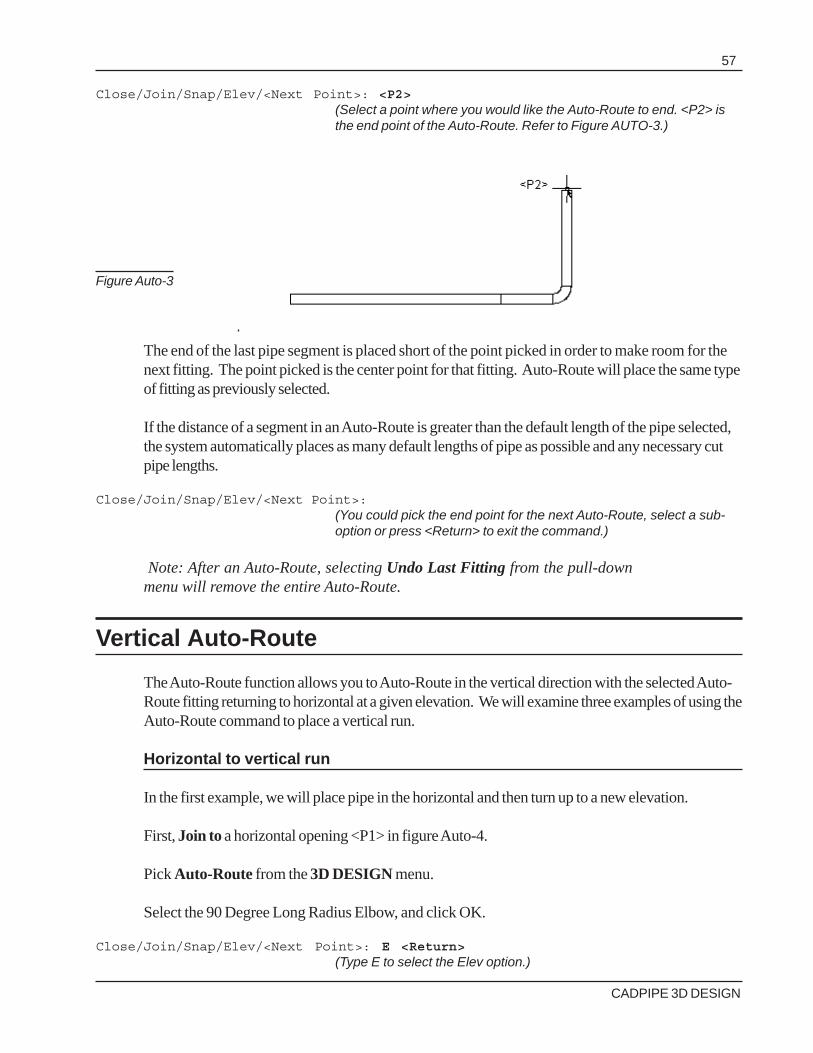
CADPIPE 3D DESIGN
57
Close/Join/Snap/Elev/<Next Point>: <P2>(Select a point where you would like the Auto-Route to end. <P2> isthe end point of the Auto-Route. Refer to Figure AUTO-3.)
The end of the last pipe segment is placed short of the point picked in order to make room for thenext fitting. The point picked is the center point for that fitting. Auto-Route will place the same typeof fitting as previously selected.
If the distance of a segment in an Auto-Route is greater than the default length of the pipe selected,the system automatically places as many default lengths of pipe as possible and any necessary cutpipe lengths.
Close/Join/Snap/Elev/<Next Point>:(You could pick the end point for the next Auto-Route, select a sub-option or press <Return> to exit the command.)
Note: After an Auto-Route, selecting Undo Last Fitting from the pull-downmenu will remove the entire Auto-Route.
Vertical Auto-Route
The Auto-Route function allows you to Auto-Route in the vertical direction with the selected Auto-Route fitting returning to horizontal at a given elevation. We will examine three examples of using theAuto-Route command to place a vertical run.
Horizontal to vertical run
In the first example, we will place pipe in the horizontal and then turn up to a new elevation.
First, Join to a horizontal opening <P1> in figure Auto-4.
Pick Auto-Route from the 3D DESIGN menu.
Select the 90 Degree Long Radius Elbow, and click OK.
Close/Join/Snap/Elev/<Next Point>: E <Return>(Type E to select the Elev option.)
Figure Auto-3

CADPIPE 3D DESIGN
58
Enter new Elevation <Current = 1'-6">: 3'(Enter the ending elevation of the pipe run.)
Close/Join/Snap/Use Current/<Elevation Point>:<P2>(Pick the point at which the pipe run turns up. This point is the centerof the elbow and establishes the center point of the second straightrun. The selection determines the point’s position in the x,y plane.)
Vertical run
In the next example, we will place a fitting and run vertical pipe.
First, Join To a horizontal opening.
Pick Auto-Route from the 3D DESIGN menu.
Select the 90 Degree Long Radius Elbow, and click OK.
Close/Join/Snap/Elev/<Next Point>: E <Return>(Type E to select the Elev option.)
Enter new Elevation <Current = 1'-6">: 5'<Return>(Enter the ending elevation of the pipe run.)
Close/Join/Snap/Use Current/<Elevation Point>: U <Return>(Type “U” to select the “Use Current” option. This selects the currentpoint (the exit end of the horizontal pipe) as the point at whichthe run turns up in Figure AUTO-5.)
Figure Auto-4

CADPIPE 3D DESIGN
59
Vertical to horizontal run
In our final example, we will place vertical pipe, return to the horizontal and place horizontal pipe.
First, Join To a vertical opening.
Pick Auto-Route from the 3D DESIGN menu.
Select the 90 Degree Long Radius Elbow, and click on “Ok”.
Enter Ending Elevation <Current = 1'-6">: <Return>
Close/Join/Snap/Elev/<Next Point>: E <Return>(Type E to select the Elev option.)
Enter new Elevation <Current = 1'-6">: 5'<Return>(Enter the ending elevation of the pipe run.)
Close/Join/Snap/Elev/<Next Point>: (Pick an end point (<P2>) in the x,y plane for the final horizontal run. From the“Select Angle” dialog box, pick the new horizontal direction, 0 degrees to theright. Refer to Figure Auto-6.)
Figure Auto-5
Figure Auto-6

CADPIPE 3D DESIGN
60
Figure Auto-8
Join
The Join option joins the Auto-Route to an existing pipe or fitting. Select Join, by typing J <Re-turn>. You will see the following:
Pick Pipe/Fitting to Join to:
When you select the fitting or pipe to which to join, the pipe and fittings needed for the Auto-Routeare drawn automatically (see Figure Auto-7).
The Join function will work in the horizontal and vertical directions. In the horizontal, the pipe orfittings must be at the same elevation. In the vertical, the Join function will work only when Auto-Route is selected while a pipe or fitting is in vertical mode and the connecting pipe or fitting is linedup in such a way that they will connect (see Figure Auto-8).
Figure Auto-7

CADPIPE 3D DESIGN
61
Snap
The Snap option is used in conjunction with the Join option to allow you to auto-route andconnect fittings at different elevations when more that one 90-degree turn is needed. When youselect Snap by typing S, the following system prompt will appear.
Pick Pipe/Fitting to Snap to:
Any of the AutoCAD SNAP modes can be used to snap a fitting. The Snap option will position theend of the first auto-route the correct distance from the fitting so you can then select Join, pick thefitting, and complete a second auto-route that will turn and join to the fitting. The following examplewill demonstrate how to use the Snap option.
In Figure Auto-9, we have a pump with a flange connection on one nozzle. We want to connect thepipe fitting at location <P1>, which has an elevation of 6’ with the flange connection at the top of thetank at location <P2>, which has an elevation of 2’-11.3100”. From the pipe at location <P1>,select Auto-Route. After you select the fitting to use in the Available Fittings for Auto-Routedialogue box (see Figure Auto-2), the following prompt will appear.
Close/Join/Snap/Elev/<Next Point>:
Type S to select the Snap option. The following system prompt will appear.
Pick Pipe/Fitting to Snap to:
Because we want to connect the flange on the pump, select the center ring on the flange (see Figure4-9).
Figure Auto-9

CADPIPE 3D DESIGN
62
Figure Auto-10
The system will auto-route the pipe to a location above the flange connection. The location that thesystem selects to end the pipe leaves enough room for another elbow to turn down and join to theflanged fitting (see Figure Auto-10).
The system will remain in the Auto-Route command and repeats the prompt.
Close/Join/Snap/Elev/<Next Point>:
Here you would select Join by typing J. Select the center ring of the flange again (see Figure Auto-10). The system will automatically turn an elbow down and connect pipe to the flange on top of thepump (see Figure Auto-11).

CADPIPE 3D DESIGN
63
Figure Auto-11
Close
The Close option will end the auto-route at a selected point and quit the Auto-Route function.When you select Close by typing C, the system will prompt you.
Elev <Pick end point of run>:
Any of the AutoCAD SNAP modes can be used to pick the end point. The important differencebetween the Close option and others is that the pipe will end exactly at the point selected withoutleaving room for another turning fitting and then quit the Auto-Routecommand.
Multiple Auto-Route Pipe Run
You can use a combination of Auto-Route techniques to draw a complex pipe run, which willrequire using several of the Auto-Route suboptions together; however, it is suggested when creatingmore complicated piping runs to use the Routing Line Command. Thiscommand is discussed in Chapter 4.

CADPIPE 3D DESIGN
64
COLLISION CHECKING
CADPIPE provides you with two collision checking features that will alert you to possible interfer-ence problems on your drawing. The interactive Collision Checking can be activated at any timeduring the drawing session. When activated, the system alerts you to interference between theobject you are placing and any 3D object on the drawing.
With Collision Checking on, the system takes an instant longer to place fittings. This delay occursbecause the system must search the drawing database to see if there are any interfering objectsbefore it places each piece. For this reason, CADPIPE allows you to toggle collision checking onor off, so that you can use it only when drawing in an area that presents potential interferenceproblems.
The Batch Collision Checking feature can be activated after the drawing is completed andsearches and highlights any interference problems on the drawing, allowing you to correct theproblems before the drawing is issued.
Interactive Collision Checking
To activate collision checking, select Collision Check from the 3DDESIGN menu.
When the Collision Checking toggle is on, the system automatically checks for any interferenceproblems with any 3D object on the drawing and alerts you when a fitting is placed which causes acollision. The colliding objects changes color and a Collision Alert box appears (see FigureCheck-1).
Figure Check-1

CADPIPE 3D DESIGN
65
View Collision
The View Collision option opens a View Entities dialog box, with the collision isolated (see FigureCheck-2).
Using the View Collision dialog box, you may change views of the collision, zoom in or out, rotatethe view up or down or right or left, and do an automatic HIDE.
Selecting “Ok” returns you to the drawing and Collision Alert box.
FIgure Check-2
Query Pipe
Selecting Query Fitting.... brings the Collision Query dialog box to the screen. This box containsthe dimensional data about the collision. The size, top and bottom elevation of each object incollision is listed. The distance and direction to correct the problem is calculated (see FigureCheck-3).

CADPIPE 3D DESIGN
66
When you are finished viewing the collision information, select “Ok.” This returns you to theCollision Alert box and allows you to Continue to draw and do nothing about the collision, or toReject the last piece of pipe or fitting drawn, so that you can avoid the collision.
Select Reject to remove the last drawn pipe or fitting that collided.
Since you know the amount needed to clear the interference, you can select a fitting to avoid thecollision.
Collision Checking can be activated at any time and will detect collisions in any view with any objectconstructed with AutoCAD 3D faces. If you receive coordination drawings from other trades andthey are using AutoCAD in 3D, CADPIPE 3D DESIGN will detect interference with any 3Dobjects provided that they are constructed with 3D faces.
Figure Check-3
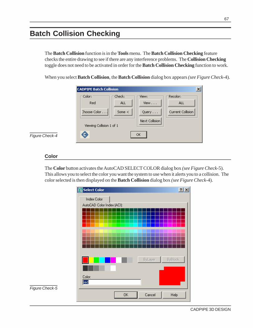
CADPIPE 3D DESIGN
67
Figure Check-5
Batch Collision Checking
The Batch Collision function is in the Tools menu. The Batch Collision Checking featurechecks the entire drawing to see if there are any interference problems. The Collision Checkingtoggle does not need to be activated in order for the Batch Collision Checking function to work.
When you select Batch Collision, the Batch Collision dialog box appears (see Figure Check-4).
Color
The Color button activates the AutoCAD SELECT COLOR dialog box (see Figure Check-5).This allows you to select the color you want the system to use when it alerts you to a collision. Thecolor selected is then displayed on the Batch Collision dialog box (see Figure Check-4).
Figure Check-4

CADPIPE 3D DESIGN
68
Check
Under the Check box, the commands All and Some are found. The All button tells the system tocheck the entire drawing (all displayed layers) for interference. The Some button allows you tochoose a window to check for interference. When you select Some the following system promptappears.
Select objects:
You may select any objects you wish by picking individual objects or using any of the AutoCADWINDOW options. When you finish selecting objects or selecting a window, the system dashesthe objects selected and again prompts you.
Select objects:
When <Return> is pressed, the system checks for collisions, while the following appears on thecommand line.
Checking for collisions among XX items.
You will also see the percentage of the area or drawing that has been checked. This numbercontinues to be updated until it reads 100% done. It also gives you the number of collisions thatwere found, while changing the color of the items on the screen to the selected Color.
The larger the drawing area you are checking, the longer the system will take to process the infor-mation.
View
The View box on the Batch Collision dialog box contains three options.
ViewThis option works the same as the View option in the Interactive Collision Checking mode.When selected, it changes the view and brings up the View Collision dialog box (see FigureCheck-2). All of the options on this box were explained in the section on Interactive CollisionChecking.
Note: You may leave the Batch Collision command at any time to correct an interferenceproblem. The system will remember all remaining collisions when you return to the BatchCollision command.

CADPIPE 3D DESIGN
69
QueryThe Query option, like the View option, works in the same manner as explained in the section onInteractive Collision Checking.
NextThe Next option zooms to the next collision found, and allows you to View or Query it. Thisprocess is repeated as long as there are more collisions to check.
Recolor
The options found under the Recolor box, All and Current, are used to return the items found incollision to their original color. This can be done by selecting All before you exit the Batch Colli-sion function, or Current if you wish to make adjustments to each collision consecutively. Thisfunction is useful if there are a large number of collision problems to address. The color change willremain until the All or Current button is activated.
Note: The system creates a layer called COLLISION in your drawing whenever CADPIPE 3DDESIGN is initialized. This layer is used with the View option to display the colliding objects.This layer should not be turned off or frozen.

CADPIPE 3D DESIGN
70
EDIT TOOLS
The Standard AutoCAD commands can be used to edit CADPIPE items. The CADPIPE Editfunctions are useful because they ignore any entity that is not a fitting or object drawn usingCADPIPE. These functions are found on the Edit toolbar and in the Editing Tools sub-menu onthe Tools pull-down menu.
3D DESIGN Move
This command allows you to move pipe, fittings, CADPIPE items, or any CADPIPE architecturalitem. The 3D Design Move command only recognizes pipe, fittings, 3D Design items, andCADPIPE architectural items. All other items in the drawing are ignored. When you use 3D DesignMove, the following prompt appears.
Select objects:
You may choose to select individual objects or use any of the AutoCAD WINDOW modes toselect objects. When you have finished selecting objects and press Enter, the following promptappears.
Base point of displacement:
Select a base point.
Second point of displacement:
Select a location for the move, and the objects will move. The system displays thenumber of CADPIPE objects moved on the command line.
Note: If you wish to move only text, use the Shift-Ctrl-right click keystroke combination andselect Move Grouped Item from the pop-up menu.

CADPIPE 3D DESIGN
71
Figure Edit-1
3D DESIGN Copy
This command works in the same manner as 3D DESIGN Move, allowing you to copy pipe,fittings, and CADPIPE Structural items. The CADPIPE Copy command differs from theAutoCAD Copy command in that it copies all of the associated properties and information alongwith the visible pipe, fitting, or CADPIPE object. In addition, the Copy command only recognizespipe, fittings, and Structural objects drawn using the CADPIPE commands. Any other objects onthe drawing are ignored. The prompts for Copy are the same as those for Move, with the addi-tional copy Multiple option. This option works in the same manner as the AutoCAD Copycommand (see AutoCAD manual COPY command).
Be sure to Join to the pipe or fitting that has been moved or copied if you want to continue drawingfrom that pipe or fitting.
3D DESIGN Erase
This command allows you to erase CADPIPE items. The Erase command only recognizes pipe,fittings, and Structural items drawn using CADPIPE commands. Any other objects on the drawingare ignored. The prompts for the Erase command are the same as those for the Move command.
Note: If you want to delete only text, use the Shift-Cntrl-right click keystroke combinationand select Erase Grouped Item from the pop-up menu. Or type ee at the command prompt.
When using 3D DESIGN Erase, and other CADPIPE items aside from pipe and fittings areselected, the Erase CADPIPE 3D Items dialog box appears (see Figure Edit-1). This allowsyou to erase, move or copy only pipe and fittings rather than all CADPIPE items.

CADPIPE 3D DESIGN
72
3D Design Mirror
The 3D Design Mirror command is found on the Editng Tools sub-menu on the Tools pull-down. This command enables you to mirror objects around a mirror line, which you define with twopoints. Mirroring works in any plane parallel to the XY plane of the current UCS. When you selectMirror Fitting(s) from the menu you are prompted to select the object to be mirrored.
select fittings to mirror:
After choosing an object, you are then prompted to select two points to create the mirror line (seeFigure Edit-2).
select objects: specify first point of mirrorline:
specify second point of mirrorline:
The next prompt allows you to either delete or retain the original objects.
Delete source objects? [Yes/No] <N>:
Type Y to delete the source objects (see FigureEdit-3).
CADPIPE 3D DESIGN
Figure Edit-2
Figure Edit-3

CADPIPE 3D DESIGN
73
Or N to retain the source objects (see Figure Edit-4).
3D Design Rotate
The 3D Design Rotate command is found on the Tools pull-down menu. This command enablesyou to rotate objects by choosing a base point and a relative or absolute rotation angle. When youselect 3D Design Rotate from the menu the following prompt appears.
Select fittings to rotate:
After choosing an object, you are then prompted to select the base point for the rotation (seeFigure Edit-5).
Select objects: specify base point:
The next prompt allows you to select the rotation angle (see Figure Edit-6).
Figure Edit-5
Figure Edit-4

CADPIPE 3D DESIGN
74
3D Design Rotate 3D
The 3D Design Rotate 3D command is found on the Tools pull-down menu. This commandenables you to rotate objects in 3D around a specified axis. You specify the axis of rotation usingtwo points; an object; the X, Y, or Z axis; ro the Z direction of the current view. When you select3D Design Rotate 3D from the menu, the following prompt appears.
Select fittings to rotate:
After selecting an object, you are then prompted to determine the axis for the rotation.
Specify first point on axi or define axis by [Object/Last/View/Xaxis/Yaxis/Zaxis/2points]:
The Object option aligns the axis of rotation with an existing object.
Figure Edit-6
Figure Edit-7
Specify rotation angle or [Reference]:
CADPIPE rotates the object (see Figure Edit-7).

CADPIPE 3D DESIGN
75
The Last option uses the last axis of rotation.
The View option aligns the axis of rotation with the viewing diretion of the current viewport thatpasses through the selected point.
The 2points option uses two points to define the axis of rotation.
After choosing an axis for the rotation, CADPIPE will prompt you to select a rotation angle and willrotate the object.
For more information about rotating in 3D please refer to the ROTATE3D section in your AutoCAD manual underCommand Reference.
Move Last Fitting
The Move Last Fitting Command is a quick way to move the last pipe or fitting drawn. As soonas you place a fitting or piece of pipe, you can select Move Last and pick a new placement pointfor the fitting.
Note: Be sure to Join to the pipe or fitting that has been moved if you want to continuedrawing from that pipe or fitting.
3D DESIGN Query
The 3D DESIGN Query command is in the CADPIPE Tools menu. This command queries anyCADPIPE object and lists important information about that object. When you select 3D DESIGNQuery from the menu, the system prompts you with the following.
CADPIPE Item to Query:
Select the pipe, fitting or CADPIPE item about which you want information. You can only select oneitem at a time. The information will be displayed in the 3D DESIGN Query dialog box. Theinformation will include the type, size, material, connection, elevation and weight information aboutthat fitting or item (see Figure Edit-8).
In the 3D DESIGN Query box are five options that can be activated to place the text informationin the drawing. The “Text Options” button controls how the text appears on the drawing.

CADPIPE 3D DESIGN
76
Figure Edit-8
Place Size
When you select this button, the system prompts you for a location for the size text.
Pick Point For Size Text:
Pick a point on the drawing, and the size text is placed. This text becomes part of the fitting oritems and will move, copy or erase with it. The text is oriented in the direction of the pipe, fitting orCADPIPE item.
Place Length
When you select this button, the system prompts you for a location at which to place the length texton thedrawing.
Pick Point For Length Text:
Pick a point on the drawing, and the length text is placed. This text becomes part of the pipe, fittingor items, and will move, copy or erase with it. The text is oriented in the direction of the pipe, fittingor CADPIPE item.
Place Slope
When you select this button, the system prompts you for a location for the slope text.

CADPIPE 3D DESIGN
77
Pick Point For Slope Text:
Pick a point on the drawing, and the slope text is placed. This text becomes part of the fitting oritems, and will move, copy or erase with it. The text is oriented in the direction of the pipe.
Place Line Designation
When you select this button, the system prompts you for a location for the line designation text.
Pick Point For line designation Text:
Pick a point on the drawing, and the line designation text is placed. This text becomes part of thefitting or items and will move, copy or erase with it. The text is oriented in the direction of the pipe.
Place Description
When you select this button, the system prompts you for a detailed description of the item (seeFigure Edit-9).
Click the Use Fitting Name or Use Pipe Size and Name buttons to begin your description withthe item’s name or size, or you can enter your own text. CADPIPE prompts you to pick a point toplace the descriptive text. It is oriented in the direction of the pipe. This text becomes part of thefitting or items and will move, copy, or erase with them.
Place Elevation
When you select these buttons, the system prompts you for a location for the elevation text.CADPIPE can place the center, top or bottom elevation of the item.
Pick Point for elevation Text:
Pick a point on the drawing, and the elevation text is placed. This text becomes part of the pipe,fitting or item, and will move, copy or erase with it. The text is oriented in the direction of the pipeor CADPIPE item.
Figure Edit-9

CADPIPE 3D DESIGN
78
Insert Fittings and Valves
The Insert Fitting command allows you to insert fittings and valves into an existing run of pipe. IfSpec Check is on, the command matches the size, end type and rating with the pipe into which isinserted.
The Insert Fitting command is in the 3D DESIGN menu. When you select the Insert Fittingscommand from the menu, the Insert Justification dialog box appears (see Figure Edit-10).
This box lists the fitting insertion options: Left, Center, Right and Aligned.
When you select Left, Center or Right, you will see the following prompt
Pipe to Insert into (at insertion point):
Pick the point on the pipe where the fitting will be inserted. The Left, Center, and Right optionsinsert the fitting or valve, placing the left side, center, or right side of the item, at the point picked.After you select the insertion point for the fitting, the system highlights the pipe and display theFitting to Insert dialog box (see Figure Edit-11).
Figure Edit-11
Figure Edit-10

CADPIPE 3D DESIGN
79
Figure Edit-13
Figure Edit-12
This dialog box contains a list of the available fittings. Select a fitting and click on “Ok”Next, you will see the Select Angle dialog box (see Figure Edit-12).
Select the rotation angle of the secondary branch. Selecting 0 degrees always places the branch tothe right side of the pipe, 90 turns up, 180 turns to the left side and 270 turns down.
Remember: these angles are determined by the direction in which the pipe is drawn (see FigureEdit-13). If an item is inserted into pipe, these angles refer to the plan view AutoCAD directionangle.
If you select the Aligned option from the Insertion Justification box, the prompts are slightlydifferent. The Aligned option aligns the fitting with another pipe or fitting in another run of pipe.This option is useful for inserting fittings with a secondary branch such as a Tee. When you selectAligned, the following prompt appears.

CADPIPE 3D DESIGN
80
Pipe to Insert into:
Select the pipe in which you want to insert a fitting. The system highlights the pipe and display theFitting to Insert dialog box (see Figure Edit-11). If you select a Tee, Cross or Reducing tee fromthe dialog box, you will see the following prompt:
Pick Pipe/Fitting to Align with:
Select the existing fitting on the other run with which you want to align the fitting you are placing.
If the fitting being placed must be rolled in order to align with the existing fitting, the Select Anglebox appears (see Figure Edit-12). Select a rotation angle for the secondary branch.
When the fitting is inserted into the pipe using any justification option, CADPIPE automaticallydivides the pipe and update the entity data for the two pieces of new pipe. These will have thecorrect dimensions, taking into account the connection ends of the inserted fitting.
Inserting a Valve
When you select a valve, the Valve Type dialog box appears (see Figure Edit-14).
Select a valve type and valve pattern. If Spec Check is on, your choices are restricted to those inthe material specification. If you select an out-of-spec valve type or pattern, the program tells youto turn Spec Check off before you try to place the item.
Figure Edit-14

CADPIPE 3D DESIGN
81
Once you have selected the valve, the Select Angle dialog box appears, allowing you to rotate thevalve stem before inserting it. The Select Angle dialog box only appears if the selected valve has avalve stem.
Fitting Conversion
The Fitting Conversion function is in the Tools pull-down menu. This function converts any pipeor fittings between the three CADPIPE drawing modes. When you select Fitting Conversion, thefollowing prompt appears.
Select objects:
At this prompt you can use any if the AutoCAD WINDOW commands to select the pipe or run ofpipe to convert. After making your selection, press Enter and the Convert Pipe/Fittings To dialogbox appears (see Figure Edit-15). Select the drawing mode you wish to convert your pipe orfittings to and click OK. CADPIPE automatically converts those fittings you have selected.
Stretch Pipe
CADPIPE 3D Design has the ability to stretch pipe. This feature utilizes the AutoCAD STRETCHCommand. It enables the user to stretch a piece of pipe to any desired length and still maintain itsintelligence.
Typical Command Sequence
An example of using the stretch pipe command is demonstrated below.
Type ‘stretch’ at the command line.
Command: stretch <Return>
Select objects to stretch by crossing-window or crossing-polygonSelect objects:
(Draw a window around the piece of pipe. See Figure Edit-16)
Figure Edit-15

CADPIPE 3D DESIGN
82
Figure Edit-17
Figure Edit-16
Select objects: Specify opposite corner: 3 foundSelect objects: <Return>Specify base point or displacement: <P1>
(Select the end of the pipe that will be stretched. See <P1> in Figure Edit-17)

CADPIPE 3D DESIGN
83
Figure Edit-18
Specify second point of displacement: <P2>(Simply stretch the pipe to the desired length. <P2> in Figure Edit-18)
When the second point is picked, CADPIPE redraws the pipe, matching the length it was stretched,as shown in Figure Edit-19.
Figure Edit-19

CADPIPE 3D DESIGN
84 EDIT-15
ISOLATE
The ISOLATE command on the Tools Menu allows you to isolate a pipe run or any items youchoose from the rest of your drawing. When you select ISOLATE the Isolate Pipe/Fittings dialogappears (see Figure Edit-20).
Dgitize Run
The Digitize Run button allows you to pick any pipe run on your drawing. After clicking the buttonyou are prompted to select a run. Simply click on any part of a pipe run and CADPIPE brings up aView Entities Box with an isolated view (see Figure Edit-21).
Figure Edit-20
Figure Edit-21
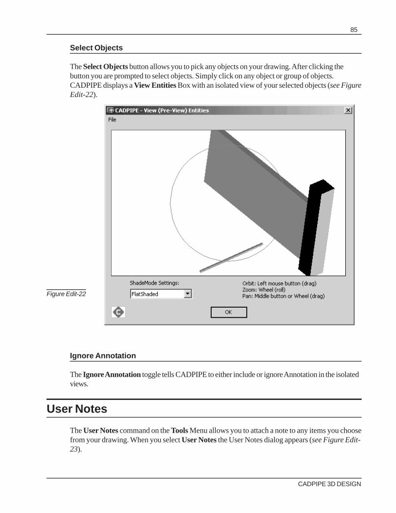
CADPIPE 3D DESIGN
85
Select Objects
The Select Objects button allows you to pick any objects on your drawing. After clicking thebutton you are prompted to select objects. Simply click on any object or group of objects.CADPIPE displays a View Entities Box with an isolated view of your selected objects (see FigureEdit-22).
Ignore Annotation
The Ignore Annotation toggle tells CADPIPE to either include or ignore Annotation in the isolatedviews.
User Notes
The User Notes command on the Tools Menu allows you to attach a note to any items you choosefrom your drawing. When you select User Notes the User Notes dialog appears (see Figure Edit-23).
Figure Edit-22

CADPIPE 3D DESIGN
86
Figure Edit-23
Digitize Run
The Digitize Run button allows you to pick any pipe run on your drawing. After clicking the buttonyou are prompted to select a run. Simply click on any part of a pipe run and press Enter. The UserNotes dialog appears allowing you to enter a note (see Figure Edit-24).
In this example, we’ve entered the note: User Note test 2 Digitize Run. Press the Add Notebutton and now this note is attached to the all pipe and fittings on the selected run. Our note nowappears in the Query dialog, when any pipe or fitting from the run is queried (see Figure Edit-25).
Figure Edit-24

CADPIPE 3D DESIGN
87
Select Objects
The Select Objects button allows you to pick any objects on your drawing. After clicking thebutton you are prompted to select objects. Simply click on any object or group of objects andpress Enter. The User Notes dialog appears allowing you to enter a note (see Figure Edit-26).
Figure Edit-25
Figure Edit-26

CADPIPE 3D DESIGN
88
In this example, we’ve entered the note: user note test 1. Press the Add Note button and now thisnote is attached to the pipe we selected. Our note now appears in the Query dialog, when the pipeis queried (see Figure Edit-27).
BOM Tag
The BOM Tag function is found on the Tools pull-down menu. This function allows you to markany non-CADPIPE item and enables it to be included in your BOM reports. When you select thiscommand you are prompted to pick the object.
Select objects:
At this prompt select the item to place a BOM Tag, press Enter, and the CADPIPE BOM Tagdialog box pops up (see Figure Edit-28).
From here you can set a BOM Name for the object and the Line Number, Material Spec,Database, Size, Rating, Schedule, Manufacturer, End Types, and Weight information for theobject. This information appears in the BOM report.
You can also press the Same As. . . button and select an existing object on your drawing.CADPIPE matches the BOM tag with your selected object.
Figure Edit-27

CADPIPE 3D DESIGN
89
Figure Edit-28

CADPIPE 3D DESIGN
90
ISO DRAWINGSCADPIPE 3D DESIGN automatically produces Isometric drawings from your plan view projec-tions. Using the Iso Pipe and Label functions, you can produce an ISO drawing for fabrication ofyour piping system. The Iso Pipe command creates an isometric view of any section of pipewithout having to change your AutoCAD VIEWPORTS or USER COORDINATE SYSTEM.Once the Iso drawing is created, the CADPIPE Label function automatically labels the drawing andproduces a Bill of Materials of all cut lengths of pipe and fittings.
Iso Pipe
The Iso Pipe command allows you to create a quick ISO-view of any section of pipe while in planview, without having to rotate or change AutoCAD VIEWPORTS. When you select Iso Pipe fromthe Tools menu, the Isometric CADPIPE 3D dialog box appears (see Figure ISO-1).
This box allows you to define the type of projection you want, Top, Front,or Right View and toselect a scale factor for the ISO-view.
Projection
The image in the dialog box shows an ISO-view of a cube with three labeled projection planes.You can select Top, Front, or Right to tell CADPIPE that your view (the one of which you want tocreate an ISO-view) is the top, front, or right projection plane. Recall that the AutoCAD worldplan view (the X-Y plane) is the true plan view for all CADPIPE piping, since the turning commands(left, right, up, down) are all relative to the AutoCAD world coordinate system. This means theAutoCAD world plan view is the basis for the true Top projection of the ISO-view. This is whyCADPIPE defaults to the Top projection in the dialog box.
Edit ISO-1

CADPIPE 3D DESIGN
91
Figure ISO-2
Scale
This option allows you to scale the ISO-view that will be created. A factor of 1.00 keeps the viewthe same scale as the plan view.
Spool Sheet Number
CADPIPE automatically creates a name for the ISO drawing. The name consists of the initials SPand a three digit number. This name is used for the report that is created for the spool sheet. Afterselecting the view, scale, name, and then “Ok”, you will see the following prompts:
Entities to Isometrically Project:
Select objects:
To select the objects to include in the ISO-view, you can use any AutoCAD WINDOW selectionset (see AutoCAD manual Select Set Windows). After selecting the pipe and fittings, the followingprompt appears:
Location for Isometric Projection:
Select a location for the ISO-view, and the system will create an ISO-view of the selected pipe andfittings. The ISO-view is a 2D isometric drawing, not a true isometric view of a 3D representation(see Figure ISO-2). The ISO pipe and fittings are drawn on the current layer in the same color asthe 3D pipe and fittings.
If you do not like the location of the ISO-view, you can select Move Last Fitting(s) from the 3DDESIGN menu (before you do any other commands), and drag the ISO-view to the desiredlocation.

CADPIPE 3D DESIGN
92
ISO Checkmarks
When you create an ISO, CADPIPE automatically places a check mark and spool number on eachpiece of pipe or fitting to be included in the ISO. These check marks and spool numbers willappear on the plan view of your drawing. They are placed on layer SPOOL_CHECKMARK sothat you can turn them on or off. This ensures that no pipe or fittings are missed when you makeyour spool drawings for fabrication. It also serves as a reference from the spool sheet back to theplan view drawing.
Label Function
The Label Function commands allow you to label your ISO drawing and generate a summary of thelabels. They are located on the Label Function sub-menu on the Tools pull-down menu.
Note: The Label Function can be used on either an isometric drawing generated by Iso Pipeor on the original 3D piping design.
Placing Labels
When you use the Label Function options, the system automatically labels all pipe and fittings witha balloon, leader, arrow and number. As you pick pipe or fittings, the number automatically incre-ments, while all like pipe and fittings receive the same balloon number (see Figure ISO-4).
When you select Do Labels from the menu, the following system prompt appears.
Pipe/Fitting to Label:
Select the pipe or fitting at the location to which you want the arrow and leader to attach. It is bestto zoom up when you do this. When you select the pipe or fitting, the following prompt appears(see Figure ISO-3).
Abort/Last Delta/New Hinge/<Bubble location>:
You can pick the location for the balloon (see Figure ISO-3), or type the first character of an optionto select the other commands in the prompt.
The Last Delta option creates a leader line the same length and angle as the lastleader line created. This option enables you to easily create a neat, uniform array of bal-loons and leader lines.
The New Hinge option moves the point of connection of the leader line to a newlocation along the item picked.

CADPIPE 3D DESIGN
93
Figure ISO-3
The balloon, arrow and text are sized according to the settings in the Label Function (see FigureISO-4).
Figure ISO-4

CADPIPE 3D DESIGN
94
Auto Labeling
A whole run of pipe, or any combination of pipe and fittings, can be selected together for labeling.Instead of placing each balloon separately, you pick all the items to be labeled, and CADPIPEprompts you to label each item in the order drawn.
Select the Auto Labeling command from the CADPIPE Tools menu. Then select all the items tobe labeled. You can use AutoCAD’s Window command or pick each item individually. CADPIPEwill select the first piece in the set:
(Pipe)Undo/Skip/Quit/Last Delta/New Hinge/<Bubble location>:
A description of the current item selected will appear in parenthesizes at the beginning of the promptline. This description will change to reflect the current item selected as the system selects the itemsconsecutively.
You can pick a balloon location immediately, change the point of the connection of the leader line byusing New Hinge, or Skip the selected piece, allowing the system to move automatically to the nextpiece. The Last Delta option will create a leader line the same length and angle as the last leaderline created. You can also Undo the last balloon placed or Quit to exit the Auto Labeling com-mand.
Move/Erase/Print Label
If you want to move a label, pick Move Label from the Label Function menu, digitize the labeland pick its new location. If you want to move the point of connection of the leader line, use theNew Hinge option in the prompt line. Abort will exit the command.
Select Erase Label from the Label Function menu to erase the leader line and balloon with onepick.
You can print the labels for the pipe and fittings shown on your ISO drawings using the Print Labelcommand from the Label Function menu. The labels contain the spool number, the label number,size, end type, rating, schedule and material specification.
Label Options
Text SizeYou can set the text size for the label. This setting sets the size of the balloon number, which in turnaffects the size of the balloon.
Text StyleWhen you select Text Style, the system displays the standard AutoCAD text font box, allowingyou to specify a font for the label numbers (see Figure ISO-5).

CADPIPE 3D DESIGN
95
Figure ISO-6
Figure ISO-5
Next Label#CADPIPE keeps track of the next label number you place. When you open a session, this numberis automatically set for you. When you select Next Label #, the following system prompt appears.
Next Bubble Number <X>:
At this prompt you can enter a new number.
Undo Last LabelThis option will undo the last label placed. The label number is updated when this is done. Toresume placing labels, select Do Label from the menu.
New Session
This option begins a new label session. When you select New Session, you can begin to pick thepipe and fittings to label.
Open Session
When you select Open Session, the Restore Label Session from a File dialog box appears (seeFigure ISO-6). You can select and recall a label session from the list. This sets the parameters foryour labels and allows you to continue to label your drawings.

CADPIPE 3D DESIGN
96
Save Session
This option saves a current label session. When you do this, the system remembers all label optionparameters that are set, and the last label number. You can then recall this session using the OpenSession command at a later time. When you select Save Session, the Save Label Session to aFile dialog box appears, allowing you to enter a save name.
Report
The Label Report option generates a report of your label session. When you select Label Re-port from the Label Function menu, the 3D DESIGN Label Report dialog box appears (seeFigure ISO-7).
This dialog box allows you to select a Print option (which prints the report), a To File option (savethe report to a file), or the To Clipboard option (copies the report text places it onto your comput-ers clipboard, allowing you to paste the text elsewhere). If you select the To File option, thesystem displays the Save Label Report to a File dialog box (see Figure ISO-8).
The report file is a text file which can be imported to word processing and spread sheet programs,or modified for use in other documents.
Figure ISO-7

CADPIPE 3D DESIGN
97
Figure ISO-8
Place report on drawing
To place the report on the drawing, save it to a file and select the AutoCAD MTEXT command bytyping MTEXT at the command prompt. For details and how to use the MTEXT command, referto your AutoCAD manual.
Exit
When you select Exit to leave a labeling session, the Label Session Not Saved dialog box mayappear (see Figure ISO-9). This box warns you that your label session is not saved. You do notneed to save the session unless you want to come back and generate a report or add more labels.
You can also label the 3D model itself without generating a single-line ISO. Simply, change to anisometric view, set UCS to View and label your design directly.
Figure ISO-9

CADPIPE 3D DESIGN
98
CADPIPE AUTO-ISO Program
If you want to generate an even more detailed single-line ISO from your 3D drawing, you cancreate a Universal Data Exchange (UDE) file in 3D DESIGN, and then use the AUTO-ISO com-mand in the CADPIPE ISO program to create an ISO drawing. You must have the CADPIPE ISOprogram to use CADPIPE AUTO-ISO.
Creating the Universal Data Exchange (UDE) file
To create a UDE file (sometimes referred to as a connectivity file), select UDE Out from the3DDESIGN menu and you will see the following prompt:
Pick Run to Process:
Digitize anywhere along a run. When the run has been selected, the UDE File dialog box appears.Type in a name for the UDE file and then click on “Ok.” Sections of the run are highlighted asCADPIPE processes all the items on it.
The file is automatically saved to a UDE directory (\CTY), which is created off your parentCADPIPE directory. This is where the AUTO-ISO program will look for .UDE files.
When you are returned to your drawing, you have the option to pick another run to process orpress <Return> to exit the command.
You are now ready to run the CADPIPE AUTO-ISO program. Refer to the AUTO-ISO docu-mentation in the CADPIPE ISO manual.

CADPIPE 3D DESIGN
99
REPORTS
CADPIPE 3D DESIGN can generate reports or bills of materials of all pipe and fittings included onthe drawing. These reports are useful for shipping, estimating, fabrication, and ordering equipment.
Pipe and Fittings Reports
Pipe and fitting reports are automatically generated from the drawing and contain important informa-tion for shipping and estimating a job, including the following: pipe size, rating/schedule, materialspecification, Line Designation, end types, and length.
Pipe Reports
Select Pipe Reports from the Tools menu, and a 3D Report Generator dialog box appears.Options for the Report Type (Pipe Report, Fitting Report, and Valve Report) are available (seeFigure Report-1).
Select the type of report and click on “Ok.” The system automatically generates a report. You alsohave the option to specify a Job Description for your report. The Job Description can be anumber or title and will appear on the report.
Note: Only pipe or fittings on active (turned on) layers will be reported. With this feature youcan selectively turn layers on or off to report only selective piping systems.
The following are samples of pipe, fitting and valve reports.
Figure Report-1

CADPIPE 3D DESIGN
100
Pipe Report
Fitting Report
Figure Report-2
Figure Report-3

CADPIPE 3D DESIGN
101
Valve Report
After generating a report, the options Print, To File, and To Clipboard are available. The Printoption sends the file to your printer. The To Clipboard option saves the report text to your comput-ers clipboard. The To File option saves the report to a file. When you select To File, the SaveReport to a File dialog box appears (see Figure Report-5).
Figure Report-4
Figure Report-5

CADPIPE 3D DESIGN
102
The report file is a text file with the .txt extension. The file name is limited to eight characters. Thereport file can be imported to word processing and spread sheet programs, and modified for use inother documents.
Place report on drawing
To place the report on the drawing, save it to a file and select the AutoCAD MTEXT command.
Type MTEXT at the command prompt.
Create a window large enough to contain the report file. Right-click in the window and selectImport Text from the menu.
Locate and select the Report file *.txt. Click on “Ok.” The text file will load into the designatedwindow.

CADPIPE 3D DESIGN
103
Section Views/SpoolingThe CADPIPE 3D Design Drawing Sheets menu contains commands associated with creatingDrawing Sheets, Layouts, Sections, and Spools.
Sheet Layout
CADPIPE provides direct access to some AutoCAD tools to help you set up layout sheets. TheSheet Layout sub-menu on the Drawing Sheets pull-down has three options for creating sheetlayouts: New Layout, New Layout with Wizard, and Manual Setup.
New Layout
The New Layout menu creates a new layout tab. The following message appears at the commandprompt.
Enter new Layout name <Layout#>:
Press Enter to use the name AutoCAD automatically assigns (inside the brackets on the commandline), or type a new name and then press Enter. The new layout sheet is created.
New Layout with Wizard
The New Layout with Wizard menu option brings up the AutoCAD Create Layout dialog box(see Figure Section-1). This dialog box contains a series of steps, taking you through the processof creating a new layout. You can choose to create a new layout from scratch or use an existinglayout template as a base for your new layout. CADPIPE provides several example title blocktemplates listed in the Create Layout dialog box.
Depending on which plotting device is currently configured, you can select a paper size from thoseavailable. You can select a predefined title block from a list and apply it to the new layout you arecreating. The Preview area displays a preview image of the title block you select.
When finished using the wizard to specify your layout settings, you can modify any of the settingsusing the Page Setup dialog box from within the new layout.

CADPIPE 3D DESIGN
104
Manual Setup
The Manual Setup menu option enables you to manually set up drawing sheets. When selected, itruns the AutoCAD MVSETUP command and displays the following prompt on the command line.
Enable paper space? [No/Yes] <Y>:
Selecting yes will create a new layout sheet and display the next prompt containing all the nessecaryoptions for you to create a new layout sheet.
Enter an option [Align/Create/Scale viewports/Options/Title block/Undo]:
Please refer to your AutoCAD manual and/or help files for more information on creating layoutsheets with these commands.
Section/Floor Plan Views. . .
The Section/Floor Plan Views. . . sub-menu on the Drawing Sheets pull-down contains twooptions for setting up and generating sections and plan views. They are: Setup/Generate andGenerate.
Figure Section-1

CADPIPE 3D DESIGN
105
Setup/Generate
The Setup/Generate menu option displays the Section / Floor Plan Views -- Setup dialog box.From this dialog box you can setup and generate multiple section views and floor plan views.
Section
Selecting the Section toggle in the Section / Floor Plan Views -- Setup dialog box activates theSection View options (see Figure Section-2).
Section NumberThis field allows you to create customized names/numbers for your section views. Type the name/number you wish to assign to the section. The text in this field appears on the section marks.
Text SizeThis field allows you to set the text size of the section marks that appear in your view.
Text StyleThis option allows you to set the text style of the section marks you are placing.
Figure Section-2

CADPIPE 3D DESIGN
106
Ref. DrawingThis field allows you to name a reference drawing for your section view.
Section Arrow StyleAllows you to choose the arrow style for the section marks that appear on your drawing (seeFigure Section-3).
Section View FromAllows you to pick the direction you want to view the section from.
Digitize AreaThis button allows you to digitize the area of the drawing that makes up your section view.CADPIPE automatically returns to the drawing and prompts you to select a first and second pointfor the section area.
Generate ViewWhile setting your section view parameters, this button is greyed out. It becomes active once theyare set, and you can use it to instantly generate your Setion View. CADPIPE prompts you to selectthe viewport in which the view will appear.
Creating Multiple ViewsCADPIPE gives you the ability to set up multiple section views from this dialog box. To do this, setall neccessary parameters for your first section view. Then click the OK button and CADPIPEclears the previous settings, allowing you to create another section view. Once you have created allsection views needed, they can be generated and accessed from the Section / Floor Plan Views --Generate View dialog box (see Figure Section-5).
Figure Section-3

CADPIPE 3D DESIGN
107
Figure Section-4
Floor Plan
Selecting the Floor Plan toggle in the Section / Floor Plan Views -- Setup dialog box activatesthe Floor Plan options (see Figure Section-4).
Floor Plan DescriptionThis field allows you to set a name for the floor plan. This description is listed in the Section / FloorPlan Views -- Generate View dialog box.
Upper ElevThis field allows you to enter the upper elevation for the floor plan clipping planes.
Lower ElevThis field allows you to enter the lower elevation for the floor plan clipping planes.
Digitize Elevations. . .This button allows you to digitize points on the drawing to indicate the upper and lower elvations thefloor plan clipping planes.

CADPIPE 3D DESIGN
108
Generate ViewWhile setting your Floor Plan parameters, this button is greyed out. It becomes active once they areset and you can use it to instantly generate your Floor Plan. CADPIPE prompts you to select theviewport in which the view will appear.
Creating Multiple Floor PlansCADPIPE gives you the ability to set up multiple plan views using this dialog box. To do this, set allneccessary parameters for your first Floor Plan. Then click the OK button and CADPIPE clears theprevious settings allowing you to create another Floor Plan. Once you have created all plan viewsneeded, they can be generated and accessed from the Section / Floor Plan Views -- GenerateView dialog box (see Figure Section-5).
Generate
The Generate menu option brings up the Section / Floor Plan Views -- Generate dialog box(see Figure Section-5). This dialog box displays a list of Section Views and Floor Plan views. If youhave not set up any views before selecting this option, the dialog box will be empty.
SectionThe Section toggle activates the Select Section View list allowing you to choose which sectionview you would like to generate. Simply highlight your chosen view and click the Generate Viewbutton. CADPIPE prompts you to select a viewport to place the view.
Digitize the viewport for the section view:
note: You should set up all your layout sheets and viewports prior to generating the section views.
Floor PlanThe Floor Plan toggle activates the Select Floor Plan View list allowing you to choose which floorplan view you would like to generate. Simply highlight your chosen view and click the GenerateView. . . button. CADPIPE prompts you to select a viewport to place the view.
Digitize the viewport for the section view:
Figure Section-5

CADPIPE 3D DESIGN
109
note: You should set up all your layout sheets and viewports prior to generating the floor plan views.
Delete View. . .The Delete View. . . button allows you to select either a section or floor plan view (depending onwhich list is active) and delete it. Highlight the view you wish to delete, click the Delete View. . .button, and the selected view is removed from the list.
Clear Clipping Planes
The Clear Clipping Planes command is located on the Drawing Sheets pull-down menu. Thismenu option removes all clipping planes set during the setup of section and/or floor plan views.
Spools
The Spools sub-menu on the Drawing Sheets pull-down contains two options for setting up andgenerating spools. They are: Setup and Generate.
Setup
The Setup menu option brings up the CADPIPE Auto-Spool -- Setup dialog box (see FigureSection-6). The Setup dialog box is where you will setup and manage your spools.

CADPIPE 3D DESIGN
110
Job NumberThe Job Number field allows you to attach a name to your spools.
Spool PrefixThe Spool Prefix field allows you to enter a prefix for your spools.
Spool NumberThe Spool Number field allows you to number each spool.
Digitize Items to Spool >The Digitize Items to Spool button allows you select the items to included in the spool. When thisbutton is pressed, the Setup dialog box disappears allowing you to select the items. You can useany standard AutoCAD selection set (window, crossing, remove, individual selection, etc) to pickthe items. When you have finished your selections, press enter and you will be returned to the Setupdialog box.
Display ColorThe Display Color area shows the color your selected spool items will appear. You can choose acolor by pressing the Select Color button and picking a color from the AutoCAD Select Colordialog box. The spooled items will only be this color while the spooling command is active, in orderto distinguish them from non-spooled items. You can choose the Spool Setup command at any timeand press the Digitize Drawing button to check what items in your drawing have already beenspooled.
Reserve Current SpoolThe Reserve Current Spool button saves your spool, allowing you to set up mutlitple spools forgeneration later.
Reserved Spool NumbersThe Reserve Spool Numbers field lists all the spools you have created and saved. It also lists thecolor of each spool under the Display Color heading. The total number of reseverd spools is listedbeneath the field. This funtions associated with this list allow you to highlight a spool from the list,select its highlight color, and/or delete reserved spools.
Highlight ColorThe Highlight Color area shows the color your selected spool will be highlighted when you clickthe Highlight Selected Spool button. You can choose a new color by pressing the Select Colorbutton and picking a color from the AutoCAD Select Color dialog box. The spooled items will onlybe this color while the Hightlight Selected Spool command is active in order to distinguish themfrom your other spools on the drawing.
Highlight Selected Spool >The Highlight Selected Spool button allows you to view the spool you have selected from theReserved Spool Numbers field. When pressed, CADPIPE returns to your drawing and highlightsthe selected spool. The highlight color is controlled in the Highlight Color area of the Auto-Spool -- Setup dialog box.

CADPIPE 3D DESIGN
111
Figure Section-8
Delete Selected SpoolThe Delete Selected Spool button allows you to remove any spool from the Reserved SpoolNumbers field. Simply select a spool from the list and click the button. CADPIPE will bring up theAuto-Spool: Delete Spool Confirmation dialog box (see Figure Section-7). Click Yes to deletethe selected spool, or click No to return to the Auto-Spool -- Setup box.
Generate
The Generate menu option brings up the CADPIPE Auto-Spool -- Generate dialog box (seeFigure Section-8). All previously reserved spools, that have not been generated will be listed in theReserverd Spool Drawing field.
Figure Section-7

CADPIPE 3D DESIGN
112
Reserved Spool DrawingThe Reserve Spool Drawing field lists all the spools you have created and are ready to be gener-ated.
Select Template DrawingThe Select Template Drawing button brings up a Spool Template dialog box, allow you to find atemplate drawing on your sistem. The generated spool will be placed on this drawing. CADPIPEprovides some examples in the Cpwork/Spools/Templates directory.
Prepare Spool(s)The Prepare Spool(s) button creates a spool drawing based on the spool selected in the Re-served Spool Drawing field and your chosen Template Drawing. It is created and placed in thedirectory specified by the setting in your Windows/commercial.ini file (ie.Spools=C:\Cp81\cpwork\spools). If no directory is specified in this file, the spools will be createdin the root of your C drive. Once your Spool drawing has been created, you can now open it andannotate it as required using the annotate commands found on the Drawing Sheets pull-downmenu.
Settings
The Settings sub-menu on the Drawing Sheets pull-down provides access to several AutoCADcommands to aid in the annotation of your section views and spool drawings.
Dimension Styles
The Dimension Styles menu option brings up the AutoCAD Dimension Style Manager dialogbox (see Figure Section-9). This dialog box enables you to manage and customize the deminsionstyles you are placing on your drawings. Please refer to the DIMSTYLE section of your AutoCADmanual or help files for detailed descriptions on the use of this dialog box.

CADPIPE 3D DESIGN
113
DIMSCALE
The DIMSCALE menu option sets the overall scale factor applied to dimensioning variables thatspecify sizes, distances, or offsets. The following prompt appears on the command line.
Enter new value for DIMSCALE <0’-1”>:
DIMTXSTY
The DIMTXSTY menu option specifies the text style of the dimension. The following promptappears on the command line.
Enter new value for DIMTXSTY <”Standard”>:
DIMASZ
The DIMASZ menu option controls the size of dimension line and leader line arrowheads. It alsocontrols the size of hook lines.
Enter new value for DIMASZ <0’-0 3/16”>:
DIMTXT
The DIMTXT menu option specifies the height of dimension text, unless the current text style has afixed height.
Enter new value for DIMTXT <0’-4”>:
Figure Section-9

CADPIPE 3D DESIGN
114
Symbols
The Symbols sub-menu on the Drawing Sheets pull-down provides access to several AutoCADcommands enabling you to add various symbols to your section views and spool drawings.
North Arrow
The North Arrow menu option allows you to place a north arrow on your drawing. Once selected,the following options appear on the command line.
Specify insertion point or [Scale/X/Y/Z/Rotate/PScale/PX/PY/PZ/PRotate]:
From here you can either select the insertion point or enter an option.
ScaleSets the scale factor for the X, Y, and Z axes. The scale for the Z axis is the absolute value of thespecified scale factor.
X/Y/ZX sets the X scale factor, Y sets the Y scale factor, and Z sets the Z scale factor.
RotateSets the angle of insertion for the North Arrow.
PScaleSets the scale factor for the X, Y, and Z axes to control the display of the block as it is dragged intoposition.
PX/PY/PZPX sets the scale factor for the X axis to control the display of the north arrow as it is dragged intoposition. PY sets the scale factor for the Y axis to control the display of the north arrow as it isdragged into position. PZ sets the scale factor for the Z axis to control the display of the north arrowas it is dragged into position.
PRotateSets the rotation angle of the north arrow as it is dragged into position.
Revision Cloud
The Revision Cloud menu option allows you to place a revision cloud on your drawing. Thefollowing appears on the command line.
Digitize Start Point of Revision Cloud [eXit/Options] <eXit>:

CADPIPE 3D DESIGN
115
Figure Section-10
Select a point to start the revision cloud, and guide your cursor to draw the cloud. Type X to exitthe command at anytime. Type O for options, which brings up the CADPIPE Revision CloudOptions dialog box (see Figure Section-10).
From this dialog box you can select an Arc Style, set the Arc Chord Length, and Polyline Widthfor your cloud.
Pipe End
The Pipe End menu option allows you to place a pipe end mark on your drawing. The followingappears on the command line.
Pick Pipe End Location:
Select the Pipe End Location on your drawing and CADPIPE places the mark.
Flow Arrow, Small
The Flow Arrow, Small menu option allows you to place a small flow arrow on your drawing.Once selected, the following options appear on the command line.
Specify insertion point or [Scale/X/Y/Z/Rotate/PScale/PX/PY/PZ/PRotate]:
From here you can either select the insertion point or enter an option. Refer to the option descrip-tions under the North Arrow heading for more information.
Flow Arrow, Large
The Flow Arrow, Large menu option allows you to place a large flow arrow on your drawing.Once selected, the following options appear on the command line.
Specify insertion point or [Scale/X/Y/Z/Rotate/PScale/PX/PY/PZ/PRotate]:
From here you can either select the insertion point or enter an option. Refer to the option descrip-tions under the North Arrow heading for more information.
Pipe EndCADPIPE 3D DESIGN

CADPIPE 3D DESIGN
116
Battery Limit
The Battery Limit menu option allows you to place battery limit information on your drawing.Once selected, the following appears on the command line.
Digitize Battery Limit start point <Exit>:
Select the a point on your drawing and CADPIPE prompts you to pick another point.
To point:
Press Esc to end the Battery Limit command.
Annotation
The Annotation sub-menu on the Drawing Sheets pull-down provides access to several Au-toCAD commands enabling you to add various annotations to your section views and spool draw-ings. They are Valve Dim, Place Coordinates, and W.P. Elevation.
Valve Dim
The Valve Dim menu option allows you to place the valve dim on your drawing. Once selected, thefollowing appears on the command line.
Pick Starting Point of Dimension:
Choose the starting point on a valve (CADPIPE has you select a node).
Pick Ending Point of Dimension:
Select the ending point for the valve and the valve dim information appears on the drawing at anypoint you select.
Place Coordinates
The Place Coordinates menu option allows you to place selected coordinates on your drawing.The following appears on the command line.
Digitize Point to Annotate <Exit>:
Pick a point and the CADPIPE-Place Coordinates dialog box appears (see Figure Section-11).

CADPIPE 3D DESIGN
117
Figure Section-11
From here you can choose what text will be displayed and whether or not to place a CenterLineSymbol. Make your selections in the dialog box and click OK.
You will be prompted to pick a text start point and rotation angle, and CADPIPE places the coordi-nate text.
W.P. Elevation
The W.P. Elevation menu option allows you to place work point elevation information on yourdrawing. The following appears on the command line.
Digitize Work Point <Exit>:
Pick a point and next you will be prompted to pick a text start point.

CADPIPE 3D DESIGN
118
STRUCTURAL FUNCTIONSCADPIPE provides several Structural drawing aids to enable you to quickly draw backgroundinformation for your drawing. All objects created using these functions are created as 3D objects.The Structural objects that can be created include Columns, Beams, and Joists. These functionsare found in the Struct menu. If you are using the side screen menu, you must select next and thenStruct.
Columns
The Columns function can create rectangular columns or use a vertical Beam as a column. Thecolumns are drawn as 3D objects and placed on theirown layer COLUMN. The system willautomatically create this layer when you select Columns from the menu.
Placing Rectangular Columns
When you select Columns from the menu, the following prompt appears:
Point for Column:
This point is the center point for the column. If you have a centerline grid on the drawing, use theAutoCAD INTERSECTION SNAP mode and select the intersections for your column placement(see Figure Struc-1).
Figure Struc-1

CADPIPE 3D DESIGN
119
When you select the point for your column, the Column dialog box appears allowing you to size thecolumn and select other options (see Figure Struc-2).
HeightThe Height field is the vertical dimension of the column. It is measured from 0 elevation to the topof the column. If you want to place a column at an elevation other than 0, first place the column,then change the bottom elevation of the column by using the CADPIPE Move command, giving it anew Z dimension (see Edit Tools, and the RELATIVE COORDINATES command in theAutoCAD manual).
Width and DepthThese are the horizontal dimensions of therectangular column. Width refers to the Xdistance while Depth is the Y distance onthe screen (see Figure Struc-3).
Figure Struc-2
Figure Struc-3

CADPIPE 3D DESIGN
120
Beams as Columns
The Column function allows you to turn a beam in the vertical and use it for a column.
Click on Use Beam in the Column dialog box and select the type of beam you want to use fromthe icon menu. You will automatically enter the Beam Database dialog box see Figure Struc-4):
I-Beams and Channel BeamsIf you select I-Beams or Channel Beams, the database already has names and dimensions listed.You simply scroll through the Beam Names and click on the beam you want. When you click on thebeam name, the system updates the Width and Depth dimensions to the dimensions of the selectedbeam. Click on “Ok.” The beam name and dimensions are automatically entered in the Columndialog box (see Figure Struc-5).
Figure Struc-4
Figure Struc-5

CADPIPE 3D DESIGN
121
If you want to change your selection, click on “Look Up Beam” in the Column dialog box, andselect another beam type or beam name.
Other BeamsIf you select any other beam type (angle, tee, hollow or concrete) from the icon menu, there will beno beams listed the first time you enter the Beam Database. The Beam Database must be custom-ized by you before you can select a beam name and number. To add your beams to the database,click on “Add” in the Beam Database dialog box, and enter a beam number and beam dimensionsinto the BeamDB Edit dialog box (see Figure Struc-6).
Click on “Ok” and the information is entered in the Beam Database. With the beam highlighted,click on “Ok” again and the beam name and dimensions are automatically listed in the Columndialog box.
Once you have selected the beam to be used as a column, click on “Ok” and the beam is placed inthe vertical in the same manner as the rectangular columns (see Figure Struc-7).
Figure Struc-6

CADPIPE 3D DESIGN
122
RotateThe Rotate box allows you to enter an angle by which to rotate the column as it is placed. Torotate the column, toggle on the Rotate box and enter an angle in the deg box.
Beams
The Beam function allows you to create 3D structural beams for placement in your drawing. TheseBeams are placed on the layer BEAM. This layer is created when you select Beams from themenu.
Placing Beams
When you select Beams, the following icon menu appears. Select the beam you want to place andthen click on “Ok” (see Figure Struc-8).
Figure Struc-7

CADPIPE 3D DESIGN
123
Figure Struc-8
Next, you are asked to pick the first point for the beam:
Column/First Point for Beam:
You can digitize a start point or select a column as your start point.
Pick PointIf you want to pick a point for the start of the beam, digitize the desired location, remembering thatall beams use centerline for placement. If you have a centerline column grid layout on your drawing,you can use the AutoCAD INTERSECTION SNAP mode and select the intersections of thecenterlines to place your beams (see Figure Struc-9).
Figure Struc-9

CADPIPE 3D DESIGN
124
When you select a point, the next prompt is:
Elevation of Beam <X’-X”>:
Note: Here you must enter the elevation for the top, center or bottom of the beam, or acceptthe default elevation by pressing <Return>. The default elevation will be the last elevationused in the Beams function.
When you select the beam from the beam database, you can determine if you want that beamplaced by top, center or bottom (see Beam Database dialog box, Place By this Chapter).
When you enter an elevation, the following prompt appears:
Column/Second Point for Beam:
Select a second point for the end of the beam. When you select this point, the next prompt is:
Elevation of Other End <X’-X”>:
At this prompt you must enter an elevation for this end of the beam, or accept the default by press-ing <Return>. The default is the elevation entered with the first point of the beam. The systemprompts you for the elevation twice so you can draw a sloping beam.
Beam Size
When you enter an elevation or select the default, the following prompt appears:
Beam Number or Size/<Enter for Database>:
You have three options:
• enter a beam number (HEA14x78) and the system sizes the beam from the BeamDatabase, placing it on the drawing. If you enter a beam number not found in the database, theBeam Database dialog box appears (see Figure Struc-10). You can add the beam number to thedatabase and then place it.
• enter a beam size (12x14). The system places a beam using the dimensions entered. Our examplewould result in a beam with 12” and a height of 14”.
• or search the Beam Database for a particular beam. If you press <Return>, the Beam Data-base dialog box appears (see Figure Struc-10).

CADPIPE 3D DESIGN
125
You can scroll through the Beam Names directory and select the correct beam by clicking on it.When you click on the beam name, the system will update the Width and Depth dimensions to thedimensions of the selected beam. To place the beam, select “Ok.”
Pick a ColumnIf you have drawn your columns using the Column function, you can select a column as the startingpoint for the beam. At the following prompt, type C <Return>:
Column/First Point for Beam:
The following prompt appears:
Pick a Column to Place Beam On:
When you select a column, the system automatically selects a point in the center of the column asthe starting point for the beam and sets the correct elevation for the beam so that it is placed on thetop of the column.
The next prompt is:
Column/Second Point for Beam:
Type C again and select a column. When you select another column, the system automatically setsthe elevation for the beam and picks a point so that the beam will be centered on the columns. Afterselecting the columns, the system prompts:
Beam Number or Size/<Enter for Database>:
Figure Struc-10

CADPIPE 3D DESIGN
126
You have three options:
• Enter a beam number (HEA14x78) and the system sizes the beam from the BeamDatabase and places it on the drawing. If you enter a beam number not found in the database, theBeam Database dialog box appears (see Figure Struc-10). You can add the beam number tothe database and then place it.
• Enter a beam size (12x14). The system places a beam using the dimensions entered. Our examplewould result in a beam with 12” and a height of 14”.
• Or search the Beam Database for a particular beam. If you press <Return>, the Beam Data-base dialog box appears (see Figure Struc-10).
You can scroll through the Beam Names directory and select the correct beam by clicking on it.When you click on the beam name, the system will update the Width and Depth dimensions to thedimensions of the selected beam. To place the beam, select “Ok.” The system places the beam onthe selected columns (see Figure Struc-11).
Figure Struc-11
Beam Orientation (channel, angle and tee beams)There is an additional step when placing channel, angle and tee beams. After you have specified thetype, location and size of the beam, an orientation dialog box appears, allowing you to specify thedirection in which you want the beam to face (see Figure Struc-12).

CADPIPE 3D DESIGN
127
Select a direction button, and then click on “Ok.”
Edit Beam Database
CADPIPE includes a database of beam sizes and designators for I-Beams and Channel Beams.The databases for the other beam types are created by you. The information for sizes and designa-tors for the beam database is based on the American Institute of Steel Construction for imperialdimensions and DIN Standards for metric dimensions. You can customize the databases for yourspecific requirements.
Edit Beam DBWhen you select Edit Beam DB, the icon menu of beam types appears. Select the beam type forwhich you want to change the database and click on “Ok.” You will then see the Beam Databasedialog box for that beam type (see Figure Struc-13). The Beam Databases for angle, tee, hollow,and concrete beams will initially be empty; you will add beam names and dimensions to them.
Figure Struc-12
Figure Struc-13
The Beam Database dialog box contains options to Add, Change, or Remove an item and toPrint the database.

CADPIPE 3D DESIGN
128
Beam NamesThis is a list of all beams in the specified beam database. The name consists of alpha designatorsand numeric values. The alpha characters designate the shape of the beam (see Figure Struc-14),while the numeric values signify Width and Depth dimensions. You can enter up to three alphacharacters for a beam name.
Add...The Add feature will allow you to add additional beams toyour database. When you select Add, the BeamDB Editdialog box appears (see Figure Struc-15). Enter theBeam Number and Beam Dimensions in the properboxes and select “Ok” to add the beam to the database.
Change...The Change feature will allow you to select an existingbeam in the database and change any part of the BeamNumber or any Beam Dimension. When you selectChange, the BeamDB Edit box appears (see FigureStruc-15), allowing you to select the values you want tochange.
Figure Struc-15
Figure Struc-14

CADPIPE 3D DESIGN
129
RemoveThis feature will remove a beam from the database. Pick the beam you want to remove from theBeam Names list and select the Remove button.
PrintThe Print function will send the database file to a printer. Be sure your printer is on-line when youselect Print.
Place By: Top, Center, BottomThe Place By box allows you to designate where the beam is to be placed with regard to theelevation that was entered when the system prompted for a beam elevation. The beam will beplaced according to the button selected in this box. Selecting Top will use the elevation as the topof the beam, Center will center the beam Depth at that elevation, and Bottom will place thebottom of the beam at the entered elevation.
Joist
The Joist function allows you to create 3D open web joists for placement in your drawing. TheseJoists are placed on the JOIST layer. This layer is created when you select Beams or Joist fromthe menu.
Placing Joists
When you select Joist from the menu, the following prompt appears:
Beam/First Point for Joist:
After you select a point, you will see the following prompt:
Beam/Second Point for Joist:
After you select the second point, the Open Web Joist dialog box appears (see Figure Struc-16).
Figure Struc-16

CADPIPE 3D DESIGN
130
Joist Dimensions
Width and DepthThe Width and Depth dimensions refer to the size of the joist. The Width dimension is the widthof the top and bottom flanges of the joist. The Depth refers to the dimension between the top andbottom flanges (see Figure Struc-17).
Elevation 1 and Elevation 2The Elevation 1 and Elevation 2 values correspond to the elevation at the first pick point andelevation at the second pick point for the joist. The system will draw a sloping joist if these eleva-tions are different.
Number of Webs (on top)This number determines how many webs will be placed in the joist. The system places that numberof open webs on the top flange of the joist.
Place By: Top, Center, BottomThe Place By box allows you to designate where the joist is to be placed with regard to the eleva-tion that has been entered in the Elevation 1 and Elevation 2 boxes. The joist is placed accordingto the button that is selected in this box. Selecting Top will use the elevation as the top of the joist,Center will center the joist Depth at that elevation, and Bottom will place the bottom of the joist atthe entered elevation.
Length, Angle, and Web LengthThese values are for your information and are determined by the points picked and value entered inNumber of Webs box.
Figure Struc-17

CADPIPE 3D DESIGN
131
Structural Configure
The CADPIPE Configure Structural dialog allows you to set up your Structural Layers andTooltip Query information. The Configure Structural Layers tab is the default selection (seeFigure Struct-18).
Configure Structural Layers
To set up your Structural Layers, select the Configure Structural Layers tab on the ConfigureStructural dialog.
The Layer Control Options field lists the current Structural Layers and their settings. To edit alayer, select it from the list. You can now perform one of three options: toggle Use System Layer,Rename the Layer, and Select a new color.
The Use System Layer Toggle tells CADPIPE to use the system defaults (Name and Color) forthat layer.
The Layer Name: field allows you to edit the layer name. Simply type a new name and click theSave Changes button.
The Select Color. . . button allows you to change the layer color. Press the button and choose anew color from the AutoCAD Select Color Dialog.
Figure Struct-18

CADPIPE 3D DESIGN
132
Structural Tooltip Query
To set up your Tooltip Query, select the Tooltip Query tab on the Configure Structural dialog.The Tooltip Query tab contains two main sections labeled Available Tip Info and Tip Info toDisplay along with several buttons and toggles to set up the tooltip query function (see FigureStruct-19).
Available Tip InfoThe Available Tip Info field lists the available information that can be displayed when yourcursor hovers over a CADPIPE Item. Use the arrow buttons or double click items to add orremove tip info.
Tip Info to DisplayThe Tip Info to Display field lists the information that is displayed when your cursor hoversover a CADPIPE Item. Use the arrow buttons or double click items to add or remove tip info.
Show Dynamic Tooltip Query.The Show Dynamic Tool Tip toggle turns the Tip Info Display On and Off. With the ShowDynamic Tool Tip toggle selected, CADPIPE displays the Tip Info. With the ShowDynamic Tool Tip toggle unchecked, CADPIPE will not display the Tip Info.
Label Each TipThe Label Each Tip toggle determines if the Tip Info Names are displayed along with theTip Info. With the Label Each Tip toggle selected, CADPIPE displays the Tip Info Namesand Tip Info. With the Label Each Tip toggle unchecked, CADPIPE displays just the TipInfo.
Figure Struct-19