3d trasar boiler technology blowdown control 101 om0227 · applications where no control action is...
TRANSCRIPT

33
Date 2-12-10Ver. 1.1
Nalco Global Equipment Solutions1601 West Diehl RoadNaperville, IL 60563-1198
3D TRASAR Boiler TechnologyBlowdown Control 101
OM0227

3D TRASAR Boiler Technology - Blowdown Control 101 OM0227
Nalco Global Equipment Solutions 2
3D TRASAR Boiler Technology – Blowdown Control 101OM0227________________________________________________________________________
Nalco Global Equipment Solutions 3
Table of Contents
1.0 Safety ................................................................................................................................... 5
1.1 Explanation of Symbols .................................................................................................. 5
2.0 Specifications ........................................................................................................................ 6
3.0 Survey The Boiler Blowdown System................................................................................... 7
Blowdown Plumbing Survey..................................................................................................... 7
Boiler Blowdown Operation Survey .......................................................................................... 7
4.0 Selecting the Control Mode .................................................................................................. 8
5.0 Blowdown System Plumbing................................................................................................. 9
5.1 Continuous Blowdown (On/Off) Control – (Blowdown Rate > 5000 lbs/hr) ....................... 9
5.2 Timed Sample Control – (Blowdown Rate < 5000 lbs/hr)............................................... 11
6.0 Conductivity Probe & Blowdown Relay Box Wiring .......................................................... 12
6.1 Compensating vs. Non-Compensating Conductivity ...................................................... 12
6.2 Conductivity Probe Wiring............................................................................................. 13
6.3 Blowdown Relay Box Connections................................................................................ 20
6.4 3D TRASAR Boiler Controller Terminal Connections Diagram ...................................... 22
7.0 Conductivity Monitor and Control Setup……………………………………………………… ... 23
7.1 Conductivity Control Mode Options…………………………………………………………... 23
7.2 Temperature Probe Assignments…………………………………………………………….. 23
7.3 Conductivity Control Modes………………………………………………………………… ... 24
7.3.1 Monitor Only Method………………………………………………………………..... 25
7.3.2 PID Control Method…………………………………………………………………... 25
7.3.3 Continuous (ON/OFF) Method………………………………………………………. 27
7.3.4 Timed Sample (ON/OFF) Method…………………………………………………... 28
7.4 Interval Details………………………………………………………………………………….. 31
7.5 Sample Schedule……………………………………………………………………………… . 31
7.6 Setting Up Timed Sample – Proportional Control…………………………………………... 34
7.7 Troubleshooting and Adjustment Tips for Interval Control……………………………….... 37
8.0 Conductivity Calibration…………………………………………………………………………..... 38
8.1 Recommended Conductivity Calibration Standards………………………………………... 38
8.2 1-Point Calibration…………………………………………………………………………… ... 39
8.3 2-Point Calibration…………………………………………………………………………… ... 40
8.4 Extracting a Conductivity Probe from the Blowdown Line of an Operating Boiler…………………………………………………………………………………………...... 42

3D TRASAR Boiler Technology - Blowdown Control 101 OM0227
Nalco Global Equipment Solutions 4
8.5 Installing a Conductivity Probe into the Blowdown Line of an Operating Boiler............... 42
8.6 Cleaning a Fouled Conductivity Probe……………………………………………………… . 43
9.0 Troubleshooting................................................................................................................... 44
Appendix A Boiler Blowdown System Survey ........................................................................ 46
Appendix B Boiler Saturated Steam Tables ............................................................................ 48
Appendix C Notes on Control Modes and Alarms………………………………………………… 49
Appendix D Replacement Parts and Accessories................................................................... 51

3D TRASAR Boiler Technology – Blowdown Control 101OM0227________________________________________________________________________
Nalco Global Equipment Solutions 5
1.0 Safety
Always follow the safety practices listed below:
• Never perform any installation procedures with electrical power engaged.
• Never perform any repairs with electrical power engaged.
• Never open the 3D TRASAR controller box or junction box with electrical power engaged.
• Maximum water pressure to the conductivity should never exceed 250 psi (17.2 bar), unless equipped with a Nalco Sample Conditioning System.
• Maximum water temperature should not exceed 392°F (200°C), unless equipped with a Nalco Sample Conditioning System.
• Always wear the appropriate Personal Protective Equipment (PPE) when working on a 3D TRASAR system (i.e. gloves, protective eyewear, protective shoes, wearing a mask, etc.).
• Always observe local and facility safety practices beyond those listed in this manual.
• The 3D TRASAR Boilers system is designed for use in non-hazardous areas. Contact NGES Help Desk for Class 1, Div 2 or Class 1, Div 1 installations.
• A lockable valve should be installed on the blowdown line to isolate the probe and motorized valve for maintenance. Follow all OSHA lock out, tag out requirements for servicing.
WARNING: Always turn off power before making any electrical connections, which includes all interconnecting cables, otherwise permanent damage may occur to system components.
SAFETY WARNING: The 3D TRASAR controller does not create sound above the 85 db noise level. Follow plant hearing protection regulations.
1.1 Explanation of Symbols
WARNING: Risk of damage to equipment
CAUTION-DANGER: High temperature, high pressure or electrical safety risk.
SAFETY WARNING: Safety equipment is needed or plant safety procedures must be followed.

3D TRASAR Boiler Technology - Blowdown Control 101 OM0227
Nalco Global Equipment Solutions 6
2.0 Specifications
Blowdown Relay Module:Relays: 4 (SPDT) relays, group fused at 10 ampsPower Requirements: 120 VAC/60Hz or 240 VAC/50 Hz (model specific)Enclosure: NEMA 4X
Conductivity Probe:Max. Pressure: 250 psi (17.2 bar)Max. Temperature: 392°F (200°C)Electrode Mounting: ¾” MNPT, install in ¾” NPTF crossElectrode Cable: 4-conductor, shielded pairs, 22 AWG min., 8-conductor,
shielded pairs, 22 AWG min. (probe with RTD).
Flow Control Valve:Valve: Class 800 globe valveBody: Forged carbon steelTrim: 13% Cr SSSeat: Hard FacedScale: Number of turns valve is openTurns to Open Valve:
½” valve: 3.7 turns¾” valve: 5.2 turns1” valve: 5.2 turns
Max. Pressure and Temperature:1975 psi (136 bar) @ 100°F (38°C)1800 psi (124 bar) @ 200°F (93°C)1750 psi (120 bar) @ 300°F (149°C)1690 psi (116 bar) @ 400°F (204°C)
Motorized Blowdown Valve:Valve Type: 2-pc ball valve, full portValve Body: 316 SSBall and Stem: 316 SSValve Seats: PEEKValve Seals: PEEKMax. Pressure and Temperature: 1200 psi (83 bar) @ 400°F (204°C)
Actuator Enclosure: NEMA 4XActuator Mounting: Direct mountingLubrication: PermanentOutput Torque: 100 lb-inDuty Cycle: 75%Action: Reversing with manual over-rideCycle Time: 2.5 sec/90°Voltage: 115 VAC, 60 HzLock Rotor Current: 0.55 amp
3D TRASAR Boiler Technology – Blowdown Control 101OM0227________________________________________________________________________
Nalco Global Equipment Solutions 7
3.0 Survey the Boiler Blowdown SystemThe Boiler Blowdown plumbing system must be surveyed prior to installing new equipment or attempting control. Most problems with blowdown control are the result of
• Improper plumbing• Incorrect probe and valve placement• Wiring errors• Lack of knowledge on how the boiler is currently operated.
Note: See Appendix A for Boiler Survey Form and Check List.
3.1 Blowdown Plumbing SurveySurvey the boiler blowdown system after reviewing the plumbing diagrams in this manual. The survey can be used to identify plumbing problems that need to be corrected before or during installation of the conductivity probe and control valves.
3.2 Boiler Blowdown Operation SurveyInformation must also be collected about the boiler and its operation. Survey the boiler blowdown system after reviewing Section 4.0 Selecting The Control Model. This information is needed to select the correct control mode and configure the controller to properly operate. If the operators do not know all of the information conduct manual “blowdown” test to determine the values.
3D TRASAR Boiler Technology - Blowdown Control 101 OM0227
Nalco Global Equipment Solutions 8
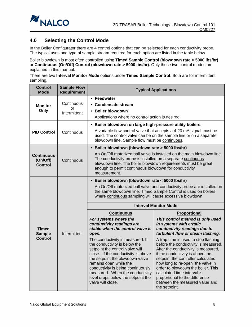
4.0 Selecting the Control ModeIn the Boiler Configurator there are 4 control options that can be selected for each conductivity probe. The typical uses and type of sample stream required for each option are listed in the table below.
Boiler blowdown is most often controlled using Timed Sample Control (blowdown rate < 5000 lbs/hr)or Continuous (On/Off) Control (blowdown rate > 5000 lbs/hr). Only these two control modes are explained in this manual.There are two Interval Monitor Mode options under Timed Sample Control. Both are for intermittent sampling.
Control Mode
Sample Flow Requirement Typical Applications
Monitor Only
Continuous or
Intermittent
• Feedwater• Condensate stream• Boiler blowdown
Applications where no control action is desired.
PID Control Continuous
• Boiler blowdown on large high-pressure utility boilers. A variable flow control valve that accepts a 4-20 mA signal must be used. The control valve can be on the sample line or on a separate blowdown line. Sample flow must be continuous.
Continuous(On/Off) Control
Continuous
• Boiler blowdown (blowdown rate > 5000 lbs/hr)An On/Off motorized ball valve is installed on the main blowdown line. The conductivity probe is installed on a separate continuousblowdown line. The boiler blowdown requirements must be great enough to permit continuous blowdown for conductivity measurement.
Timed Sample Control
Intermittent
• Boiler blowdown (blowdown rate < 5000 lbs/hr)An On/Off motorized ball valve and conductivity probe are installed on the same blowdown line. Timed Sample Control is used on boilers where continuous sampling will cause excessive blowdown.
Interval Monitor Mode
ContinuousFor systems where the conductivity readings are stable when the control valve is open. The conductivity is measured. If the conductivity is below the setpoint the control valve will close. If the conductivity is above the setpoint the blowdown valve remains open while the conductivity is being continuouslymeasured. When the conductivity level drops below the setpoint the valve will close.
ProportionalThis control method is only used in systems with erraticconductivity readings due to turbulent flow or steam flashing.A trap time is used to stop flashing before the conductivity is measured. After the conductivity is measured,if the conductivity is above the setpoint the controller calculates how long to re-open the valve in order to blowdown the boiler. This calculated time interval is proportional to the difference between the measured value and the setpoint.

3D TRASAR Boiler Technology – Blowdown Control 101OM0227________________________________________________________________________
Nalco Global Equipment Solutions 9
5.0 Blowdown System Plumbing
5.1 Continuous Blowdown (ON/OFF) Control – (Blowdown Rate > 5000 lbs/hr)
The diagram below is an example of a system set up for Continuous (On/Off) Control. A tee is installed on the main boiler blowdown line so a small amount of blowdown sample continuously flows through the conductivity probe assembly, past a flow control valve and then to drain. The main blowdown line extends to the motorized ball valve and flow control valve, which will be wired to and controlled by the 3D TRASAR controller.

3D TRASAR Boiler Technology - Blowdown Control 101 OM0227
Nalco Global Equipment Solutions 10
IMPORTANT NOTES:
1. The maximum temperature and pressure the conductivity probe can handle is 392ºF (200ºC) and 250 psig (17.2 bar). If the boiler operates above these conditions a sample conditioning system must be installed upstream of the conductivity probe to reduce the temperature and pressure.
CAUTION-DANGER: DO NOT install the conductivity in a boiler above 392ºF (200ºC) and 250 psig (17.2 bar). Probe failure and serious personal injury will result.
2. Both flow control valves downstream of the conductivity probe must be throttled back to maintain backpressure in the lines. The valves cannot be in the wide-open position. Otherwise, flashing in the line will occur if the line discharges to atmospheric pressure.
WARNING: Flashing will damage the conductivity probe and valve seals.
3. The motorized ball valve and flow control valve must be installed downstream from the conductivity probe. DO NOT install the conductivity probe between the valves. Flashing will occur.
4. The flow control valve must be installed downstream from the motorized ball valve to prevent flashing. Mount within 12-18” (0.3-0.5 m) of the motorized ball valve to avoid water hammer. DO NOT exceed 18” (0.5 m) or flashing may still occur inside the ball valve.
5. To ensure the piping remains full at the conductivity probe run a segment of piping downstream of the probe above the level of the probe cross (see diagram).
6. Restrictions in the piping upstream of the conductivity probe can cause a pressure drop and flashing. This will result in erratic readings and damage the probe and valve seals. All upstream isolation valves should be full-port and set to fully open.
7. Likewise, wide spots (small diameter piping bushed up to larger piping) upstream of the probe will cause flashing. Larger diameter piping from the boiler should transition down to the ¾” cross and probe without reverting to pipe segments of increased diameter. In addition, larger diameter piping should not be installed immediately downstream the ¾” cross.
8. Ensure the flush valve installed on the bottom of the cross and probe closes properly. Leaking will cause flashing at the probe or improper flooding of the conductivity probe.
9. The conductivity probe must be installed so the flow-through hole in the probe is in line with the sample flow. The K-factor is stamped on the probe and is aligned with the hole (see photo).
10. Mount the probe cross in a horizontal pipe run at least 2 ft (0.6 m) downstream of any elbows or fittings that may cause turbulence.
DO NOT mount the probe on a vertical pipe run.

3D TRASAR Boiler Technology – Blowdown Control 101OM0227________________________________________________________________________
Nalco Global Equipment Solutions 11
11. Piping can be reduced to ½” diameter downstream of the conductivity probes on boilers with blowdown rates under 5000 lbs/hr. So, a ½” motorized ball valve and flow control valve can be used.
12. Mount the motorized ball valve away from the boiler. So, it does not overheat the electronics.13. Follow pipe length guidelines shown on the diagrams. Piping that is too lengthy will require longer
flush times for the piping and probe to reach boiler water temperatures (required for accurate measurements). On smaller boiler systems this may result in excessive boiler blowdown.
5.2 Timed Sample Blowdown (ON/OFF) Control – (Blowdown Rate < 5000 lbs/hr)When using Timed Sample Blowdown (On/Off) Control the conductivity probe is mounted on the same line as the blowdown valve. The blowdown valve is periodically opened on a predetermined (timed) schedule. If the conductivity level is above the setpoint the valve remains open. How long the valve remains open depends on the Monitor Mode selected in the Configurator – Continuous or Proportional.
The piping, probe and valve arrangement is shown in the following diagram. Other keys aspects of the plumbing design are the same as listed for Continuous Blowdown (On/Off) Control.

3D TRASAR Boiler Technology - Blowdown Control 101 OM0227
Nalco Global Equipment Solutions 12
6.0 Conductivity Probe and Blowdown Relay Box Wiring
6.1 Compensating vs. Non-Compensating Conductivity ProbesThere are two types of conductivity contacting probe models supported.
Compensating - These probes are used for boiler blowdown monitoring where the sample temperature varies significantly or for condensate line monitoring. They have a built-in 4-wire RTD to measure the sample temperature. The controller corrects the conductivity measurement based on its temperature.
• A probe with a cell constant of 1.0 (conductivity = 100 - 10,000 µS/cm) is used for blowdown measurements.
• A probe with a cell constant of 0.1 (conductivity = 5 – 500 µS/cm) is used for condensate measurements
Note: A maximum of 3 RTD’s can be connected to the 3D TRASAR Controller (1 is required for the NCSM (RTD 2) and 1 is required for the Sample Conditioning System (RTD 1)).
Note: Nalco Best Practices is to use a compensating probe if there is only one boiler to control. The integral RTD can then be wired to the RTD 3 input.
Non-compensating - These are the standard probes used for blowdown and feed water monitoring where the sample temperature does not vary significantly. They do not include a built-in 4-wire RTD for temperature compensation.
• A probe with a cell constant of 1.0 (conductivity = 100 - 10,000 µS/cm) is used for blowdown and high-conductivity feedwater measurements.
• A probe with a cell constant of 0.1 (conductivity = 5 – 500 µS/cm) is used for high-purity feed water monitoring.
Note: The conductivity probe for feedwater monitoring (room temperature) has a PVC cover on the wires. The wiring and probe potting cannot withstand high temperature samples.
Note: When monitoring boiler feedwater the RTD on the sample conditioning system can be used for
temperature compensation.
Non-Compensating Blowdown Conductivity Probe
CompensatingBlowdown Conductivity Probe

3D TRASAR Boiler Technology – Blowdown Control 101OM0227________________________________________________________________________
Nalco Global Equipment Solutions 13
6.2 Conductivity Probe Wiring
Conductivity Probe Wires and Jumpers
• Correct wiring of the probes is very important.
� Use a minimum of 22 AWG, shielded wire (each pair is shielded).
� Probes wire lengths cannot exceed 1000 ft (305 m).
• Feedwater probe (mounted on same panel as controller) red and black wires are jumpered in the 3D TRASAR Controller.
• The red and black wires on ALL REMOTE MOUNTED PROBES (blowdown or condensate) must be jumpered at the J-box. Wires must be jumpered on the input side of the terminal strip inside the J-box).
• Jumpering the wires at the probe end enables 4 wires for the conductivity and 4 wires for the RTD (if using a probe with an integral RTD) to be sent back from the probe to the controller. Since the conductivity probe is normally installed a distance away from the controller, sending the conductivity/RTD signal through 4 wires will compensate for the length of the cable that is used.
• Signal loss will occur if the conductivity or RTD signal is sent through 2 wires (instead of four wires) over a distance.
Feedwater Conductivity Probe Wiring (non-compensating):
Since the feedwater conductivity probe is very close to the controller (mounted on same panel) only 2 wires are needed. Connections are made in the controller (TB13-15)
• Connect the probe red wire to the (-) terminal (this wire is physically attached to the body of the probe). Add a jumper wire from (-) to (S-).
• Connect the probe black wire to the (+) terminal (as this wire is physically attached to the center conductor of the probe). Add a jumper wire from (+) to (S+).
Note: The Sample Conditioning System RTD can be used for temperature compensation of feedwater conductivity measurements. This is normally wired to the RTD 1 input (TB-9) and is assigned in Configurator.
S++
S--
2
1S++
S--
Red wire
Black wire
Conductivity probe
Conductivity Inputs(TB13-TB15)
22 AWGshielded wire
Wires from probe (with jumpers)
Wires connected to controller
J-box
Input
Output

3D TRASAR Boiler Technology - Blowdown Control 101 OM0227
Nalco Global Equipment Solutions 14
Blowdown Conductivity Probe (non-compensating):
Since the blowdown conductivity probe is installed at a distance away from the controller, 4 wires are needed to compensate for the length of the cable that is used. Connections must be made in the J-box and in the controller.
Note: Some conductivity probes are supplied with jumpers already installed on the Black Wires and Red Wires.
• On the input side of the J-box terminal strip, connect the probe’s red wire to the first terminal. Add a jumper wire across the first and second terminals. On the output side of the terminal strip, connect a signal wire to each of the 2 terminals (opposite the probe’s red wire and jumper).
• On the input side of the J-box terminal strip, connect the probe’s black wire to the fourth terminal. Add a jumper wire across the third and fourth terminals. On the output side of the terminal strip, connect a signal wire to each of the 2 terminals (opposite the probe’s black wire and jumper).
• Connect the 2 wires from the probe’s red wire to TB13-15 (-) and (S-) terminals in the controller.
• Connect the 2 wires from the probe’s black wire to TB13-15 (+) and (S+) terminals in the controller.
Note: To minimize wiring errors between the J-box and controller, use color coded wires. Two separate twisted pair cables can be used (2 red wires and 2 black wires). See photo at the beginning of this section.
S++
S--
2
1S++
S--
BlackBlackRedRed
Red wire
Black wire
Conductivity probe (2-wire)
Conductivity Inputs(TB13-TB15)
J-Box
22 AWGshielded wire

3D TRASAR Boiler Technology – Blowdown Control 101OM0227________________________________________________________________________
Nalco Global Equipment Solutions 15
Blowdown/Condensate Conductivity Probe (compensating):
Since the blowdown/condensate conductivity probe is installed at a distance away from the controller 4 wires for conductivity and 4 wires for temperature are needed to compensate for the length of the cable that is used. This probe has an integral 4-wire RTD (2 white & 2 green wires). Connections must be made in the J-box and in the controller. However, since the RTD already has 4 wires, only the conductivity wires (red & black) must be jumpered in the J-box. Use separate cables for conductivity and temperature.
Note: Some conductivity probes are supplied with jumpers already installed on the Black Wires and Red Wires.
• On the input side of the J-box terminal strip, connect the probe’s red wire to the first terminal. Add a jumper wire across the first and second terminals. On the output side of the terminal strip, connect a signal wire to each of the 2 terminals (opposite the probe’s red wire and jumper).
• On the input side of the J-box terminal strip, connect the probe’s black wire to the fourth terminal. Add a jumper wire across the third and fourth terminals. On the output side of the terminal strip, connect a signal wire to each of the 2 terminals (opposite the probe’s black wire and jumper).
• On the input side of the J-box terminal strip, connect the probe’s 2 white wires to the fifth and sixth terminals. On the output side of the terminal strip, connect a signal wire to each of the 2 terminals(opposite the probe’s white wires).
S++
S--
2
1S++
S--
BlackBlackRedRed
Red wire
Black wire
Conductivity probe (6-wire)
Conductivity Inputs(TB13-TB15)
J-Box
S--
S++
3
S--
S++
2
S--
+1S+
White wires
Green wires
RTD Inputs(TB9)
WhiteWhiteGreenGreen
22 AWGshielded wire

3D TRASAR Boiler Technology - Blowdown Control 101 OM0227
Nalco Global Equipment Solutions 16
• On the input side of the J-box terminal strip, connect the probe’s 2 green wires to the seventh and eighth terminals. On the output side of the terminal strip, connect a signal wire to each of the 2 terminals (opposite the probe’s green wires).
• Connect the 2 wires from the probe’s red wire to TB13-15 (-) and (S-) terminals in the controller.
• Connect the 2 wires from the probe’s black wire to TB13-15 (+) and (S+) terminals in the controller.
• Connect the 2 wires from the probe’s white wires to TB9 (+) and (S+) terminals in the controller.
• Connect the 2 wires from the probe’s green wires to TB9 (-) and (S-) terminals in the controller.
3D TRASAR Conductivity Inputs (TB13-TB15)
All conductivity probes are connected in the 3D TRASAR Controller on terminal strip TB13-15.
• Feedwater probes (located on the same panel as the controller) are wired directly to the terminal strip.
• Remote probes (blowdown or condensate) probes are first wiredto a J-box. Wires (non-compensating 4-wires, compensating 8-wires) are then run from the J-box to the controller
Note: The conductivity probe RTD wires (white and green) are connected in the controller on terminal strip TB9
Note: When connecting the conductivity probe wires into the controller, it is important to note which input the conductivity probe is being wired into. This is critical when conductivity is being configured in the Configurator, especially, when multiple probes are being used.
Feedwaterconductivity probe
with jumpers
Remoteconductivity probe(jumpers in J-box)

3D TRASAR Boiler Technology – Blowdown Control 101OM0227________________________________________________________________________
Nalco Global Equipment Solutions 17
ConnectionDescription
Controller BoxBoard Reference
Controller BoxTerminal
Description
Conductivity Probe 6 TB15-6 6+ Pos. Cond. 6 (Red C+)
TB15-6 S6+ Positive Sense 6
TB15-6 S6- Negative Sense 6
TB15-6 6- Neg. Cond. 6 (Black C-)
Conductivity Probe 5 TB15-5 5+ Pos. Cond. 5 (Red C+)
TB15-5 S5+ Positive Sense 5
TB15-5 S5- Negative Sense 5
TB15-5 5- Neg. Cond. 5 (Black C-)
Conductivity Probe 4 TB14-4 4+ Pos. Cond. 4 (Red C+)
TB14-4 S4+ Positive Sense 4
TB14-4 S4- Negative Sense 4
TB14-4 4- Neg. Cond. 4 (Black C-)
Conductivity Probe 3 TB14-3 3+ Pos. Cond. 3 (Red C+)
TB14-3 S3+ Positive Sense 3
TB14-3 S3- Negative Sense 3
TB14-3 3- Neg. Cond. 3 (Black C-)
Conductivity Probe 2 TB13-2 2+ Pos. Cond. 2 (Red C+)
TB13-2 S2+ Positive Sense 2
TB13-2 S2- Negative Sense 2
TB13-2 2- Neg. Cond. 2 (Black C-)
Conductivity Probe 1 TB13-1 1+ Pos. Cond. 1 (Red C+)
TB13-1 S1+ Positive Sense 1
TB13-1 S1- Negative Sense 1
TB13-1 1- Neg. Cond. 1 (Black C-)

3D TRASAR Boiler Technology - Blowdown Control 101 OM0227
Nalco Global Equipment Solutions 18
3D TRASAR Controller Temperature Inputs (1000 ohm, platinum RTD)
Desc.Controller
Board Terminal DescriptionRTD Wires Labels & (Color)
NCSM SCS Conductivity
RTD Probe 3 TB9–3 3- Neg. RTD 3 TC- com
(Green) (Black or White) TC (Green)
TB9-3 S3- Neg. Sense 3 TC-(White) (Black or White) TC
(Green)
TB9-3 S3+ Pos. Sense 3 TC+(Red) (Red) TC
(White)
TB9-3 3+ Pos. RTD 3 TC+ com(Black) (Red) TC
(White)
RTD Probe 2 TB9-2 2- Neg. RTD 2 TC- com
(Green) (Black or White) TC (Green)
TB9-2 S2- Neg. Sense 2 TC-(White) (Black or White) TC
(Green)
TB9-2 S2+ Pos. Sense 2 TC+(Red) (Red) TC
(White)
TB9-2 2+ Pos. RTD 2 TC+ com(Black) (Red) TC
(White)
RTD Probe 1 TB9-1 1- Neg. RTD 1 TC- com
(Green) (Black or White) TC (Green)
TB9-1 S1- Neg. Sense 1 TC-(White) (Black or White) TC
(Green)
TB9-1 S1+ Pos. Sense 1 TC+(Red) (Red) TC
(White)
TB9-1 1+ Pos. RTD 1 TC+ com(Black) (Red) TC
(White)
Note: If the RTD has only 2 wires, connect one RTD wire to (+) and jumper (+) to (S+). Connect the other RTD wire to (-) and jumper (-) to (S-).
Note: RTD wire colors vary by device. See above table for devices used on standard 3D TRASAR Systems.

3D TRASAR Boiler Technology – Blowdown Control 101OM0227________________________________________________________________________
Nalco Global Equipment Solutions 19
6.3 Blowdown Relay Box Connections
The Blowdown Relay Box provides 4 single-pole, double-throw relays that can be used to power open and power close motorized ball valves. It will be pre-wired to relays 1-4 in the 3D TRASAR Boiler controller. All connections to the valves are made in the Blowdown Valve Relay Box.
Note: Although the blowdown valve is grounded via the piping local regulations may require a ground wire to be run from the valve to the relay box. There is a grounding strip in the box.
Note: The Blowdown Relay Box must be connected to a 120 VAC, 10A power source (Somemodels sold outside the US require 220 VAC, 5A power).
OMRONG2R-1-S-AC120R
SPDT RelayR4
Common (4)
NC (2)
NO (3)
115RelayCoil
Coil + (5)
Coil - (1)
OMRONG2R-1-S-AC120R
SPDT RelayR2
Common (4)
NC (2)
NO (3)
115RelayCoil
Coil + (5)
Coil - (1)
OMRONG2R-1-S-AC120R
SPDT RelayR3
Common (4)
NC (2)
NO (3)
115RelayCoil
Coil + (5)
Coil - (1)
OMRONG2R-1-S-AC120R
SPDT RelayR1
Common (4)
NC (2)
NO (3)
115RelayCoil
Coil + (5)
Coil - (1)
To motorized ball valve N/C 4
To motorized ball valve N/O 4
To motorized ball neutral 1
Blowdown Relay Box (4 Relays)
NO
N
3D TRASARController
RelayConnections
3
2
4
5
1
NO
N
3
2
4
5
1
NO
N
3
2
4
5
1
NO
N
3
2
4
5
1
120 VAC Hot
Fuse
10A,
Slo
Blo
120 VAC Neutral
Earth Ground
Attached to Back Plate
To motorized ball neutral 2
To motorized ball neutral 3
To motorized ball neutral 4
To motorized ball valve N/C 3
To motorized ball valve N/O 3
To motorized ball valve N/C 2
To motorized ball valve N/O 2
To motorized ball valve N/C 1
To motorized ball valve N/O 1
Motor ActuatorConnections
120 VACPower SupplyConnections

3D TRASAR Boiler Technology - Blowdown Control 101 OM0227
Nalco Global Equipment Solutions 20
Connect ToBall Valve N/O
(Top Row)
Connect ToBall Valve N/C(Middle Row)
Connect ToBall Valve
Neutral
Connect To120 VAC/10APower Supply

3D TRASAR Boiler Technology – Blowdown Control 101OM0227________________________________________________________________________
Nalco Global Equipment Solutions 21
6.4 3D TRASAR Boiler Controller Terminal Connections Diagram
AC
Inpu
t Pow
er90
-240
VA
C, 5
0/60
Hz
15A
@ 1
20V
, 15A
Ser
vice
7.5A
@ 2
40 V
AC
mA
/VSE
LEC
TOR
4-20
mA
0-10
V
1 2
3 4 RTD INPUTS
4-20 mA OUTPUTS
ANALOG INPUTS
TB9TB10
TB22
4 3 2 1
TB8
DIGITAL INPUTS
3D T
RA
SAR
BO
ILER
CO
NTR
OLL
ERTE
RM
INA
L C
ON
NEC
TIO
NS
81-0
027-
0001
2Fu
se R
atin
gs5x
20 m
m S
low
Blo
wM
ain
Pow
er (2
) = 1
.0A
SB
Ala
rm R
elay
= 1
.0A
SB
Con
trol R
elay
s =
2.5A
SB
Key
L :
Line
AC
(Hot
)N
: N
eutra
l AC
: E
arth
Gro
und
NO
: N
orm
ally
Ope
nN
C :
Nor
mal
ly C
lose
dC
:
Rel
ay C
omm
on
Line
2 (N
)Fu
seLi
ne 1
(L)
Fuse
90-2
40 V
AC
50/6
0 H
zTB
1C
ontr
ol R
LY 1
TB2
Con
trol
RLY
2TB
3C
ontr
ol R
LY 3
TB4
Con
trol
RLY
4TB
5C
ontr
ol R
LY 5
TB6
ALA
RM
TB7
MO
DEM
CA
RD
CONDUCTIVITY INPUTS
TB15 TB14 TB13
GN
D
TB21 TB20 TB19 TB18 TB17 TB16
MODBUS MASTER SCADA 485SCADA
232INTERLOCK
GN
D
pH/O
RP
pH/O
RP
TB11
TB12
REL
AY
CO
NN
ECTI
ON
S
NC
1 2 3
L N
NO
NC
LN
ON
CL
NO
NC
LN
ON
CL
NO
NC
LN
OC
+- 1
+-
2
S++ S- -2 1
S++ S- -S++ S- -4 3
S++ S- -S++ S- -6 5
S++ S- -
+-GN
DR
XTX1B 1A2B 2A
- +- +- +- +- +8
- - - - - - -+ + + + + + +
7 6 5 4 3 2 1
+- 24V
4
+- 24V
+- 24V
+- 24V
3 2 1
S-- S+ +3
S-- S+ +2
S-- +1
S+
6V 1B 1AGN
D
6V 2B 2AGN
D
Not
e:Fa
ctor
y-in
stal
led
jum
per b
etw
een
“C” a
nd “L
” to
prov
ide
120
VA
C p
ower
is n
ot s
how
n.
3D TRASAR Boiler Technology - Blowdown Control 101 OM0227
Nalco Global Equipment Solutions 22
7.0 Conductivity Monitor and Control Setup
The Configurator is used to set up conductivity monitoring and control. The settings are described in the Configurator Help Screens (F1). Alarms are described in Appendix C.
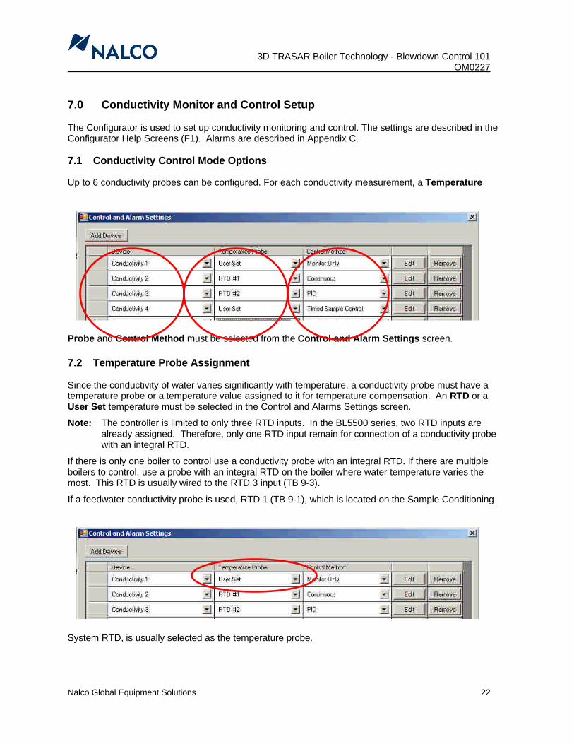
7.1 Conductivity Control Mode Options
Up to 6 conductivity probes can be configured. For each conductivity measurement, a Temperature
Probe and Control Method must be selected from the Control and Alarm Settings screen.
7.2 Temperature Probe Assignment
Since the conductivity of water varies significantly with temperature, a conductivity probe must have a temperature probe or a temperature value assigned to it for temperature compensation. An RTD or a User Set temperature must be selected in the Control and Alarms Settings screen.
Note: The controller is limited to only three RTD inputs. In the BL5500 series, two RTD inputs are already assigned. Therefore, only one RTD input remain for connection of a conductivity probe with an integral RTD.
If there is only one boiler to control use a conductivity probe with an integral RTD. If there are multiple boilers to control, use a probe with an integral RTD on the boiler where water temperature varies the most. This RTD is usually wired to the RTD 3 input (TB 9-3).
If a feedwater conductivity probe is used, RTD 1 (TB 9-1), which is located on the Sample Conditioning
System RTD, is usually selected as the temperature probe.

3D TRASAR Boiler Technology – Blowdown Control 101OM0227________________________________________________________________________
Nalco Global Equipment Solutions 23
If a blowdown probe without an RTD is being used, Select User Set for the Temperature Probe. The sample water temperature at the probe must be manually entered in the Conductivity Control screen. In the example above, select Edit for Conductivity 2 to get to this screen.
The temperature of the boiler water can be determined from the operating pressure of the boiler. Refer to Appendix B for the Boiler Saturated Steam Table. The boiler water temperature remains constant as long as pressure remains constant.
Note: The sample temperature will drop between the boiler and conductivity probe. It is best to measure the actual sample temperature at the probe for accurate readings.
Note: Entering the correct temperature is very important. The conductivity measurement will beoff by approximately 11% for every 10°F (5.5°C)
7.3 Conductivity Control Mode
There are 4 control options that can be selected for conductivity probe measurement. These can be
selected from the Control Method drop down list. The typical uses and type of sample stream required for each option are listed in Section 3.0.
Note: Verify that the boiler conductivity setpoint can be achieved via manual control before switching the system to auto control, especially on new installations.

3D TRASAR Boiler Technology - Blowdown Control 101 OM0227
Nalco Global Equipment Solutions 24
7.3.1 Monitor Only MethodIt is recommended to select this method initially for new installations. Monitoring the boiler blowdown conductivity for a short period of time before going into control, allows the user to get a better feel for what control method to use and what parameters are needed to achieve good boiler cycle control.
The Conductivity Name, Operating Temperature (if User Set is selected, enter the boiler water temperature) and Alarm Settings are entered in the Conductivity Control – Monitor Only screen. If a probe with an integral RTD is used, the Operating Temp field will be disabled.
7.3.2 PID Control Method
PID Control is used for large high pressure utility boilers were boiler blowdown is on a continuous basis. A variable flow control valve is used to accept a 4-20 mA signal from the 3D TRASAR controller. PID control of the blowdown conductivity is based on PID parameters that are manually entered by the user. Only manual PID tuning is available for this control method. For conductivity, the recommendation is to use Proportional control (Integral and Derivative terms are set to 0).
To use Proportional Control with Conductivity, first select PID as the control method for the Conductivity device. The Conductivity Name, Output, Output Name, Operating Temperature (if User Set was selected, enter the boiler water temperature), Control Settings and Alarm Settings must be entered in the Conductivity Control – PID screen. The PID parameters are entered in the Advanced PID Settings screen. If a probe with an integral RTD is used, the Operating Temp field will be disabled.

3D TRASAR Boiler Technology – Blowdown Control 101OM0227________________________________________________________________________
Nalco Global Equipment Solutions 25
PID Control Notes:
• Proportional conductivity blowdown control is Direct Acting.
• Set the Integral and Derivative terms to 0.
• If the conductivity probe is installed on the same blowdown line as the control valve, the Output Minmust be set to a value large enough to ensure a constant sample flow across the conductivity probe.
• The Output Max is used to prevent the control valve from opening so wide that the boiler blows down too rapidly, upsetting boiler operation.
• The Max Change % is used to slow down the response of the control valve to simulate the response of a pneumatic valve (default = 10%). If the Update Interval is left at the default 5 seconds it will take 50 seconds to fully close the valve from fully open.
• The Scale High and Scale Low must be set above/below any alert or alarm values.
• The Proportional value is calculated using the following equation:
Proportional = [Acting x (Setpoint – Cond.Max.) x 100] x 100
[(Output Max – Output Min) x (Scale High – Scale Low)]
Example:Setpoint = 3000 µS/cmCondMax = 6000 µS/cmOutput Min = 5%Output Max = 40%Acting = -1 (Direct Acting PID equation for Conductivity Blowdown Control)Scale Low = 1500 Scale High = 5500
Calculation: P = [ -1 x ( 3000 - 6000 ) x 100] x 100 = 214.29[( 40 – 5 ) x ( 5500 – 1500 )]
See the Configurator Help Screens (F1) for detailed instructions.

3D TRASAR Boiler Technology - Blowdown Control 101 OM0227
Nalco Global Equipment Solutions 26
7.3.3 Continuous (ON/OFF) Control Method
Continuous method enables traditional ON/OFF control. It is often used to control boiler conductivity levels in systems where a small amount of boiler water is continuously bled off from a secondary blowdown line. This stream is continuously monitored, providing a real-time conductivity reading. When the measured conductivity increases above the setpoint, the control valve, which is installed on the main blowdown line, is opened to increase the blowdown rate and reduce the measured conductivity to below the setpoint. This method, which is the easiest method to employ, is used for systems were the blowdown rate is greater than 5000 lbs/hr.
In Section 4.1 there is a schematic of a system set up in a Continuous (On/Off) control mode. A tee is installed on the main blowdown line so a small amount of blowdown sample continuously flows through the conductivity probe assembly, past a flow control valve and then to drain. The main blowdown extends to the motorized ball valve, which will be wired to and controlled by the 3D TRASAR controller.
IMPORTANT NOTE: Both flow control valves must be throttled back to maintain backpressure in the lines. The valves cannot be in the wide-open position. Otherwise, flashing in the line will occur if the line discharges to atmospheric pressure.
In the Configurator, the Conductivity Name, Output, Output Name, Operating Temperature (if User Set was selected, the boiler water temperature is entered), Control Settings and Alarm Settings must be entered in the Conductivity Control – Continuous screen. If a conductivity probewith an integral RTD is used, the Operating Temp field will be disabled. The +band must also be entered. The control valve will open when the conductivity level rises to the Set Point +band and close when the conductivity level falls to the Set Point .

3D TRASAR Boiler Technology – Blowdown Control 101OM0227________________________________________________________________________
Nalco Global Equipment Solutions 27
7.3.4 Timed Sample (ON/OFF) Control MethodTimed Sample control method is used on boilers were continuous sampling will cause excessive blowdown. This method is used for systems were the blowdown rate is less than 5000 lbs/hr. In Section 4.2 there is a schematic of a system that is set up in a Time Sample (On/Off) Control mode.
Timed Sample enables ON/OFF control of boiler blowdown conductivity. The conductivity probe is mounted on the same line as the control valve. The control valve is periodically opened on a predetermined (timed) schedule. If the conductivity level is above the setpoint, the valve remains open. How long the valve remains open depends on the Monitor Mode selected.
There are two Interval Monitor Modes available for Timed Sample Control – Continuous and Proportional. The table below explains the differences between the two modes.
Interval Monitor Mode
Typical Applications
Continuous
For systems where the conductivity readings are stable when the control valve is open. After the conductivity is measured, the controller compares the measurement to the setpoint. If the conductivity is below the setpoint, the control valve will close. If the conductivity is above the setpoint, the control valve remains open while the conductivity is being continuously measured. When the measured conductivity drops below the setpoint, the control valve will close.
Proportional
This control method is only used in systems with erratic conductivity readings due to turbulent flow or steam flashing.In these systems, a trap time is used to prevent the blowdown sample from flashing while the conductivity is measured. After the conductivity is measured, the controller compares the measurement to the setpoint. If the conductivity is above the setpoint, the controller calculates how long to re-open the control valve in order to blowdown the boiler. This calculated time interval is proportional to the difference between the measured value and the setpoint. See Section 7.7.3 on how to set up Timed Sample - Proportional control.
Note: When using Timed Sample Control (either Continuous or Proportional monitor mode) a Sample Schedule must be defined.

3D TRASAR Boiler Technology - Blowdown Control 101 OM0227
Nalco Global Equipment Solutions 28
Timed Sample – Continuous Mode
In the Configurator, the Conductivity Name, Output, Output Name, Operating Temperature (if User Set was selected, enter the boiler water temperature), Control Settings, and Alarm Settingsmust be entered in the Conductivity Control – Timed Sample screen. If a conductivity probe with an integral RTD is used, the Operating Temp field will be disabled. The +band is also disabled in this mode.
The Interval Details and Sample Schedule need to be configured (see Sections 7.4 and 7.5 for more details). The defaults that have been built into these screens are realistic starting values for most systems. The user can choose to use these default values initially, or change them. Some of the parameters have Minimum and Maximum limits to prevent the user from entering unrealistic values.

3D TRASAR Boiler Technology – Blowdown Control 101OM0227________________________________________________________________________
Nalco Global Equipment Solutions 29
Timed Sample – Proportional Mode
In the Configurator, the Conductivity Name, Output, Output Name, Operating Temperature (if User Set was selected, the boiler water temperature is entered), Control Settings, and Alarm Settings must be entered in the Conductivity Control – Timed Sample screen. If a conductivity probe with an integral RTD is used, the Operating Temp field will be disabled.
Note: The Band field is now active and MUST be calculated. See Section 7.6 for details.
As with the Continuous mode, the Interval Details and Sample Schedule need to be configured (see Sections 7.4 and 7.5 for more details). The defaults that have been built into these screens are realistic starting values for most systems. The user can choose to use these default values, initially, or change them. Some of the parameters have Minimum and Maximum limits to prevent the user from entering unrealistic values.
3D TRASAR Boiler Technology - Blowdown Control 101 OM0227
Nalco Global Equipment Solutions 30
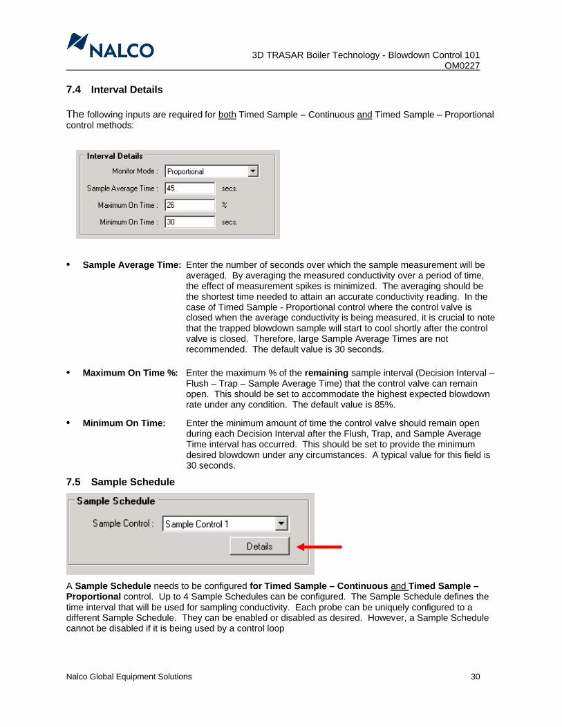
7.4 Interval Details
The following inputs are required for both Timed Sample – Continuous and Timed Sample – Proportional control methods:
• Sample Average Time: Enter the number of seconds over which the sample measurement will be averaged. By averaging the measured conductivity over a period of time, the effect of measurement spikes is minimized. The averaging should be the shortest time needed to attain an accurate conductivity reading. In the case of Timed Sample - Proportional control where the control valve is closed when the average conductivity is being measured, it is crucial to note that the trapped blowdown sample will start to cool shortly after the control valve is closed. Therefore, large Sample Average Times are not recommended. The default value is 30 seconds.
• Maximum On Time %: Enter the maximum % of the remaining sample interval (Decision Interval –Flush – Trap – Sample Average Time) that the control valve can remainopen. This should be set to accommodate the highest expected blowdown rate under any condition. The default value is 85%.
• Minimum On Time: Enter the minimum amount of time the control valve should remain open during each Decision Interval after the Flush, Trap, and Sample Average Time interval has occurred. This should be set to provide the minimum desired blowdown under any circumstances. A typical value for this field is 30 seconds.
7.5 Sample Schedule
A Sample Schedule needs to be configured for Timed Sample – Continuous and Timed Sample –Proportional control. Up to 4 Sample Schedules can be configured. The Sample Schedule defines the time interval that will be used for sampling conductivity. Each probe can be uniquely configured to a different Sample Schedule. They can be enabled or disabled as desired. However, a Sample Schedule cannot be disabled if it is being used by a control loop

3D TRASAR Boiler Technology – Blowdown Control 101OM0227________________________________________________________________________
Nalco Global Equipment Solutions 31
Output:
A unique relay must be selected for each Sample Schedule. In the case of blowdown control, the Sample Schedule Output is usually set to the same relay chosen on the Conductivity Control - Timed Sample screen. The control valve that is wired to the chosen relay output is used for both sampling and control.
Sample Rate:
Select the sampling rate based on when high load periods are expected for the boiler. The Sample Rate needs to be chosen to match the times when the boiler is operating at peak output. Some manufacturing facilities only operate Monday through Friday and leave the boiler in a low load or standby state over the weekend.
A Daily High MTWTF sample rate would best fit this plant that operates under peak conditions during the week and goes on standby mode on the weekends.
If Normal 24/7 is chosen for a facility, the sampling interval will remain the same over any time period. The options are:
§ Normal 24/7§ Daily High 7 Days§ Daily High MTWTF
Note: If “Normal 24/7” is selected then “High Rate Start”, “High Rate End” and “High Decision Int” fields are disabled because they do not apply to a “normal” load situation

3D TRASAR Boiler Technology - Blowdown Control 101 OM0227
Nalco Global Equipment Solutions 32
High Rate Start:
Starting time for a high load sampling period.
High Rate End:
Ending time for a high load sampling period.
High Decision Int:
Length of time for the complete Sample Schedule (cycle) in minutes for high load periods.
Normal Decision Int:
Length of time desired between sampling in minutes for normal load periods. If the boiler operates in a Normal 24/7 mode, this is the only decision interval that is entered. If this value is set too low, sampling of the boiler blowdown will be too frequent, which may cause the boiler water conductivity to decrease over time. Under this condition, the sampling is enough to inadvertently blowdown the boiler. If this value is too large, sampling will be too infrequent, causing the boiler water conductivity to increase over time. This will result in over cycling. The default value is 60 minutes.
Note: During the initial setup, it is better to choose a low decision interval. This may waste a small amount of energy until a final value is determined, but will greatly reduce the chance of over-cycling and damage to the system.
Enable Trap Time:
A sample trap is used to stabilize samples when turbulent flow or entrained steam prevents accurate conductivity measurements. The sample Trap Time is in seconds. An important consideration is that too long of a trap time will result in a decrease in the sample temperature. The default value is 10 seconds. This field is only enabled when Timed Sample – Proportional control is chosen.
Flush Time:
The minimum time needed (seconds) to flush the sample line and ensure the sample will reach its maximum temperature. A value between 0 and 86,400 seconds can be entered.
If flush time is too short the sample will not be at its maximum temperature and the conductivity value will continue to rise as the sample is measured. If this time interval is too large, the boiler could blow down too much as a result of the sampling alone. The default value is 180 seconds.
Note: Certain rules have been established covering the allowable entries for the time intervals. An error message will appear if one or more of the entered values are invalid.
Example: Decision Int > Flush Time + Trap Time + Average Time + Max Valve On Time

3D TRASAR Boiler Technology – Blowdown Control 101OM0227________________________________________________________________________
Nalco Global Equipment Solutions 33
7.6 Setting Up Timed Sample – Proportional Control
The control values entered in the Configurator should closely mimic how the system is currently operated. Otherwise, the boiler will likely blowdown too much or not enough. Below is a diagram of the conductivitymeasurement-control cycle.
At the beginning of the Decision Interval the valve opens (Decision Point) to flush the blowdown line, providing a fresh sample to the conductivity probe (Flush Time). Next, the control valve is closed to trap the sample and establish an accurate conductivity reading (Trap Time). The conductivity is measured and averaged (Sample Average Time). Finally, a decision is made as to how long the valve should be re-opened (Calculated Valve On Time). See the table below for more details on the controller response.
To determine the correct values it is important to understand how the (Blowdown) Valve On Time is calculated. The Maximum Calculated (Blowdown) Valve On Time acts as a first defense against blowing down a boiler too much. This value establishes a time limit on how long the control valve can remain open after the conductivity has been measured. It is calculated as follows:
Max. Calc. Valve On Time = (Decision Interval – Flush –Trap – Average) x Maximum On Time %
Example: Decision Interval = 60 minutesFlush Time = 240 seconds = 4 minutesTrap Time = 30 seconds = 0.5 minutesSample Average Time = 30 seconds = 0.5 minute)Maximum On Time % = 20%
Max. Calc. Valve On Time = (60 – 4 – 0.5 –0.5) x 0.20 = 11 Minutes
The Calculated Valve On Time is a portion of the Maximum Calculated Valve On Time. The higher the conductivity measurement is above the Setpoint, the longer the blowdown valve will be open. It is calculated as follows.
Calc. Valve On Time = (Max. Calc. Valve On Time) x (Conductivity Value Above Setpoint)+band
Example:

3D TRASAR Boiler Technology - Blowdown Control 101 OM0227
Nalco Global Equipment Solutions 34
Decision Interval = 60 minutesFlush Time = 240 seconds = 4 minutesTrap Time = 30 seconds = 0.5 minutesSample Average Time = 30 seconds = 0.5 minutesMaximum On Time % = 20%Conductivity Setpoint = 5000 µS/cmAveraged Conductivity = 5050 µS/cm+band = 100 µS/cm
Calc. Valve On Time = (60 – 4 – 0.5 –0.5) x 0.20 x (5050-5000) = 5.5 minutes 100
Note: The +band value calculation is presented later in this section of the manual.
How is Valve Open Time Determined?
Measured Conductivity Controller Output Response (Valve Action)
Avg. Cond. < Setpoint Minimum On Time
Avg. Cond. > Setpointand
(Avg. Cond – Setpoint). < BandCalculated Valve On Time
Avg. Cond. > Setpointand
(Avg. Cond – Setpoint). > BandMaximum Calculated Valve On Time
Note: Minimum On Time (seconds) and Maximum On Time (%) are entered by the user on the Timed Sample – Continuous or Timed Sample – Proportional screen, under Interval Details section.
Max. Calc. Blowdown Valve On Time

3D TRASAR Boiler Technology – Blowdown Control 101OM0227________________________________________________________________________
Nalco Global Equipment Solutions 35
Determining Values To Enter Into The Configurator.
The first step to determine the appropriate values for your system is to perform a Blowdown Test. This test is used to measure the time it takes to blow down the boiler from a conductivity value above setpoint.
1. Determine the time-based intervals (Decision Int, Flush Time, Trap Time, and Sample Average Time). The Boiler operators will be an excellent resource. They know their systems very well and can aide in the determining an acceptable time interval and the required blowdown time.
Note: The default values can be used initially. Over time, as the user becomes more comfortable with the control, these values can be changed accordingly.
2. Perform a Blowdown Test. This test is performed to determine the actual time it takes for the boiler water to drop from a starting conductivity value to some ending conductivity value.
3. Perform calculations to determine Maximum On Time % and +band values.
Example:It is determined that the following values are acceptable.
Decision Interval = 120 minutesFlush Time = 180 seconds = 3 minutesTrap Time = 15 seconds = 0.25 minutesSample Average Time = 45 seconds = 0.75 minutesConductivity Setpoint = 3500 µS/cm
Additional information was provided by the boiler operators.• Boiler is generally blown down the when the conductivity is approx. 100 µS/cm above setpoint.
(“Conductivity Value Above Setpoint”)• The boiler is never blown down more than 30 minutes at a given time. (“Max. Calc. Valve On
Time”). This prevents shocking the boiler with cold feed water and allows the deaerator to maintain its level.
The Blowdown Test gave the following result. • At a conductivity value of 3600 µS/cm, it took 12 minutes to blow down the boiler until the
conductivity read 3500 µS/cm. Calc. Valve On Time = 12 minutes
Blowdown Test = (3600 – 3500) µS/cm = 8.33 µS/cm 12 min min
1. First, calculate the Maximum On Time %.Max. Calc. Valve On Time = (Decision Interval – Flush –Trap – Average) x Maximum On Time %
30 = (120 – 3 – 0.25 – 0.75) x Maximum On Time %
Maximum On Time % = 0.259 or 25.9% (Round 25.9% to 26%)
2. Next, calculate the +band parameter. Band = (Max. Calc. Valve On Time) x (Blowdown Test)
Band = (120 – 3 – 0.25 – 0.75) x 0.26 x (3600-3500) 12
Band = (116 x 0.26 x 8.33) = 251.3 µS/cm

3D TRASAR Boiler Technology - Blowdown Control 101 OM0227
Nalco Global Equipment Solutions 36
Therefore, the values entered into the Configurator would be as follows:
Decision Interval = 120 minutesFlush Time = 180 seconds = 3 minutesTrap Time = 15 seconds = 0.25 minutesSample Average Time = 45 seconds = 0.75 minutesConductivity Setpoint = 3500 µS/cmMaximum On Time % = 26%Band = 251 µS/cm
Note: Monitor the system very closely for the first few weeks and make adjustments to ensure boiler blowdown control is operating successfully. The values input by the user are not going to be perfect. Every blowdown cycle is slightly unique and the calculated blowdown time is not going to be the exact amount of time needed for every cycle. The values must be adjusted after multiple decision intervals have occurred (unless there is an extreme response occurring). The results should be trended to determine what adjustments are needed.
Note: Review all the configured devices and control outputs on the Control and Output Summary screen to be sure no input errors have been made. Print the screen for reference. Save and Close (for future Uploading) or Upload the settings to the controller.
7.7 Troubleshooting and Adjustment Tips for Interval Control
1. The boiler conductivity continues to decrease over multiple decision intervals (too much blowdown). Solution 1: Decision interval needs to be increased.
Note: Changing the decision interval causes a change in the maximum blowdown time and the Maximum On Time % will need to be adjusted accordingly.
Solution 2: Slightly close the Flow Control Valve (decrease “turns open”).
2. Boiler conductivity continues to increase over multiple decision intervals in Timed Sample -Proportional Mode (too little blowdown).Solution 1: Increase the Maximum On Time %. If the Maximum On Time % is already large
(>85%), shortening the decision interval or making changes to the Band parameter may need to be considered.
Note: Changing the decision interval causes a change in the maximum blowdown time and the Maximum On Time % may need to be adjusted.
Solution 2: Slightly open the Flow Control Valve (increase “turns open”). Note: Be careful not to open the valve too much as to cause flashing.
3. Boiler conductivity is only a few percent above setpoint, but the control valve remains open longenough to reduce the conductivity where it takes multiple decision intervals to reach setpoint again.
Solution: Reduce the Maximum On Time %.

3D TRASAR Boiler Technology – Blowdown Control 101OM0227________________________________________________________________________
Nalco Global Equipment Solutions 37
8.0 Conductivity Calibration
To perform the conductivity calibration, select the Actions key on the 3D TRASAR controller and Select Calibrate.
Highlight the conductivity probe you wish to calibrate and hit Select.
1-Point Calibration utilizes the boiler water as the calibration point. It is recommended to perform this step after a 2-point calibration has been performed to fine-tune the calibration. The probe is left in the blowdown line while a representative (cooled) sample is measured from a reliable handheld meter.
2-Point Calibration utilizes conductivity standards that cover the range of measurement. A 2-point calibration is required for all new installations. When a major error in the conductivity measurement has developed due to excessive fouling or loading on the probe, a 2-point calibration is also recommended.
8.1 Recommended Conductivity Calibration Standards
The table below lists the conductivity calibration solutions that are available through our Equipment Catalog.
Calibration Standards Part Number0 µS/cm (dry in Air) --
40 µS/cm 460-S0299.75200 µS/cm 460-S0743.75600 µS/cm 460-S0298.753000 µS/cm 460-S0297.755000 µS/cm 001-H07642.88
10,000 µS/cm 001-H07641.88
The recommendation for conductivity calibration is to choose two standards that encompass the expected conductivity range of measurement for the system. The tables below list the combinations of standards that are required for boiler feedwater and blowdown applications.
Feedwater & Condensate: Blowdown:K = 1.0 K = 0.1 K = 1.0
CalibrationSolution #1
CalibrationSolution #2
Calibration Solution #1
Calibration Solution #2
Calibration Solution #1
Calibration Solution #2
0 40 0 40 600 300040 600 40 200 600 50000 600 3000 5000
3000 10,0005000 10,000
IMPORTANT NOTE: If combinations other than what is listed are used, (i.e., 40 µS/cm and 10,000 µS/cm) the calibration will fail.
This is due to the fact that the resulting conductivity counts for the incorrect combination of standards will fall outside of the 3D TRASAR controller’s calibration range.

3D TRASAR Boiler Technology - Blowdown Control 101 OM0227
Nalco Global Equipment Solutions 38
8.2 1-Point Calibration
Note: A 1-point conductivity calibration must be performed after a 2-point calibration as part of every field start–up. This is important because the 2-point calibration is performed under static conditions. The 1-point calibration will compensate for the flowing sample and the dynamics of the system.
STEP 1 Leave the conductivity probe in the cross assembly. For systems using Continuous (On/Off) control, allow several minutes for the probe to equilibrate to the conditions of the boiler water that is continuously flowing through the cross assembly.
For systems using Timed Sample (Continuous or Proportional) control, the blowdown control valve will need to be manually opened to allow sample to flow past the conductivity probe. To do this, set the corresponding Relay Output for the motorized valve to “Manual On” (Actions => Manual Control => (corresponding) Relay => Manual On). This will allow water to flow through the conductivity probe.
Allow enough time for the probe to equilibrate to the boiler water conditions:• Timed Sample – Proportional: Time = (Flush + Trap + Average) times• Timed Sample – Continuous: Time = (Flush) time. • Feedwater Module: Time = Allow at least 20 minutes for the probe to
equilibrate to system conditions.
On the 3D TRASAR controller, highlight 1-point (Process) calibration then hit Select.
STEP 2 Using a handheld, temperature-compensating conductivity meter of known accuracy and calibration, locally sample the boiler water and measure the (non-neutralized) conductivity value. For boiler blowdown, sample cooling is required.
STEP 3 Continuous (On/Off) or Timed Sample – Continuous:After the probe has equilibrated to the blowdown sample, compare the Current conductivity reading on the display screen to the reading obtained from the handheld meter in Step 2. These values should be relatively close (i.e., this should not be a 50% offset). Proceed to Step 4.
Timed Sample – Proportional:The control valve will need to be closed to trap the blowdown sample, in order to prevent the sample from flashing. A stable Current conductivity reading can then be obtained. To do this, set the corresponding Relay Output for the motorized valve from “Manual On” to “Manual Off” (Actions => Manual Control => (corresponding) Relay => Manual Off).
Allow 15 seconds to elapse then compare the Current conductivity reading on the display screen to the reading obtained from the handheld meter in Step 2. Proceed to Step 4.
STEP 4 Select Edit to change the Enter New conductivity value.
STEP 5 Enter the measured conductivity value and select Accept.
Note: Selecting Accept will perform the 1-point calibration sequence and leave you at the 1-point calibration menu. The Current reading should now reflect the new conductivity value entered.
STEP 6 Select Back to return to the Operating Data screen.

3D TRASAR Boiler Technology – Blowdown Control 101OM0227________________________________________________________________________
Nalco Global Equipment Solutions 39
STEP 7 Once calibration is completed, for boilers that have Timed Sampling (Continuous or Proportional), set the corresponding Relay Output for the motorized valve back to “Auto” (Actions => Manual Control => (corresponding) Relay => Auto.)
Note: It is critical to remember to switch back the Relay Output from Manual to Auto after the 1-point calibration step.
8.3 2-Point Calibration
Notes:P Place the probe in the center of a beaker (container) during 2-point
calibration, to avoid wall effects.P Do not stir the probe in the calibration solutions as this may cause air
bubbles to form inside the electrode.P Verify there are no bubbles inside the probe during calibration.P If extracting the probe from a boiler blowdown line, ensure that its
temperature has equilibrated before performing the calibration.
STEP 1 For new installations, proceed to Step 2.
For probes that are currently installed and in service, extracting the conductivity probe from the system is the first step. Isolate the probe from the system to allow safe extraction. For feedwater installations, close the inlet valve to the sample line. Remove the conductivity probe from the cross or tee fitting.
CAUTION-DANGER: If the probe is being extracted from the blowdown line of an operating boiler see Section 8.4 for safety precautions and procedures.
Note: To prevent excessive twisting of the wires during probe extraction:
Feedwater Installations:The conductivity wires can be pre-twisted upon installation into the tee fitting to compensate for the twisting of the wires upon removal.
Blowdown Installations:The signal wires can be disconnected from the output side of the terminal strip inside the J-box. This will allow the probe to be freely loosened from the pipe cross without twisting the signal wires. Once the probe has been extracted from the pipe cross, reconnect the signal wires to the output side of the terminal strip. This re-establishes the electrical connection to the controller.
STEP 2 Clean the probe with deionized water to remove any deposits or contaminants. If the probe is severely fouled, see section 8.6 below on cleaning the conductivity probe.
STEP 3 On the 3D TRASAR controller, select 2-point (Standards) calibration.

3D TRASAR Boiler Technology - Blowdown Control 101 OM0227
Nalco Global Equipment Solutions 40
STEP 4 Select the temperature source to be used for the calibration temperature compensation by highlighting Select Cal Temp and pressing Edit.
The options are None, RTD or a Fixed. Use the ⇓⇑ arrows to toggle between choices. The entry for the Fixed temp value should be the actual temperature of the calibration solutions. This can be measured with an external thermometer. This entry will influence the calibration accuracy so it is important that the correct temperature is entered. If a conductivity probe with an integral RTD is being used, select the RTD input were the integral RTD is wired to. After selecting the temperature enter Accept.
Note: The temperature value that is entered by the user is in degrees Celsius (°C).
STEP 5 Select Choose Standards. Then select Edit to enter the High and Low conductivity calibration solutions to be used. The default values are 3000 µS/cm and 600 µS/cm. Refer to Section 8.0 for recommendations for calibration standards. Select Accept.
Select Start Calibration.
STEP 6 Place the probe in a beaker of clean, fresh Low conductivity solution (In this example, 600 µS/cm buffer solution is used, P/N 460-S0298.75). Ensure that no air bubbles are trapped inside the electrode. Press Continue.
STEP 7 The controller will take 60 seconds to measure the conductivity of the calibration solution.
STEP 8 After the prompt, rinse the probe well in clean deionized water.
STEP 9 Place the probe in a beaker of clean, fresh High conductivity solution. (In this example a3000 µS/cm buffer solution is used, P/N 460-S0197.75). Ensure that there are no air bubbles trapped inside the electrode. Press Continue. If probe calibration is unsuccessful, check the standards, wiring connections, or handheld conductivity meter for accuracy and then recalibrate. If calibration is successful, proceed to Step 10.
STEP 10 Install the probe back into the pipe cross or tee fitting. Ensure that the electrode’s flow-through hole is in line with the sample flow. The K factor that is stamped on the probe’s hex fitting is aligned with the hole. This probe orientation is critical and will affect the measurement if it is oriented incorrectly. (See Section 5.1)
Note: For feedwater installations, it is recommended to pre-twist the wires to compensate for the twisting that occurs upon installing into the tee fitting. For blowdown installations, disconnect the signal wires again from the output side of the terminal strip inside the J-box. Install the probe into the cross fitting. Once installed, reconnect the signal wires back into the output of the terminal strip. This will re-establish electrical connections to the controller.
STEP 11 Establish flow through the conductivity probe. For feedwater installations, slowly open the inlet valve to the sample line. If no leaks are observed, open the valve ¼ turn from the wide-open position. For blowdown installations, see section below for safety precautions and procedures.
CAUTION-DANGER A lockable valve should be installed on the sample line to isolate the system for maintenance and prevent unauthorized energizing of the system. Follow all plant lock out, tag out requirements for servicing.

3D TRASAR Boiler Technology – Blowdown Control 101OM0227________________________________________________________________________
Nalco Global Equipment Solutions 41
STEP 12 Allow the probe to equilibrate to system conditions. Proceed to the 1-Point Calibration (Section 8.2).
8.4 Procedures for Extracting a Conductivity Probe from the Blowdown Line of an Operating Boiler:
Note: The use of thermal gloves is highly recommended when working on boiler blowdown lines.
1. Close the 1” isolation gate valve on the blowdown line, located upstream the conductivity probe cross assembly. For safety reasons, allow the conductivity probe to cool down to safer temperatures before proceeding.
2. Once the blowdown line has cooled down, depressurize the cross by slowly opening the ½” flushing valve at the bottom of the cross. If this line suddenly becomes hot, this would be an indication that boiler water is leaking by the 1” isolation gate valve. If this is the case, DO NOT PROCEED.
3. Once the cross assembly has been safely isolated, cooled and depressurized, open up the junction box at the top of the conductivity probe. Disconnect the signal wires from the output side of the terminal strip. This frees up the probe/J-box from the signal wiring.
4. One can now safely and freely extract the probe from the pipe cross without twisting the signal wires.
5. If the conductivity probe requires cleaning, follow the cleaning procedures below.6. Before proceeding with the 2-point calibration, the signal wires will need to be wired back into
the terminal strip of the J-box to re-establish a connection with the controller.7. Once the wiring is done, follow the procedures for the 2-point calibration. Note that the
conductivity probe and the controller may be a distance away from one another. Therefore, calibration will require one to walk back and forth between the controller and the conductivity probe when performing the 2-point calibration. If possible, it would be easier to have two people perform the calibration – one person at the probe end and the other person at the controller.
CAUTION-DANGER A lockable valve should be installed on the sample line to isolate the system for maintenance and prevent unauthorized energizing of the system. Follow all plant lock out, tag out requirements for servicing.
8.5 Procedures for Installing a Conductivity Probe into the Blowdown Line of an Operating Boiler:
Note: These procedures can be followed for a new installation, after performing a 2-point calibration, or after probe servicing.
Note: The use of thermal gloves is highly recommended when working on boiler blowdown lines.
1. At this point, the probe/J-box is intact and only the signal wiring is disconnected from the output of the terminal strip inside the J-box.
2. Apply Teflon tape to the threads of the conductivity probe.3. Install the probe into the top port of the conductivity probe cross assembly.4. Ensure that the electrode’s flow-through hole is in line with the sample flow. The K-factor that
is stamped on the hex fitting of the probe is aligned with the hole. This probe orientation is critical and will affect the measurement if it is oriented incorrectly.

3D TRASAR Boiler Technology - Blowdown Control 101 OM0227
Nalco Global Equipment Solutions 42
5. Once installed, reconnect the signal wires to the terminal strip inside the J-box. Ensure that the correct electrical connections are made.
6. Close the ½” flushing valve at the bottom of the cross.7. Slowly open the 1” isolation gate valve on the blowdown line, located upstream the
conductivity probe cross assembly. If no leaks are observed around the probe, slowly open the gate valve approximately ¼ turn from the wide-open position.
8. At this point, a 1-point calibration will need to be done. Refer to the 1-Point Calibration (Section 8.2). IMPORTANT NOTE: If combinations other than what is listed are used, (i.e., 40
µS/cm and 10,000 µS/cm) the calibration will fail.
9. This is due to the fact that the resulting conductivity counts for the incorrect combination of standards will fall outside of the 3D TRASAR controller’s calibration range.
8.6 Cleaning a Fouled Conductivity Probe
1. Wipe the electrode surface with a paper towel to remove excess solids.2. If significant fouling remains on the electrode, immerse the electrode into a beaker of dilute sulfuric
acid.3.
CAUTION-WARNING: Use appropriate PPE when handling acid. Check reagent MSDS.
4. Thoroughly rinse the probe with deionized water.5. Proceed to performing a 2-point calibration, followed by a 1-point calibration.

3D TRASAR Boiler Technology – Blowdown Control 101OM0227________________________________________________________________________
Nalco Global Equipment Solutions 43
9.0 TroubleshootingBlowdown Conductivity AlarmsAlarm Type Indication Cause Corrective ActionHigh AlertHigh Failsafe
Measurement exceeds High Alarm threshold
Blowdown rate too low Adjust flow control valve.
Blowdown Decision Interval too long
Shorten Decision Interval
Maximum Valve On Time % is too small
Increase Maximum Valve On Time %.
Output Max. %.or Max. Change % too low (PID Control)
Increase Output Max. %.or Max. Change %
Sensor probe is out of calibration, fouled or faulty
Clean and recalibrate if needed. Replace if faulty
Incorrect temperature used for conductivity standard or boiler.
Check/correct boiler temperature input. Recalibrate probe using correct temperature of standards.
Low AlertLow Failsafe
Measurement below Low Alarm threshold
Blowdown rate too high Adjust flow control valve.
Blowdown rate too high for Continuous Sampling (On/Off or PID Control)
Switch plumbing and control to Timed-Sample Control
Blowdown Decision Interval too short
Lengthen Decision Interval
Maximum Valve On Time % is too great
Decrease Maximum Valve On Time %.
Output Max. %.or Max. Change % too high (PID Control)
Decrease Output Max. %.or Max. Change %
Sensor probe is out of calibration, fouled or faulty
Clean and recalibrate if needed. Replace if faulty
Incorrect temperature used for conductivity standard or boiler.
Check/correct boiler temperature input. Recalibrate probe using correct temperature of standards.
Sensor ErrorError detected with indicated sensor probe
Wiring or other connection is loose.
Retighten wires. Make sure insulation is not impeding electrical contact
Probe failure Replace probe
Relay TimeoutAnalog Output Timeout
Duty cycle for relay or analog output exceeds alarm limit for the Timeout period.
Timeout period set too short Increase Timeout period
Relay timeout limit/duty cycle set too low
Readjust alarm threshold/duty cycle
Blowdown rate too low for demand
See High Alert & High Failsafe

3D TRASAR Boiler Technology - Blowdown Control 101 OM0227
Nalco Global Equipment Solutions 44
Blowdown Conductivity General TroubleshootingProblem Possible Cause(s) Solution
Erratic or Questionable Probe Response
Faulty electrical connection(s) or incorrectly wired probes
Be sure the jumpers are installed in the J-box (not inside the controller).
Check to be sure 4 wires are used for each conductivity signal and each RTD signal.
Verify the probe cables are attached to the correct terminals in the controller and J-box.
Check the probe wire itself. Is it minimum 22 AWG shielded cable (each pair shielded)? Perform a continuity test on the wiring connections.Replace defective connectors or wires.
Probe response/readings are not in a normal operating range, or are erratic.
Recalibrate probe (2-point and 1-point). Be sure an acceptable pair of conductivity standard is used. Be sure the expected sample conductivity is between the high and low conductivity standards.Make sure no air bubbles are trapped in probe during calibration.Make sure line is flushed for Flush Time before sampling for 1-point calibration.
Bad or missing Earth Ground connection. Check all electrical connections from the plant power supply. Verify the controller has a good Earth Ground.
Plumbing has restrictions or “wide spots” ahead of the probe where flashing can occur. Pipe elbow closer than 1-ft upstream of probe.
Correct plumbing (See Installation Diagrams)Used Timed Sample - Proportional Control and enable Sample Trap
Probe is installed in a 1” or larger pipe cross using a reducer. Probe is not fully immersed.
Replace pipe cross with ¾” cross. Reduce piping at cross inlet.
Hole in probe not aligned with sample flow. Correct probe alignment
Cross with probe at high spot in piping where probe is not fully immersed.
Install a downstream “jog” in the piping above the height of the probe.
Probe not reaching equilibrium during sampling
Increase Flush Time.
Flow control valve open too wide, causing flashing.
Reduce flow control valve opening.
Probe installed on vertical piping section. Move probe to horizontal piping section.

3D TRASAR Boiler Technology – Blowdown Control 101OM0227________________________________________________________________________
Nalco Global Equipment Solutions 45
APPENDIX A Boiler Blowdown System Survey
Boiler Operation Survey
� Boiler water temperature (°F/°C) ___________ (use Steam Table in Appendix B if unknown)� Boiler pressure (psig/bar) _____________� Boiler conductivity target (µS/cm) _____________� Feedwater conductivity (µS/cm) ___________� Current boiler conductivity control range (+/- µS/cm) __________� Blowdown piping ahead of probe
• Length of pipe run (ft./m) _____________• Diameter of piping (ft/m) _____________
� Minimum steam rate (lbs/hour ) ____________� Maximum steam rate (lbs/hour ) ____________� Time it takes conductivity probe reading to stabilize (thermal equilibrium) while continuously
blowing down (minutes) ___________ (this is the “flush time”)
---------- Information needed for Timed Based Proportional Control ----------
� Longest time blowdown valve can be left open without shocking the boiler with cold water (minutes) _________ (this is the “Max. Calc. Valve On Time”)
� Time it takes boiler conductivity to drop from upper control range to setpoint or setpoint to lower control range (minutes) ___________ (this is the “Calc. Valve On Time” needed to calculate the “band” parameter)Note: The boiler blowdown valve can be manually operated, and the conductivity manually
measured, to determine this parameter.
Determine if CONTINUOUS or TIMED BASED Sampling is needed
1. Calculate Cycles = Boiler “target” Conductivity ÷ Feedwater Conductivity ________
2. Calculate Blowdown Rate = Minimum Steam Rate ÷ Cycles
• If the Blowdown Rate > 5000 lbs/hour (2268 kg/hr) use Continuous (On/Off) Control
• If the Blowdown Rate < 5000 lbs/hour (2268 kg/hr) use Timed Sample Control
• If conductivity readings are stable when the control valve is open use Timed Sample Control – Continuous Interval Monitor Mode
• If conductivity readings are inconsistent due to turbulent flow or steam flashing use Timed Sample Control – Proportional Interval Monitor Mode

3D TRASAR Boiler Technology - Blowdown Control 101 OM0227
Nalco Global Equipment Solutions 46
Boiler Blowdown Plumbing Survey
OK Fix� � The maximum temperature and pressure the conductivity probe can handle is 392ºF (200ºC)
and 250 psig (17.2 bar). If the boiler operates at higher levels a sample conditioning system must be installed upstream of the conductivity probe to reduce the temperature and pressure.
� � The motorized ball valve and flow control valve are installed downstream from the conductivity probe. Conductivity probe NOT installed between the valves.
� � The flow control valve installed downstream from the motorized ball valve.
� � Flow control valve installed within 12-18” (0.3-0.5 m) downstream of the motorized ball valve.
� � Segment of piping downstream of the probe plumbed above the level of the probe cross to keep probe flooded.
� � All isolation valves upstream of the conductivity probe are full-port and set to fully open.
� � Larger diameter piping from the boiler transitions to the ¾” cross and probe without pipe segments of increased diameter (no wide spots in the blowdown line upstream and immediately downstream from the conductivity probe cross)..
� � Flush valve installed on the bottom of the cross and probe closes properly.
� � Conductivity probe installed such that flow is through the hole in the probe. The K-factor is stamped on a probe face with a hole.
� � Probe cross in a horizontal pipe run at least 2 ft (0.6 m) downstream of any elbows are fittings that may cause turbulence. Probe NOT mounted on a vertical pipe run.
� � Piping can be reduced to ½” diameter downstream of the conductivity probes on boilers with lower blowdown rate requirements if blowdown rate is less than 5000 lbs/hr (2268 kg/hr).
� � Motorized ball valve mounted away from the boiler. So, it does not overheat the electronics.
� � Piping runs upstream of conductivity probe kept short. So, flush times do not result in excessive boiler blowdown.

3D TRASAR Boiler Technology – Blowdown Control 101OM0227________________________________________________________________________
Nalco Global Equipment Solutions 47
APPENDIX B Boiler Saturated Steam Tables
PSIG Bar Deg. C Deg. F10 0.69 116 24015 1.03 121 25020 1.38 126 25925 1.72 131 26730 2.07 134 27435 2.41 138 28140 2.76 142 28750 3.45 148 29860 4.14 153 30870 4.83 158 31675 5.17 160 32080 5.52 162 32490 6.21 166 331
100 6.90 170 338110 7.59 173 344125 8.62 178 353130 8.97 180 356140 9.66 183 361150 10.34 186 366160 11.03 188 371170 11.72 191 375175 12.07 192 377180 12.41 193 380190 13.10 196 384200 13.79 198 388225 15.52 203 397250 17.24 208 406275 18.97 212 414300 20.69 216 421325 22.41 221 429350 24.14 224 436
Steam Pressure Saturated Temperature
Saturated Steam Tables

3D TRASAR Boiler Technology - Blowdown Control 101 OM0227
Nalco Global Equipment Solutions 48
APPENDIX C Notes on Control Modes and Alarms
Notes On Control Modes• “Continuous” control is otherwise referred to as ON/OFF Control. The term “continuous” control is
used here specifically in the place of ON/OFF control for Conductivity Devices as it is an Industry Standard term for use of the ON/OFF control method for Conductivity.
• Timed Sample Control must be used in conjunction with a sample schedule. Timed Sampling minimizes water loss in small systems. The user is prompted during the configuration set-up to associate this control with a sample schedule to be used as part of a control “cycle”. Within “Timed Sample Control” are 2 separate control options:
• Proportional control: Where the control output is turned on for a calculated period of time that is proportionally based on how far away the process reading is from set-point (the farther from set-point the longer the control output is on).
• Continuous Control: Similar to ON/OFF control in that the control output is turned on until the set-point value is satisfied. A difference is that the control output will turn OFF when the maximum time “ON” for the sample is reached, regardless of whether the set-point value has been satisfied or not.
Notes On Alarms and Alerts
• Alarms and Alerts are individually selectable options where appropriate on each configuration screen. If you have previously selected a communication method, you may also individually select to be notified, (or not) when reaching any Alarm or Alert value by checking the Notify on Alert (Alarm). User sets the alarm set point.
• Alert: An “Alert” is a notification alarm. It provides an indication that the input signal is at a value outside the range of normal operation and the system needs attention. User can enable high or low alerts for each input signal. Alerts can be set for all input signals whether they are used for control of outputs or not. During an “Alert”, an output associated with the signal continues in automatic control.
• Failsafe Alarms: Failsafe Alarms are allowed where signals will control an output. When you reach a Failsafe alarm level, the output exits automatic control and is placed into timer control (see failsafe responses). Some overriding alarm conditions such as low steam flow and system Interlock can place multiple outputs into failsafe operation.• Failsafe Low Conductivity - For an operating boiler, is not recommended to ever shut off
blowdown flow totally, even if below the desired conductivity set points. A forced outputresponse for Failsafe Low Conductivity may be the best option. The fixed output should be set to provide approximately the minimal suggested mass flow from the boiler as recommended by the boiler manufacturer or by the plant's specific standard operating procedures.
• Failsafe High Conductivity - Should never be set to FORCED OFF. If conductivity is high, theboiler should be blowing down. The Smart Failsafe is likely not optimum either as it will provide only the average amount of flow from the boiler. During a High Failsafe condition, the blowdown rate should be higher than normal. Running the Smart Failsafe (average output) may only tend to allow for further concentration of the species in the boiler. A fixed output at the maximum recommended blowdown mass flow (per boiler manufacturer specs) would be the best practice. In a High Failsafe condition, the boiler conductivity must be lowered quickly and safely by allowing for the highest safe mass flow from the boiler.

3D TRASAR Boiler Technology – Blowdown Control 101OM0227________________________________________________________________________
Nalco Global Equipment Solutions 49
• Clearing of Alarms: Some alarms self clear when the input signal returns to normal operating range. Other alarms (e.g. Temperature High Override or Pump Timeout) can only be cleared by the user.
• Alarm Delay: An input signal must persist in the alarm state for a set time period before the alarm is called. This value cannot be user set. When an alarm is cleared by the user, the alarm delay is automatically increased by a factor of 5 to allow the system to be in automatic control for an extended period so that the system can exit the alarm condition.
• Alarm Deadband: Each alarm has an associated dead band. Alarms will persist until the signal value differs from the alarm setpoint by the alarm deadband.
• Control Timeout Alarm: If a relay based valve is activated for longer than a user set period of time, the alarm is called. This alarm does not self clear. When applied to Timed Sample blowdown control it is cumulative over more than one “decision interval”.If the signal used for automatic control of the output goes to low or high failsafe, the time out alarm will be cleared.
SCS HIGH-TEMPERATURE ALARM:
All systems should be configured to alarm on high SCS temperature. Frequent high sample temperatures are an indication of cooling water supply problems that must be corrected. Repeatedly subjecting the solenoid valve to high temperatures will cause a valve failure and a safety risk.

3D TRASAR Boiler Technology - Blowdown Control 101 OM0227
Nalco Global Equipment Solutions 50
APPENDIX D Replacement Parts and Accessories
Blowdown Control AccessoriesPart Number Description
060-BDC100.88* 3D TRASAR Blowdown Controller, Relay Box and Nalco Gateway060-BDRB04.88 Relay box, 4-relay, 120VAC/60Hz060-BDRBE4.88 Relay box, 4-relay, 240VAC/50Hz041-BLR034.88 Blowdown control & flow valve (w/ indicating scale) package, ¾”041-BLR100.88 Blowdown control & flow valve (w/ indicating scale) package,1”041-BLR006.88 Motorized valve, SS, ½”, 115 VAC/60 Hz041-BLR007.88 Motorized valve, SS, ¾”, 115 VAC/60 Hz041-BLR010.88 Motorized valve, SS,1”, 115 VAC/60 Hz041-BLR008.88 Flow control valve (w/ indicating scale), ½" 041-BLR009.88 Flow control valve (w/ indicating scale), ¾”041-BLR110.88 Flow control valve (w/ indicating scale), 1”
991-19070215.88 Reducing coupling, 1” FNPT x ¾” FNPT, black iron
Conductivity and pH Standard SolutionsPart Number Description
001-H07641.88 ** Conductivty standard solution, 10,000 µS/cm, 500 mL001-H07642.88 ** Conductivty standard solution, 5000 µS/cm, 500 mL460-S0297.75 ** Conductivty standard solution, 3000 µS/cm, 1L460-S0298.75 ** Conductivty standard solution, 600 µS/cm, 1L460-S0299.75 ** Conductivty standard solution, 40 µS/cm, 1L
Probe Assemblies and Replacement ProbesPart Number Description
060-BDP100.88 Blowdown conductivity probe assembly, complete, ¾” SS/black iron060-BDP100C.88 Blowdown conductivity probe w/RTD assy., complete, ¾” SS/black iron060-BCP100.88 Condensate conductivity probe w/RTD assy., complete, ¾” SS/black iron
6035384 Conductivity probe only, blowdown, non-compensating6034004 Conductivity probe only, blowdown, compensating6034005 Conductivity probe only, condensate, compensating
CablesPart Number Description
6036776 Cable, 2-pair, 22 AWG, shielded, for conductivity probes. (per ft)6033777 Cable, 4-pair, 22 AWG, shielded, for conductivity with RTD (per ft)
Notes: * US model, other regional models: 060-BDCC100.88 (Canada), 060-BDCL100.88 and 060-BDCLL100.88 (Latin America), 060-BDCM100.88 (Europe), 060-BDCP100.88 (Pacific)
** Recommended spare part

3D TRASAR Boiler Technology – Blowdown Control 101OM0227________________________________________________________________________
Nalco Global Equipment Solutions 51
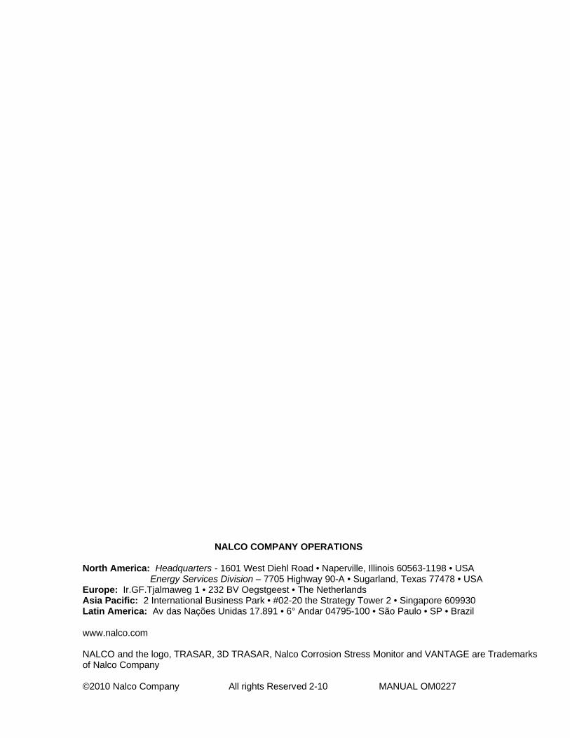
3D TRASAR Boiler Technology - Blowdown Control 101 OM0227
Nalco Global Equipment Solutions 52
NALCO COMPANY OPERATIONS
North America: Headquarters - 1601 West Diehl Road • Naperville, Illinois 60563-1198 • USA Energy Services Division – 7705 Highway 90-A • Sugarland, Texas 77478 • USA
Europe: Ir.GF.Tjalmaweg 1 • 232 BV Oegstgeest • The NetherlandsAsia Pacific: 2 International Business Park • #02-20 the Strategy Tower 2 • Singapore 609930Latin America: Av das Nações Unidas 17.891 • 6° Andar 04795-100 • São Paulo • SP • Brazil
www.nalco.com
NALCO and the logo, TRASAR, 3D TRASAR, Nalco Corrosion Stress Monitor and VANTAGE are Trademarks of Nalco Company
©2010 Nalco Company All rights Reserved 2-10 MANUAL OM0227