3d transformation - vis center projection • isometric: •angles between the projections of all...
TRANSCRIPT

3D Transformation

2
Camera Analogy
• 3D is just like taking a photograph
camera
tripod model
viewingvolume
3
Camera Analogy and
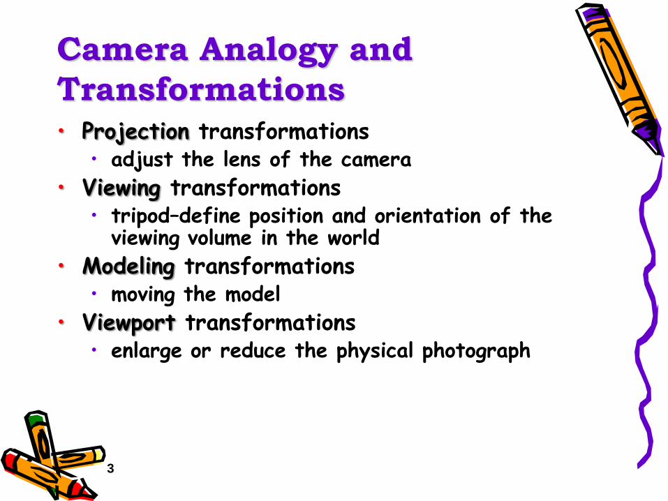
Transformations• Projection transformations
• adjust the lens of the camera
• Viewing transformations• tripod–define position and orientation of the
viewing volume in the world
• Modeling transformations• moving the model
• Viewport transformations• enlarge or reduce the physical photograph

4
Coordinate Systems and
Transformations
• Steps in Forming an Image• specify geometry (world coordinates)
• specify camera (camera coordinates)
• project (window coordinates)
• map to viewport (screen coordinates)
• Each step uses transformations
• Every transformation is equivalent to a change in coordinate systems (frames)

Tuesday, October 20, 2009 © Minglun Gong 6
3D Coordinates• Left-handed • Right-handed
X
Y
O
Z
X
Z
O
Y

Tuesday, October 20, 2009 © Minglun Gong 7
Homogeneous Coordinate
• Represent 3D point in 4D space.• (x,y,z,w)
• Normalize: (x/w,y/w,z/w,1)
• Represent 3D transformation using 4×4 matrices.
glTranslate(x,y,z)

Tuesday, October 20, 2009 © Minglun Gong 8
Translation
1000
100
010
001
,,z
y
x
zyxt
t
t
tttT
X
Y
O
Z
w
wtz
wty
wtx
w
z
y
x
z
y
x

Tuesday, October 20, 2009 © Minglun Gong 9
Scaling
1000
000
000
000
,,z
y
x
zyxs
s
s
sssS
X
Y
O
Z
w
zs
ys
xs
w
z
y
x
z
y
x
glScalef(sx, sy, sz)
Tuesday, October 20, 2009 © Minglun Gong 10
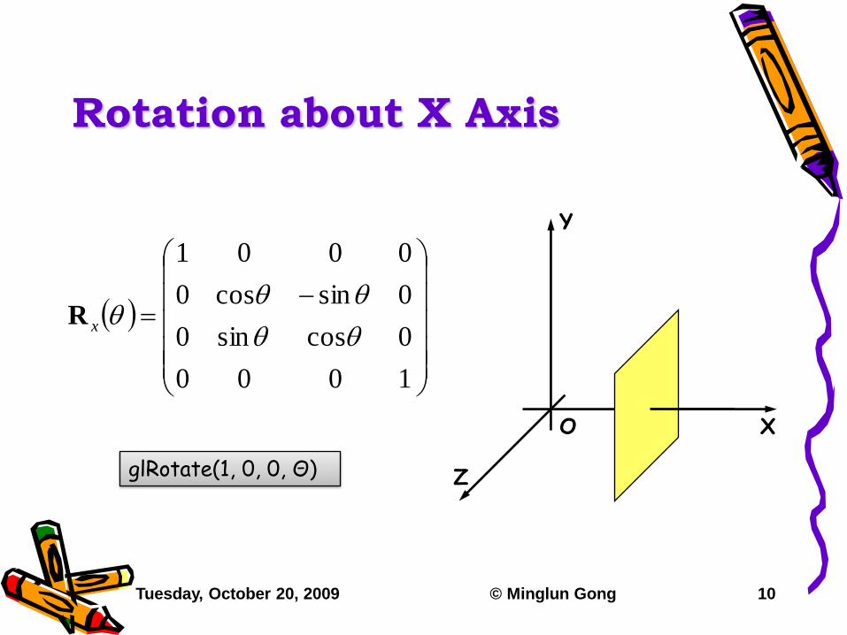
Rotation about X Axis
1000
0cossin0
0sincos0
0001
xR
X
Y
O
ZglRotate(1, 0, 0, Θ)

Tuesday, October 20, 2009 © Minglun Gong 11
Rotation about Y Axis
1000
0cos0sin
0010
0sin0cos
yR
X
Y
O
ZglRotate(0, 1, 0, Θ)

Tuesday, October 20, 2009 © Minglun Gong 12
Rotation about Z Axis
1000
0100
00cossin
00sincos
zR
X
Y
O
ZglRotate(0, 0, 1, Θ)

Tuesday, October 20, 2009 © Minglun Gong 13
3D Rotation is Not
Commutative
1000
0coscoscossinsin
0sincos0
0sincossinsincos
xy RR
1000
0coscossinsincos
0cossincossinsin
0sin0cos
yx RR
Tuesday, October 20, 2009 © Minglun Gong 14
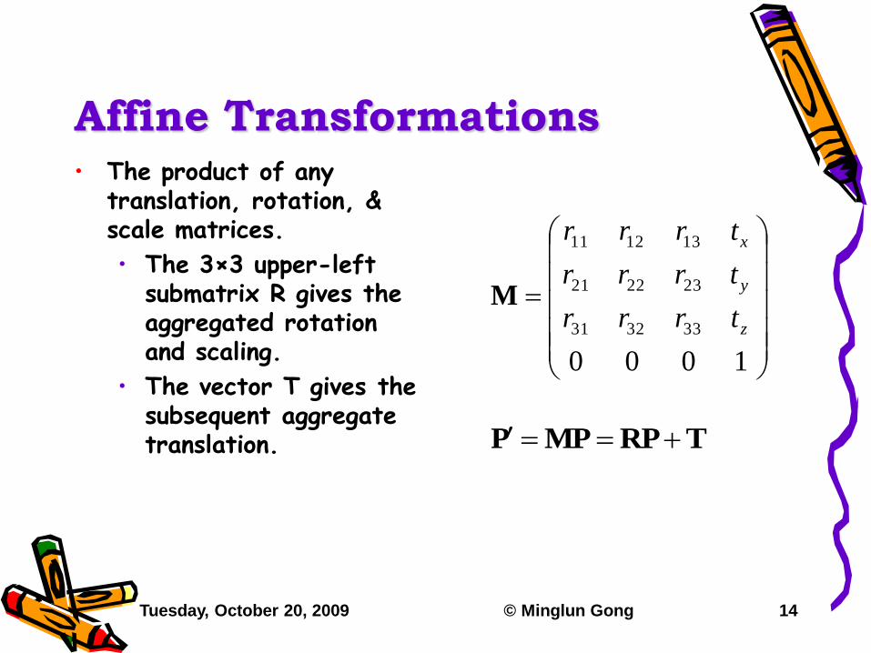
Affine Transformations• The product of any
translation, rotation, & scale matrices.
• The 3×3 upper-left submatrix R gives the aggregated rotation and scaling.
• The vector T gives the subsequent aggregate translation.
1000
333231
232221
131211
z
y
x
trrr
trrr
trrr
M
TRPMPP

Tuesday, October 20, 2009 © Minglun Gong 18
Composition of 3D
Transformations
X
Y
O
Z
P
Q
• How to rotate θ° about line PQ.• Translate P to the
origin.• Rotate about the X &
Y axis so that PQ align with Z axis.
• Rotate θ° about the Z axis.
• Rotate about the X & Y axis so that PQ return to original direction.
• Translate the origin back to point P.

3D Projection

Tuesday, October 20, 2009 © Minglun Gong 20
Outline
• Classification of different types of projections
• Parallel projection
• Perspective projection

Tuesday, October 20, 2009 © Minglun Gong 21
Projection• Geometric projection:
• Projectors are straight lines.
• Planar projection:
• Projection surface is a plane.
Projection
Geometric Non-geometric
Planar
Non-planar

Tuesday, October 20, 2009 © Minglun Gong 22
Planar Geometric Projection• Parallel:
• Different projectors parallel to each other.
• Preserve parallelism.
• Perspective:
• Different projectors converge to the center of projection.
• Does not preserve parallelism.
Planar Geometric Projection
Parallel Perspective
Orthographic
Oblique
One-point
Two-point
Three-point

Tuesday, October 20, 2009 © Minglun Gong 23
Parallel Projection• Orthographic:
• Projectors are perpendicular to the projection plane.
• Oblique:
• Projectors are NOT perpendicular to the projection plane. Projection
surface
Projectors

Tuesday, October 20, 2009 © Minglun Gong 24
Orthographic Projection• Elevation:
• Projectors are parallel to a principle axis.
• Axonometric:
• Projectors are NOT parallel to any principle axis.
Orthographic
Elevation Axonometric
Top
Front
Side
Isometric
Dimetric
Trimetric
Tuesday, October 20, 2009 © Minglun Gong 25
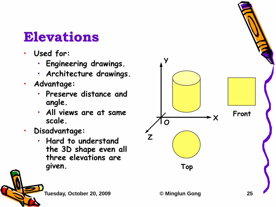
Elevations• Used for:
• Engineering drawings.• Architecture drawings.
• Advantage:• Preserve distance and
angle.• All views are at same
scale.• Disadvantage:
• Hard to understand the 3D shape even all three elevations are given.
X
Y
O
Z
Top
Front

Tuesday, October 20, 2009 © Minglun Gong 26
Matrix Representations
1000
0000
0010
0001
frontP
1000
0000
0010
0100
sideP
1000
0000
0100
0001
topP

Tuesday, October 20, 2009 © Minglun Gong 27
Axonometric Projection• Isometric:
• Angles between the projections of all three principal axes are equal (120º).
• Dimetric:
• Angles between the projections of two of the principal axes are equal.
• Trimetric:
• All three angles are different.
Isometric
Dimetric

Tuesday, October 20, 2009 © Minglun Gong 28
Isometric Projection• Used for:
• Patent office records;
• Furniture design;
• Video games (SimCity).
• Advantage:
• Illustrates 3D nature of object.
• Preserve distance along principal axes.
• Disadvantage:
• Do not preserve angle.
• Lack of foreshortening.

Tuesday, October 20, 2009 © Minglun Gong 32
Perspective Projection
Projectionsurface
Projectors
• Foreshortening effect:
• Objects further from the center of projection appear smaller.
• Vanishing point:
• Projections of parallel lines that are not parallel to the projection plane converge to a point.
Center ofProjection

Tuesday, October 20, 2009 © Minglun Gong 33
One-point & Two-point
Projections• One-point projection:
• The projection plane is parallel to two of the principle axes.
• Two-point projection:
• The projection plane is parallel to only one of the principle axes.
Tuesday, October 20, 2009 © Minglun Gong 34
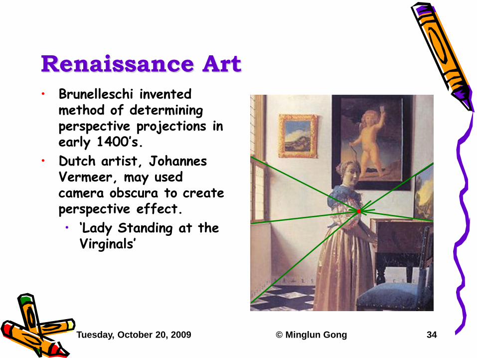
Renaissance Art• Brunelleschi invented
method of determining perspective projections in early 1400‟s.
• Dutch artist, Johannes Vermeer, may used camera obscura to create perspective effect.
• „Lady Standing at the Virginals‟

Tuesday, October 20, 2009 © Minglun Gong 35
Matrix Representation I• Configuration:
• The center of projection is placed at (0,0)
• The function for projection plane is z=f:
• For 3D point (x,y,z,1):
• w = z / f;
• u = x / w = x * f / z
• v = y / w = y * f / z
0100
0100
0010
0001
f
P
f
Projectionplane
Z
X
u(x,z)
Center ofProjection

Tuesday, October 20, 2009 © Minglun Gong 36
Matrix Representation II• Configuration:
• The center of projection is placed at (0,-f);
• The function for projection plane is z=0:
• For 3D point (x,y,z,1):
• w = z / f + 1;
• u = x / w
• = x * f / (z + f)
• v = y / w
• = y * f / (z + f)
1100
0000
0010
0001
f
P
f
Projectionplane
Z
X
u(x,z)
Center ofProjection
3D Viewing

Tuesday, October 20, 2009 © Minglun Gong 38
Outline
• View specification.• Steps involved in 3D viewing.
• Coordinate systems.
• Camera parameters.
• View volume.• Clipping planes.

Tuesday, October 20, 2009 © Minglun Gong 39
View Specification
• A popular way is to specify a virtual camera in the 3D scene.
• How to specify a virtual camera?• External parameters:
• Specify the position and orientation of the camera.
• Internal parameters:
• Specify how the scene is projected onto an image.

Tuesday, October 20, 2009 © Minglun Gong 40
Steps Involved
View Volume Clipping
3D Trans-formation
World coordinates
3D Projection
Camera coordinates
Screen coordinates
External parameters
Internal parameters
2D Trans-formation
Raster coordinates

Tuesday, October 20, 2009 © Minglun Gong 41
Camera Coordinate System• Also called:
• View-reference coordinate system;
• Eye coordinate system.
• Settings:
• Left hand system.
• The center of projection is at origin;
• The camera looks toward +Z;
• X is to the right and Y is up.
Z´
Y´
X
Y
Z
X´

Tuesday, October 20, 2009 © Minglun Gong 42
Screen Coordinate System• Also called:
• Normalized-projection coordinate system;
• Settings:
• All visible objects are projected into a normalized window;
• All the coordinate values are within the interval: [-1,1].
X
Y
1-1
-1
1

Tuesday, October 20, 2009 © Minglun Gong 43
Raster Coordinate System• Also called:
• Device coordinate system.
• Settings:
• The range of the coordinate values depends on the resolution.
X
Y
width
heigh
t

Tuesday, October 20, 2009 © Minglun Gong 44
External Parameters• Position:
• Center of projection: C
• Orientation:
• View direction: V
• Up direction: U
• The camera coordinate system:
• Z´ = V
• X´ = V × U
• Y´ = X´ × V
V(Z´)
C
Y´
X
Y
Z
X´
U

Tuesday, October 20, 2009 © Minglun Gong 45
3D Transformation Defined
• Transformation from world coordinates to camera coordinates is the composition of the following transformations:• Translate by –C, bring the center of projection
to origin;
• Rotate about X & Y axes so that V align with Z axis;
• Rotate about Z axis so that U lies on Y-Z plane.
• Transformation from camera coordinates to world coordinates is the reverse matrix.

Tuesday, October 20, 2009 © Minglun Gong 46
Internal Parameters
w
• Focal length:
• Distance between the center of projection and the projection plane: f.
• 50mm for “standard” lens.
• Image (film) size:
• Width & height: 2w×2h.
• 36×24mm for 35mm film.
• Field of view:
• Angle: θh, θv.
• tan(θh/2) = w/f.

Tuesday, October 20, 2009 © Minglun Gong 47
3D Projection Defined
11
f
wzyf
wzxf
fz
z
wy
wx
z
y
x
0100
0100
0010
0001
f
w
w
P
1
1
1
f
wh
f
h
w

Tuesday, October 20, 2009 © Minglun Gong 48
Clipping
• Points on the z=0 plane cannot be projected.• The weight is zero after projection.
• Mapped to infinity.
• Have to eliminate the potion of scene that is behind the viewpoint before projection.
• To cut computational cost, we can also eliminate all objects that are outside the viewing volume.

Tuesday, October 20, 2009 © Minglun Gong 49
View Volume• Defines:
• The portion of the world that projects onto the projection plane.
• Perspective projection
• Truncated pyramid.
• Parallel projection
• Parallelepiped.
X
Y
Z

Tuesday, October 20, 2009 © Minglun Gong 50
Clipping Planes
X
Y
Z
Front clipping plane
Back clipping plane
• Front clipping plane:
• Also called near clipping plane or hither plane.
• Remove objects that are behind or too close to the center of projection.
• Back clipping plane:
• Also called far clipping plane or yon plane.
• Sometime at infinite.
• Remove objects that are too far away and the projection are too small.

Tuesday, October 20, 2009 © Minglun Gong 51
Clipping Planes (Cont’d)• Surrounding planes:
• Defined by the four edges of the image.
• It is difficult to do clipping in the camera coordinates.
• Clipping can be done after projection.
X
Y
Z

52
Transformations in OpenGL
• Modeling
• Viewing• orient camera
• projection
• Animation
• Map to screen

55
3D Transformations
• A vertex is transformed by 4 x 4 matrices• all affine operations are matrix
multiplications• all matrices are stored column-major in
OpenGL• matrices are always post-multiplied• product of matrix and vector is
v
M
151173
141062
13951
12840
mmmm
mmmm
mmmm
mmmm
M

56
Specifying Transformations• Programmer has two styles of specifying
transformations• specify matrices (glLoadMatrix, glMultMatrix)
• specify operation (glRotate, glOrtho)
• Programmer does not have to remember the exact matrices• check appendix of Red Book (Programming
Guide)

57
Programming
Transformations
• Prior to rendering, view, locate, and orient:• eye/camera position
• 3D geometry
• Manage the matrices• including matrix stack
• Combine (composite) transformations

58
vertex
Modelview
Matrix
Projection
Matrix
Perspective
Division
Viewport
Transform
Modelview
Modelview
Projection
l
l
l
object eye clip normalized
devicewindow
• other calculations here• material color• shade model (flat)• polygon rendering mode• polygon culling• clipping
Transformation
Pipeline CPU DL
Poly.Per
Vertex
Raster Frag FB
Pixel
Texture

59
Matrix Operations
• Specify Current Matrix Stack
• Other Matrix or Stack Operations
• Viewport• usually same as window size• viewport aspect ratio should be same as
projection transformation or resulting image may be distorted
60
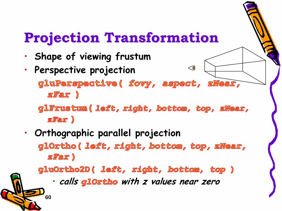
Projection Transformation
• Shape of viewing frustum
• Perspective projection
• Orthographic parallel projection
• calls with z values near zero

61
Applying Projection
Transformations
• Typical use (orthographic projection)glMatrixMode( GL_PROJECTION );
glLoadIdentity();
glOrtho( left, right, bottom, top, zNear, zFar );
62
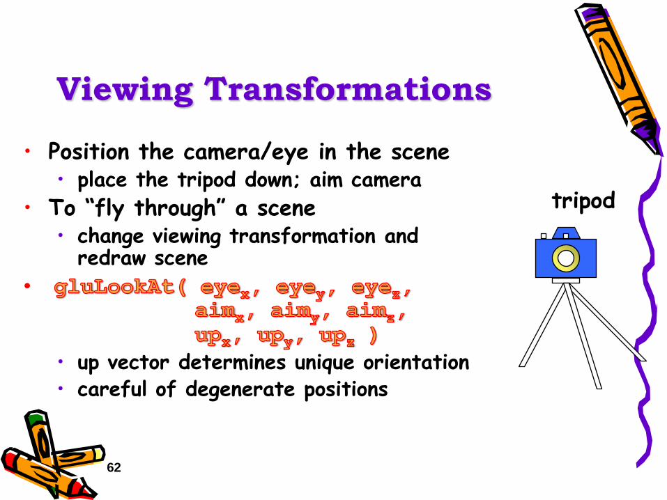
Viewing Transformations
• Position the camera/eye in the scene• place the tripod down; aim camera
• To “fly through” a scene• change viewing transformation and
redraw scene
•
• up vector determines unique orientation• careful of degenerate positions
tripod

63
Projection Tutorial

64
Modeling Transformations
• Move object
• Rotate object around arbitrary axis
• angle is in degrees
• Dilate (stretch or shrink) or mirror object
zyx

65
Transformation Tutorial

66
Connection: Viewing and
Modeling
• Moving camera is equivalent to moving every object in the world towards a stationary camera
• Viewing transformations are equivalent to several modeling transformationsgluLookAt() has its own command
can make your own polar view or pilot view

67
Projection is left handed
• Projection transformations (gluPerspective, glOrtho) are left handed• think of zNear and zFar as distance from view
point
• Everything else is right handed, including the vertexes to be rendered
xx
yy
z+
z+
left handed right handed

68
Common Transformation
Usage
• Examples of resize() routine
• restate projection & viewing transformations
• Usually called when window resized
• Registered as callback

69
resize(): Perspective &
LookAtvoid resize( int w, int h ){
glViewport( 0, 0, (GLsizei) w, (GLsizei) h );glMatrixMode( GL_PROJECTION );glLoadIdentity();
gluPerspective( 65.0, (GLfloat) w / h,
1.0, 100.0 );glMatrixMode( GL_MODELVIEW );glLoadIdentity();
gluLookAt( 0.0, 0.0, 5.0, 0.0, 0.0, 0.0, 0.0, 1.0, 0.0 );
}

71
resize(): Ortho (part 1)
void resize( int width, int height )
{
GLdouble aspect = (GLdouble) width / height;
GLdouble left = -2.5, right = 2.5;
GLdouble bottom = -2.5, top = 2.5;
glViewport( 0, 0, (GLsizei) w, (GLsizei) h );
glMatrixMode( GL_PROJECTION );
glLoadIdentity();
… continued …

72
if ( aspect < 1.0 ) {
left /= aspect;
right /= aspect;
} else {
bottom *= aspect;
top *= aspect;
}
glOrtho( left, right, bottom, top, near, far );
glMatrixMode( GL_MODELVIEW );
glLoadIdentity();
}
resize(): Ortho (part 2)