3d scanning instruments€¦ · recap multi-view stereo reconstruction • advantages • cheap (no...
TRANSCRIPT

Optical Active 3D
Scanning
Gianpaolo Palma

3D Scanning Taxonomy
SHAPE ACQUISTION
CONTACT NO-CONTACT
NO
DESTRUCTIVEDESTRUCTIVE
CMM ROBOTIC
GANTRYSLICING
OPTICALMAGNETIC
X-RAY ACOUSTIC
ACTIVE PASSIVE

Recap
Computational Tomography and
Magnetic Resonance
• Advantages
• A complete model is returned in a single shot,
registration and merging not required
• Output: volume data, much more than just an exterior
surface
• Disadvantages
• Limitation in the size of the scanned object
• Cost of the device
• Output: no data on surface attributes (e.g. color)

Recap
Multi-View Stereo Reconstruction
• Advantages
• Cheap (no scanning device needed), fast tech evolution
• Good flexibility (both small and huge model can be acquired)
• Cameras are more easy to use than a scanner (lighter, no
tripod, no power, multiple lenses …)
• Non-expert users can create 3D models
• Disadvantages
• Accuracy (not so accurate, problems with regions with
insufficient detail)
• Slower than active techniques (many images to process and
merge)
• Not all the objects can be acquired

Active Optical Tecnology
• Advantages
• Using active lighting is much faster
• Safe - Scanning of soft or fragile objects which would be
threatened by probing
• Set of different technologies that scale with the object
size and the required accuracy
• Disadvantages
• Can only acquire visible portions of the surface
• Sensitivity to surface properties (transparency, shininess,
darkness, subsurface scatter)
• Confused by interreflections

Active Optical Tecnology
• Active optical vs CT scanner
• Cheaper, faster, scale well with object size
• But no volume information and more processing
• Active optical vs Multi-view stereo
• Faster and more accurate
• But more expensive and more user expertise
Active Optical Tecnology
• Depth from Focus
• Confocal microscopy
• Interferometry
• Triangulation
• Laser triangulation and structured light
• Time-of-Flight
• Pulse-based and Phase-based

Why different active optical
tecnology?
[Drouin et al., 2012]

Confocal Microscopy
[Drouin et al., 2012]

Confocal Microscopy
• Increase the optical
resolution and contrast of
microscope by placing a
pinhole at the confocal
plane of the lens to
eliminate out-of-focus light
• Controlled and highly
limited depth of focus.
• 3D reconstruction with
images captured at different
focal plane

Confocal Microscopy
• Scanning mirrors that can move the laser beam very precisely and quickly (one mirrors tilts the beam in the X direction, the other in the Y direction)
• Z-control focus on any focal plane within your sample allowing movement in the axial direction with high precision (>10 nm).

Confocal Microscopy
Image by Wikipedia
CC BY-SA 3.0

Interferometry
[Drouin et al., 2012]

Inteferometry
• General Idea - Superimposing waves causing the
phenomenon of interference. To extract information
from the resulting waves.

Michelson Interferometer• Single source split into two beams that travel different path,
then combined again to produce interference
• Information about the difference in the path by analyzing
the interference fringes
Image by Wikipedia
CC BY-SA 3.0
Image by Wikipedia CC BY-SA 3.0

White Light Interferometry
• Accurate movement of objective
in the z axial direction to change
length of beam path
• Find the maximum modulation
of the interference signal for
each pixel

White Light Interferometry
[Peter de Groot, 2015]

Conoscopic Holography
[Drouin et al., 2012]

Conoscopic Holography
Birefringent crystal
• The refractive index depends on the polarization and propagation direction of light. The refractive index in one crystal axis (optical axis) is different from the other.
• Splitting of the incident ray in two ray with different path according polarization
• Ordinary ray (a constant refractive index)
• Extraordinary ray (the refractive index dependson the ray direction)

Conoscopic Holography
• Analyzing the interference pattern of ordinary and
extraordinary waves of the beam reflect by the
measured same

Conoscopic Holography

Laser Triangulation
[Drouin et al., 2012]
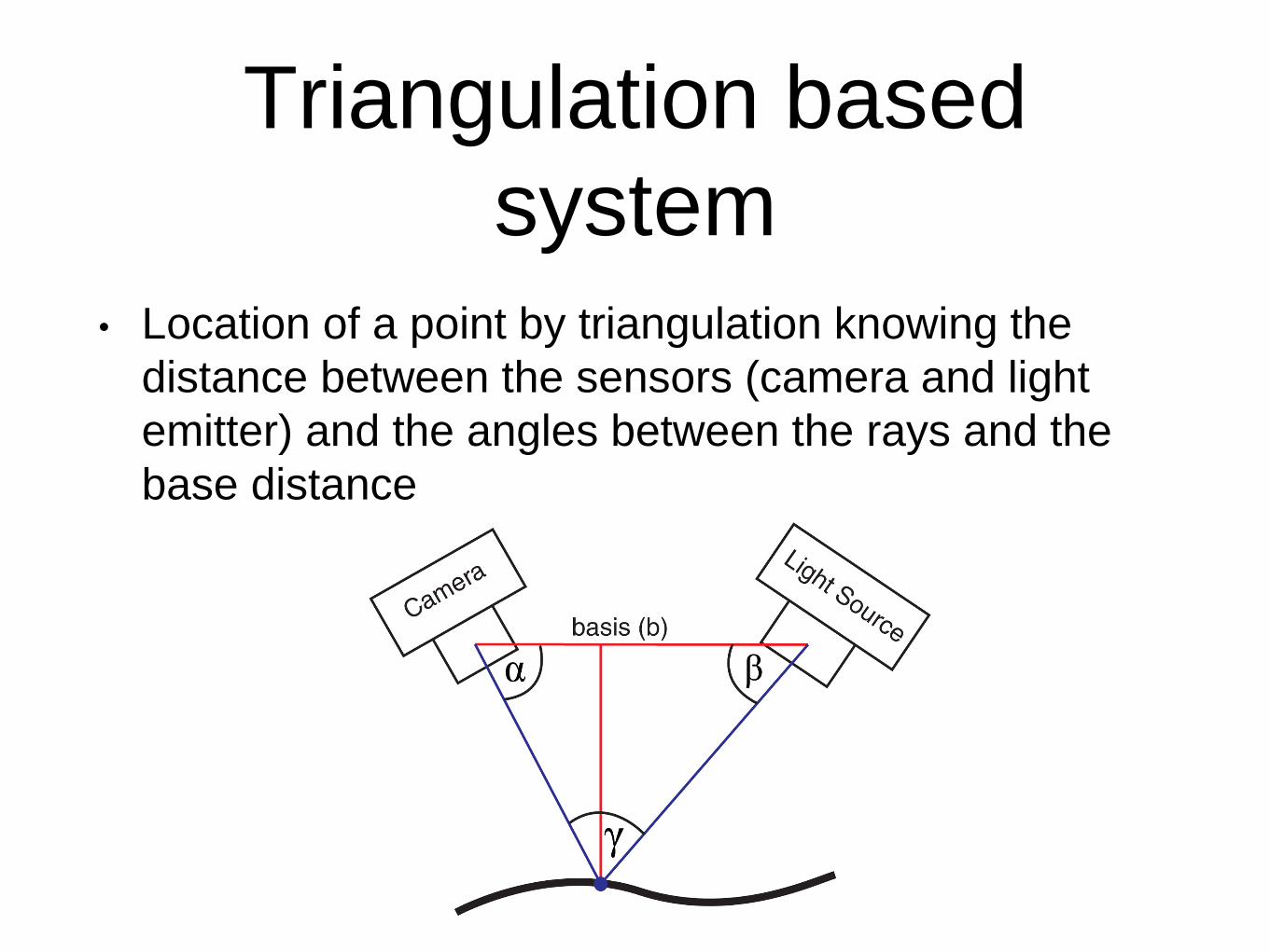
Triangulation based
system• Location of a point by triangulation knowing the
distance between the sensors (camera and light
emitter) and the angles between the rays and the
base distance

Triangulation based
system• An inherent limitation of the
triangulation approach: non-visible regions
• Some surface regions can be visible to the emitter and not-visible to the receiver, and vice-versa
• In all these regions we miss sampled points
• Need integration of multiple scans

Conoscopic Holography vs
Triangulation
CONOSCOPIC HOLOGRAPHY TRIANGULATION

Mathematics of
triangulationParametric representation of lines and rays
Parametric and implicit representation of a plane
[Douglas et al.,
SIGGRAPH 2009]
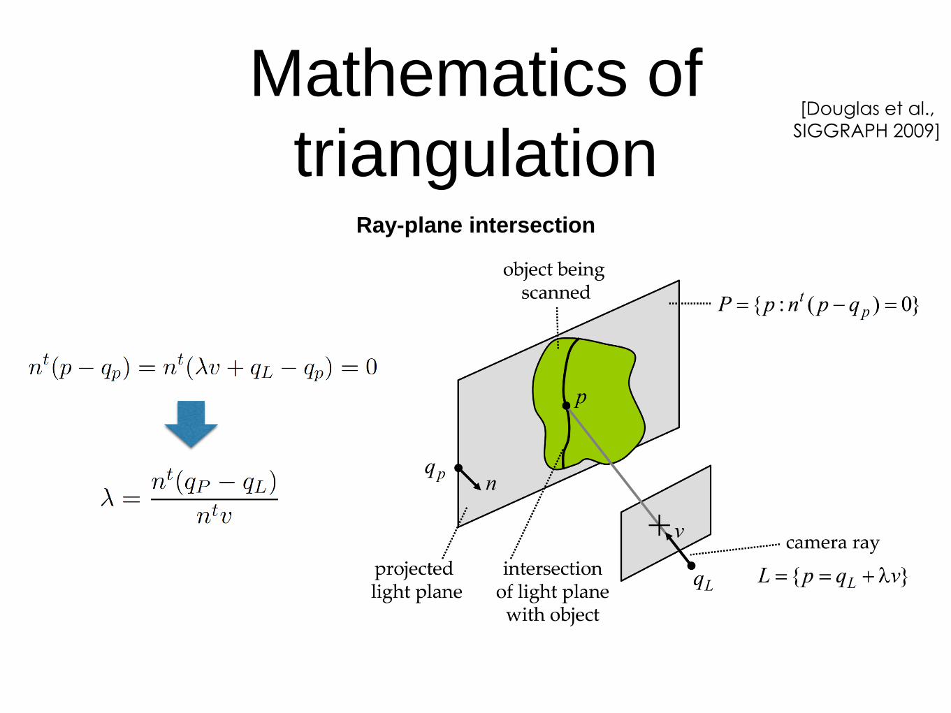
Mathematics of
triangulationRay-plane intersection
[Douglas et al.,
SIGGRAPH 2009]

Mathematics of
triangulationRay-ray intersection
Intersection that
minimizes the sum
of the squared
distance to both
the rays
[Douglas et al.,
SIGGRAPH 2009]
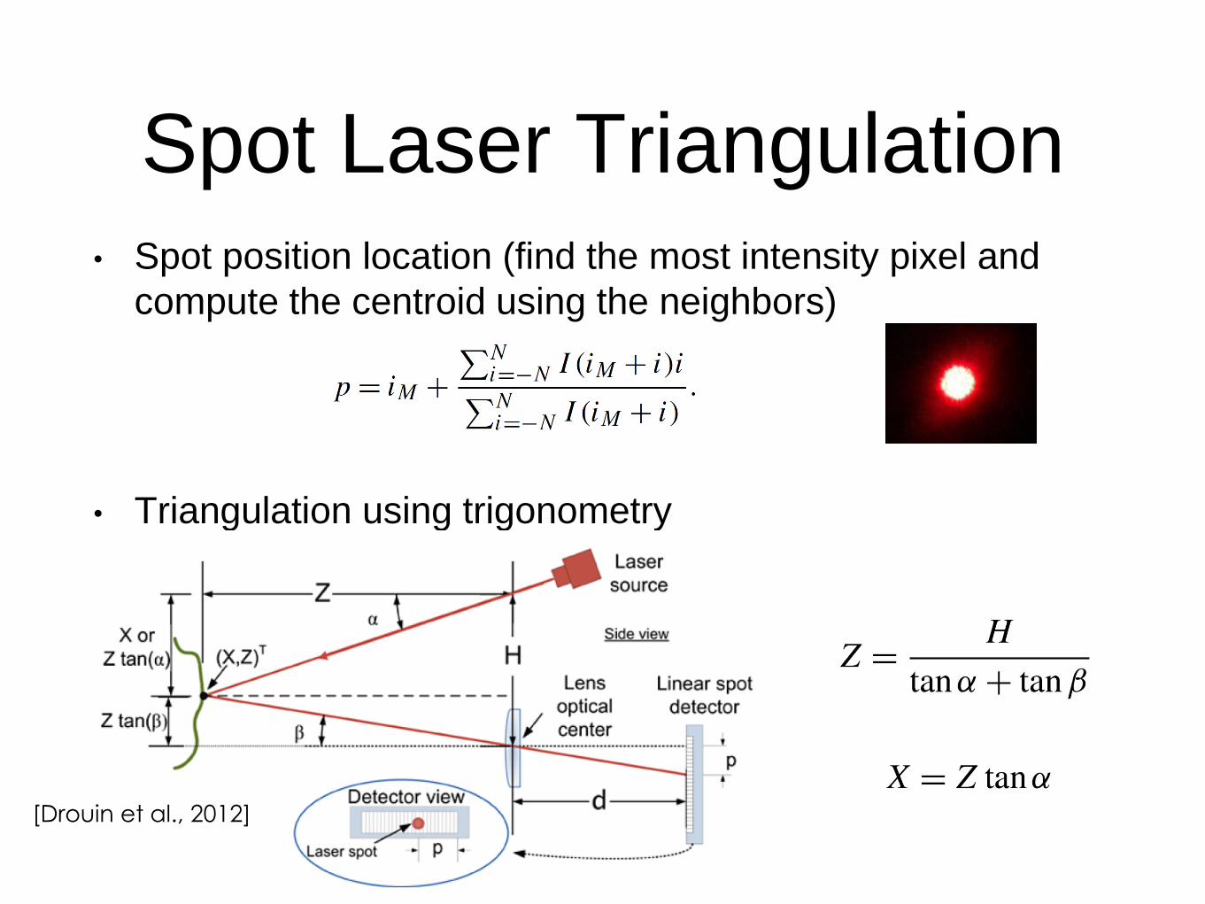
Spot Laser Triangulation• Spot position location (find the most intensity pixel and
compute the centroid using the neighbors)
• Triangulation using trigonometry
[Drouin et al., 2012]

Laser Line Triangulation
• Laser projector and camera modelled as a pinhole camera
• Detection of the pixel in the laser line with computer vision algorithm (peak detection)
• Ray-plane triangulation [Blais, 2004]

Laser Line Triangulation
• Rotate or translate the scanner or rotate the object
using a turntable
• be rotated on a turntable
[Drouin et al., 2012]

Errors in Triangulation
system
[Curless et al., ICCV 1995]
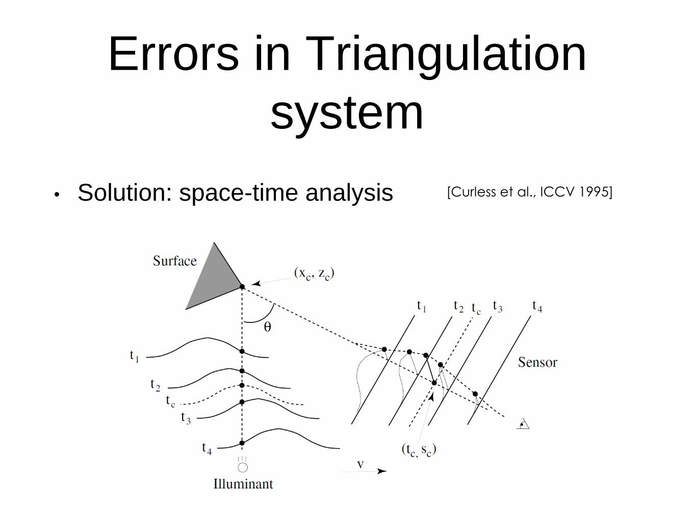
Errors in Triangulation
system
• Solution: space-time analysis [Curless et al., ICCV 1995]

Errors in Triangulation
system
• Solution: space-time analysis [Curless et al., ICCV 1995]

Structured Light
[Drouin et al., 2012]

Structured light scanner
• Projection of light pattern using a digital projector
and acquisition of its deformation with one o two
cameras
[Drouin et al., 2012]

Structured light scanner
• Simple design, no sweeping/translating devices needed
• Fast acquisition (a single image for each multi-stripe
pattern)
• Ambiguity problem with a single pattern to identify which
stripe light each pixel

Structured light scanner
• How to solve the ambiguity?
• Many coding strategies that can be used to recover which camera pixel views the light from a given plane
• Temporal coding – Multiple patterns in the time, matching using the time sequence of the image intensity, slower but more accurate
• Spatial coding – A single pattern, the local neighborhood is used to perform the matching, more suitable for dynamic scene
• Direct coding – A different code for every pixel

Temporal CodingBinary Code
• Two illumination levels: 0 and 1
• Every point is identified by the
sequence of intensities that it receives
• The resolution is limited to half the size
of the finest pattern

Temporal Coding
• Binary Code
• Gray Code – Neighboring columns differ by one bit then more
robust to decoding error

Temporal Coding
• Location of the stripes
• Simple thresholding - Per-pixel threshold as average of
two images acquired with all-white and all-black patterns
– Pixel accuracy

Temporal Coding
• Location of the stripes
• Projection of Gray code and reserve Gray code and
intersection of the relative intensity profile- Sub-pixel
accuracy
[Drouin et al., 2012]

Temporal Coding
• N-ary code – Reduce the number of patterns by
increasing the number of intensity levels used to
encode the stripes.
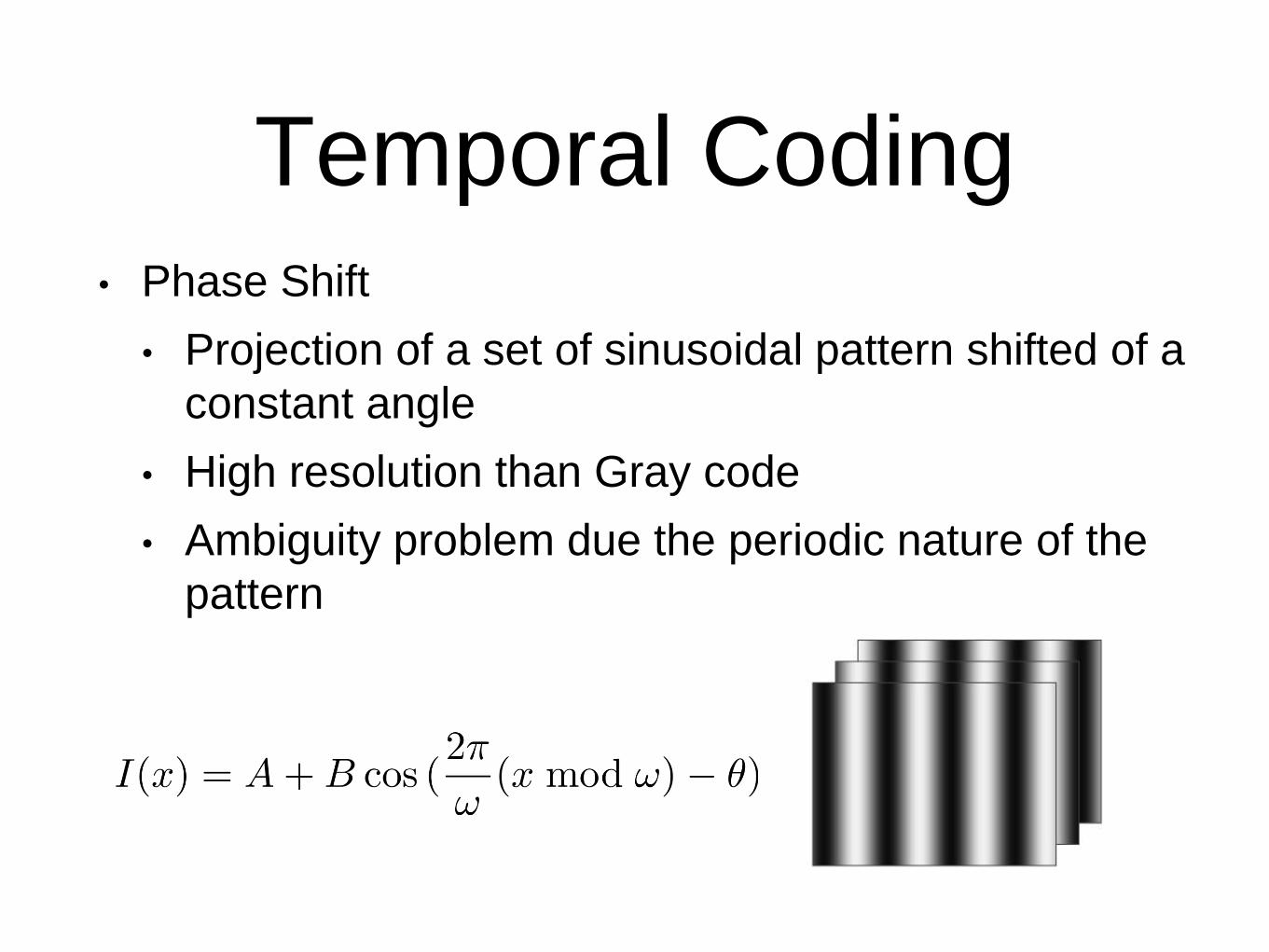
Temporal Coding• Phase Shift
• Projection of a set of sinusoidal pattern shifted of a
constant angle
• High resolution than Gray code
• Ambiguity problem due the periodic nature of the
pattern

Temporal Coding• Gray Code + Phase Shift
• Corse correspondence projector-camera with Gray code
to remove ambiguity
• Refinement with phase shift
• Problem with non-constant albedo surface
[Gühring , 2000]

Temporal Coding
• Gray Code + Line Shift
• Substitution the sinusoidal pattern with a pattern of
equally spaced vertical line
[Gühring , 2000]

Spatial Coding
• The label of a point of the pattern is obtained from a
neighborhood around it.
• The decoding stage more difficult since the spatial
neighborhood cannot always be recovered (fringe
not visible from the camera due to occlusion) [Zhang et al.,
3DPVT 2002]

Direct Coding• Every encoded pixel is identified by its own
intensity/color
• The spectrum of intensities/colors used is very large
• Sensible to the reflective properties of the object,
low accuracy, need accurate calibration
RAINBOW PATTERN GREY LEVEL SCALE
PATTERN

Time of Flight
[Drouin et al., 2012]

Pulse-based Time of Flight
Scanning• Measure the time a light impulse needs to travel from emitter to
target
• Source: emits a light pulse and starts a nanosecond watch (1m
= 6.67ns
• Sensor: detects the reflected light, stops the watch (roundtrip
time)

Pulse-based Time of Flight
Scanning
• Scanning
• Single spot measure
• Range map obtained by rotating mirrors
or motorized 2 DOF head
• Advantages
• No triangulation, source and detector on
the same axis (no shadow effect)

Phase-based Time of
Flight Scanning• A laser beam with sinusoidal modulated optical
power is sent to a target. The phase of the reflected
light is compared with that of the sent light

Phase-based Time of
Flight Scanning
• Ambiguity of the phase shift. When , the
unambiguous distance measurement is limited to (e.g.
with frequency 16.66 MHz a maximum distance of 9m)
[Foix et al., 2011]

Time of Flight Scanning
In principle is an easy approach, but:
• maximum distance range limited by the amount of light
received by the detector (power of the emitter, environment
illumination)
• accuracy depends on : optical noise, thermal noise, ratio
between reflected signal intensity and ambient light intensity
• Accurate and fast systems are still expensive (70K-100K
Euro)
• Cost depends on mechanical components (high-quality
rotation unit, to span the spherical space around the
scanner)

References• de Groot, Peter J. "31 Interference Microscopy for Surface Structure Analysis." (2015).
• Gava, Didier, and Francoise J. Preteux. "3D conoscopic vision." Optical Science, Engineering
and Instrumentation'97. International Society for Optics and Photonics, 1997.
• Blais, François. "Review of 20 years of range sensor development." Journal of Electronic
Imaging 13.1 (2004): 231-243.
• Salvi, Joaquim, Jordi Pages, and Joan Batlle. "Pattern codification strategies in structured light
systems." Pattern recognition 37.4 (2004): 827-849.
• Lanman, Douglas, and Gabriel Taubin. "Build your own 3D scanner: 3D photography for
beginners." ACM SIGGRAPH 2009 Courses. ACM, 2009.
• Curless, Brian, and Marc Levoy. "Better optical triangulation through spacetime analysis."
Computer Vision, 1995. Proceedings., Fifth International Conference on. IEEE, 1995.
• Drouin, Marc-Antoine, and Jean-Angelo Beraldin. "Active 3D Imaging Systems." 3D Imaging,
Analysis and Applications. Springer London, 2012. 95-138.
• Foix, Sergi, Guillem Alenya, and Carme Torras. "Lock-in time-of-flight (ToF) cameras: A
survey." IEEE Sensors Journal 11.9 (2011): 1917-1926.
• Gühring, Jens. "Dense 3D surface acquisition by structured light using off-the-shelf
components." Photonics West 2001-Electronic Imaging. International, 2000.
• Zhang, Li, Brian Curless, and Steven M. Seitz. "Rapid shape acquisition using color structured
light and multi-pass dynamic programming." 3D Data Processing Visualization and
Transmission, 2002.