3d real time visualization for support of archaeological analysis
TRANSCRIPT

3D REAL TIME VISUALIZATION FOR SUPPORT OF ARCHAEOLOGICAL ANALYSIS
Martin Sauerbier
Institute of Geodesy and Photogrammetry, Chair of Photogrammetry and Remote SensingETH Zurich
Wolfgang-Pauli-Strasse 15, 8093 Zurich, [email protected]
http://www.photogrammetry.ethz.ch
KEY WORDS: Archaeology, DEM/DTM, Multiresolution, Orthoimage, Virtual Reality, Visualization
ABSTRACT:
Within the longterm research project Nasca/Palpa, which has been conducted at the group of photogrammetry and remote sensing ofETH Zurich since 1997, an archaeological GIS-database describing the famous ground drawings of thePalpa region and a wide varietyof terrain data and orthoimages were produced at different levels in terms of accuracy and spatial resolution. In order to visualize thesedata in a real time 3D environment, the Skyline Terra Builderand Explorer Pro software packages were chosen due to their capabilitiesof integration of different layers with different resolutions. A second important feature of the used software is the option to enhancethe spatial content by further elements, such as still and dynamic 2D and 3D objects, QuicktimeTM -panoramas and -movies, labels andflight paths, by means of an integrated scene description language. In our case, these options were used to add results from GIS-basedanalyses applied to the geoglyphs in Palpa, e.g. visibilitystudies, and to verify them inside the 3D environment.
1 INTRODUCTION
Since 1997, the Institute of Geodesy and Photogrammetry (IGP)at ETH Zurich is actively involved in the transdisciplinaryre-search project Nasca/Palpa in cooperation with the Commissionfor Archaeology of Non-European Cultures Bonn of the Ger-man Archaeological Institute (DAI-KAAK). During this period,several photogrammetric and GIS-related sub-projects were ac-complished at our institute in order to support archaeological re-search by means of generation of photogrammetric products suchas DTMs, DSMs, orthoimages and 3D topographic vector data.A second field of research was the development of methods andsoftware for GIS-based analyses adapted to investigationson thefunction and meaning of the famous geoglyphs, the so-called”Nasca Lines”. Over the years, a comprehensive collection ofdifferent data sets was generated and so far was only visualizedin standalone modes (Lambers and Sauerbier, 2003, Lambers etal., 2007, Sauerbier, 2008) or in partly integrated visualizations(Sauerbier et al., 2006) using point-based rendering. Further-more, results of analyses were not included in 3D visualizationsaside from still views generated in GIS-software (Lambers,2006,p. 113-115).The goal of the work presented here does not focus on the visual-ization performance of a certain software, but proposes conceptshow to apply 3D visualization as a tool for archaeological workbeyond mere presentation purposes. A performance evaluation ofthe here applied software in comparison with a 3D graphics en-gine from the game development domain conducted recently byour group will be published elsewhere.
1.1 Area of investigation
The area of investigation is located in Peru, approximately400km south ofLima. The spatial extent of the produced data cov-ers an area of 13.350 km2 from the modern city ofIca in thewest to the Andes east of the city ofNasca and from the southcoast aroundMonte Grande to the Andes villageCorontayo inthe north. The region contains a rich cultural heritage in termsof settlement and cemetery sites (Reindel et al., 2001, Sossna,2007), monuments (Silverman, 1993), geoglyphs (Kosok and Re-iche, 1949, Aveni, 1990, Reindel, 2007, Lambers, 2006) and pet-
roglyph sites (Pavelka, 2007, Fux et al., 2008a, Fux et al., 2008b,Sauerbier et al., 2008) which are since the 1920s subject of ar-chaeological research.
Figure 1 illustrates the area of investigation.
Figure 1: The area of investigation in south Peru
1.2 Available data
The terrain, orthoimage and vector data available within our projectand the according procedures for their generation were alreadydescribed in detail elsewhere (Lambers, 2006, Lambers et al.,2007, Sauerbier, 2008, Lambers and Sauerbier, 2006), thereforetables 1 and 2 give a brief overview of the image and terrain data
utilized for the work presented here. In addition to the raster data,the mapped geoglyphs were available as a 3D vector data set inpolygonal representation. All spatial data refer to the UTMZone18 S with the WGS-84 ellipsoid as horizontal and vertical datum.The whole data set features approximately 50 GB, with 48 GB ofimage data and 2 GB of terrain data in uncompressed formats.
Table 1: DTM data generated within the Nasca/Palpa projectData set Grid Method of GenerationDSM Pinchango Alto 10 cm UAV imagesDSM Pinchango Alto 5 cm Terrestrial laser scanningDTM Palpa 2 m Aerial images 1:7’000DTM Pampa de Nasca 5 m Aerial images 1:10’000DSM Nasca Region 30 m ASTER satellite imagery
Table 2: Orthoimage data generated within the Nasca/Palpaproject
Data set FootprintOrthoimage Pinchango Alto 3 cmOrthoimage Palpa 28 cmOrthoimage Pampa de Nasca15 cmOrthoimage Nasca Region 30 m
2 3D VISUALIZATION USING SKYLINE
The Skyline Terra Builder (version 1) and Explorer Pro (version3) software package (Skylinesoft Inc.) is a real time visualizationtool specialized on 2,5D terrain data with texture, though it offersthe option to import also real 3D objects such as buildings andothers from CAD data formats (DXF, ESRI shapefiles).
2.1 Integration of multiresolution data
The procedure of integrating layers of different resolution intothe 3D model was accomplished using the Terra Builder. In afirst step, all data had to be imported to the proprietary datafor-mat, then for each layer a bounding polygon could be definedin order to determine the part that should be included in the fi-nal 3D model. For multiresolution layers, a small overlap be-tween neighboring layers is recommended to take advantage ofthe feathering function which provides for smooth transition be-tween layers of different resolution, be it geometric data or tex-ture. Thus, a visually highly qualitative visualization ofthe mul-tiresolution data could be obtained as figure 2 illustrates,thoughno information was published by the software developers on themethods implemented to handle the overlapping regions, or to bemore precise it is not clear how Skyline processes a) the DTMand b) the orthoimage data in these regions.Figure 2 shows a subset of the multiresolution 3D model, in par-ticular one can distinguish the outer part, where the underlyingDTM Palpa (cp. 1) features a grid size of 2 m and the B/W or-thoimage Palpa (cp. 2) has a footprint of 0.28 m, and the innerpart where the DSM Pinchango Alto (cp. 1) generated from UAVimages with 0.1 m grid size and the orthoimage Pinchango Alto(cp. 2) with 0.03 m footprint are displayed. 1
2.2 The integrated scene description language
The Terra Explorer allows to store the files, which define the be-haviour of the 3D model during the navigation and the furthercontents, in binary (.FLY) or ASCII (.TEH) formats. While thefirst can be edited in a user-friendly way inside the Terra Ex-plorer, the second due to its nature being an ASCII file can beedited arbitrarily with the advantage that some of the features canbe generated repeatedly by scripting. The following features ofthe resulting visualization environment can be controlledvia theTEH file:
• The 3D visualization container: maximum viewing distance,fog distance and color, start position and attitude of the vir-tual camera.
• The flight model: min./max. speed in all coordinate di-rections and in rotation, acceleration and deaccelerationforspeed and rotations, min./max. altitude, min./max. zoomlevel.
• Containers for info tree, web page, logos, and 3D and geo-referenced map display.
• Locations: allows to store points of interest as quickly ac-cessible viewpoints.
• Routes: flight paths, which can be recorded as video files.
• 2D primitives: a set of predefined primitives 3.
• 3D primitives: a set of predefined 3D primitives.
• Image placement inside the 3D model (JPG, BMP, GIF).
• Labels allows to place textual labels, e.g. toponyms, insidethe 3D model.
• Dynamic objects: this function can be used to place 3D ob-jects in the model by giving them a defined route that theymove along. These objects are allowed to either move onthe terrain or to fly and can be linked to each other.
• Layers allows to import and display (or switch off) DXFlayers.
• Messages allows to display text messages in a separate con-tainer.
Inside the scene description file, a flag denotes which type ofob-ject is described in the next section, then in a defined order typ-ical for each object the parameters which control its display arestored.For our purpose - the enhancement of the 3D model with archae-ological information and results - various of these functions canbe employed (compare 2.3). 1
2.3 Integration of analysis results
One example are remains of wooden posts found on several trape-zoidal geoglyphs nearPalpa which featured a height of approx-imately 4-5 m over ground and were used as target features ina visibility study (Lambers, 2006). Figure 4 shows the viewshedfor a post found on theCresta de Sacramento in the west ofPalpa.
Using the 3D primitives, in this case a cylinder, the known postscould be integrated into our textured 3D model with differentheights such that a visual verification of the results of the view-shed calculations was enabled. Additionally, the according view-shed rasters were vectorized and integrated as well as a 2D poly-gon layer which overlays the terrain transparently.A second type of result from GIS-based analyses which was in-tegrated into the 3D model were lines of sight determined frominvestigations on geoglyph orientations (Lambers and Sauerbier,2008), in particular with respect to mountain peaks. In thiscase, avisual verification of the results using the 3D model is of greatim-portance due to the fact that the orientation computations implyuncertainties caused by geoglyph mapping accuracy, DTM accu-racy and uncertainty of the mountain peak definition and its rep-resentation by the DTM. Visual verification therefore serves asan additional source of information in order to classify geoglyphs

Figure 2: 3D view towards the pre-Inka settlement site of Pinchango Alto. The central settlement area features a DSM gridsize of 10cm and an orthoimage footprint of 3 cm while the surrounding area is covered by a DTM which provides a grid size of 2 m and 28 cmorthoimage footprint.
Figure 3: Example for Terra Explorer SDL code
Figure 4: Result of a single viewshed calculation for a woodenpost situated on a geoglyph, source of the figure: (Lambers,2006). The red dot marks the position of the post which wasvisible from the areas marked in green.
with respect to orientation towards mountain peaks.By integration of those lines of sight which were assumed to bedirected towards a peak and positioning the virtual camera on theaccording point of observation the line of sight can be visuallychecked and interpreted. Figure 5 shows the calculated lines of
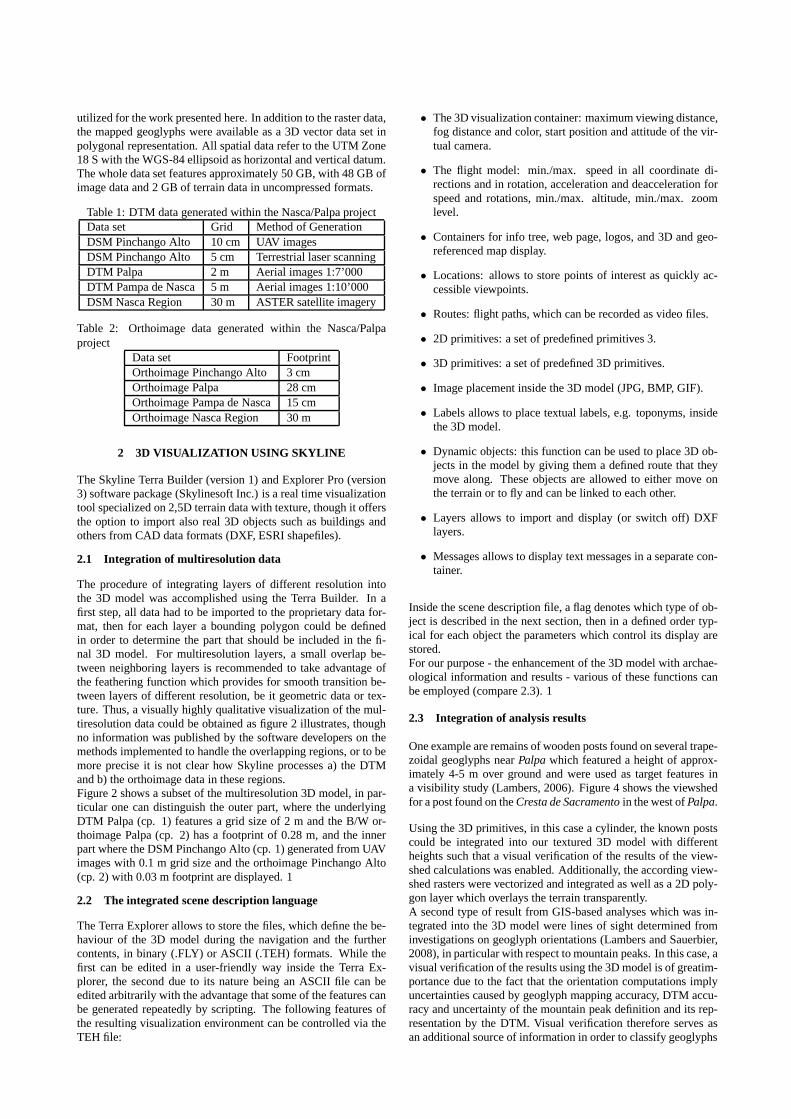
sight nearPalpa which were identified to point in direction to-wards a mountain peak and were imported to the 3D model forvisual inspection (figure 6). 1
3 CONCLUSIONS
The presented enhancement of textured 3D models by archaeo-logical features directs the usage of virtual reality apartfrom merepresentation towards being a tool for analytical work. Especiallyvisibility studies can be easily conducted without requiring ex-pert knowledge in GIS software but exploiting the functionalitypresent 3D terrain visualization software offers in a much moreuser-friendly though interactive mode.The here applied Skyline software serves as a suitable example,however similar software exists, both commercially and freelyavailable or in the open source domain, for the purpose of enhanc-ing reality-based textured 3D models by analysis results. GoogleEarthTM , Microsoft Virtual EarthTM or NASA WorldWindTM areother examples of real time 3D viewers which allow to a certainextent the import of data by the users. Expert knowledge is re-quired mostly only for the production of the 3D model in termsofdata acquisition and processing while the enhancement of the vir-tual scene with archaeological features can usually be handled byan untrained person. A feature that is still missing in these3D vi-sualization software packages is the capability to access externaldatabases online, e.g. by clicking on spatial objects in theviewerand formulating a query on these objects. Such functionality sofar mostly was implemented in research prototypes (Forte etal.,2001, Henze et al., 2005).
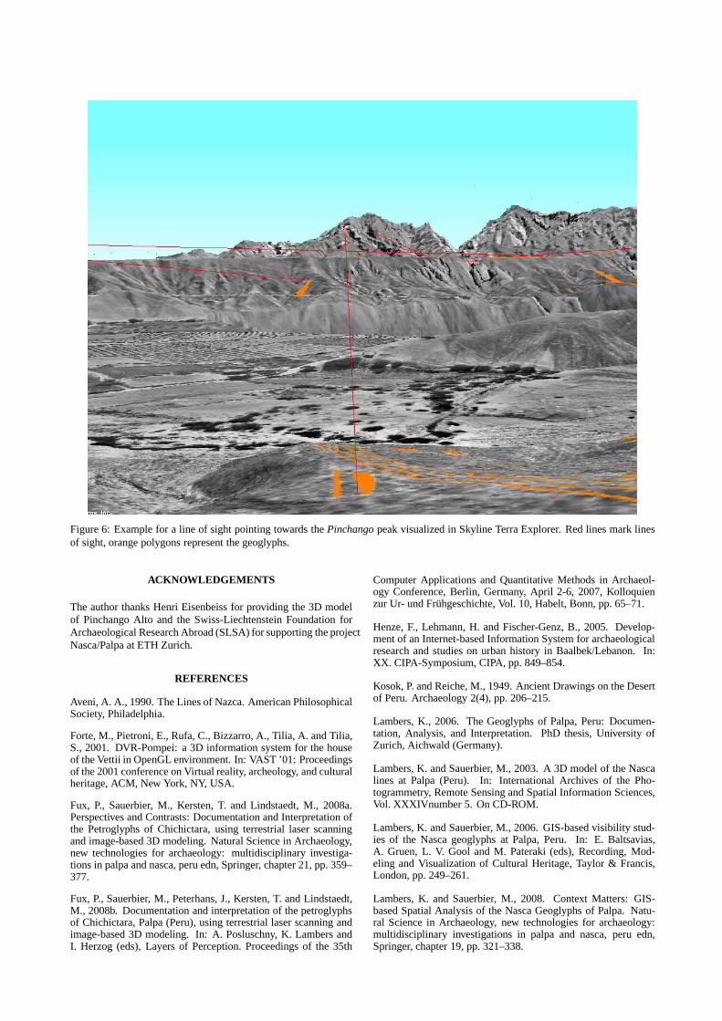
Figure 6: Example for a line of sight pointing towards thePinchango peak visualized in Skyline Terra Explorer. Red lines mark linesof sight, orange polygons represent the geoglyphs.
ACKNOWLEDGEMENTS
The author thanks Henri Eisenbeiss for providing the 3D modelof Pinchango Alto and the Swiss-Liechtenstein Foundation forArchaeological Research Abroad (SLSA) for supporting the projectNasca/Palpa at ETH Zurich.
REFERENCES
Aveni, A. A., 1990. The Lines of Nazca. American PhilosophicalSociety, Philadelphia.
Forte, M., Pietroni, E., Rufa, C., Bizzarro, A., Tilia, A. and Tilia,S., 2001. DVR-Pompei: a 3D information system for the houseof the Vettii in OpenGL environment. In: VAST ’01: Proceedingsof the 2001 conference on Virtual reality, archeology, and culturalheritage, ACM, New York, NY, USA.
Fux, P., Sauerbier, M., Kersten, T. and Lindstaedt, M., 2008a.Perspectives and Contrasts: Documentation and Interpretation ofthe Petroglyphs of Chichictara, using terrestrial laser scanningand image-based 3D modeling. Natural Science in Archaeology,new technologies for archaeology: multidisciplinary investiga-tions in palpa and nasca, peru edn, Springer, chapter 21, pp.359–377.
Fux, P., Sauerbier, M., Peterhans, J., Kersten, T. and Lindstaedt,M., 2008b. Documentation and interpretation of the petroglyphsof Chichictara, Palpa (Peru), using terrestrial laser scanning andimage-based 3D modeling. In: A. Posluschny, K. Lambers andI. Herzog (eds), Layers of Perception. Proceedings of the 35th
Computer Applications and Quantitative Methods in Archaeol-ogy Conference, Berlin, Germany, April 2-6, 2007, Kolloquienzur Ur- und Fruhgeschichte, Vol. 10, Habelt, Bonn, pp. 65–71.
Henze, F., Lehmann, H. and Fischer-Genz, B., 2005. Develop-ment of an Internet-based Information System for archaeologicalresearch and studies on urban history in Baalbek/Lebanon. In:XX. CIPA-Symposium, CIPA, pp. 849–854.
Kosok, P. and Reiche, M., 1949. Ancient Drawings on the Desertof Peru. Archaeology 2(4), pp. 206–215.
Lambers, K., 2006. The Geoglyphs of Palpa, Peru: Documen-tation, Analysis, and Interpretation. PhD thesis, University ofZurich, Aichwald (Germany).
Lambers, K. and Sauerbier, M., 2003. A 3D model of the Nascalines at Palpa (Peru). In: International Archives of the Pho-togrammetry, Remote Sensing and Spatial Information Sciences,Vol. XXXIVnumber 5. On CD-ROM.
Lambers, K. and Sauerbier, M., 2006. GIS-based visibility stud-ies of the Nasca geoglyphs at Palpa, Peru. In: E. Baltsavias,A. Gruen, L. V. Gool and M. Pateraki (eds), Recording, Mod-eling and Visualization of Cultural Heritage, Taylor & Francis,London, pp. 249–261.
Lambers, K. and Sauerbier, M., 2008. Context Matters: GIS-based Spatial Analysis of the Nasca Geoglyphs of Palpa. Natu-ral Science in Archaeology, new technologies for archaeology:multidisciplinary investigations in palpa and nasca, peruedn,Springer, chapter 19, pp. 321–338.
Figure 5: Lines of sight from geoglyphs towards mountain peaks.
Lambers, K., Eisenbeiss, H., Sauerbier, M., Kupferschmidt, D.,Gaisecker, T., Sotoodeh, S. and Hanusch, T., 2007. Combiningphotogrammetry and laser scanning for the recording and mod-elling of the Late Intermediate Period site of Pinchango Alto,Palpa, Peru. Journal of Archaeological Science 34, pp. 1702–1712.
Pavelka, K., 2007. Rectification of Petroglyphs with photogram-metrical methods. Dresdner Kartographische Schriften 25(12),pp. 103–114.
Reindel, M., 2007. The Geoglyphs of Palpa. An ArchaeologicalApproach. In: B. Teichert and C. Rust (eds), Symposium 2006 imZentrum fur interdisziplinare Forschungen der Universitat Biele-feld (ZIF), pp. 55–69.
Reindel, M., Cuadrado, J. I. and Lambers, K., 2001. Ab-schliessende Untersuchungen zu Geoglyphen und Siedlun-gen in Palpa, Sudperu: Ergebnisse der Feldkampagne 2000des Archaologischen Projektes Nasca-Palpa. Jahresbericht,Schweizerisch-Liechtensteinische Stiftung fr archaologischeForschungen im Ausland.
Sauerbier, M., 2008. Virtual Flight over the Nasca lines - auto-mated generation of a photorealistically textured 3D modelof thePampa de Nasca. Natural Science in Archaeology, new technolo-gies for archaeology: multidisciplinary investigations in palpaand nasca, peru edn, Springer Berlin, chapter 18, pp. 307–320.
Sauerbier, M., Fux, P. and Eisenbeiss, H., 2008. GIS-based ar-chaeological analysis of large areas in the Peruvian Andes basedon high resolution satellite imagery. In: R. Lasaponara andN. Masini (eds), Remote Sensing for Archaeology and CulturalHeritage Management, Rome, pp. 297–300.
Sauerbier, M., Schrotter, G., Lambers, K. and Eisenbeiss, H.,2006. Multi-Resolution Image-based Visualization of Archaeo-logical Landscapes in Palpa, Peru. In: S. Campana and M. Forte(eds), From Space To Place - 2nd International Conference onRemote Sensing in Archaeology, Proc. of the 2nd Int. Workshop,BAR International Series 1568, Archaeopress, Oxford, pp. 353–359.
Silverman, H., 1993. Cahuachi in the Ancient Nasca World. Uni-versity of Iowa Press, Iowa City.
Sossna, V., 2007. Siedlungsentwicklung und Siedlungsorganisa-tion der Nasca-Zeit im Raum Palpa, Sud-Peru. Master’s thesis,Freie Universitat Berlin, Berlin.