3d printing for urban planning: a physical enhancement … · realistic models, for example of city...
TRANSCRIPT
1 BACKGROUND
On a global scale, spatial applications have now become common in development planning. Spatial data handling in GIS world is prepared now to handle various formats of three dimensional perspective of physical environment. 3D Models are more commonly used now for various planning sectors such as city / urban planning, natural resource management, transportation planning etc (Stoter et al 2011, Zlatanova et al 2010). 3D visualization on a computer screen enhances the human understanding of the spatial aspects of a physical environment where many thematic concerns interact.
A 3D Model in GIS is thus depiction of our spatial data using its z properties to create a three dimensional environment which can be zoomed, rotated and viewed from different angles. With increasing focus of GIS industry, 3D modelling is gaining rapid steps towards creating more realistic models, for example of city landscapes with buildings, street furniture, topographic var-iations. Currently the focus is on enhancing the visualization process through introduction of texture creativity, shading, building facade presentation, fly-thru capabilities, rotation and zooming properties etc. However, the future 3D modelling for GIS data will have to address more analytical processes of true 3D model creations and thus 3D topology. This is important to meet the growing requirement of volumetric calculations for complex constructions and subsurface activities.
3D models are ideal for: Internal Communication, Education, Visualization of virtual solutions, Mission planning for homeland security, Terrain visualization and analysis, Battlefield simulation, Watershed visualization and analysis, Oil and gas field visualization, Base realignment and closure, Hydrologic visualization (Spatialresources, 2012). The terrain model can be used as an effective communication medium among stakeholders for conservation management (Rapidtoday, 2012). In case of disaster emergency which is a dynamic situation
3D printing for urban planning: A physical enhancement of spatial perspective
T. Ghawana Integrated Spatial Analytics Consultants, India
S. Zlatanova Delft University of Technology, GIS Technology Section, Delft, Netherlands
ABSTRACT: 3D models help in 3D visualization on computer screen which enhances the human understanding of the spatial aspects of a physical environment where many thematic concerns interact. But most of the 3D visualizations are on 2D screen, which has its limitations. 3D printing is the potential next step in this direction to enhance the physical enhancement of spatial perspective. GIS applications for various sectors produce a lot of thematic data which can be 3D printed so that to expedite the process of discussions or negotiations and enhance the mutual understanding among the different stakeholders. This paper investigates the size and the resolution or city model that can be printed as 3D physical models. Considering a sample example from a sub-city Dwarka in Delhi, India, we have tried to show the practical considerations for a small scale city buildings 3D printing on a detailed level as per CityGML specifications.
(changing floodwater levels, hospital statuses, and hot spots), to identify the neediest areas and to provide quick relief, continuous re-mapping of the terrain, including buildings, water and other natural features, is much required (Zcorp, 2012). Full coloured outputs are possible with 3D printers. They are also helpful in geological research and subsurface visualization (Paraschou et al., 2011). The paper discusses the next possible step to create more realistic experience of 3D presentation of spatial data for the GIS community. 3D physical models have been largely used in many occasions in urban planning for presenting new developments. However, the construction of such models is time consuming and very expensive. 3D printing is a relatively unexplored concept which we aim to analyze. We ultimately aim to describe how it can contribute to enhance our experience of spatial factors in such applications. A sample case from a sub-city of Delhi, India is used to describe its practical feasibility. In this paper we take the first step. We establish a link between the levels of detail (LOD) of CityGML and printing capacities of current 3D printers. This paper is explicitly based on empirical derivations from the printing characteristics of 3D printers and CityGML model. There is no practical experiment done by creating any kind of physical models using 3D printers.
2 3D PRINTING
3D printing which is popularly known as “rapid prototyping” is defined in various terms. However a few definitions which highlight different aspects of 3D printing are: 3D Printing is a technique that deposits material layer by layer using a head similar to that of an inkjet printer. The head tends to move along the X and Y axes and the object being printed moves up and down on the Z axis. It is a process whereby the information in a digital file describing an ob-ject virtually (such as an STL or CAD file) is used to rapidly make a real object, usually by one single machine and usually in limited production runs (Shapeways, 2008).
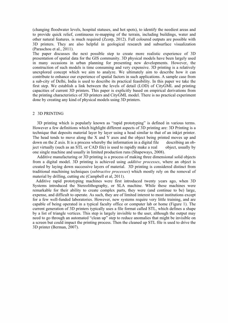
Additive manufacturing or 3D printing is a process of making three dimensional solid objects from a digital model. 3D printing is achieved using additive processes, where an object is created by laying down successive layers of material. 3D printing is considered distinct from traditional machining techniques (subtractive processes) which mostly rely on the removal of material by drilling, cutting etc (Campbell et al, 2011). Additive rapid prototyping machines were first introduced twenty years ago, when 3D Systems introduced the Stereolithography, or SLA machine. While these machines were remarkable for their ability to create complex parts, they were (and continue to be) large, expense, and difficult to operate. As such, they are of limited interest to most institutions except for a few well-funded laboratories. However, new systems require very little training, and are capable of being operated in a typical faculty office or computer lab or home (Figure 1). The current generation of 3D printers typically uses a file format called STL, which defines a shape by a list of triangle vertices. This step is largely invisible to the user, although the output may need to go through an automated “clean up” step to reduce anomalies that might be invisible on a screen but could impact the printing process. Then the cleaned up STL file is used to drive the 3D printer (Berman, 2007).
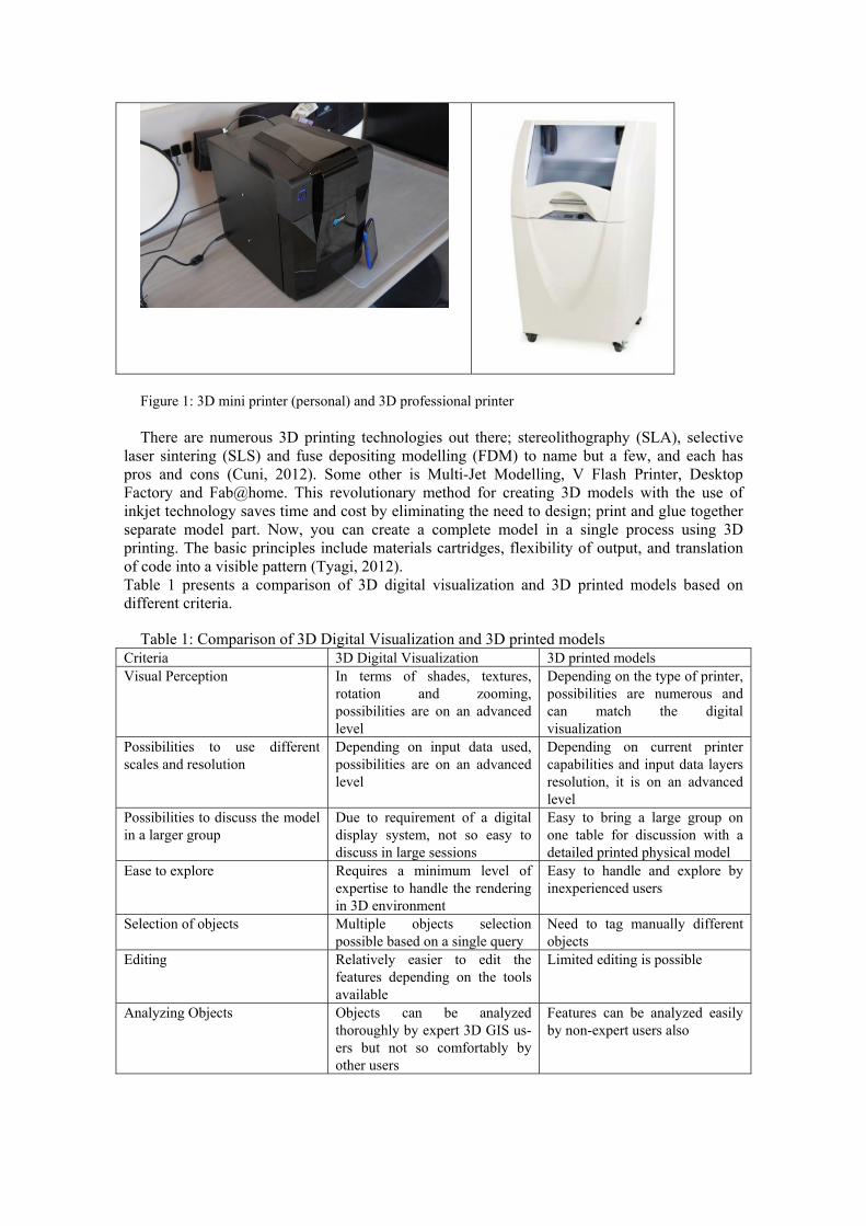
Figure 1: 3D mini printer (personal) and 3D professional printer There are numerous 3D printing technologies out there; stereolithography (SLA), selective
laser sintering (SLS) and fuse depositing modelling (FDM) to name but a few, and each has pros and cons (Cuni, 2012). Some other is Multi-Jet Modelling, V Flash Printer, Desktop Factory and Fab@home. This revolutionary method for creating 3D models with the use of inkjet technology saves time and cost by eliminating the need to design; print and glue together separate model part. Now, you can create a complete model in a single process using 3D printing. The basic principles include materials cartridges, flexibility of output, and translation of code into a visible pattern (Tyagi, 2012). Table 1 presents a comparison of 3D digital visualization and 3D printed models based on different criteria.
Table 1: Comparison of 3D Digital Visualization and 3D printed models Criteria 3D Digital Visualization 3D printed models Visual Perception In terms of shades, textures,
rotation and zooming, possibilities are on an advanced level
Depending on the type of printer, possibilities are numerous and can match the digital visualization
Possibilities to use different scales and resolution
Depending on input data used, possibilities are on an advanced level
Depending on current printer capabilities and input data layers resolution, it is on an advanced level
Possibilities to discuss the model in a larger group
Due to requirement of a digital display system, not so easy to discuss in large sessions
Easy to bring a large group on one table for discussion with a detailed printed physical model
Ease to explore Requires a minimum level of expertise to handle the rendering in 3D environment
Easy to handle and explore by inexperienced users
Selection of objects Multiple objects selection possible based on a single query
Need to tag manually different objects
Editing Relatively easier to edit the features depending on the tools available
Limited editing is possible
Analyzing Objects Objects can be analyzed thoroughly by expert 3D GIS us-ers but not so comfortably by other users
Features can be analyzed easily by non-expert users also
2D
Pap
er
/ O
ther
Mat
eria
l M
aps
(Col
our/
B &
W)
Col
our
/ B
& W
Sca
nned
2D
Im
ages
(n
on-i
nter
acti
ve)
GIS
2D
Dat
a (I
nter
acti
ve &
Att
rib-
utes
Att
ache
d)
GIS
3D
Dat
a (I
nter
acti
ve &
Att
rib-
utes
Att
ache
d, V
irtu
al M
odel
s)
Fly
-thr
u 3D
Sim
ulat
ion
Tou
rs,
rec-
orde
d as
mot
ion
vide
o
Han
dmad
e3D
M
odel
s of
3D
D
ata
(Phy
sica
l Mod
els)
Dig
ital
3D p
rint
ing
of 3
D D
ata
with
Z
pro
pert
ies
(Phy
sica
l Mod
els)
A 3D digital visualization displays the representations of real world objects in a virtual world quite successfully the way we perceive objects in a real world. On the other hand a 3D printed physical model can get us to understand that how an object will look like actually in real world in all dimensions. In fact, a 3D printed model could be the physical object itself depending on the object and 3D printing scale in all dimensions. The level of comfort and ease for exploring and analyzing the features presented by a large group which can be having several non-expert users, can be a comparative advantage over the 3D digital visualization. Also it eliminates the need to have a digital display system every time which could be a hindrance in some cases.
3 LINKING 3D PRINTING AND CITYMODELS
GIS applications are successfully implemented throughout the world in various sectors. Users of these applications vary from GIS experts to general communities coming from different strata of population. Therefore more appealing means for 3D representation are needed. Virtual scenes generated in 3D GIS environment enhance the understanding of users. 3D scenes are going to become more and more realistic. However 3D models are visualized on 2D screen, which reduces the immersion effect and may lead to misjudgment (e.g. the size of the buildings or the general appearance). 3D printing has the potential to bridge the gap between the virtual and physical world. Software is available now, which can handle the GIS data complexity for 3D printing (custom3d, 2012; Spatialresources, 2012). The visualization process has passed many stages towards realistic visualization. The figure 2 shows the development process of spatial data visualization enhancement. Earlier, only 2D maps (paper / other material) were available which could model the real world in a 2 dimensional way with a fixed scale in a non-interactive static form. With the advent of Information Technologies, it became possible to scan these maps and create digital non-interactive 2D images. These images can be zoomed in and out as per requirements and thus challenged the concept of scale in a virtual world. With the introduction of Geospatial technologies in a digital world, it became possible to create interactive 2D data with non-spatial attributes attached to each feature. With the advancement of GIS technology, it became possible to create 3D interactive data and virtual models with attributes attached. Rapid new changes in 3D modeling capabilities introduced the concepts of Fly-thru 3D simulations tours and their recording as motion video in the same application software. Handmade 3D models of 3D data bring a physical model in shape, of the environment we would like to visualize and work on. However this process is cumbersome and time consuming. With new hardware advancement, 3D printers are introduced in the market and thus made possible physi-cal model creation in a relatively less time consuming manner.
Figure 2: Development Process of Spatial Data Visualization Enhancement With a 3D printer, we can create objects impossible to make as a single piece by other means
of production. It is possible to print objects within objects, hollow parts, interconnected parts,
moving pieces, complex twists, and intricate details (Cuni, 2012). 3D Prototyping enables you to output high-quality terrain, urban and subsurface maps in hours at very low cost (3dprototype, 2012). Rapid prototype technologies are a natural fit for 3D topographic or terrain mapping, because of the models geometric complexity, and their lack of a need for any special structural integrity (Rapidtoday, 2012).
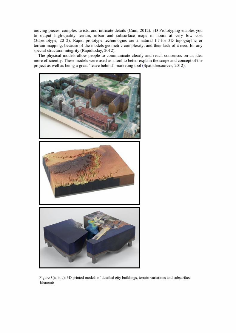
The physical models allow people to communicate clearly and reach consensus on an idea more efficiently. These models were used as a tool to better explain the scope and concept of the project as well as being a great "leave behind" marketing tool (Spatialresources, 2012).
Figure 3(a, b, c): 3D printed models of detailed city buildings, terrain variations and subsurface Elements
Examples of physical models City Models Urban models printed using 3D printers can create landscapes in urban environment which can include dense level of infrastructure at various scales and details. It could provide buildings modeled on a desired scale with minute details to visualize. This can help city / urban planners to discuss the issues from street level planning to zonal planning scale in one go (Figure 3a).
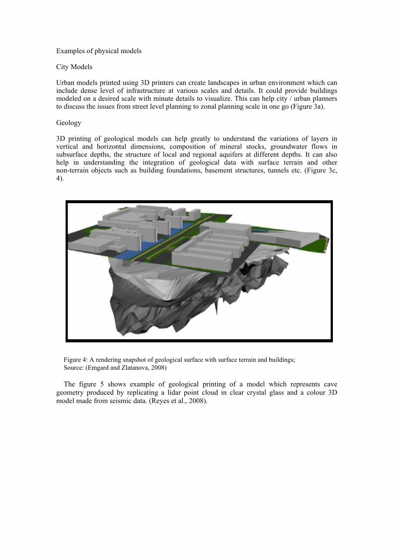
Geology 3D printing of geological models can help greatly to understand the variations of layers in vertical and horizontal dimensions, composition of mineral stocks, groundwater flows in subsurface depths, the structure of local and regional aquifers at different depths. It can also help in understanding the integration of geological data with surface terrain and other non-terrain objects such as building foundations, basement structures, tunnels etc. (Figure 3c, 4).
Figure 4: A rendering snapshot of geological surface with surface terrain and buildings; Source: (Emgard and Zlatanova, 2008) The figure 5 shows example of geological printing of a model which represents cave
geometry produced by replicating a lidar point cloud in clear crystal glass and a colour 3D model made from seismic data. (Reyes et al., 2008).

(a) 3D printed Cave Geometry in Clear Crystal Glass
(b) 3D printed Color 3D model made from seismic data.
Figure 5 a & b: Geological layers 3D printed physical models
Participatory planning Another significant contribution of 3D physical models can be seen in participatory GIS for conflict resolution. It is a common practice nowadays to create 3D physical models to engage various stakeholders (communities/user groups) into negotiation process for conflict resolution by defining boundary perceptions from each stakeholder’s perspective (Figure 6). Through a participatory process, Participatory 3D Modelling (P3DM) merges conventional spatial information (contours) with people's mental maps; makes information tangible and meaningful-to-all, and visualizes scaled and geocoded indigenous spatial knowledge (IAPAD, 2013). Landscape: These 3D physical models of landscape are generated manually or semi-manual methods. This takes considerable time and manual efforts. Sheets of cardboard are cut in the shape of the contour lines and pasted on top of each other to create a three-dimensional representation of topography (Figure 6). Geographic features can be identified on the model using pushpins (for points), coloured string (for lines) and paint (for areas). Data depicted on the model can be extracted, digitized and incorporated into a GIS (IFAD, 2009). With 3D printing, it takes a much shorter time and thus could help to speed up the process of negotiations for conflict resolution.
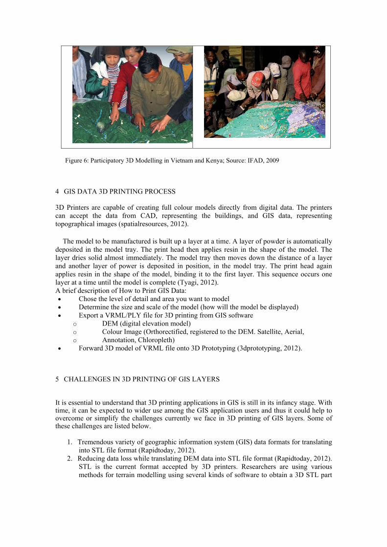
Figure 6: Participatory 3D Modelling in Vietnam and Kenya; Source: IFAD, 2009
4 GIS DATA 3D PRINTING PROCESS
3D Printers are capable of creating full colour models directly from digital data. The printers can accept the data from CAD, representing the buildings, and GIS data, representing topographical images (spatialresources, 2012).
The model to be manufactured is built up a layer at a time. A layer of powder is automatically
deposited in the model tray. The print head then applies resin in the shape of the model. The layer dries solid almost immediately. The model tray then moves down the distance of a layer and another layer of power is deposited in position, in the model tray. The print head again applies resin in the shape of the model, binding it to the first layer. This sequence occurs one layer at a time until the model is complete (Tyagi, 2012). A brief description of How to Print GIS Data: Chose the level of detail and area you want to model Determine the size and scale of the model (how will the model be displayed) Export a VRML/PLY file for 3D printing from GIS software
o DEM (digital elevation model) o Colour Image (Orthorectified, registered to the DEM. Satellite, Aerial, o Annotation, Chloropleth)
Forward 3D model of VRML file onto 3D Prototyping (3dprototyping, 2012). 5 CHALLENGES IN 3D PRINTING OF GIS LAYERS
It is essential to understand that 3D printing applications in GIS is still in its infancy stage. With time, it can be expected to wider use among the GIS application users and thus it could help to overcome or simplify the challenges currently we face in 3D printing of GIS layers. Some of these challenges are listed below.
1. Tremendous variety of geographic information system (GIS) data formats for translating
into STL file format (Rapidtoday, 2012). 2. Reducing data loss while translating DEM data into STL file format (Rapidtoday, 2012).
STL is the current format accepted by 3D printers. Researchers are using various methods for terrain modelling using several kinds of software to obtain a 3D STL part
in several steps. There is a way developed by some researchers to convert DEM ASCII XYZ data directly to a 3D STL part (Modi et al., 2012).
3. 3D printing is not necessarily a cheap process, therefore it should be always taken into consideration as the quantity of the material used for physical model (Cuni, 2012).
4. The resolution and accuracy of a 3D print can be very high, but at the same time, small details can be lost. The width of the material it deposits will determine the size of the smallest details that you can print. Also, this puts a lower limit on the thickness of walls in your print (Ultimaker, 2012).
5. Work with valid 3D digital models. This means that the user should prepare the model in advance. For example she/he should add faces until the model is a close volume. This is called “water tightness” rule. Another important aspect is that you should not be able to peek inside your model (Ultimaker, 2012).
6. GIS data varies on compression and has different projections. It is usually processed to work well on a flat map, so it needs to be put back in its original shape (Rapidtoday, 2012).
6 3D PRINTING AND CITYGML
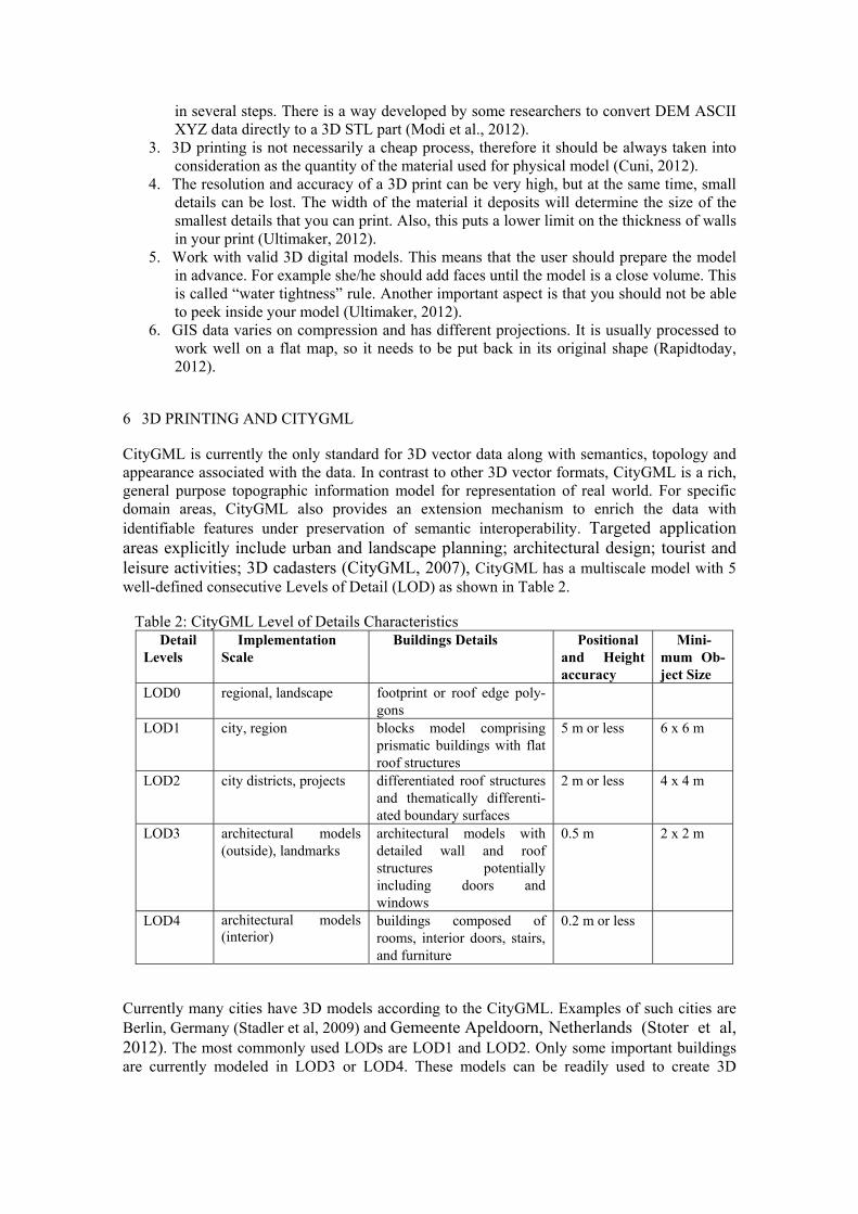
CityGML is currently the only standard for 3D vector data along with semantics, topology and appearance associated with the data. In contrast to other 3D vector formats, CityGML is a rich, general purpose topographic information model for representation of real world. For specific domain areas, CityGML also provides an extension mechanism to enrich the data with identifiable features under preservation of semantic interoperability. Targeted application areas explicitly include urban and landscape planning; architectural design; tourist and leisure activities; 3D cadasters (CityGML, 2007), CityGML has a multiscale model with 5 well-defined consecutive Levels of Detail (LOD) as shown in Table 2. Table 2: CityGML Level of Details Characteristics
Detail Levels
Implementation Scale
Buildings Details Positional and Height accuracy
Mini-mum Ob-ject Size
LOD0 regional, landscape footprint or roof edge poly-gons
LOD1 city, region blocks model comprising prismatic buildings with flat roof structures
5 m or less 6 x 6 m
LOD2 city districts, projects differentiated roof structures and thematically differenti-ated boundary surfaces
2 m or less 4 x 4 m
LOD3 architectural models (outside), landmarks
architectural models with detailed wall and roof structures potentially including doors and windows
0.5 m 2 x 2 m
LOD4 architectural models (interior)
buildings composed of rooms, interior doors, stairs, and furniture
0.2 m or less
Currently many cities have 3D models according to the CityGML. Examples of such cities are Berlin, Germany (Stadler et al, 2009) and Gemeente Apeldoorn, Netherlands (Stoter et al, 2012). The most commonly used LODs are LOD1 and LOD2. Only some important buildings are currently modeled in LOD3 or LOD4. These models can be readily used to create 3D
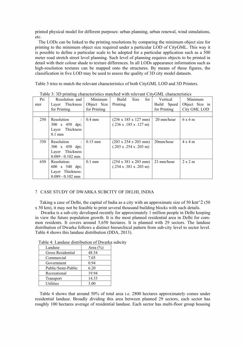
printed physical model for different purposes: urban planning, urban renewal, wind simulations, etc. The LODs can be linked to the printing resolutions by comparing the minimum object size for printing to the minimum object size required under a particular LOD of CityGML. This way it is possible to define a particular scale to be adopted for a particular application such as a 500 meter road stretch street level planning. Such level of planning requires objects to be printed in detail with their colour shade to texture differences. In all LODs appearance information such as high-resolution textures can be mapped onto the structures. By means of these figures, the classification in five LOD may be used to assess the quality of 3D city model datasets.
Table 3 tries to match the relevant characteristics of both CityGML LOD and 3D Printers.
Table 3: 3D printing characteristics matched with relevant CityGML characteristics Pri
nter Resolution and
Layer Thickness for Printing
Minimum Object Size for Printing
Build Size for Printing
Vertical Build Speed for Printing
Minimum Object Size in City GML LOD
250 Resolution :
300 x 450 dpi; Layer Thickness 0.1 mm
0.4 mm
(236 x 185 x 127 mm) (.236 x .185 x .127 m)
20 mm/hour 6 x 6 m
350 Resolution : 300 x 450 dpi; Layer Thickness 0.089 - 0.102 mm
0.15 mm (203 x 254 x 203 mm) (.203 x .254 x .203 m)
20mm/hour 4 x 4 m
650 Resolution: 600 x 540 dpi; Layer Thickness: 0.089 - 0.102 mm
0.1 mm
(254 x 381 x 203 mm) (.254 x .381 x .203 m)
23 mm/hour
2 x 2 m
7 CASE STUDY OF DWARKA SUBCITY OF DELHI, INDIA
Taking a case of Delhi, the capital of India as a city with an approximate size of 50 km^2 (50 x 50 km), it may not be feasible to print several thousand building blocks with such details. Dwarka is a sub-city developed recently for approximately 1 million people in Delhi keeping in view the future population growth. It is the most planned residential area in Delhi for com-mon residents. It covers around 5,650 hectares. It is planned with 29 sectors. The landuse distribution of Dwarka follows a distinct hierarchical pattern from sub-city level to sector level. Table 4 shows this landuse distribution (DDA, 2013). Table 4: Landuse distribution of Dwarka subcity
Landuse Area (%) Gross Residential 48.54 Commercial 7.05 Government 0.94 Public/Semi-Public 6.20 Recreational 19.94 Transport 14.33 Utilities 3.00
Table 4 shows that around 50% of total area i.e. 2800 hectares approximately comes under
residential landuse. Broadly dividing this area between planned 29 sectors, each sector has roughly 100 hectares average of residential landuse. Each sector has multi-floor group housing

society buildings lined up both sides of internal roads. These society boundaries are clearly demarcated using cemented boundary walls for each society premises.
Figure 7: Layout Plan of Sector 6, Dwarka, Delhi Figure 7shows one such sample of sector 6 with total area of 93 hectares. Residential landuse
allocated is approximately 41 hectares. These 41 hectares can be converted to 410,000 in square meters.
Using Google Earth we have snapped satellite images of sector 6 in year 2011 (Figure 8). This shows the multi-floor residential apartments with clear cut boundaries of cemented walls.

Figure 8: Satellite Image of Sector 6 in 2011; Source: Google Earth LOD3 detail printing can be commercially feasible for a small scale of land development
with buildings. The printing of detailed buildings facades completed with doors, balconies and windows is possible in terms of printing time and maximum buildings blocks in terms of number of parts to complete a building printout.
Taking a part of Sector 6, Dwarka, we have marked the boundaries of some of the residential apartment’s society premises on both sides of a road in Figure 9. Using GIS software, we have measured the covering areas of societies with the following ranges:
Maximum: 170 m x 125 m x 40 m Minimum: 80 m x 80 m x 40 m. Usually group housing societies divide the buildings in alphabetic blocks which are mostly disconnected with each other or connected through only a viaduct. On an average, the dimensions of these blocks are around 30 meter x 30 meter in X, Y terms. In z terms, average height is 40 meters.
Table 5: Single Block Printing Size and Scaling Requirements Single piece maximum print‐ing object size
Actual Object Size Scale Required
250 mm x 380 mm x 200 mm 30 m x 30 m (X,Y) x 40 m (Z)
1:120 x 1:78 (X,Y) x 1:200 (Z)
With an average scale of 1:160 for the building block, a window size of 2 x 2 meter
(200 cm/2000 mm) can be printed in approximately 12 mm. Usually a society has three to four such building blocks, which means that these can be 3D
printed in manageable units. With a vertical speed of 0.9 inch/hour (23 mm/hour), a window of 2 meter x 2 meter can be printed with above mentioned scale approximately in a few minutes considering it as a part of 30 x 30 meter building block.
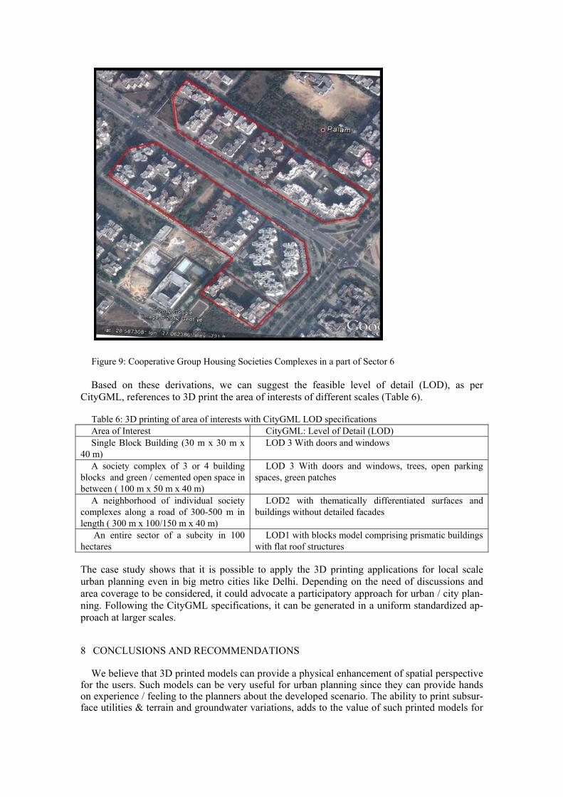
Figure 9: Cooperative Group Housing Societies Complexes in a part of Sector 6 Based on these derivations, we can suggest the feasible level of detail (LOD), as per
CityGML, references to 3D print the area of interests of different scales (Table 6). Table 6: 3D printing of area of interests with CityGML LOD specifications Area of Interest CityGML: Level of Detail (LOD) Single Block Building (30 m x 30 m x
40 m) LOD 3 With doors and windows
A society complex of 3 or 4 building blocks and green / cemented open space in between ( 100 m x 50 m x 40 m)
LOD 3 With doors and windows, trees, open parking spaces, green patches
A neighborhood of individual society complexes along a road of 300-500 m in length ( 300 m x 100/150 m x 40 m)
LOD2 with thematically differentiated surfaces and buildings without detailed facades
An entire sector of a subcity in 100 hectares
LOD1 with blocks model comprising prismatic buildings with flat roof structures
The case study shows that it is possible to apply the 3D printing applications for local scale urban planning even in big metro cities like Delhi. Depending on the need of discussions and area coverage to be considered, it could advocate a participatory approach for urban / city plan-ning. Following the CityGML specifications, it can be generated in a uniform standardized ap-proach at larger scales.
8 CONCLUSIONS AND RECOMMENDATIONS
We believe that 3D printed models can provide a physical enhancement of spatial perspective for the users. Such models can be very useful for urban planning since they can provide hands on experience / feeling to the planners about the developed scenario. The ability to print subsur-face utilities & terrain and groundwater variations, adds to the value of such printed models for

the planners. This 3D ability allows them to plan properly for various types of landuse including utilities in the dense urban areas. Currently such 3D printed models dedicated material require-ments for printing ink. Models printing can take a few minutes to few days depending on the level of details and scale of application. But the models can stay for years.
3D printed models can be used for wide scale applications related to urban planning, to pro-vide more realistic interfaces for negotiations between stakeholders and presenting new devel-opments to citizens. Street level planning where community participation can play a major role on the local scale, is such an area where detailed 3D printed models of landscape, buildings, road furniture and other infrastructure can be printed on a detailed level.
3D printed models can be used in Delhi by various agencies. Delhi Development authority
(DDA, 2013) is the nodal agency to make development plans for Delhi while municipalities have a role of maintaining the developed areas (MCD Online, 2013). DDA and Municipalities each have their own zonal boundaries and have their own zonal and other level plans. With a rapidly developing delhi in terms of population and denser residential settlements, it is becom-ing imperative that these agencies need to integrate their efforts together so that to have more participatory approach for land development and its maintenance. To adopt such participatory approach on a wide scale, 3D printed models of the area under consideration can bring together many stakeholders on a table and thus expedite the process of negotiations and thus planning.
References: 3dprototype; Civil Engineering
Website: www.3dprototype.com.au/Civil-Engineering.html; Accessed in August 2012 Berman, A. M., 2007; 3D Printing: Making the Virtual Real; EDUCAUSE Evolving Technologies
Committee, Art Center College of Design Campbell T., Williams C., Ivanova O. and Garrett B., 2011, Strategic Foresight Report; Could 3D printing Change the World?: Technologies, Potential and Implications of Additive Manufacturing
CityGML, 2007; Candidate OpenGIS CityGML Implementation Specification (City Geography Markup Language)
Cuni, B., Learn how to create a watertight 3D prototype model for 3D printing, and use your skills to
enter to win a MakerBot Thing-O-Matic worth $2,500 Website: http://www.3dartistonline.com/news/2011/12/how-to-make-a-model-for-3d-printing/; Accessed in August 2012.
Custom3d; Architecture (Models and GIS)
Website: http://www.custom3d.co.za/index.php?option=com_content&view=article&id=70&Itemid=24; Accessed in August 2012.
DDA, 2013; Urban Extension Projects - Dwarka, Delhi Development Authority,
Website: http://dda.org.in/planning/dwarka.htm; accessed in January 2013
Emgård, K.L. and S. Zlatanova, 2008, Design of an integrated 3D information model. In Coors, Rumor, Fendel&Zlatanova (Eds,), Urban and regional data management: UDMS annual 2007 (pp. 143-156), Taylor & Francis Group, London, UK
IAPAD; About Participatory 3D Modelling;
Website: http://www.iapad.org/p3dm.htm; Accessed in February 2013 IFAD, 2009; Good Practices in Participatory Mapping, A review prepared for International Fund for
Agricultural Development

MCD Online, 2013; Municipal Corporation of Delhi Website: http://www.mcdonline.gov.in/; accessed in January 2013
Modi, Y., Beer, D. J. de and Agarwal, S.; 2012; Physical Modelling of Terrain Directly from Surfer Grid and Arc/Info ASCII Data Formats; South African Journal of Industrial Engineering, July 2012, Vol 23 (2): pp 23-241
Website: http://sajie.journals.ac.za Paraschou, C. (Babis) and Boehlein M., 2011; Using Oblique & 3D Imaging for Map Production &
GIIS Support in Bosnia – Herzegovina, Defence Geointelligence 2011, EUFOR RAPIDTODAY; GIS 3D PRINTING MADE EASIER WITH SOFTWARE
Website: http://www.rapidtoday.com/GIS-3D-Printing.html; Accessed in August 2012 Reyes, R., Bellian, J. A., Dunlap, D. B., and Eustice, R. A., 2008; Cyber Techniques used to Produce Physical Geological Models; 2008 Joint Meeting of The Geological Society of America, Soil Science Society of America, American Society of Agronomy, Crop Science Society of America, Gulf Coast Association of Geological Societies with the Gulf Coast Section of SEPM
Website: https://webspace.utexas.edu/reyesr/publications/gsa2008.html Shapeways, 2008; 3D Printing. A Definition and Links
Website: http://www.shapeways.com/blog/archives/39-3D-Printing.-A-definition-and-links.html; Accessed in August 2012
Spatialresources; 3D Physical Models from GIS and Engineering Data
Website: http://www.spatialresources.com/id28.html; Accessed in August 2012 Stadler, A., Nagel, C., König, G., Kolbe, T. H., 2009; Making interoperability persistent: A 3D ge-odatabase based on CityGML; Proceedings of the 3rd International Workshop on 3D Geo-Information, Seoul, Korea. Lecture Notes in Geoinformation & Cartography, Springer Verlag, 2009
Stoter, J., Brink, L. v/d, Vosselman, G., Goos, J., Zlatanova, S., Verbree E., Klooster, R., Berlo, L. van, Vestjens, G., Reuvers, M. and Thorn, S., 2011, A generic approach for 3D SDI in the Netherlands, In: Proceedings of the Joint ISPRS Workshop on 3D City Modelling&Applications and the 6th 3D GeoInfo Conference, 26-28 June, 2011, Wuhan, China Stoter J., Goos J., Trakas A., 2012; CityGML and The Netherlands Open 3D Modelling Standard: Building the open 3D Information Infrastructrure for a Flat Land, September 20th, 2012 Website:http://www.directionsmag.com/articles/building-the-open-3d-information-infrastructure-for-a-flat-land-ogc/276211; Accessed in February 2013. Tyagi G., 3D Printing Technology
Website: nicsu.up.nic.in/knowdesk/3D-Printing-Technology.pdf; Accessed in August 2012
Ultimaker; Using SketchUp for 3D Printing Website: http://wiki.ultimaker.com/Using SketchUp for 3D printing; Accessed in August 2012
Zcorp; U.S. Military Better Visualizes Unfamiliar Settings With 3D Printing;
Website:http://www.zcorp.com/en/Solutions/Geospatial/U.S.-Military-Better-Visualizes/spage.aspx; Accessed in August 2012 Zlatanova, S., Itard, L., Kibria, M. S. and Dorst, M. van, 2010, A user requirements study of digital 3D
models for urban renewal, In: Open House International, Volume 35, 3, pp. 37-46