3d modeling of temperature distribution for absorber tube ... · pdf fileconcentrator, power...
TRANSCRIPT
International Journal of Engineering and Applied Sciences (IJEAS)
ISSN: 2394-3661, Volume-2, Issue-6, June 2015
99 www.ijeas.org
Abstract— Solar Parabolic Trough Collectors (PTCs) are
currently used for the production of electricity and applications
with relatively higher temperature. In this work, temperature
distribution of absorber tube for fluid flow in a parabolic trough
collector is studied. Three dimensional temperature distribution
of the absorber tube due to uniform heat flux is analyzed by
numerically. This heat flux is determined based on 21st
December of Mandalay which has the tropical climate in Upper
Myanmar. Soltrace software is used to check the theoretical
results of heat flux. Three types of fluid are used as heat transfer
fluid and simulations are carried out k-ε model using
Computational Fluid Dynamics CFD, COMSOL Multiphysics®
4.3b, for constant flow rate of fluid. It is observed that fluid is
higher in temperature at the exit end of absorber tube with fluid
flow rate of 0.5 m/s and solar flux condition of 938 W/m2.
Index Terms— parabolic trough collector, heat transfer fluid,
absorber tube, heat flux, temperature distribution
I. INTRODUCTION
In the present, solar technology for electricity generation can
be made by various systems such as parabolic trough,
parabolic dish, and Fresnel lens [21] mon m p ol
o oll o mo n ll pl n o n
o l P ol o oll o n op
mp p o on n n ol oll o
operate by using reflectors to concentrate sunlight on the
absorber of a solar collector, the size of the absorber can be
dramatically reduced, which reduces heat losses and increases
efficiency at high temperatures. A parabolic trough collector
system as illustrated in Fig. 1 is composed of a sheet of
reflective material, usually silvered acrylic, which is bent into
a parabolic shape. The long parabolic shaped modules have a
linear focus (focal line) along which an absorber is mounted.
A trough-shape parabolic trough mirror concentrates sunlight
on the absorber tube which is placed at the focal point. The
parabolic trough collector therefore suits for medium
temperature conversion of solar radiation. The temperature
rise depends on the geometrical concentration ratio and
optical properties of the collector as well as fluid flow in the
tube. Such studies are needed to find three-dimensional
temperature distribution of the absorber tube. In this article,
three dimensional temperature distribution of the absorber
tube of LS-2 collector are determined numerically for various
heat transfer fluid.
A parabolic trough collector includes the receiver tube, the
Mya Mya Mon, Department of Mechanical Engineering, Mandalay
Technological University, Mandalay, Myanmar, +95933538170.
Myat Myat Soe, Department of Mechanical Engineering, Mandalay
Technological University, Mandalay, Myanmar, +95943014802.
Maw Maw Htay Department of Mechanical Engineering, Mandalay
Technological University, Mandalay, Myanmar, +959400503768.
concentrator, power transmition, collector structure. The
receiver is the element of the system where solar radiation is
absorbed and converted to thermal energy. It includes an
absorber tube and its associated glass cover [1]. The receiver
is a key component of the parabolic trough solar plant. It plays
an important role in the energy conversion of concentrated
sunlight into fluid thermal energy through an absorber tube.
The working fluid in the receiver tube absorbs solar energy
and transfers it to water in heat exchangers to produce hot
water steam. The receiver is covered by a glass tube to reduce
thermal radiation as well as convection heat loss to the free air
which moves round the receiver. To reduce further the heat
losses from the absorber, air is evacuated from the space
between absorber and glass cover.
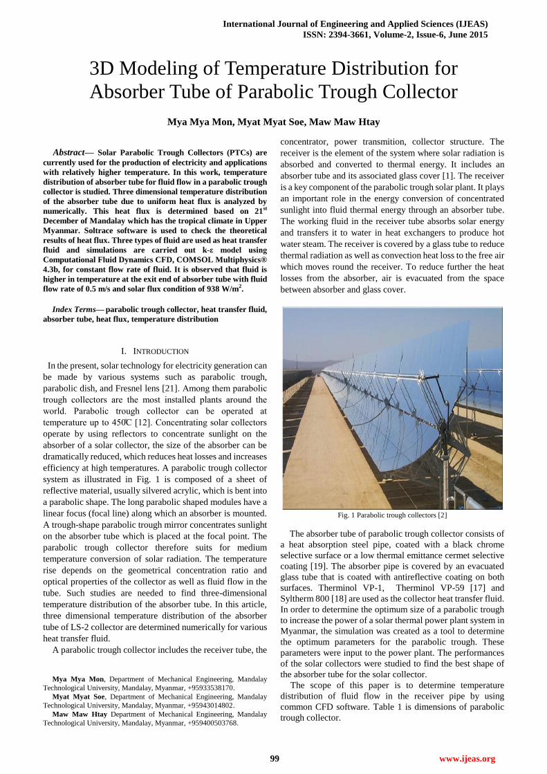
Fig. 1 Parabolic trough collectors [2]
The absorber tube of parabolic trough collector consists of
a heat absorption steel pipe, coated with a black chrome
selective surface or a low thermal emittance cermet selective
coating [19]. The absorber pipe is covered by an evacuated
glass tube that is coated with antireflective coating on both
surfaces. Therminol VP-1, Therminol VP-59 [17] and
Syltherm 800 [18] are used as the collector heat transfer fluid.
In order to determine the optimum size of a parabolic trough
to increase the power of a solar thermal power plant system in
Myanmar, the simulation was created as a tool to determine
the optimum parameters for the parabolic trough. These
parameters were input to the power plant. The performances
of the solar collectors were studied to find the best shape of
the absorber tube for the solar collector.
The scope of this paper is to determine temperature
distribution of fluid flow in the receiver pipe by using
common CFD software. Table 1 is dimensions of parabolic
trough collector.
3D Modeling of Temperature Distribution for
Absorber Tube of Parabolic Trough Collector
Mya Mya Mon, Myat Myat Soe, Maw Maw Htay

3D Modeling of Temperature Distribution for Absorber Tube of Parabolic Trough Collector
100 www.ijeas.org
Fig. 2. Components of an absorber tube of parabolic trough collector [1]
TABLE I
DIMENSIONS OF PARABOLIC TROUGH COLLECTOR [5]
Width of collector (W) 5 m
Length of collector (L) 7.8 m
Outer diameter of absorber tube (Do) 0.07 m
Inner diameter of absorber tube (Di) 0.066 m
Reflectivity of receiver 0.85
II. MATERIALS AND METHOD
The heat flux of parabolic trough collector is analysed by
theoretically and numerically to use as input data in three
dimensional temperatures distribution of absorber tube of
parabolic trough collector. The heat fluxes are considered for
tropical climate of Mandalay in Myanmar. The heat flux
results are calculated based on 21st December. Soltrace
software is used to check the heat flux of parabolic trough
collector. The heat flux of parabolic trough collector can be
calculated by using the following equations.
The effective solar constant can be calculated by using
equation (1);
25.365
360cos033.010,0 II eff (1)
The declination can be defined as;
n284
365
360sin45.23 (2)
The solar zenith angle between the vertical axis of the
oll o n n’ y on n be calculated as;
coscoscossinsincos 1
z (3)
The equation of beam radiation under clear sky conditions;
z
effb
kaaII
cosexp10,0 (4)
The ratio of beam radiation is represented by;
z
bR
cos
cos (5)
The solar heat flux can be calculated;
o
obbb
DW
DRIS (6)
The calculated results of heat flux are compared by using
Soltrace. Fig. 3 shows the comparison of heat flux.
Performance of PTC completely depends on the absorber
tubes through which working fluid flows and on which all the
solar energy is focused. In the present research COMSOL
Multiphysics® 4.3b is used to carry out the CFD simulations.
Model consists of a hollow absorber tube through which fluid
is flowing. Simulations of absorber tube for three types of
fluid are carried out.
Geometry of the tube can be built in COMSOL
Multiphysics®. The outer diameter of the tube is 0.07 m and
inner diameter is 0.066m of 1 m length.
Fig. 3. Comparison of heat flux
Physics used for the simulations is Non-isothermal
turbulent flow, which is generally used for modelling of heat
transfer in fluids, but it is also provides the flexibility for heat
transfer is solid. The analytical model includes the
fundamental mass, momentum and energy conservation
equations associated with two transport equations for k-ε
model to calculate the turbulent energy production, k and the
l n n y p on, ε
Some assumptions are adopted for this analysis:
1. The flux distribution is assumed to be uniform over the
surface of the tube.
2. The fluid flow is assumed to be fully developed and
incompressible.
3. Steady state heat transfer is considered so that the heat flux
at the wall does not change.
The thermal conductivity of the absorber tube and material
is uniform and constant.
The boundary conditions are set to be wall function for all
walls, velocity and temperature for the inlet and zero pressure
gradient condition is applied for the outlet boundary. The
simulations are carried out for three types of heat transfer
fluid by using the same velocity for inlet boundary. The inner
surface of the absorber tube is contact with the oil flow with a
convection coefficient of h which is determined analytically
[16]. As example, at the temperature of 373 K and oil velocity
of 0.5 m/s, h is determined from following equations.
vDRe (7)

International Journal of Engineering and Applied Sciences (IJEAS)
ISSN: 2394-3661, Volume-2, Issue-6, June 2015
101 www.ijeas.org
k
CpPr (8)
1Pr8
7.121
Pr1000Re8
322
1
f
f
Nu (9)
D
kNuh
(10)
Therminol VP-1, Therminol VP-59 and Syltherm 800 are
used as fluid. Thermophysical properties of these fluids are
shown in Table 3.To avoid complications, only single phase
flows is considered. On the outer surface of the absorber tube
heat flux is provided.
TABLE II
THEORETICAL RESULTS OF CONVECTION HEAT TRANSFER
COEFFICIENT
Type of
(HTF)
Re
(104)
f Nu h
(W/m2-K)
Therminol
VP1
3.35 0.02299 302.7923 587.2335
Therminol
Vp59
2.29 0.02523 259.4799 452.1241
Syltherm
800
0.917 0.03222 142.7227 259.3876
Mesh size for COMSOL model is kept normal for larger
areas and fine for smaller areas to reduce the computational
times. Heat flux value is considered 938 W/m2 which is
calculated based on tropical climate of Mandalay, Myanmar
of 21st December. The fluid flow has been considered 0.5 m/s
and the temperature of inlet of the absorber tube has been
considered 373 K. The calculated results of convection heat
transfer fluid are shown in Table 2. Numerical solution is
carried out only for the absorber tube.
Fig. 4. The generated grids of absorber tube
TABLE III
THERMOPHYSICAL PROPERTIES OF HEAT TRANSFER FLUID
[17, 18]
Parameter Therminol
VP-1
Therminol
VP-59
Syltherm
800
Density (kg/m3) 999 915 864
Specific heat
(J/kg-K) 1775 1940 1745
Viscosity (mPa-s) 0.985 1.32 3.11
Thermal
conductivity
(W/m-K)
0.128 0.115 0.11995
III. RESULTS AND DISCUSSION
The heat flux of parabolic trough collector is evaluated by
using Microsoft Excel based on the location of Mandalay,
Upper Myanmar that has tropical climate. The 21st December
is considered for studying the system performance as clear
day. The theoretical heat flux is compared with Soltrace
software. It is shown in Fig. 3. Fig. 5 is a intersection of
parabolic trough collector and flux intensity of contour plot
for parabolic trough collector is shown in Fig. 6.
Fig. 5. Intersection plot of parabolic trough collector
Fig. 6. Contour Plot for the Parabolic Troug

3D Modeling of Temperature Distribution for Absorber Tube of Parabolic Trough Collector
102 www.ijeas.org
Modelling is performed the steady state temperature
distribution of the absorber tube is determined by using
COMSOL software. For the specified absorber tube and
collector specification, temperature distribution is determined
for three types of heat transfer fluid. Typical 3D views of the
temperature distribution of absorber tube are shown for inlet
fluid temperature of 373 K and flow velocity of 0.5 m/s.
Temperature distribution of Therminol VP-1, Therminol
VP-59 and Syltherm 800 fluid along the length of the absorber
tube are shown in Fig. 7, 8 and 9, respectively. Determination
of the turbulent quantities and treatment of the boundary
layers near the wall surfaces of our model were attempted by
solving the transport equations of realizable k-ε mo l
Fig. 7 Temperature distribution for Therminol Vp1 fluid
Fig. 8. Temperature distribution for Therminol VP 59 fluid
As the thickness of the absorber tube of the modelled
collector is reasonably thin, the tube thermal conductivity
may have no significant influence on the thermal phenomenon
as can be noted from [11].
Fig. 9. Temperature distribution for Syltherm 800 fluid
The boundary conditions assumed for the model are inlet
temperature as 373 K and velocity of fluid as 0.5 m/s,
respectively. Other boundary conditions like density, specific
heat, thermal conductivity and other material properties are
considered as constants throughout the analysis. The outer
surface of the absorber tube is given constant wall heat flux
938 W/m2. The heat transfer takes place from the wall surface
of the absorber tube to the fluid.
TABLE IV
OUTLET TEMPERATURE FOR THREE TYPES OF HEAT
TRANSFER FLUID
S.
No.
Types of Heat
Transfer Fluid
Tin
(K)
Tout(K)
(Theoretic
ally)
Tout (K)
(Numerically
)
1 Therminol VP1 373 373.6 374.26
2 Therminol
VP59 373 373.5 374.17
3 Syltherm 800 373 373.7 374.92
IV. CONCLUSIONS
In this paper, the heat flux of parabolic trough collector is
investigated by theoretically and numerically based on 21st
December of Mandalay, Myanmar. The peak flux occurs at
noon is 938 W/m2. This value of heat flux is used as input data
to analyze three dimensional temperature distribution of
absorber tube for parabolic trough collector. Three
dimensional modeling of temperature distribution for a
parabolic trough thermal collector receiver is performed
based on some simplified assumptions by using COMSOL
Multiphysics® software, which is reported in this article. In
this paper, the three heat transfer fluids are compared with
same material of absorber tube. The outlet temperature of
Therminol VP1, Therminol VP59 and Syltherm 800 are
374.26 K, 374.17 K and 374.92 K, respectively. According to
these results, the outlet temperature of Syltherm 800 fluid is
the most suitable for solar thermal power plant. The three
dimensional numerical analysis is able to predict the fluid
flow and heat transfer characteristics through the absorber
tube.
REFERENCES
[1] K n D n, M S Son *, “ H T n f En n m n n o
Tube of Parabolic Trough Concentrators Using Wire- o l In ,”
Universal Journal of Mechanical Engineering 3(3): 107-112, 2015.
[2] M. Natarajan, R. Thundil Karuppa Raj, Y. Raja Sekhar, T. Srinivas
n P n y G p , “N m l S m l on of H T n f
Characteristics in the Absorber Tube of Parabolic Trough Collector
In n l Flo O on ,” RPN Jo n l of Engineering and
Applied Sciences, Vol. 9, No. 5, May 2014.
[3] M Y o , F m , n M B n , “ n ly of H Lo
of Absorber Tubes of Parabolic Trough Collector of Shirz (Iran) Solar
Po Pl n ,” Jo n l of l n En y T nolo , Vol , No ,
January 2013.
[4] Seyed Ebrahim Ghasemi*, Ali Akbar Ranjbar, Abbas Ramiar,
“T -Dimendional Numerical Analysis of Heat Transfer
Characteristics of Solar Parabolic Trough Collector with Two
S m n l R n ,” Jo n l of M m n omp S n , 7
(2013) 89-100.

International Journal of Engineering and Applied Sciences (IJEAS)
ISSN: 2394-3661, Volume-2, Issue-6, June 2015
103 www.ijeas.org
[5] A.A. Hachicha, I. Rodriguezl, R. Capdevila, A. Oliva* “H T n f
n ly n N m l S m l on of P ol T o oll o ,”
Applied Energy 111 (2013) 581-592.
[6] Zhirong Liao, Xin Li, Chao Xu, Chun Chang, Zhifeng Wang,
“ llo l Fl x D n y on Sol n l R v ,” 3
[7] Azharul KARIM1, Suvash C. SAHA1, Sarah MILLER2 and Prasad K.
D. V. YARLAGADDA1, “T D m n on l S m l on of
Parabolic Trough Con n o T m l oll o ,” th Annual
Conference, Australian Solar Energy Society (Australian Solar
Council) Melbourne December 2012.
[8] T mn m Y n, “Exp m n l n T o l S y of
P ol T o Sol oll o ,”
[9] Arpakarn Wattana*, Wattanapong Rakwichian**, Wannee Ekaslip***,
Ammata Tusnapucki****, “V lo y n T mp D on of
Flo n W n Sol P ol T o R v ,” In n on l
Journal of Renewable Energy, Vol. 6, No.1, January-June 2011.
[10] Manjunath M S1, K Vasudeva Karanth2, N Yagnesh Sharma3*,
M m , I ENG, “T D m n on l n ly of onj H
Tranafer for Enhancement of Thermal Performance using Finned
T n n E onom l Un l z Sol Fl Pl oll o ,”
Proceeding of the World Congress on Engineering, London, U.K. July
6-8, 2011.
[11] n , H , X o, T o n X , “T -Dimensional Numerical Study
of Heat Transfer Characteristics in the Receiver Tube of Parabolic
T o oll o ,” In n on l omm n on n H n M
Transfer 37(7):pp 782-787, 2010.
[12] D. R. Waghole, G.V. Parishwad, R.M. Warkhedkar, N.K. Sane and
V S K lk n , “H T n f n ly of R v / o T of
P ol T o oll o ,” P o n of 37th National and 4th
International Conference on Fluid Mechanics and Fluid Power, IIT
Madras, Chennai, India, December 16-18, 2010.
[13] Fernandez-Garcia, A., Zarza, E., Valenzuela, L., Perze, M.,
“P ol -T o Sol oll o n T ppl on ,”
Renewable and Sustainable Energy Reviews 14, 1695-1721, 2010.
[14] Y W n J Y J n , “3D N m l n Exp m n l n ly
for Thermal-Hydraulic Characteristics of flow inside a Circular Tube
ff n T n In ,” ppl T m l En n n , Vol ,
pp. 250-258, 2009.
[15] T , O & On , “T Dimensional Numerical and Experimental
S y of Fo onv on H T n f on Sol oll o S f ,”
International Communications in Heat and Mass Transfer, Vol. 36, pp
274-279, 2009.
[16] n B n, “ onv on H T n f ,” 3
[17] Sol “T m nol VP- n T m nol 9 H T n f Fl ,”
Techanical Bulletin 7239115B, St Louis, 1999.
[18] T Do m l omp ny, “Syl m 8 H T n f Fl ,”
Ams. USA, 1997.
[19] o n G n K ny D, “Imp ov P ol T o Sol El
System based on the SEGS Exp n ,” P o n of SES
Annual Conference Solar, 94, 147-150, 1994.
[20] In op , F , D W , D ” F n m n l of H n M T n f ,”
Third Edition. New York, NY: John Wiley and Sons, 1990.
[21] Dr. Yaghoubi, M.1, Akbari Moosavi, M.2, “T Dimensional
Thermal Analysis of an Absorber Tube in a Parabolic Trough
oll o ”
[22] B n “ onv on H T n f ,” S on E on N Yo k,
NY: John Wiley and Sons.
[23] W G l Ro x, “Sol T k n fo P ol T o D n
Solar Thermal B y on y l ”
M. M. Mon is a student presently pursuing Ph.D in Mandalay
Technological University, Mandalay, Myanmar. Her field of research
includes solar energy, heat transfer, computational fluid dynamics and
computational heat transfer. She has published more than three papers in
International and National Conferences.
M. M. Soe is Associate Professor, Department of Mechanical
Engineering, Mandalay Technological University, Mandalay, Myanmar.
She has both teaching and research experience of more than 20 five years in
the field of solar energy, computational fluid dynamics and experimental
fluid dynamics. She has published more than 10 papers in the International
and National Journals and Conferences.
M. M. Htay is Assistance Lecturer, Department of Mechanical
Engineering, Mandalay Technological University, Mandalay, Myanmar.
She has both teaching and research experience more than 8 years in the field
of Industrial field. She has published more than 10 papers in the International
and National Journals and Conferences.