3d modeling for structures - penndot home basics . david miraglia, p.e. robert guyer, e.i.t. ntm...
TRANSCRIPT

MODELING BASICS
DAVID MIRAGLIA, P.E. ROBERT GUYER, E.I.T.
NTM ENGINEERING, INC.
MODELING FOR STRUCTURES

1. Definition of Terms
2. Where do we use it?
3. Why do we bother? 2
MODELING BASICS AGENDA

Topic 1
3
DEFINITION OF TERMS
MODELING FOR STRUCTURES

Types of Models 2D Projections Simulated 3D 3D Model
4
DEFINITION OF TERMS

plan view
Tradit ional plans are 2D projections of real world 3D objects. Historical ly, the drawing fi les of these plans have also been in only two dimensions.
5
TYPES OF MODELS: 2D PROJECTIONS
isometric view

When 2D drawings are augmented by l imited elevation information, we consider that Simulated 3D. A good example of this is when contours are placed on their true elevations, but the rest of the l ine work is placed at zero elevation.
6 isometric view
TYPES OF MODELS: SIMULATED 3D

3D Models have al l l ines drawn at their proper elevations. Single “Sol id” entit ies can replace l ines that define the edges of an object. 3D sur faces can replace individual contour l ines (ex. TIN/DTM).
7 isometric view
TYPES OF MODELS: 3D MODELS

Editing Commands Extrude Slice Union Subtraction Intersection
8
DEFINITION OF TERMS

EXTRUDE creates a 3D sol id from 2D l ine work. PRISMATIC extrusions are perpendicular and square to the l ine work. TAPERED extrusions are perpendicular and angled to the l ine work. ALONG A PATH fol lows a set path, chorded or curved. 9
EDITING COMMANDS: EXTRUDE
eXtrUDe - prismatic eXtrUDe - prismatic eXtrUDe - tapereD eXtrUDe - tapereD eXtrUDe – along a path eXtrUDe – along a path

SLICE divides 3D sol id into multiple sol ids along a defined plane.
10
EDITING COMMANDS: SLICE
slice – create step anD trim bottom

UNION combines mult iple 3D sol ids into one. Sol ids do not have to connect or overlap to be unioned.
11 Union – two separate soliDs Union – combineD into a single soliD
EDITING COMMANDS: UNION

SUBTRACTION removes from the first sol id any space that is occupied by a second sol id.
12 soliD of eXisting groUnD from sUrvey eXcavation anD eXisting groUnD wireframe groUnD after eXcavation renDereD aDD retaining wall to renDering
EDITING COMMANDS: SUBTRACTION

INTERSECTION compares multiple sol ids and only space that is contained within al l sol ids is retained.
13 eXcavation anD eXisting groUnD wireframe intersecteD space is volUme of eXcavation intersecteD space is volUme of eXcavation
EDITING COMMANDS: INTERSECTION
Topic 2
14
WHERE DO WE USE 3D MODELS?
MODELING FOR STRUCTURES

Most common use:
Layout and Quantities for Excavation, Backfill and Shoring
Other uses:
Crane Placement & Layouts
Constructability of Details
Construction Sequencing
Quick Geometry Verification
15
3D MODELS FOR STRUCTURES

16
EXCAVATION, BACKFILL, & QUANTITIES
MODELING FOR STRUCTURES

Example exist ing three span structure to be replaced with a single span bridge.
17
EXCAVATION, BACKFILL, & QUANTITIES

Excavations can become complicated with staged construction. Accurately tracking the excavation and backfi l l by 2D methods are dif ficult .
18
EXCAVATION, BACKFILL, & QUANTITIES

Excavations can become complicated with staged construction. Accurately tracking the excavation and backfi l l by 2D methods are dif ficult .
19
EXCAVATION, BACKFILL, & QUANTITIES

A 3D sol id sur face of exist ing ground is used to layout the removal of exist ing bride and excavation for the proposed replacement structure.
20 eXcavation anD shoring layoUts
EXCAVATION, BACKFILL, & QUANTITIES

The excavation volume is subtracted from the original ground sur face. The result defines the quantity and l imit of excavation.
21 eXcavation anD shoring layoUts eXcavation anD shoring layoUts
EXCAVATION, BACKFILL, & QUANTITIES

The proposed structure with associated backfi l l is added.
22 eXcavation anD shoring layoUts eXcavation anD shoring layoUts
EXCAVATION, BACKFILL, & QUANTITIES

Backfi l l for the MSE wings is incidental to the MSE wall and is therefore subtracted from the overal l volume. The remaining volume is the structure backfi l l for the bridge. 3D model is ideal for computing these volumes.
23 eXcavation anD shoring layoUts eXcavation anD shoring layoUts
EXCAVATION, BACKFILL, & QUANTITIES

24
CRANE PLACEMENT & LAYOUTS
MODELING FOR STRUCTURES

Here we are constructing a 160’ single span bridge on integral abutments in a 20’-30’ deep val ley. A single crane would require a pick over the beam’s center with enough height for r igging. The crane would require a 220’ boom.
25
CRANE PLACEMENT
crane placement & layoUts crane placement & layoUts
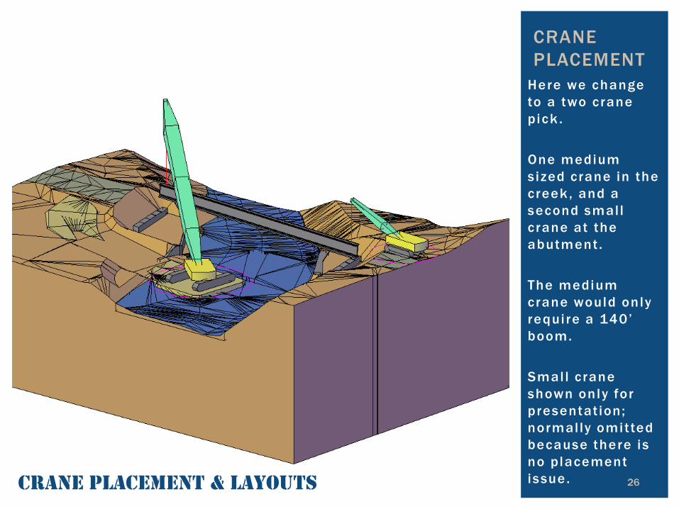
Here we change to a two crane pick . One medium s ized crane in the creek , and a second small crane at the abutment. The medium crane would only requi re a 140’ boom. Smal l crane shown only for presentat ion; normally omitted because there is no placement issue. 26 crane placement & layoUts
CRANE PLACEMENT

Here we change to a two crane pick . One medium s ized crane in the creek , and a second small crane at the abutment. The medium crane would only requi re a 140’ boom. Smal l crane shown only for presentat ion; normally omitted because there is no placement issue. 27 crane placement & layoUts
CRANE PLACEMENT

Steel Beam End Repairs
28
CONSTRUCTABILITY OF DETAILS
MODELING FOR STRUCTURES

Failed joint material over this pier caused severe deterioration to the fascia beam.
29
CONSTRUCT-ABILITY OF DETAILS
eXisting conDition

Proposed construction detai led to l imit changes to the exist ing structure.
30
CONSTRUCT-ABILITY OF DETAILS
eXisting conDition

The severely deteriorated steel is removed along with a por t ion of the diaphragm connection plate to al low for the proposed steel repair.
31
CONSTRUCT-ABILITY OF DETAILS
eXisting conDition removal section

A WT section is modified to replace the removed section of girder and web plates are instal led to provide a connection as well as st i f fening to the web.
32
CONSTRUCT-ABILITY OF DETAILS
proposeD repair – aDD wt section proposeD repair – aDD fill plates to web proposeD repair – Drill holes to match

Flange angles are instal led and the repair is bolted together. 3D model may help identify any constructabi l i ty issues with a detai l that can be resolved prior to construction.
33
CONSTRUCT-ABILITY OF DETAILS
proposeD repair – aDD flange angles proposeD repair – bolt the repair together proposeD repair

Failed deck joint over this pier caused local ized deterioration to the beam ends and bearings.
34
CONSTRUCT-ABILITY OF DETAILS
eXisting conDition

3D model may also help identify structural issues with a proposed detai l .
35
CONSTRUCT-ABILITY OF DETAILS
eXisting conDition Jack sUperstrUctUre (Jacking not shown) remove Deterioration Drill bolt holes anD aDD anchor bolts aDD new bearings anD sole plates shim oUt past web-flange fillet angles bolteD in place to replace flange sUperstrUctUre lowereD conceptUal Detail
Bearing stresses are focused to one location - not a desirable detail.

Aluminum Tri -Chord Truss Sign Structure Rehabil itation
36
CONSTRUCTION SEQUENCING
MODELING FOR STRUCTURES

The exist ing structure had weld cracks at the L7 & L8 joints. The L8 joint wi l l be examined fur ther.
37
CONSTRUCTION SEQUENCING
elevation view

The cracks occurred where the green post from Mid-chord Node 8 ends at Low-Chord Node 8, and the brown post from Upper-Chord Node 8 terminates at Low-Chord Node 8.
38 isometric view
CONSTRUCTION SEQUENCING

Ultimately, the final plans wil l show 2D projections of the plates. The goal is not to provide a 3D rendering, but to provide a confl ict free plan set in 2D.
39 final 2D Detail presenteD on plans
CONSTRUCTION SEQUENCING

Here is a zoomed-in view of the joint. Non-relevant members have been removed. The exist ing spl ice is shown because it prevents us from plating the joint from the lef t side.
40 eXisting conDition
CONSTRUCTION SEQUENCING

To begin, the four bolts that wil l connect the lower chord to the front gusset plate must be inser ted.
41 2nD plate’s bolts inserteD
CONSTRUCTION SEQUENCING

Then the fi l l plate and lower gusset plate can be placed. This 1st gusset would have prevented the low chord bolts from being inser ted.
42 1st gUsset & fill plate aDDeD
CONSTRUCTION SEQUENCING
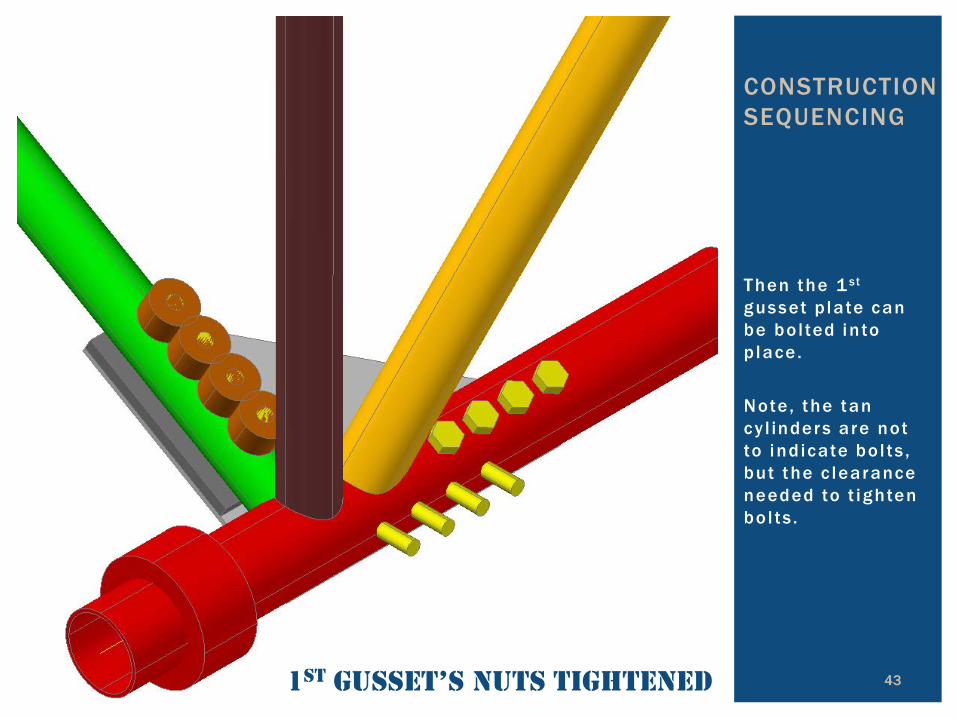
Then the 1 st gusset p late can be bo l ted into p lace. Note , the tan cy l inders are not to ind icate bo l ts , but the c learance needed to t ighten bo l ts .
43 1st gUsset’s nUts tighteneD
CONSTRUCTION SEQUENCING

Now the front gusset plate can be placed in the same sequence as the lower one. Note, bolt holes are not shown because they are not needed to identify the sequencing.
44 final proposeD conDition
CONSTRUCTION SEQUENCING

Complexity of Strip Seal Dam Geometry
45
QUICK GEOMETRY VERIFICATION
MODELING FOR STRUCTURES

Example Bridge A 2-span steel curved girder, over a divided highway. The strip seal joint at the pier requires replacement. Stations ahead are up the page; near abutment at the bottom & far abutment at the top.
46
QUICK GEOMETRY VERIFICATION
plan view NAB

Example Bridge A 2-span steel curved girder, over a divided highway. The strip seal joint at the pier requires replacement. Stations ahead are to the r ight. Ver t ical curve increases slope over bridge.
47
QUICK GEOMETRY VERIFICATION
elevation view – right siDe
Exaggerated Profile

Example Bridge A 2-span steel curved girder, over a divided highway. The strip seal joint at the pier requires replacement. The deck is in superelevation over the bridge.
48
QUICK GEOMETRY VERIFICATION
typical section

Detai l of end of the str ip seal dam as it terminates in barrier. From BC-767M.
49
QUICK GEOMETRY VERIFICATION

When the deck is curved, in plan or profi le, the chords between break points are not straight but ver t ical arcs.
50
QUICK GEOMETRY VERIFICATION
isometric view

Here we have added in the strip seal dam with i ts embedment studs.
51
QUICK GEOMETRY VERIFICATION
isometric view

We can zoom into the lef t barrier and see that the steel extrusion is very close to the sur face. We can of fset the barrier faces the required ( -2”) clearance, and see that the extrusion does not have suf ficient clearance.
52
QUICK GEOMETRY VERIFICATION
left enD of strip seal Dam

If we zoom over to the back of the r ight side barrier, we see a 10” long stud sticks out of the barrier. We can also see that the steel extrusion extends below the bottom of the overhang.
53
QUICK GEOMETRY VERIFICATION
Bang to fit, paint to
match…
right enD of strip seal Dam

This str ip seal dam was laid out as a chord between the roadway crown and the gutter-l ines. As previously mentioned, i t should real ly be a curved, or at least a series of shor t chords.
54
QUICK GEOMETRY VERIFICATION
section cUt location

This str ip seal dam was laid out as a chord between the roadway crown and the gutter-l ines. As previously mentioned, i t should real ly be a curved, or at least a series of shor t chords. Here we see the dif ferential .
55
QUICK GEOMETRY VERIFICATION
section cUt
Bump at bridge… …phone calls… …headache!

Topic 3
56
WHY DO WE BOTHER?
MODELING FOR STRUCTURES

3D modeling is a Design Tool, not just a presentation novelty Allow CAD Technicians to better assist Engineers Identify conflicts during the design phase to avoid costly change orders during construction Improve communication
57
WHY DO WE MODEL IN 3D?

Precast Box Culvert & Soldier Pile Wall Inter face
58
IMPROVE COMMUNICATION
MODELING FOR STRUCTURES

59
IMPROVE COMMUNICATION
p/c cUlvert with solDier pile wall – 2D moDel
Precast Box Culvert & Soldier Pile Wall Inter face
Gas Line prohibits a conventional end section, therefore soldier pile walls are proposed.
A 3D model can be used to communicate a proposed design solution to the client.

A 3D model is a great way to communicate a concept to the cl ient or others on the design team. It is quickly and easi ly understood. This i l lustration shows how a precast culver t segment could be fabricated and integrated into a soldier pi le wall .
60
IMPROVE COMMUNICATION
worksite after eXcavation & boreD piles precast panels & cUlvert beDDing aDDeD precast cUlvert constrUcteD normally short precast panels close the gap
Owner Concerns: Lack of adjustability. Flange damage in delivery.

A 3D model can be an excel lent tool to better engage the cl ient during the design process.
61
IMPROVE COMMUNICATION
replace precast flanges with steel angles

A 3D model is also an excel lent visual communication tool to better engage the public or local of ficials. A 3D model is much more easi ly understood than a set of 2D plans.
62
IMPROVE COMMUNICATION
visUal commUnication tool visUal commUnication tool visUal commUnication tool visUal commUnication tool

Almost Done…
63
CONCLUSION
MODELING FOR STRUCTURES
Basic types of models and editing commands Structures applications of 3D modeling Why we do 3D models Understand when to use 3D models
64
MODELING BASICS SUMMARY