3d modeling capabilities available in aashtoware bridge ... iowa 3d workshop.pdf · 3d modeling...
TRANSCRIPT

1
3D Modeling Capabilities Available in AASHTOWare Bridge
Design and Rating
Iowa Department of TransportationWorkshop on 3D Design and Modeling for Highway
StructuresApril 15, 2015
2
Topics
1. AASHTOWare
2. Software Overview
3. 3D Features and Capabilities
4. Summary
3
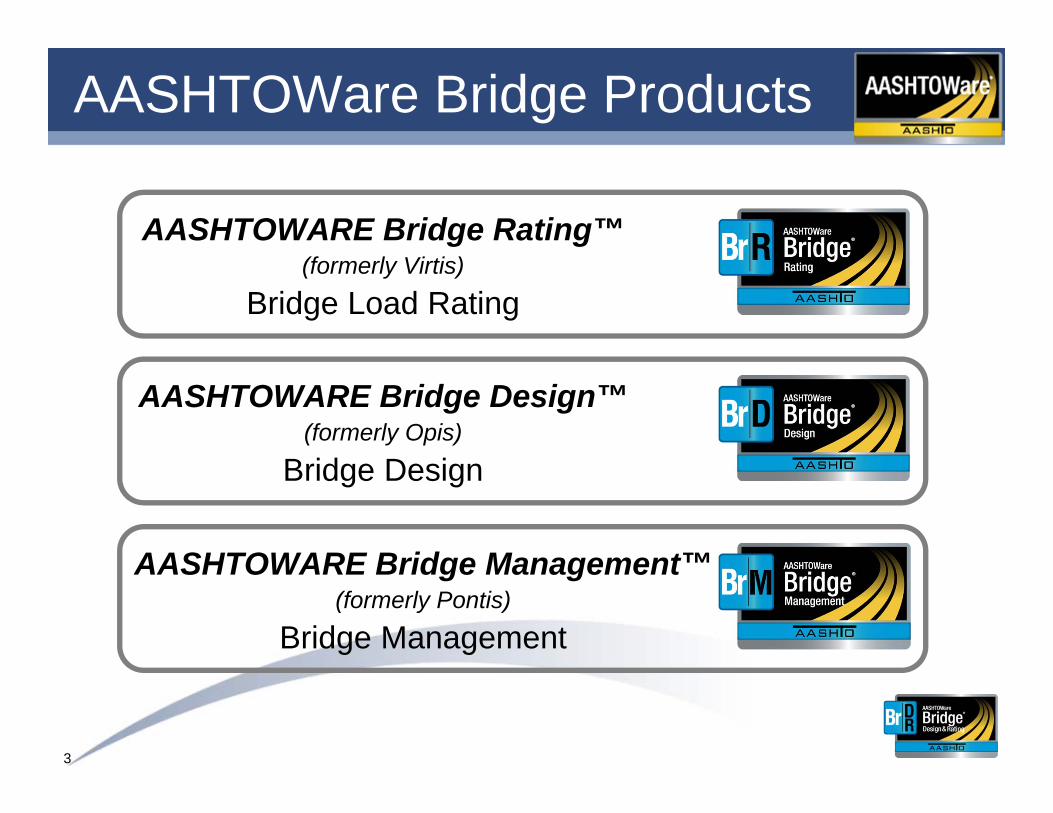
AASHTOWare Bridge Products
AASHTOWARE Bridge Rating™(formerly Virtis)
Bridge Load Rating
AASHTOWARE Bridge Design™(formerly Opis)
Bridge Design
AASHTOWARE Bridge Management™(formerly Pontis)
Bridge Management

4
AASHTOWare
• Joint Development Effort
• Pooled Resources
• Software is owned by AASHTO
• Managed by a Task Force
• Tested by users (Technical Advisory Group)

5
Task Force Members
• Todd Thompson, South Dakota DOT , Chairman
• Dean Teal, Kansas DOT
• Jeff Olsen, Montana DOT
• Amjad Waheed, Ohio DOT
• Joshua Dietsche, Wisconsin DOT
• Judy Skeen – AASHTO Project Manager
• Tom Saad – FHWA Liaison
6
Software Overview
• Product Concept
• Licensees
• Major Capabilities
7
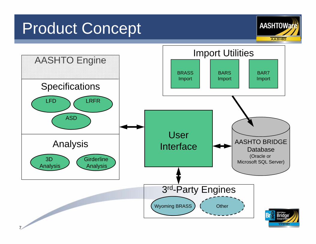
Product Concept
AASHTO BRIDGEDatabase(Oracle or
Microsoft SQL Server)
UserInterface
BAR7Import
BARSImport
BRASSImport
Import Utilities
ASD
AASHTO Engine
LFD LRFR
3D Analysis
GirderlineAnalysis
Specifications
Analysis
Wyoming BRASS
3rd-Party EnginesOther
8
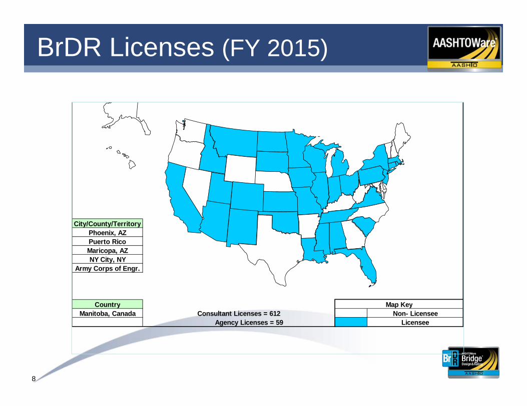
BrDR Licenses (FY 2015)
NY City, NY
Manitoba, CanadaCountry
Maricopa, AZ
Army Corps of Engr.
City/County/TerritoryPhoenix, AZPuerto Rico
Agency Licenses = 59 Licensee
Map KeyConsultant Licenses = 612 Non- Licensee
9
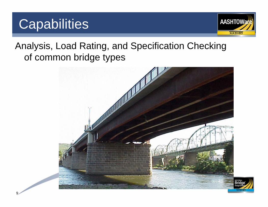
CapabilitiesAnalysis, Load Rating, and Specification Checking
of common bridge types

10
Capabilities
Billerica
Carlisle
Concord
Burlington
Lexington
Lincoln
BedfordNorthRoad
CarlisleRoad
ConcordRoad
SpringsRoad
PineHill
Road
Old BillericaRoad
BurlingtonRoad
PageRoad
PageRoad
ShawsheenRoad
BrooksbieRoad
HartwellRoad
SouthRoad
SummerStreet
HartwellAvenue
The GreatRoad
BedfordRoad
GroveStreet
BedfordStreet
MiddlesexTurnpike
BurlingtonMall
4
4
225
225
62
62
62
3
3
128
128
Support of Permit Routing
11
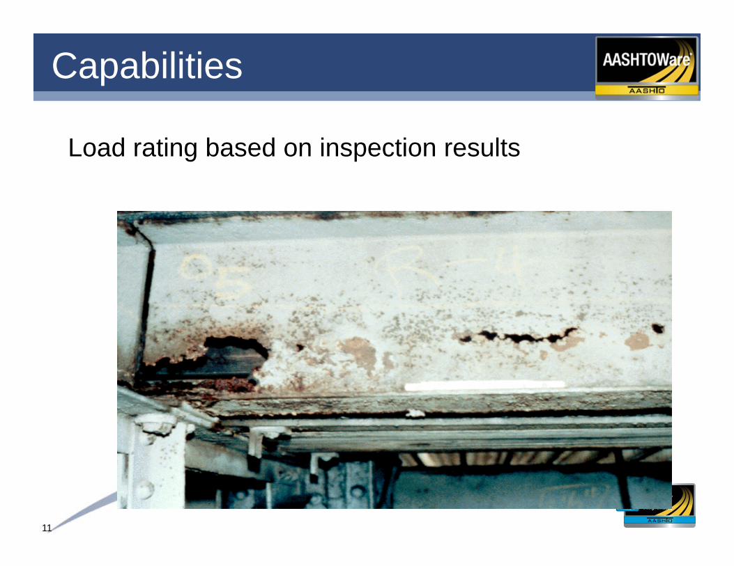
Capabilities
Load rating based on inspection results

12
CapabilitiesComparison validation - enter a bridge once and…
• Compare results between engines
• Compare results between different specifications (ASD, LFD, LRFR, LRFD)
• Compare results between different versions of the LRFD/LRFR specifications
• Compare results between 3D and girder-line analysis
13
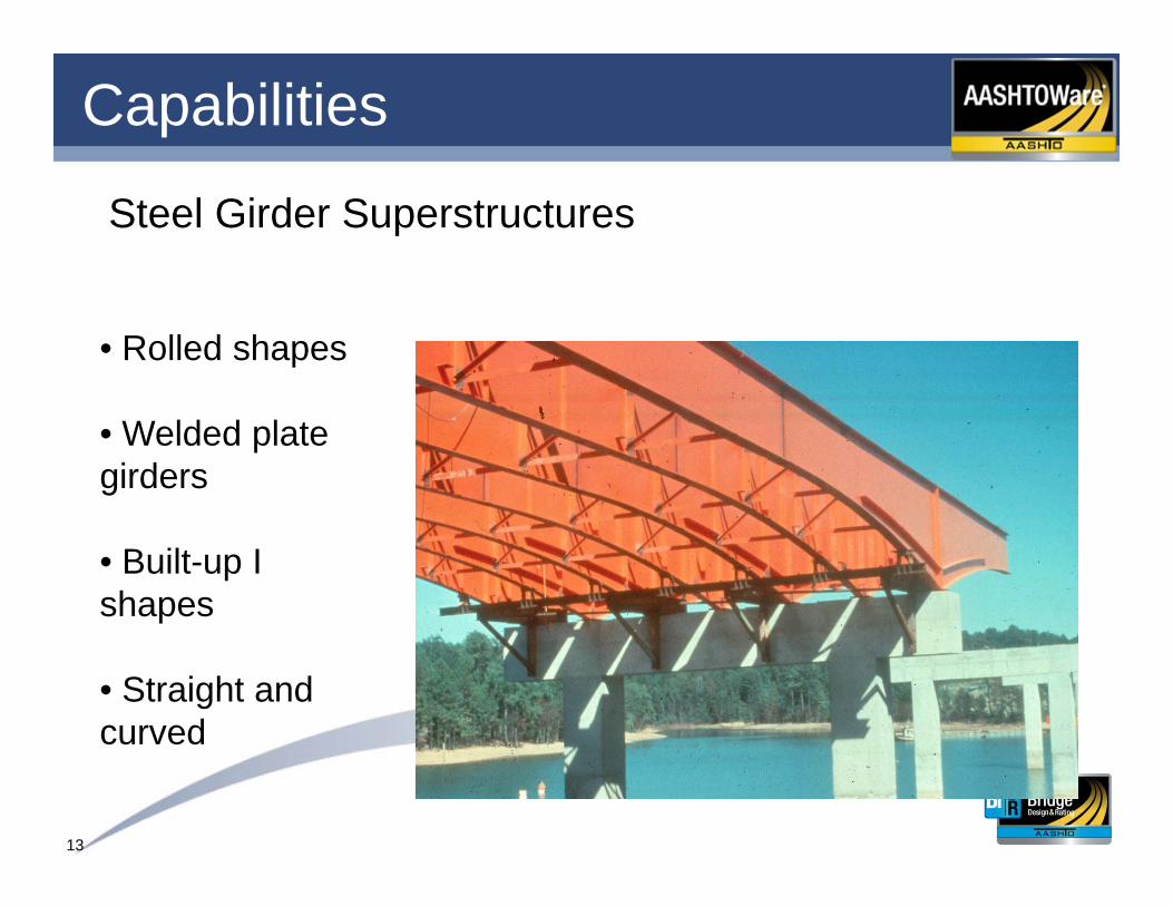
Capabilities
Steel Girder Superstructures
• Rolled shapes
• Welded plate girders
• Built-up I shapes
• Straight and curved
14
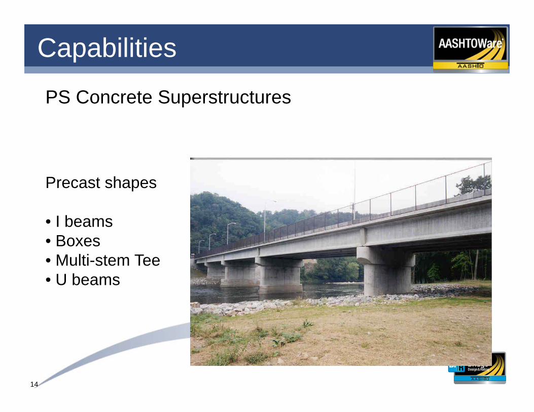
Capabilities
PS Concrete Superstructures
Precast shapes
• I beams• Boxes• Multi-stem Tee• U beams
15
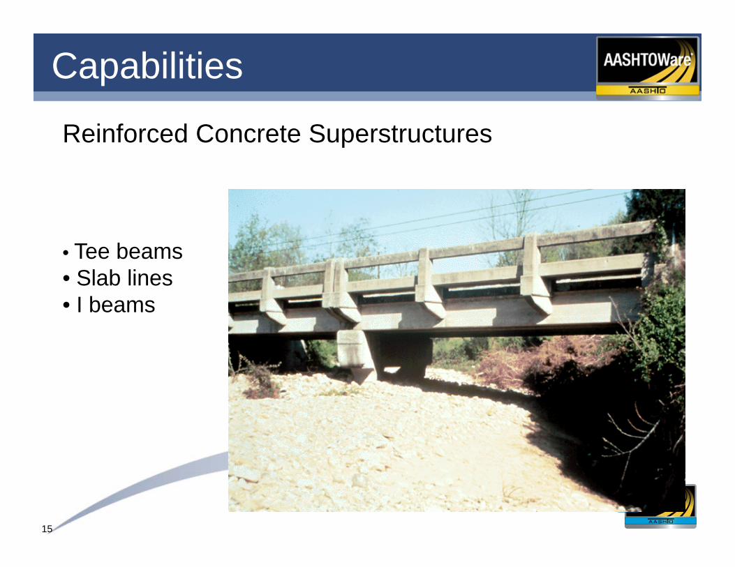
Capabilities
Reinforced Concrete Superstructures
• Tee beams• Slab lines• I beams

16
Capabilities
Reinforced and Post-Tensioned Concrete Multi-Cell Box Superstructures
• LRFD/LRFR
• User-defined box cross sections
• Line girder analysis, full box along with web-lines
• Integral with pier

17
Capabilities – Multi-cell boxes
Reinforced Concrete
Post-tension Concrete

18
Capabilities
Trusses(LFD)
• Continuous spans
• Suspended spans
• Counters
• Deck Trusses
• Through Trusses

19
Capabilities
Floor Systems (ASD and LFD)
• Girder-Floorbeam-Stringer
• Girder-Floorbeam
• Truss-Floorbeam-Stringer
• Truss-Floorbeam
• Floorbeam-Stringer
20
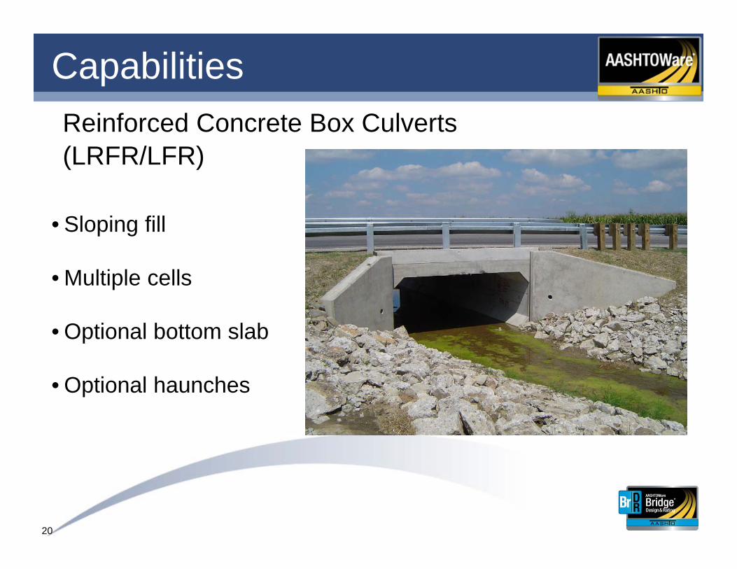
CapabilitiesReinforced Concrete Box Culverts(LRFR/LFR)
• Sloping fill
• Multiple cells
• Optional bottom slab
• Optional haunches

21
Capabilities
3D Analysis
• Straight and curved steel multi-girder systems
• Straight PS and RC multi-girder systems
• Dead and Live loads
• Live load - moves vehicles on influence surfaces to compute maximum and minimum effects
22
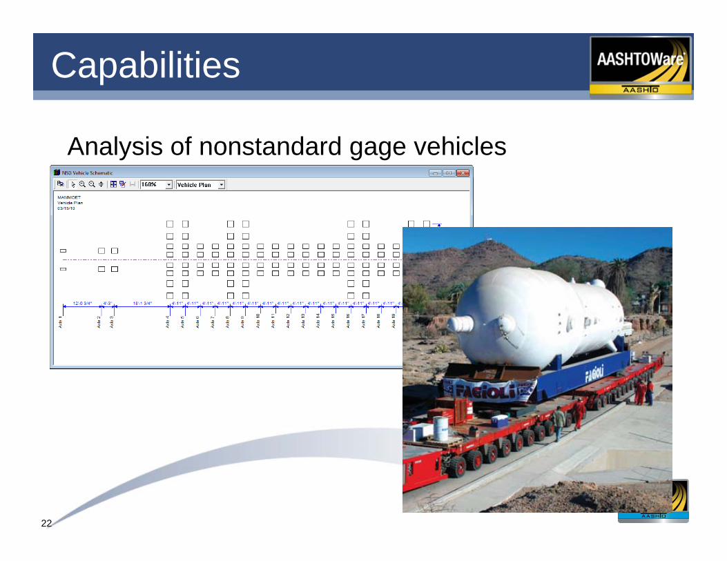
Capabilities
Analysis of nonstandard gage vehicles

23
Capabilities
Non-standard gage analysis
• Describe a non-standard gage vehicleUnlimited number of axlesUnlimited number of wheels per axle
• Describe a loading path for the vehicle
• 3D analysis – loading of an influence surface for live load actions
• Rating

24
AASHTO LRFD Spec Checking
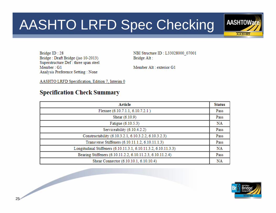
25
AASHTO LRFD Spec Checking

26
Bridge Workspace - DesignLRFD Method of Solution Manual
Includes detailed flow charts
27
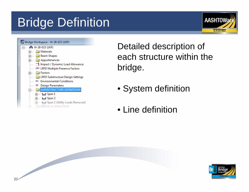
Bridge Definition
Detailed description of each structure within the bridge.
• System definition
• Line definition
28
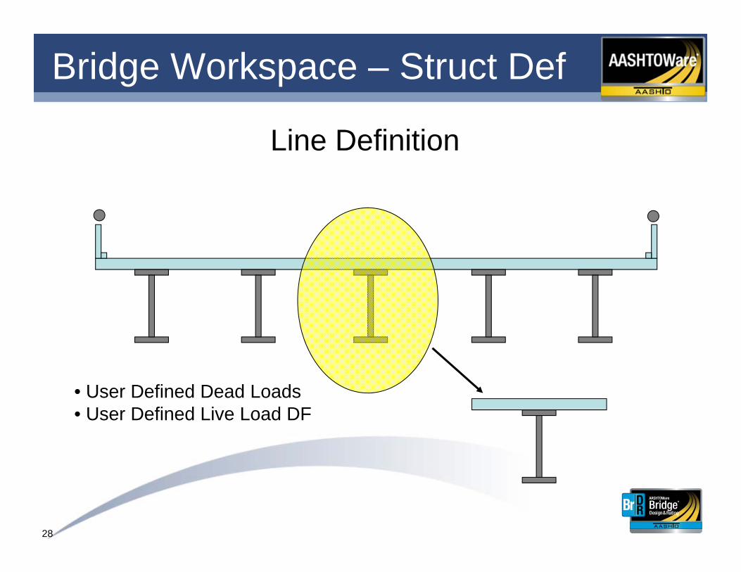
Bridge Workspace – Struct Def
Line Definition
• User Defined Dead Loads• User Defined Live Load DF
29
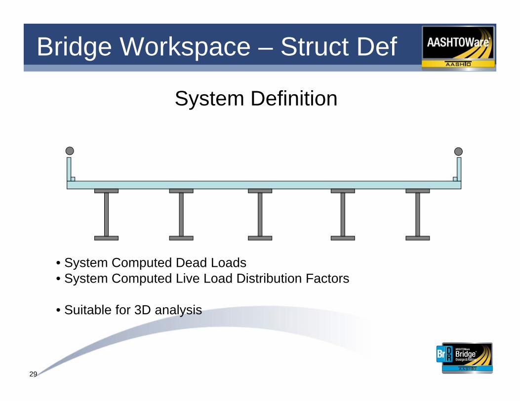
Bridge Workspace – Struct Def
• System Computed Dead Loads• System Computed Live Load Distribution Factors
• Suitable for 3D analysis
System Definition
30
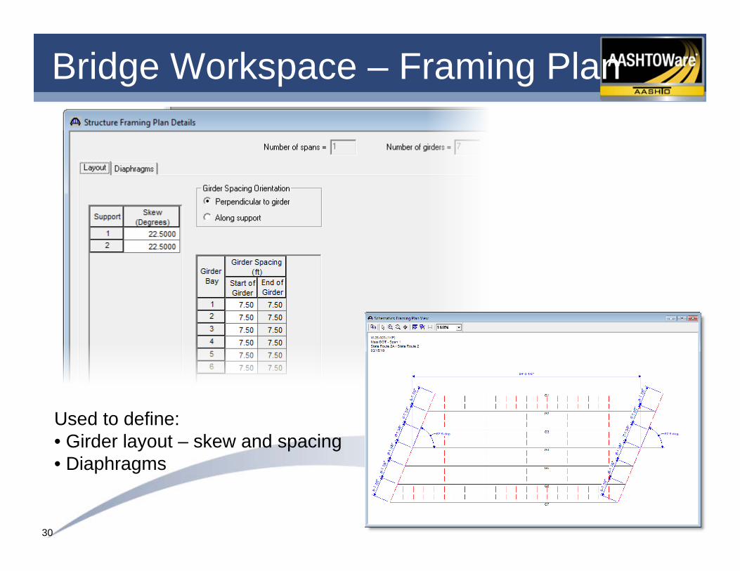
Bridge Workspace – Framing Plan
Used to define:• Girder layout – skew and spacing• Diaphragms
31
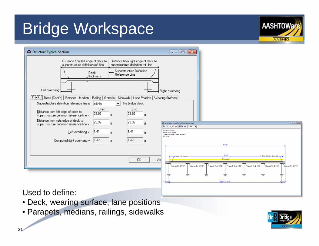
Bridge Workspace
Used to define:• Deck, wearing surface, lane positions• Parapets, medians, railings, sidewalks

32
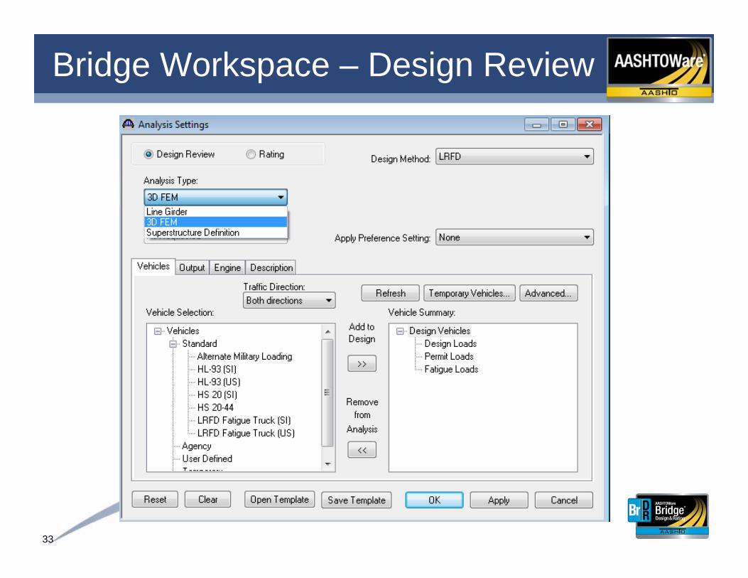
Bridge WorkspaceChoose analysis module and spec version…
33
Bridge Workspace – Design Review
34
3D Features and Capabilities
• Multi-Girder Superstructures
o Steel (Straight or Curved)
o Prestressed Concrete (Straight)
o Reinforced Concrete (Straight)

35
3D Features and Capabilities
• Automated 3D Model Generation for Structural Analysis and Design
• 3D Model Viewer

36
3D Features and Capabilities
• Multi-Girder Superstructures
o Analysis of diaphragms
o Spec-checking and rating of diaphragms coming soon
37
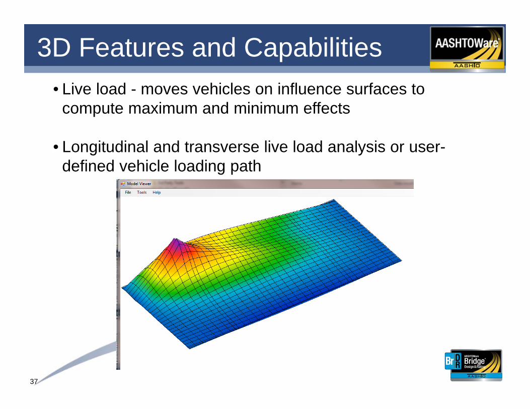
3D Features and Capabilities• Live load - moves vehicles on influence surfaces to
compute maximum and minimum effects
• Longitudinal and transverse live load analysis or user-defined vehicle loading path

38
3D Model GenerationShell elements:
• Are used for the steel girder web and the deck• Have four nodes with six DOFs at each node
Girder Web (Shell Element)(Typ.)

39
3D Model GenerationDeck-to-beam connection:
• Master-slave constraints• Connects center of gravity of deck to girder top
flange
Deck-to-beam Connection (Typ.)
40
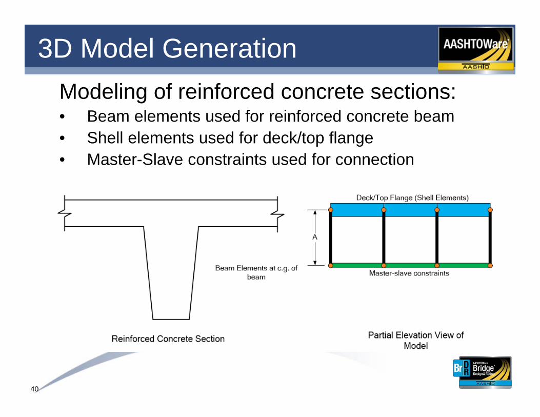
3D Model GenerationModeling of reinforced concrete sections:• Beam elements used for reinforced concrete beam• Shell elements used for deck/top flange• Master-Slave constraints used for connection
41
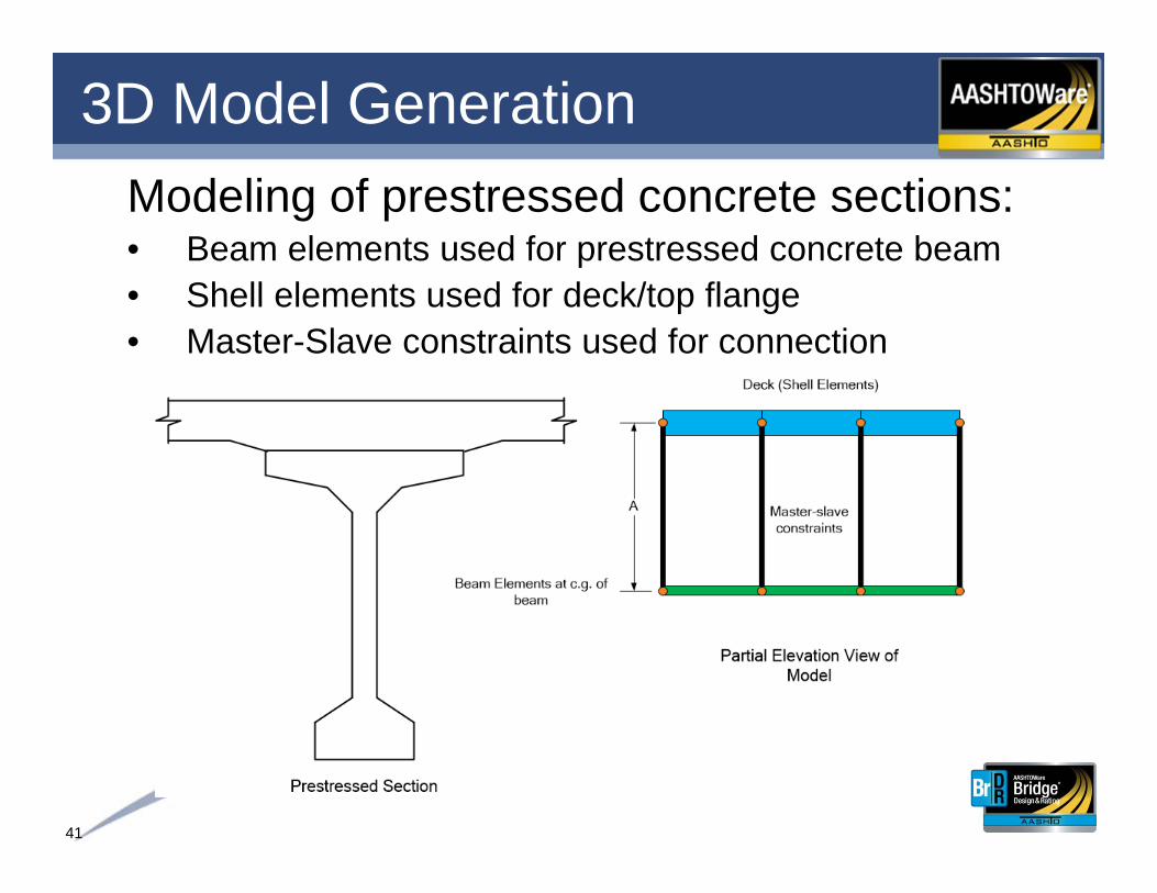
3D Model GenerationModeling of prestressed concrete sections:• Beam elements used for prestressed concrete beam• Shell elements used for deck/top flange• Master-Slave constraints used for connection

42
3D Model GenerationModeling of steel beam with concrete deck:• Beam elements used for steel girder flanges• Shell elements used for deck and steel girder web• Master-Slave constraints used for connection

43
3D Model GenerationSupport conditions:• Free bearings – permit translation in all directions• Guided bearings – permit translation in only one
direction, usually either longitudinal or transverse• Fixed bearings – do no permit translation in any direction

44
3D Model GenerationAnalysis controls: Specify mesh
generation parameters
45
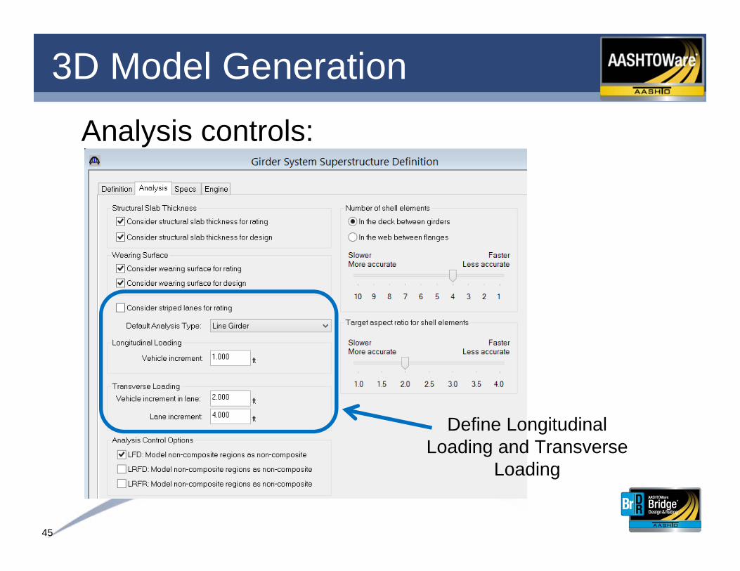
3D Model GenerationAnalysis controls:
Define Longitudinal Loading and Transverse
Loading

46
3D Features and CapabilitiesAnalysis Controls:• Select the diaphragms for which diaphragm forces are to
be computed
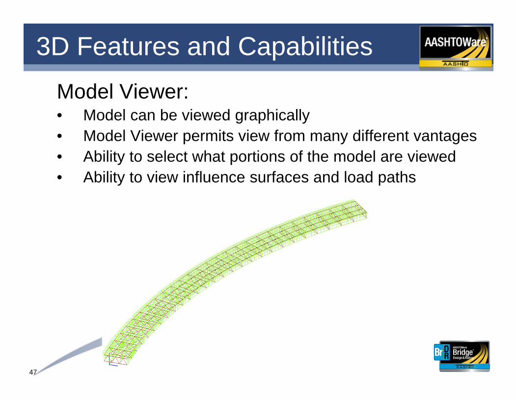
47
3D Features and CapabilitiesModel Viewer:• Model can be viewed graphically• Model Viewer permits view from many different vantages• Ability to select what portions of the model are viewed• Ability to view influence surfaces and load paths
48
3D Features and Capabilities• 3D Finite element analysis based on an investigative
study to identify best practices

49
AwardsAmerican Council of Engineering Companies
2014 National Recognition Award Winner

50
Summary
1. One user interface handles most bridge types and is used for both design review and rating• Improved productivity by learning one user interface• Consistency across many bridge types
2. Database for storing bridge descriptions• Security• Backups
3. Simplified administration of one product

51
Summary
4. General 3D description not specific to:• A particular edition of the AASHTO specification• An analysis method (Line or 3D)• An analysis engine
5. As specifications and methods change the data does not have to be re-input
6. Enter data once and evaluate with different AASHTO specifications (ASR, LFR, LRFR), or different editions of a specification, or different models
52
Summary
7. Research – Evaluate specification changes before they are adopted for production use
8. System allows for 3rd party analysis engines• Wyoming BRASS• Bentley (LARS and former Leap products)
9. Opportunity for agency customization (Service Units)
• Agencies can request features• Users vote on features• Technical Advisory Groups – advise how features
should be implemented

53
Thank you