3com solutions - arp · about this guide this xrn technology and clustered stacking configuration...
TRANSCRIPT

WHITE PAPER
3Com®
Solutions: XRN TECHNOLOGYAND CLUSTEREDSTACKING

ABOUT THIS GUIDEThis XRN Technology and Clustered Stacking Configuration Guideprovides best practices for any technical pre- or post-sales engineerimplementing stacking or clustering within 3Com’s managed switchportfolio running 3Com OS. It is organized in five main sections:
› Overview, Including Definitions, Deployment Examples and ProductCompatibility
› Step-by-Step XRN Stacking Configuration
› XRN Stack Management
› Step-by-Step Clustered Stacking Configuration
› Clustered Stack Management
A list of terms used in this guide appears at the end of this document.
OVERVIEWAs organizations become increasingly dependent on converged networksto provide essential business services to office-bound and mobile users,they must ensure that their communications infrastructures effectivelysupport advanced data, voice and multimedia applications. Selecting anddeploying the right switching technology is imperative because it canhelp companies optimize communications while lowering total cost ofownership (TCO).
3Com XRN stacking and clustered stacking, used independently or intandem, enable companies to centralize the management of their networkswitches, and provide them with the control and flexibility they needat a price they can afford.
CONTENTS
About this Guide.........………………………………………………………………………….…2
Overview ......................................................................................................2
Configuring XRN Stacking..........................................................................7
Managing XRN Stacks ................................................................................8
Configuring Clustered Stacking.................................................................8
Managing Clustered Stacks .....................................................................10
Summary...................................................................................................11
List of Terms .............................................................................................12
3Com Solutions:XRN TECHNOLOGYAND CLUSTEREDSTACKING
Since 3Com invented the stackable form factor in the early 1990’s,it has become the de facto standard for networking vendorsbecause of its flexibility, scalability, and the ability it providesfor companies to cost-effectively upgrade their networks asthey grow. Over the years, 3Com has continued to build on itsinnovation with successive generations of the universallyknown SuperStack® brand. The most recent evolution, whichincludes 3Com’s unique eXpandable Resilient Networking(XRN®) technology, enables up to eight individual switches to be combined as a single switching and routing entity. It allowsnetwork managers to build affordable networks that are highlyresilient, deliver exceptional performance and meet today’sconverged networking demands.
2
3COM SOLUTIONS: XRN TECHNOLOGY AND CLUSTERED STACKING

XRN STACKING DEFINEDXRN technology enables multiple interconnected Gigabit switches tobehave as a single management switching entity, across Layer 2 andLayer 3, acting together to form a Distributed Fabric. XRN technologylogically binds all the functions, performance and resilience together,allowing stackable switches to act like a chassis. And, while traditionalsolutions offer little more than Distributed Device Management (DDM)for stacking, 3Com XRN technology consists of the following three maintechnical components, which help companies to minimize their overallresource requirements and reduce associated costs:
› Distributed Device Management (DDM) – enables the multiple switchesin an XRN stack to operate as if they were a single device on the net-work. DDM lets customers configure and manage all ports and devicesin the XRN fabric as a single entity via the command line interface(CLI), web interface, or simple network management protocol (SNMP).In the event of a failure in one of the switches, management access tothe remaining switch is retained on the same Internet Protocol (IP)address.
› Distributed Link Aggregations (DLA) – allows wiring closet switchesor hosts to create an aggregated link that is dual-homed across theswitches in the XRN fabric. If a port in the aggregated link fails, traf-fic is forwarded via the remaining ports. DLA provides intelligentlocal forwarding, enabling each switch in the fabric to make its ownforwarding decisions without sending traffic across the aggregatedlink.
Features such as DLA enable companies to make sure that their networks continue to operate in the event of equipment or cablingfailures. DLA also allows managers to schedule maintenance duringplanned times that are least disruptive to the company’s operations,rather than undertaking costly emergency repairs during peak times.
› Distributed Resilient Routing (DRR) – lets all switches in the XRNfabric act as a single logical router. The switches use the same routerinterfaces and mirror each other’s routing tables. This protects thenetwork against unit failure and enables each switch to locally routetraffic for greater Layer 3 forwarding performance.
Using DRR functionality allows managers to configure routing for astack of switches so that multiple switches can function as a singlerouting engine. DRR significantly reduces the overall complexityrelated to configuring separate routers. It also helps to ensure thatthere are fewer network issues resulting from misconfigurations.
In order to realize the above-mentioned attributes, all members of the XRN stack must be joined together via special stacking-enabledconnections.
3
3COM SOLUTIONS: XRN TECHNOLOGY AND CLUSTERED STACKING

CLUSTERED STACKING DEFINED3Com’s clustered stacking delivers benefits similar to the single IPaddress management available with XRN stacking. But, rather than theadvanced level of resiliency and network availability contained in XRNtechnology, clustered stacking offers increased scalability and flexibility.Clustered stacking simplifies the method by which a group of otherwiseindividual switches is managed, via a mechanism that is built into theswitches themselves. It enables single IP management for up to 32devices in a single cluster, and allows devices from different productfamilies to be part of the same cluster. Clustered stacking, which does notrequire the use of additional management applications, is an ideal way tomanage a network in logical groups to ensure a consistent managementinterface, even when the groups contain devices from different productfamilies.
A clustered stack includes the following two types of devices:
› Cluster Commander - initiates management control for the wholecluster. A cluster commander must be configured with an IP addressthat is visible from the network management station.
› Cluster Member – all devices that are not cluster commanders areconsidered to be cluster members. Members join a cluster at therequest of a commander once clustering has been correctly enabledon that device.
COMBINING XRN STACKING AND CLUSTERED STACKING3Com OS makes it possible for companies to experience the benefits of both XRN stacking and clustered stacking. Network administratorscan use XRN technology to create highly-resilient topologies and thengroup XRN stacks into clusters, managing them as single entitiesappropriate to the physical configurations of their networks.
The ability to group products from different families is particularlybeneficial when technologies, such as 10/100 and gigabit are mixed onparts of the network. Grouping products enables various technologiesto be managed as if they were part of the same product family.
DEPLOYMENT EXAMPLESXRN stacking simplifies management, and is primarily deployed tomaximize a network’s availability and performance. In contrast, whendeployed by itself, clustered stacking does not have a bearing on anetwork’s operation, but significantly impacts the ease with which a network can be managed. Different rules should be applied to a network design depending on whether XRN stacking or clusteredstacking is in use.
Deploying XRN StackingXRN stacking is specifically designed to provide maximum availabilityfor mission critical networks. The ability to split aggregated uplinksacross multiple devices in a stack, combined with a distributed routingengine and distributed management, allows for the creation of networktopologies where failures in devices or links do not result in noticeableinterruptions to the general operation of a network.
By adding the ability to split aggregated XRN stacking uplinks acrossmultiple devices in a resilient core topology, XRN technology providesa network with unparalleled levels of availability – in excess of the 5“9s” recommended for networks that carry Voice over IP (VoIP) traffic.See Figure 1 for an example of this type of network.
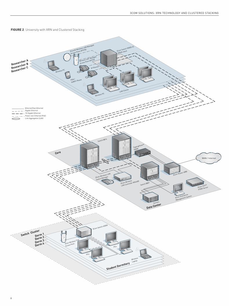
Deploying Clustered StackingClustered stacking allows for multiple devices from various productfamilies to be grouped and managed in a way that best suits the logicaltopology of the network.
For example, in Figure 2, the engineering researchers on a Universitycampus can take advantage of the bandwidth they need to rapidlyaccess applications from email and PowerPoint presentations for engi-neering research, simulations and modeling, enabling them to quicklyshare data and retrieve information on the web. Multiple individualswitches spread across several buildings provide students with reliable,high-speed network access from their dormitories.
While this topology has multiple switches in numerous locations andincludes various switch families, it is likely that configurations will be consistent for all students. In this scenario, grouping all dormitoryswitches into a single cluster enables the network administrator to efficiently change the network configuration for all student accessrather than requiring each switch to be managed individually.
PRODUCT FAMILY COMPATIBILITYIn any network deployment, there are different options available forimplementing XRN stacking versus clustered stacking. The followingtable demonstrates how the 3Com switch families offer support for XRNstacking and clustered stacking:
*Switch Family does not support DLA or DRR
4
3COM SOLUTIONS: XRN TECHNOLOGY AND CLUSTERED STACKING
4200 4200G 4500 4500G 5500 5500G
Clustered Stacking 3 3 3 3
XRN Stacking 3* 3* 3 3

5
3COM SOLUTIONS: XRN TECHNOLOGY AND CLUSTERED STACKING
FIGURE 1: XRN Stacking Deployed in a Mission-Critical Environment
Edge 2
Edge1
Distribution 2
Distribution 1
Core
Data Center
LAN Clients
Wireless PC
3Com Wireless
LAN Controller WX4400
3CRWX440095A Wireless LAN Controller WX4400
3Com Wireless LAN
Switch Manager
Wireless LAN
Switch Manager
IP Phones
Wireless LAN Managed
Access Point AP2750
3Com® Wireless LAN Managed
Access Point AP3750
PDA /
VoWiFi Phone
Wireless PC
PDA /
VoWiFi Phone 3Com Switch 7758
3Com Switch 5500G-EI
XRN® stack
3CR17172-91 SuperStack 4 Switch 5500-EI PWR 52-Port
3CR17172-91 SuperStack 4 Switch 5500-EI PWR 52-Port
3CR17172-91 SuperStack 4 Switch 5500-EI PWR 52-Port
3CR17172-91 SuperStack 4 Switch 5500-EI PWR 52-Port
3CR17172-91 SuperStack 4 Switch 5500-EI PWR 52-Port
3CR17172-91 SuperStack 4 Switch 5500-EI PWR 52-Port
3CR17172-91 SuperStack 4 Switch 5500-EI PWR 52-Port
3CR17172-91 SuperStack 4 Switch 5500-EI PWR 52-Port
Switch 8814
Switch 8807
3Com VCX™
V7000 Server
3Com Router 6080
3Com Enterprise
Management System
TippingPoint™
5000E
Servers
WAN / Internet
Ethernet/Fast EthernetGigabit Ethernet10-Gigabit EthernetPower over Ethernet (PoE)Link Aggregation (LAG)
6
3COM SOLUTIONS: XRN TECHNOLOGY AND CLUSTERED STACKING
Researcher A
Researcher B
Researcher C
3Com Switch 4500G
3CR17562-91 SuperStack 3 Switch 4500 50-Port
3CR17561-91 SuperStack 3 Switch 4500 26-Port
3CR17561-91 SuperStack 3 Switch 4500 26-Port
3CR17561-91 SuperStack 3 Switch 4500 26-Port
3Com Wireless 7760
Access Point
PCs
PCs
Wireless
Laptop
Switch Cluster
Dorm 1
Dorm 2
Dorm 3
Dorm 4
Student Dormitory
Core
Data Center
LAN Clients
Wireless PC
3Com Wireless
LAN Controller WX4400
3CRWX440095A Wireless LAN Controller WX44003Com Wireless LAN
Switch Manager
Wireless LAN
Switch Manager
IP Phones
Wireless LAN Managed
Access Point AP2750
3Com® Wireless LAN Managed
Access Point AP3750
PDA /
VoWiFi Phone
Wireless PC
3Com Switch 5500G-EI
XRN® stack
3CR17172-91 SuperStack 4 Switch 5500-EI PWR 52-Port
3CR17172-91 SuperStack 4 Switch 5500-EI PWR 52-Port
3CR17172-91 SuperStack 4 Switch 5500-EI PWR 52-Port
3CR17172-91 SuperStack 4 Switch 5500-EI PWR 52-Port
3CR17172-91 SuperStack 4 Switch 5500-EI PWR 52-Port
3CR17172-91 SuperStack 4 Switch 5500-EI PWR 52-Port
3CR17172-91 SuperStack 4 Switch 5500-EI PWR 52-Port
3CR17172-91 SuperStack 4 Switch 5500-EI PWR 52-Port
Switch 8814
Switch 8807
3Com VCX™
V7000 Server
3Com Router 6080
3Com Enterprise
Management System
TippingPoint™
5000E
Servers
WAN / Internet
Ethernet/Fast EthernetGigabit Ethernet10-Gigabit EthernetPower over Ethernet (PoE)Link Aggregation (LAG)
FIGURE 2: University with XRN and Clustered Stacking

NUMBERING DEVICES FOR STACKINGWhen stacking switches together, users should decide whether they aregoing to set the unit numbering to ensure that the same units alwayshave the same number within the stack, or if, for ease of deployment,they are going to allow units to automatically number themselves.
Unit numbering can be controlled on individual units or on units thathave already joined a stack.
Return a unit to its factory default of auto-numbering with this:[5500-EI] change self-unit to auto-numbering
If manual unit numbering is required, use the following to ensure thatnumbering within a stack remains consistent when units are added toor removed from a stack:[5500-EI] change self-unit to <unit_number>
Use the following if other units in a stack are to be re-numbered:[5500-EI] change unit-id <current_unit_number> to <new_unit_number>
Once numbering changes for a unit or units in a stack is complete, thechanges should be saved. Use the following to preserve the changesacross a reboot:<5500-EI> fabric save-unit-id
STACKING STATUSOnce a stack has been successfully created and all units have joined thestack, use the following to check on the status of the stacking fabricfrom the CLI:[5500-EI] display xrn-fabric
Fabric name is 5500-EI, system mode is L3.
Unit Name Unit ID5500-EI 15500-EI 25500-EI 3(*)After the stack has been built, the complete stack can be managed fromthe IP address of any single unit within that stack.
CONFIGURING XRN STACKINGXRN technology can be used throughout an enterprise network to provide high-performance, highly fault-tolerant backbones, Gigabit-over-copper aggregation, and Layer 3 switching. After configuration, all switches actively share routing intelligence and network loads—eliminating the wasted bandwidth and added expense of a passivestandby unit. Ultra-fast failover recovery automatically redistributestraffic among the other active units if a switch becomes disconnected.
There are two basic ways to implement XRN stacking:
› Local XRN stacking connection. Switches can be configured locally in a resilient XRN stacking configuration, with both switches typicallyresiding in the same rack.
› Distributed XRN stacking connection. Switches can be remotely connected up to 70Km apart using a fiber connection.
Regardless of whether local or distributed XRN stacking connectionsare used, 3Com switches that support XRN stacking must adhere to thefollowing four main rules:
1.All devices must be from the same product family.Only models from the same product family can be stacked together.The 3Com Switch 5500-EI series and the 3Com Switch 5500G-EI seriesare the two 3Com families that currently support full XRN stacking.
2.All devices must have the same installed versions of software.Before deploying a stack, all devices should be checked to ensure theyare running the same version of software. If they are not the same, acommon software version should be chosen, copied to all units and setas the next boot code before the units are deployed in the stack.
New software files should be uploaded to switch flash memory andthen configured as the next boot versions. All specific configurationfiles that are loaded at this time should ensure that the same systemname is used across all units, and that there are no conflicting unitnumbering assignments.
3.All devices must have the same system name.All units destined for each particular stack and loaded with the sameversion of software, must have the same system name. This will be thefactory default, or it can be set manually via the CLI.[5500-EI] sysname <system_name>
4.All devices must have interconnected ports enabled as fabric ports.Depending on the switch, different methods are used to physicallystack the units together; this affects how the fabric ports are enabled.
Switch 5500 10/100 variants are connected using standard front panelGigabit ports. To ensure that all units can successfully join a stack, theuser must set interconnecting ports to their factory default setting,therefore enabling them as fabric ports.[5500-EI] fabric-port GigabitEthernet 1/0/27 enable
[5500-EI] fabric-port GigabitEthernet 1/0/28 enable
(Note: on a 52-Port Switch 5500, ports 27 and 28 will be 51 and 52.)
Switch 5500G Gigabit variants are connected via dual dedicated 48Gbps high-bandwidth stacking ports on the rear panel of the units.
For both 10/100 and Gigabit models, fully-resilient stacking isenabled when the units are daisy chained together and connected in a full ring by adding a stacking connection from the top unit in thestack down to the bottom unit in the stack.
Switch 4500 10/100 models can be stacked using the same method asthe Switch 5500 10/100 models, except without supporting the resilientstack connection. This allows the two free Gigabit connections at thetop and bottom of the stack to be used as resilient uplinks.
7
3COM SOLUTIONS: XRN TECHNOLOGY AND CLUSTERED STACKING

MANAGING XRN STACKSXRN stacking enables multiple physical devices from the same productfamily to operate as a single logical entity that can be managed from asingle IP address via the CLI, web interface or SNMP. In the event of afailure in one of the switches, management access to the remainingswitch is retained on the same IP address.
3COM OS CLIFeatures such as routing, multicast support and spanning tree, which areglobal to a stack of switches, only need to be enabled once in the 3ComOS CLI for the entire stack. All commands in the 3Com OS CLI relating to port specific configuration are structured so that they can easily scalewhen an individual unit is connected to an XRN stack of devices. Allsuch commands use the xx/yy/zz port numbering format, where xx isthe unit number within the stack, yy is the slot number for modularproducts (always “00” for stackable switches) and zz is the port numberwithin unit xx. The xx/yy/zz format enables all ports in a stack to beconfigured without having to connect to multiple units. When connect-ed to one device in a stack, it is possible to control features and applyattributes to ports on other units, purely by changing the value of xxin the command line. For example, to display the status of port 10 forunit 3 in a stack the following command is used:[5500G-EI] display interface ethernet 3/0/10
SNMPThe single logical entity that is created when multiple switches arelinked to create a stack enables that stack to be managed from anystandard SNMP management software as a single entity.
For example, when viewing a stack of Switch 5500G-EIs on a 3ComNetwork Director topology, each stack is shown as a single device,rather than a group of connected devices as is the case with a cluster.
CONFIGURING CLUSTERED STACKINGClustered stacking technology from 3Com enables effective centralizedmanagement of 4500G switches, and also clusters that include switchesfrom the 4200 and 5500 families. Deploying clustering is a relativelysimple process that involves the following steps:
› Divide the switches into logical groups.
› Select a commander for each cluster.
› Configure the cluster management VLAN.
› Define the scope of the cluster.
› Enable clustering on the commander.
› Build the cluster.
› Enable clustering on the other switches in the cluster.
› Re-build the cluster.
DIVIDE THE SWITCHES INTO LOGICAL GROUPS.All of the elements related to the division of switches into logicalgroups are beyond the scope of this paper. However, the below itemsneed to be considered:
1.All devices must be from 3Com Switch Families that support clustering.Models from the various product families that support clustering canbe stacked together. The 3Com Switch 4500G series, 5500 series and5500G series all support clustered stacking for up to 32 devices; theSwitch 4200G series supports up to 16 devices.
2.All switch devices must have direct access to the same Layer 2 broadcast domain.All units intended to be part of a particular cluster must have directaccess to the same Layer 2 broadcast domain. Providing this accessensures that devices can communicate directly with one another atLevel 2, and helps companies avoid security issues that can arisewhen trusted and untrusted devices share the same broadcastdomain.
3.Ports connecting clustered devices must be members of the same“cluster management VLAN.”Ports connecting devices that intend to be part of the same clustermust be members of the same “cluster management VLAN.”
4.Each cluster must be configured with its own unique “cluster management VLAN.”Multiple clusters can exist on the same broadcast domain, but eachcluster must be configured with its own unique “cluster managementVLAN.”
SELECT A COMMANDER FOR EACH CLUSTER.There are no designated rules for selecting a commander, but certainfactors can be considered, such as choosing the aggregation switch fora wiring closet.
CONFIGURE THE CLUSTER MANAGEMENT VLAN.By default, 3Com OS uses VLAN 1 as the cluster management VLAN. If an alternative VLAN must be used, it should be configured beforeclustering is enabled. An alternate VLAN could be needed due to security or other reasons, such as the deployment of multiple clustersin the same broadcast domain.
If an alternate VLAN is required, it must first be created. For example:[5500G-EI] vlan 2
[5500G-EI-vlan2] description Cluster_Management_VLAN
Next, an IP address must be added to the interface of the chosen man-agement VLAN so that the cluster can be accessed across the network:[5500G-EI-vlan2] interface vlan 2
[5500G-EI-Vlan-interface2] ip address 192.168.1.1 24
[5500G-EI-Vlan-interface2] quit
Note: If there is a requirement to manage all devices in a cluster from a centralized SNMP managementtool, then the ports that link the devices in that cluster must be set to the hybrid type.
The new VLAN must be specified as the management VLAN of theswitch:[5500G-EI] management-vlan 2
The new VLAN must be specified as the VLAN interface through whichthe cluster management will be performed:[5500G-EI] cluster
[5500G-EI-cluster] nm-interface vlan-interface 2
[5500G-EI] quit
DEFINE THE SCOPE OF THE CLUSTER.The scope of the cluster should be considered before the cluster isbuilt. The scope can be constrained by defining how many devices thecommander will look across to join to the cluster. This is specified interms of hop count:[5500G-EI] ntdp hop 2
8
3COM SOLUTIONS: XRN TECHNOLOGY AND CLUSTERED STACKING
ENABLE CLUSTERING ON THE COMMANDER.Once the management VLAN has been chosen and configured and thescope of the cluster has been defined, clustering can be enabled on thedesignated commander:[5500G-EI] cluster enable
Then, assign the private IP address range that the commander will useto communicate with all devices in the cluster: [5500G-EI] cluster
[5500G-EI-cluster] ip-pool 192.168.1.1 24
Note: although the pool of addresses can be re-used, it is recommended that each cluster in a network isgiven a unique pool of IP addresses to ensure no address conflicts occur when the clusters are managedvia SNMP.
BUILD THE CLUSTER.The commander can now be instructed to build the cluster: [5500G-EI-cluster] auto-build
Restore topology from local flash file, for there is no base topology.
(Please confirm in 30 seconds, default No). (Y/N) N
The commander will prompt the user to enter an identifying name forthe cluster: Please input cluster name: GR_1
If there are no connected devices that support clustering, or clusteringhas not been enabled in devices that are connected, the following resultwill be returned: Collecting candidate list, please wait...
Candidate list:
Name Hops MAC Address Device
Processing...please wait
Cluster auto-build Finish!
0 member(s) added successfully.
At this point, if the commander is asked to display a list of all membersof the cluster, it will show itself as the only member: [GR_1_0.5500G-EI-cluster] display cluster member
SN Device MAC Address Status Name0 3Com Switch 5500G-EI 48-Port 0016-e0d6-7d00 Admin GR_1_0.5500G-EI
Notice that an additional “_0” is added to the cluster name. It denotesthe device number within the cluster, with “0” always being reservedfor the commander.
ENABLE CLUSTERING ON THE OTHER SWITCHES IN THE CLUSTER.Because clustering is disabled on the switches by default, the othermembers of the logical group now have to be enabled for clustering:
Member 1:[5500-EI] cluster enable
Member 2:[4200G] cluster enable
When the commander is again asked to list all members of the cluster,it will show that these units have joined the cluster:[GR_1_0.5500G-EI] display cluster member
SN Device MAC Address Status Name0 3Com Switch 5500G-EI 48-Port 0016-e0d6-7d00 Admin GR_1_0.5500G-EI
1 3Com Switch 5500-EI 0012-a992-9d01 Up GR_1_1.5500-EI
2 3Com Switch 4200G 48-Port 0016-e0f7-c480 Up GR_1_2.4200G
In certain deployments, it may be easier to globally enable all devicesfor clustering and then exclude some devices from being added to thecluster. In these cases, it is possible to use the “black-list” feature toexclude specific devices by MAC address:[GR_1_0.5500G-EI] cluster
[GR_1_0.5500G-EI-cluster] black-list add-mac 0012-a992-9d01
Inserted the MAC to the black-list successfully!
[GR_1_0.5500G-EI-cluster]
Member 0012-a992-9d01 in cluster is deleted.
Displaying the member list confirms that the unwanted device has beenremoved from the cluster:[GR_1_0.5500G-EI-cluster] display cluster member
SN Device MAC Address Status Name0 3Com Switch 5500G-EI 48-Port 0016-e0d6-7d00 Admin GR_1_0.5500G-EI
2 3Com Switch 4200G 48-Port 0016-e0f7-c480 Up GR_1_2.4200G
Devices explicitly excluded from a cluster can be confirmed from anydevice in that cluster by viewing the contents of the black-list:[GR_1_0.5500G-EI-cluster] display cluster black-list
Device ID Access Device ID Access port0012-a992-9d01 0016-e0d6-7d00 GigabitEthernet1/0/14
If the network topology changes and a device previously excludedfrom a cluster is removed from the network or subsequently requiredto join that cluster, the device can be removed from the black-list:[GR_1_0.5500G-EI-cluster] black-list delete-mac 0012-a992-9d01
Deleted MAC from the black-list successfully!
[GR_1_0.5500G-EI-cluster] display cluster black-list
The black-list is empty now!
RE-BUILD THE CLUSTER.Once clustering has been successfully enabled on the other switches,the commander can be instructed to rebuild the cluster with all availablemembers:[GR_1_0.5500G-EI-cluster] auto-build
Collecting candidate list, please wait...
Candidate list:
Name Hops MAC Address Device5500G-EI 1 0012-a992-9d01 3Com Switch 5500G-EI
Processing...please wait
Member 0012-a992-9d01 is joined in cluster GR_1.
Cluster auto-build Finish!
1 member(s) added successfully.
Displaying the member list confirms that the previously excludeddevice has joined the cluster:[GR_1_0.5500G-EI-cluster] display cluster member
SN Device MAC Address Status Name0 3Com Switch 5500G-EI 48-Port 0016-e0d6-7d00 Admin GR_1_0.5500G-EI
1 3Com Switch 5500-EI 0012-a992-9d01 Up GR_1_1.5500-EI
2 3Com Switch 4200G 48-Port 0016-e0f7-c480 Up GR_1_2.4200G
[GR_1_0.5500G-EI-cluster]
After the cluster is configured and the correct members are includedand excluded, the configuration is complete and the cluster can bemanaged from the single IP address that was assigned to the clustercommander at the beginning of the cluster configuration procedure.
9
3COM SOLUTIONS: XRN TECHNOLOGY AND CLUSTERED STACKING
MANAGING CLUSTERED STACKSClustered stacking enables multiple devices from different productfamilies to be managed as a single logical entity either via their CLI,web interface or SNMP.
3COM OS CLIOnce a cluster has been created, all devices in the cluster can be managedby connecting to a single unit. Clusters are implemented so that allmembers of a cluster become an extension of the CLI of the clustercommander. That is, once a CLI connection has been established withthe commander, it is possible to manage all other members of the clusterwithout having to connect directly to them.
A combination of display cluster member and switch-to cluster membercommands can be used to identify and then manage the members of thecluster:[GR_1_0.5500G-EI] display cluster member
SN Device MAC Address Status Name0 3Com Switch 5500G-EI 48-Port 0016-e0d6-7d00 Admin GR_1_0.5500G-EI
1 3Com Switch 5500-EI 0012-a992-9d01 Up GR_1_1.5500-EI
2 3Com Switch 4200G 48-Port 0016-e0f7-c480 Up GR_1_2.4200G
Once the switch has been identified, it is simple to view and managethat device using its member number in the cluster. For example, toview the Switch 5500-EI in this cluster, or member “1.” :[GR_1_0.5500G-EI] cluster switch-to 1
Once the command is entered, the command line of the target switch isaccessed and that device can be configured as normal:[GR_1_1.5500-EI]
After the member device configuration changes have been completed,control can be returned to the commander by quitting from the mem-ber device’s command line:[GR_1_1.5500-EI] quit
[GR_1_0.5500G-EI]
Using this method, all members of the cluster can be managed and con-figured from a single management session.
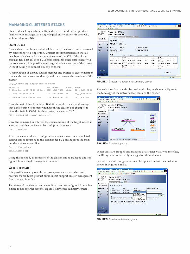
WEB INTERFACEIt is possible to carry out cluster management via a standard webbrowser for all 3Com product families that support cluster managementfrom the web interface.
The status of the cluster can be monitored and reconfigured from a fewsimple to use browser screens. Figure 3 shows the summary screen.
The web interface can also be used to display, as shown in Figure 4,the topology of the network that contains the cluster.
When units are grouped and managed as a cluster via a web interface,the file system can be easily managed on those devices.
Software or unit configurations can be updated across the cluster, asshown in Figures 5 and 6.
10
3COM SOLUTIONS: XRN TECHNOLOGY AND CLUSTERED STACKING
FIGURE 5: Cluster software upgrade
FIGURE 4: Cluster topology
FIGURE 3: Cluster management summary screen

Using the Device Manager allows groups of ports to be selected andenables changes to be applied to all ports in that group with a singlemanagement action.
SUMMARYCompanies can use 3Com XRN technology to build affordable networksthat are highly resilient and deliver exceptional availability. XRN technology, which includes DDM, DLA, and DRR, enables up to eightswitches to be combined as a single switching and routing entity, andallows companies to design and implement core Gigabit backbones thatfeature no single point of failure – a safeguard against hardware,cabling and software failure. The distributed nature of XRN technologytakes full advantage of the high-performance, non-blocking switchingcapacity of each switch in the Distributed Fabric.
On the other hand, clustered stacking provides companies withincreased scalability and flexibility. It allows single IP management forup to 32 devices in a single cluster, and enables various product devicesfrom different product families to be part of the same cluster. Becauseclustered stacking does not require the use of additional managementapplications, it is an ideal way to manage a network in logical groups to ensure a consistent management interface.
3Com XRN technology and clustered stacking can be deployed separately,or implemented collectively to provide companies with a powerful, cost-effective solution that centralizes the management of network switchesand delivers an unprecedented amount of control and flexibility.
SNMPOnce a cluster has been created, it can be identified and managed viaany common SNMP management tool if the management IP interfacehas been set-up on all cluster members.
Figure 7 shows a 3Com Network Director discovered topology map for a network consisting of two separate clusters and the aggregatingswitch that links them. To simplify the example, other interfaces onthe network have been left as undiscovered.
The cluster name and member number are appended to the system namewhen a unit joins a cluster. Therefore, it is easy to use the topology mapto see which units are clustered.
For remote SNMP management with the added benefit of configuringunits via a graphical interface similar to the web interface, it is possibleto use the 3Com Device Manager, either as part of Network Director orstandalone, to view and manage a cluster. Device Manager combines agraphical view of the cluster with graphical representations of the frontpanels of the units in that cluster, simplifying the overall configurationprocedure for port-based features. See Figure 8.
11
3COM SOLUTIONS: XRN TECHNOLOGY AND CLUSTERED STACKING
FIGURE 6: Cluster device upgrade
FIGURE 7: 3Com Network Director discovered topology map
FIGURE 8: 3Com Device Manager

LIST OF TERMS3Com OS – 3Com Operating System
CLI – Command Line Interface
DDM – Distributed Device Management
DLA – Distributed Link Aggregations
DRR – Distributed Resilient Routing
IP – Internet Protocol
MAC – Media Access Control
SNMP – Simple Network Management Protocol – The IETF protocol isused between network management stations and manageable networkdevices. It is used to read (GET) or write (SET) information in an NIC,repeater, switch, router, server, workstation or other network device.Using SNMP, a management station can configure devices, display sta-tistics, detect error rates, identify network changes and gather statusinformation.
TFTP/FTP – Trivial File Transfer Protocol/File Transfer Protocol
VLAN – Virtual Local Area Network – Layer 2 protocol enabling thegrouping of bridge ports, MAC addresses, or IP subnets (depending onVLAN type) into VLAN domains, which then can be assigned specificnetwork privileges. Benefits include confining a broadcast to a specificVLAN and providing a base onto which services can be offered ordenied to specific VLANs. The IEEE 802. 1Q recommendation containsguidelines on VLAN operation.
XRN Technology - eXpandable Resilient Networking
3COM SOLUTIONS: XRN TECHNOLOGY AND CLUSTERED STACKING
Visit www.3com.com for more information about 3Com secure converged network solutions.3Com Corporation, Corporate Headquarters, 350 Campus Drive, Marlborough, MA 01752-30643Com is publicly traded on NASDAQ under the symbol COMS.
Copyright © 2007 3Com Corporation. All rights reserved. 3Com. the 3Com logo and XRN are registered trademarks of 3Com Corporation. All other company andproduct names may be trademarks of their respective companies. While every effort is made to ensure the information given is accurate, 3Com does not accept lia-bility for any errors or mistakes which may arise. All specifications are subject to change without notice. 503183-001-001 02/07