39 ft loop truss installation instructions (all antenna ... · 39 ft loop truss installation...
TRANSCRIPT

39 ft Loop Truss Installation Instructions
(All Antenna Models)
2112 116TH AVE NE SUITE 1-5, BELLEVUE WA, 98004 WWW.STEPPIR.COM TEL: (425)-453-1910 FAX: (425)-462-4415
Rev 2 June 2012

Quantity Part Number
Description
2 10-1601-03 1-3/4” Solid saddles
4 pairs 10-1510-01 Element truss clamp
2 60-0083 4” Stainless turnbuckles
1 60-0110 1/4 x 1-1/4” hex head bolt
1 60-0030 1/4” Nylock nut
2 60-0065 5/16” x 3-1/2” Hex head bolt
2 60-0046 5/16” Nylock nut
2 60-0033 5/16” Washer
1 21-7001-01 75 ft Dacron rope (1 piece)
16 60-0014 #6 Nylock nut
16 60-0014-01 #6 x 7/8” Pan head screw
1 10-1028-01 Anti-Seize packet
1 09-0001 Electrical tape
1 60-0112 Set screw
1 10-1054-01 36” Aluminum truss support
72-0018-31: 2E, 3E, DB18, DB18E, DB36, DB42 Yagi’s
39 ft Truss Kit Parts List Be sure to locate the proper kit part number for your antenna model
Quantity Part Number
Description
2 10-1601-22 2” Solid Saddles
4 pairs 10-1510-01 Element truss clamp
2 60-0083 4” Stainless turnbuckles
1 60-0110 1/4 x 1-1/4” hex head bolt
1 60-0030 1/4” Nylock nut
2 60-0065 5/16” x 3-1/2” Hex head bolt
2 60-0046 5/16” Nylock nut
2 60-0033 5/16” Washer
1 21-7001-01 75 ft Dacron rope (1 piece)
16 60-0014 #6 Nylock nut
16 60-0014-01 #6 x 7/8” Pan head screw
1 10-1028-01 Anti-Seize packet
1 09-0001 Electrical tape
1 60-0112 Set screw
1 10-1054-02 36” Aluminum truss support
72-0018-41: 4E Yagi
Quantity Part Number
Description
2 10-1601-03 1-3/4” Solid saddles
2 60-0083 4” Stainless turnbuckles
1 60-0093 5/16” x 2-3/4” Hex head bolt
4 60-0115 5/16” x 4-1/2” Hex head bolt
5 60-0046 5/16” Nylock nut
2 60-0033 5/16” Washer
1 21-7001-01 75 ft Dacron rope (1 piece)
4 pairs 10-1510-01 Element truss clamp
16 60-0014 #6 Nylock nut
16 60-0014-01 #6 x 7/8” Pan head screw
1 10-1028-01 Anti-Seize packet
1 09-0001 Electrical tape
2 60-0112 Set screw
4 10-1613-01 5/16” ID x 1” spacer
1 10-1618-11 1-3/4” x 30” Truss mast
72-0018-51: DB18E (without optional boom truss)
Quantity Part Number
Description
2 60-0083 4” Stainless turnbuckles
1 60-0093 5/16” x 2-3/4” Hex head bolt
5 60-0046 5/16” Nylock nut
2 60-0033 5/16” Washer
1 21-7001-01 75 ft Dacron rope (1 piece)
4 pairs 10-1510-01 Element truss clamp
16 60-0014 #6 Nylock nut
16 60-0014-01 #6 x 7/8” Pan head screw
1 10-1028-01 Anti-Seize packet
1 09-0001 Electrical tape
72-0018-51: DB18E (with optional boom truss)
IMPORTANT: The DB18E uses two kits.
For the two end elements, the 72-0018-31 kit is used. For the driven element you will use one of two possible kits: 72-0018-51: Use if you did NOT purchase the boom truss kit 72-0018-61: Use if you DID purchase the boom truss kit
Page 2Page 2Page 2Page 2

1. Check and inventory that you received all the parts for the 39 ft 40M/30M truss option. 2. Be sure to use anti-seize on all of the stainless steel fasteners in this step. Failure to do so will potentially cause them to seize. NOTE: for the plastic truss coupler installation, DO NOT use a petroleum based lubri-cant. Teflon plumbers grease works well, available at any hardware store, or Teflon spray like 3M 557. 3. Secure the truss support to the aluminum saddles so that the head of the 5/16” bolt are on the truss support side. (figure 12.02) Secure the truss support and saddle assembly around the boom so that its between the driven EST and return EST (figure 12.01). NOTE: The DB18E truss support for the DRIVEN element is completely different than all of the other antenna models. Refer to page 4 for these instructions. For the two end elements on the DB18E, follow instructions on this page (Pg 3). 4. It is not critical which side of the boom the truss support is on. Use the the boom as a line to sight in the truss support so that it is perpendicular to the boom. This is also not critical as long as you get it as close as possible. 5. Follow the assembly in (figure 12.01) to mount the turnbuckles on the truss support.
6. Follow the steps on page 5 and 6 to assemble the truss couplers and the Dacron truss rope. 7. When the Dacron rope is attached to the turnbuckles and the truss couplers, use the turnbuckles to do any fine-tune adjusting to your element. DO NOT pull the elements up too high on your dipole truss. This will cause the element to collect water and damage your antenna. Do not allow your telescoping poles to make an “S “ shape if looking from the truss support to the sweep. It should be a gradual curve, but the tip of the sweep should never be higher then any other part of the telescoping pole. Lock down the turnbuckle by tightening the small nuts on the turnbuckle.
Page 3Page 3Page 3Page 3

39 ft Truss Installation for DB18E Driven Element ONLY
• The truss support for the DB18E Yagi utilizes 1-3/4” OD aluminum tubing that is mounted directly to
the mast as shown in figure 12.03. The truss mast is secured to the mast plate using 1-3/4” alumi-num saddles.
• Two 4 inch stainless steel turnbuckles are secured to the truss support as shown below.
• This arrangement is only used for the DB18E driven element. For the end elements of the DB18E,
the standard angle brackets are used for supports.
• This truss support is also used if the optional boom truss is purchased for the DB18E.
Phillystran truss
used for optional boom truss kit
QTY 2: 60-0083
4 inch SS Turnbuckle
Dacron Rope
QTY 2: 60-0033
5/16” Nylock nut (One on each side of truss mast)
QTY 1: 60-0107
5/16” x 2-3/4” Hex head bolt
QTY 1: 60-0046
5/16” Nylock nut
Rope
atta
ches
to
plasti
c tru
ss co
upler
QTY 2 (sets)
10-1601-03 Aluminum Saddle
QTY 4: 60-0115
5/16” x 4-1/2” Hex head bolt
QTY 4: 60-0046
5/16” Nylock Nut
Figure 12.03
Page 4Page 4Page 4Page 4
QTY 4: 10-1613-01 Aluminum spacer

Install the truss support couplings
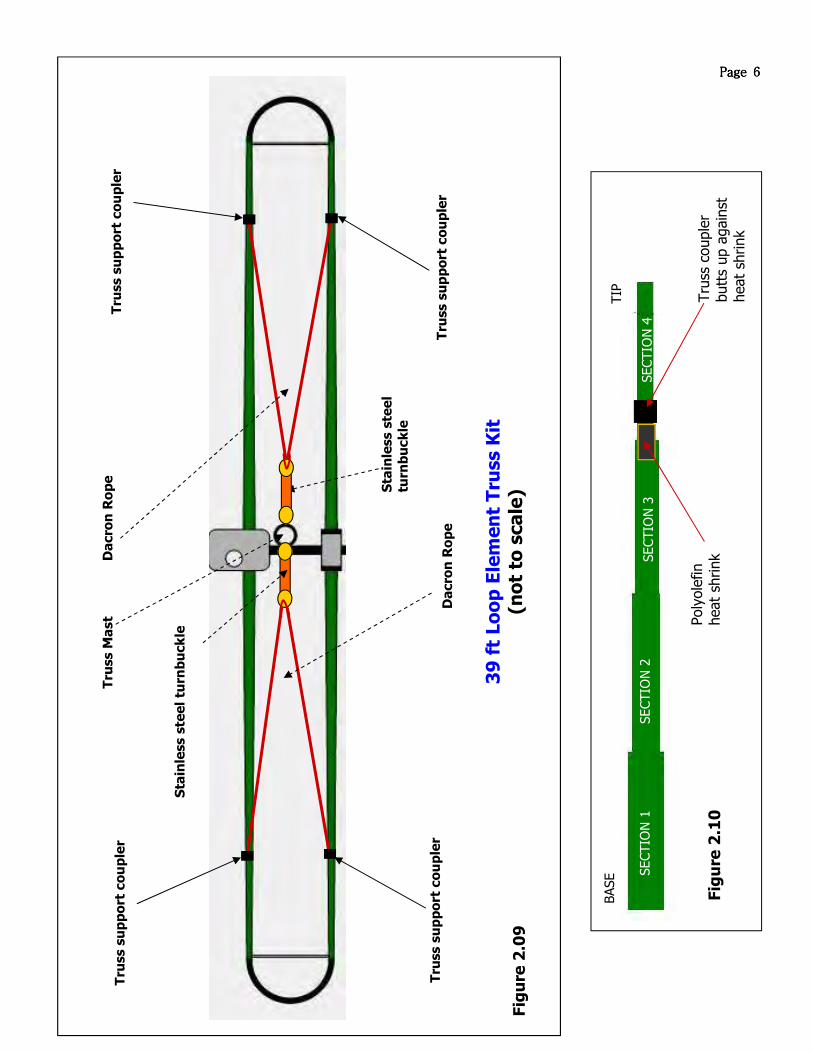
• Each element truss coupler consists of 2 halves as shown in figure 2.01. The truss support couplers (PN 10-1510-
01) are used for fastening the Dacron rope to the last section of the telescoping poles. Figure 2.10 on page 6 pro-vides an expanded view of a truss element assembly.
• When fastening the couplers to the telescoping pole section only the outside 4 holes are used, as shown in figure
2.02. Position each coupler so that it is flush to the polyolefin heat shrink as shown in figure 2.03 and 2.04. DO NOT place the coupler over the polyolefin heat shrink or it will not seat properly. Figure 2.10 on following page shows the location respective to the telescoping pole to mount the truss coupler.
• Tighten the stainless steel screws and Nylock nuts. DO NOT USE ANY ANTI-SEIZE OR OTHER PETROLEUM BASED
LUBRICANTS ON THE FASTENERS FOR THE COUPLERS; PETROLEUM BASED PRODUCTS WILL CATASTROPHICALLY DAMAGE THE COUPLERS. Be sure your couplers are perpendicular to the pole and level before final tightening.
Figure 2.05 shows the coupler when tightened.
• The Dacron rope is provided in a single piece. You will need to trim the pieces to length as you proceed in installing
each half-portion of the truss. Thread the Dacron rope through the single larger hole at the top portion of the coupler as shown in figure 2.06. Secure the rope to the coupler using several half-hitches, leaving approximately 4” extra rope or “leader”. Run the rope up the telescoping pole towards the stainless steel eye-bolt and then thread the rope through the eye-bolt and back down to the truss coupler opposite of the one that is already secured. thread the rope through the hole shown in figure 2.06 so it is tight and the elements are level, with the eye-bolt approximately half way unscrewed. Secure the rope with several half hitches. Trim the rope, leaving approximately 4” of leader.
• Tape the leader to the main truss line as shown in figure 2.07, trim the rope for that portion of the truss and repeat
for the next. There will be more than enough rope. Tape the leader to the other portion of the rope as shown in fig-ure 2.07. Electrical tape works fine for this.
• Figure 2.08 shows the finished coupler with the Dacron rope secured.
THREAD DACRONROPE THROUGH THIS HOLE
Figure 2.01 Figure 2.02 Figure 2.03 Figure 2.04
Figure 2.05 Figure 2.06
Figure 2.07 Figure 2.08
Page 5Page 5Page 5Page 5
Tru
ss s
up
po
rt c
ou
ple
r
Tru
ss s
up
po
rt c
ou
ple
r
Tru
ss s
up
po
rt c
ou
ple
r
Tru
ss s
up
po
rt c
ou
ple
r D
acro
n R
op
e
Da
cro
n R
op
e
Sta
inle
ss s
tee
l
turn
bu
ck
le
Tru
ss M
ast
39
ft
Lo
op
Ele
men
t T
russ K
it
(no
t to
sca
le)
Sta
inle
ss s
tee
l tu
rnb
uck
le
Fig
ure
2.0
9
Poly
ole
fin
heat
shrink
Tru
ss c
ouple
r butt
s up a
gain
st
heat
shrink
Fig
ure
2.1
0
SECTIO
N 1
SECTIO
N 2
SECTIO
N 3
SECTIO
N 4
BASE
TIP
Page 6Page 6Page 6Page 6