3844
DESCRIPTION
3844TRANSCRIPT
The propulsion of a 12 500TEU container ship
No. A8 2006 Journal of Marine Engineering and Technology 3
The propulsion of a 12 500TEUcontainer ship
JS Carlton, Lloyd’s Register, London
The paper considers the propulsion of a 12 500TEU container ship in conceptual termsand builds on the earlier propulsion studies that were published by Lloyd’s Register in2001/2.The cases for single and twin screw hull forms are considered as well as the var-ious trade-offs that inevitably form part of the design process. Conclusions are reachedabout the feasibility of achieving an acceptable propulsion solution.Within the discussionthe problems of rudder erosion are also addressed.The mechanical propulsion aspectsare examined from the points of view of propulsion efficiency, the achievement of accept-able shaft-line vibration behaviour and the static and dynamic alignment characteristics
AUTHOR’S BIOGRAPHYFollowing training as a mechanical engineer and mathemati-cian, John Stephen Carlton served in the Royal NavalScientific Service undertaking research into underwatervehicle hydrodynamic design and propulsors. Five yearslater he joined Stone Manganese Marine Ltd at Greenwichas a propeller designer and research engineer, specialising incontrollable pitch propeller and transverse propulsion unittechnology but also undertaking analysis into other aspectsof ship propulsion technology. In 1975, he joined Lloyd’sRegister, first in the Technical Investigation Department andafter nine years transferred to the Advanced EngineeringDepartment as its Deputy Head. He later moved to thenewly formed Performance Technology Department wherehe initiated and led several research and developmentactivities but subsequently returned, in 1992, to theTechnical Investigation Department as the Senior PrincipalSurveyor and Head of Department. In 2003 Mr Carltonwas invited to become the Global Head of MarineTechnology and Investigation for Lloyd’s Register reportingdirectly to the Marine Director.
During his career he has presented some 80 technicalpapers on several aspects of marine technology, writtenmany ar ticles for technical journals as well as a textbook onmarine propellers and propulsion. Mr Carlton is a DennyGold Medallist of the Institute of Marine Engineers Scienceand Technology and has also won the Stanley Gray Awardfor Marine Technology twice. Additionally, he sits on a num-ber of international and government committees and is avisiting lecturer and external examiner to universities in theUK and abroad. Earlier this year he was awarded the hon-orary degree of Doctor of Science for his contribution tomarine technology and shipping.
INTRODUCTION
The conceptual design and propulsion of large contain-erships was examined and initially reported byLloyd’s Register.1,2 The driver for that early work wasto test the feasibility of current technology to accom-
modate the design of large container ships and to identifywhere, if necessary, further research and development wasrequired. In addition the problem of whether such a ship wouldprovide a cost-effective means of marine transport for contain-ers was considered.1 Since that time a considerable body ofwork has been done internationally and a continuing pro-gramme of further study has been undertaken within Lloyd’sRegister.3 Within these programmes a range of ship sizes hasbeen considered up to and including 18 500TEU ships. Whilesuch large sizes may be developed in the future, current devel-opments of post-Panamax ships are largely governed by thepresent port sizes and their planned developments. Set againstthis background the present paper examines the propulsionaspects of a nominal 12 500TEU container ship.
Lloyd’s Register’s ultra large container ship design study,published in 20021, determined that the largest container shipwhich could be accommodated by the majority of the world'slarge container terminals would have a capacity of around 12500TEU. In order to test this finding to the fullest extent, theoriginal concept design was developed on the assumption thata larger proportion of high cube containers will be carried inthe future than at present. In this context high cube containerswere defined as 9' 6" high, whereas, historically most con-tainers have been 8' 6" in height. Consequently, in keepingwith this definition, the depth of the ship, taken as 29m, wasbased on the following parameters:i. Depth of double bottom (according to the Rule formula) =2.377mii. Height of 9 tiers of high-cube containers = 26.061m
A8 carlton.qxd 12/10/06 3:27 pm Page 3

A ship depth of 29m will also accommodate a mixed stowof 8’ 6” and 9’ 6” containers ten tiers high. Recent analysis ofcontainer types being transported by sea3 indicates that the pro-portion of high cube containers is increasing. This, therefore,tends to vindicate the earlier assumption of high cube contain-ers acting as the basis for defining the capacity of the ultra largecontainer ship. If, however, the ship’s capacity was re-defined interms of standard height containers, then the capacity of thenominal 12 500TEU ship would increase to 13 970TEU.Notwithstanding this increase, it is considered that to use such adefinition within a conceptual study of this type may overesti-mate the earning capacity of the ship compared to today's fleetand, furthermore, it would overestimate the number of contain-er lifts required and, consequently, the turn round time in port.
The single screw, slow speed diesel engine propulsion optionfor container ships is well established and is one that has gainedmuch favour with ship owners and operators. Consequently, thistenet forms the initial starting point of this study and its feasibili-ty is considered in the context of the larger ship sizes. The analy-sis then expands, first to embrace the effects of variations andtrade offs about the standard ship operational conditions ofdraught and speed and then explores the boundary for a singlescrew propulsion design with a reasonable expectation of success.When considering the propulsion of large container ships the pro-peller and rudder need to be considered together since the propul-sion solution adopted for the propeller will have a significantinfluence on the performance of the rudder. Indeed, the develop-ment of a satisfactory rudder design which will be tolerant of theonerous hydrodynamic conditions within which it is required tooperate has been problematic in a number of recent smallerdesigns. Various options are discussed whereby the potential forminimising the occurrence of structural erosion may be achieved.
Within the overall machinery design problem the designof the propulsion shafting is an important consideration.Furthermore, the behaviour of the shafting system requiresexploration under both static and dynamic conditions: the lat-ter embracing aspects of steady state operation, manoeuvringand operation in rough weather. These problems are exam-ined within the context of alignment and the torsional, lateraland axial vibration dynamics.
HULL FORM The trends in container ship principal dimensions are shownin Figs 1 and 2, the former showing overall length while the
latter shows the variations in moulded beam and maximumdraught with nominal ship capacity.
It is clear that the trends in ship design show that mould-ed beam has been steadily increasing to around 46m for a 10000TEU ship while the maximum draught has been main-tained a sensibly constant value at just below 15m. Both theseprincipal dimensions have been constrained by existing portconfigurations: the former by gantry outreach while the latterby water depth. Consequently, the primary variability indimension has been in ship length as shown by Fig 1.
The basis of the developed hull form for the 12 500TEUship2 is still considered valid when viewed against the expe-rience gained with the increasing size of container ships inthe intervening four years. Consequently, relatively few geo-metric changes have been implemented to reflect our currentunderstanding of large container ship hydrodynamic behav-iour. However, the correct selection of operating draught isof particular importance since not only does it determine thepower requirement for the ship, but also has a profoundinfluence on the propeller blade design in terms of therequired blade area and, consequently, the blade chordlengths, section form and rake and skew distributions.Analysis of operational container ship draughts used in serv-ice3 have shown that in recent years a greater equalitybetween eastbound and westbound draughts is achieved forships engaged on the Far Eastern to European trade routesthan was the case some years ago. If this trend persists thenit will have a helpful influence on the propeller design prob-lem since the accommodation of a significant change ofdraught condition over a round trip potentially becomes lessimportant than previously was the case. Therefore, while thedesign draught has been maintained at 15m, a lesser constantoperating draught has been considered for the ship poweringbased upon analysis of the economic and operating trends.The principal dimensions of the ship based on designdraught are shown in Table 1.
Table 1: Principal hull form parameters
Length between perpendiculars Lpp 381.0mLength along the waterline Lwl 384.0mMoulded breadth B(Mld) 57.0mDesign draught Tdes 15.0mBlock coefficient at Tdes 0.630Midship section coefficient at Tdes 0.990Waterplane area coefficient at Tdes 0.786Longitudinal centre of buoyancy at Tdes -2.25% Aft
Numerical optimisation of propeller-hull configurations at full scale
Journal of Marine Engineering and Technology No. A8 20064
0.05.0
10.015.0
20.0
25.0
30.035.0
40.045.0
50.0
5000 6000 7000 8000 9000 10000
Ship nominal capacity (TEU)
Mou
lded
bea
m &
dra
ught
(m
)
Moulded Beam
Draught
200
250
300
350
400
5000 6000 7000 8000 9000 10000
Ship nominal capacity (TEU)
Leng
th o
vera
ll (m
)
Fig 2:Variation of beam and draught with ship capacity
Fig 1:Variation in ship length with capacity
A8 carlton.qxd 12/10/06 3:27 pm Page 4

Based on commercial analyses the nominal operatingdraught for the ship has been taken as 13.5m. At this draughtthe block, midship section and waterplane area coefficientsand the position of the longitudinal centre of buoyancy areshown in Table 2.
Table 2: Hull form coefficients at 13.5m draught
The ship’s bulbous bow has been optimised for the 13.5mparent draught condition at a ship speed of 25kts. Since thefavoured propulsion configuration by owners for large con-tainer ships is the single screw hull form, this has been adopt-ed as the parent hull form for this study.
HYDRODYNAMIC PROPULSION Sea margin is a function of fouling potential and the addedresistance weather allowances. The correct choice of seamargin is a complex issue, particularly in the presentlychanging scene relating to hull coatings in response toenvironmental concerns. Service analysis studies conduct-ed some years ago suggested differing sea margins for dif-ferent sea routes. Harvald4 in pre-improved anti-fouling
times made a distinction between summerand winter operation on the East-Asiaticroute of 15 and 20% respectively. In thecase of the North Atlantic, dependingupon whether east or west passages werebeing undertaken, allowances of up to 15and 30% respectively were proposed. Thesubsequent introduction of anti-foulingpaints improved this situation consider-ably and permitted a reduction in therequired allowances. However, becausesome of the chemicals in the more effec-tive coatings are in the process of beingbanned for environmental reasons the fullpropulsion advantages of those coatingsare not now available to the marine indus-try. Nevertheless, new technologies areemerging and, in particular, silicon basedpaints, although expensive and the sub-ject of a number of full scale trials, poten-tially offer significant propulsion advan-tages. When traditional anti-fouling coat-ings were able to be used typical sea mar-gins ranged between 10 and 15%.Consequently, recognising the develop-ing technologies, the added resistancecharacteristics of modern container shipsand the present trends in the containership industry a 15% sea margin over thetrial condition has been used in this study.
For the 12 500TEU hull form at aneven keel draught of 13.5m the deliveredservice power at the propeller is shown inTable 3 for a ship speed of 25kts. At this
speed the ship’s quasi-propulsive coefficient was estimatedto be 0.74. Additionally, under normal deep water condi-tions some sinkage will occur due to the dynamic pressurefield around the hull: typically this will induce a trim by thebow with a mean sinkage of around 0.5m. The powerrequired at this condition from the engine, allowing forshaft line mechanical losses, is estimated to be 67.3MW.The shaft rotational speed together with the associated pro-peller diameter has a significant influence on the propul-sive efficiency, cavitation development and the radiatedhull surface pressure signatures. Indeed, for a given shipsize there is no unique solution, rather there is a cluster ofsolutions whose acceptability is dependent upon the hullform and final choice of prime mover.
Table 3: Ship power requirements at T=13.5m and Vs=25kts
The ship effective wake field generated by the hull at25kts was estimated from nominal wake characteristics andthe circumferential variations are shown in Fig 3 for the outerpropeller radii; these being the principal flow features gov-erning the outer propeller blade cavitation dynamics. The vol-umetric mean effective, full scale Taylor wake fraction wascalculated to be 0.22.
Condition Delivered power (PD) Rev/minService 65.94MW 90
Block coefficient 0.613Midship section coefficient 0.989Waterplane area coefficient 0.750Longitudinal centre of buoyancy -2.0% Aft
The propulsion of a 12 500TEU container ship
5No. A8 2006 Journal of Marine Engineering and Technology
00.1
0.20.3
0.4
0.50.6
0.70.8
0.91
0 30 60 90 120 150 180 210 240 270 300 330 360
Angular position in propeller disc (deg)
Axi
al v
eloc
ity r
atio
(V
x/V
s)
0.7R0.8R
0.9R1.0R
-1.0
0.0
1.0
2.0
3.0
4.0
0.0 0.2 0.4 0.6 0.8 1.0
Non-dimensional radius (r/R)
Cho
rd (
m),
skew
(m
), p(
r)/D
,thic
knes
s (m
), ra
ke (
m)
& 1
0Cam
ber
(m)
Chord
p(r)/D
Skew
Thickness
Rake
Camber
Fig 4: Propeller blade geometry
Fig 3: Scaled effective wake for the blade outer radii
A8 carlton.qxd 12/10/06 3:27 pm Page 5

The propulsion of a 12 500TEU container ship
Journal of Marine Engineering and Technology No. A8 20066
Based on a slow speed, direct drive diesel engine as theprime mover for the propulsion system, a propeller having adiameter of 9700mm operating at the continuous service rat-ing was designed. The leading characteristics of the propellerare shown in Table 4.
Table 4: Leading propeller dimensions
The radial distributions of chord, thickness, camber, skewand rake are shown graphically in Fig 4. In the tip region ofthe blades the selection of all of the geometric parameters, butparticularly the radial distributions of chord, rake and skew,can have a profound local influence on the development ofthe cavitation and the consequent magnitude and spectralcontent of the radiated hull surface pressures.
The blade number has been chosen as six, principally inorder to control the effects of cavitation. When operating inthe scaled ship effective wake field the margin against pres-sure side cavitation was 0.26KT when operating in the servicecondition and this is considered to represent a satisfactorymargin. With the propeller installed in the hull aperture andlocated such that first, there was sufficient clearance betweenthe propeller and rudder to permit the propeller to be removedwithout disturbing the rudder and, secondly, a clearance of150mm between the blade tips and the ship’s base line, thepropeller-hull clearance was 0.27D. The predicted suctionside blade sheet cavitation extents are shown in Figs 5a and5b for a ship speed of 25kts at the operating draught of 13.5m.
The analysis of the propeller radiated hull surface pres-sures due to the growth and collapse of the sheet cavitation onthe blade suction surfaces suggested that the first and secondblade rate harmonic pressures were of the order of 6.0kPa and2.3kPa respectively. While pressure excitation magnitude isnot the only determinant of excitation force acceptability andboth surface pressure amplitude and phase have to be consid-ered together, such values are thought to be a satisfactorybasis from which to achieve hull structural global and localvibrations of acceptable levels. Within the current state of theart excitation minimisation from the tip vortices is bestapproached from a model testing perspective for a particulardesign configuration. However, this is not without problemswith respect to scaling and when evaluating the results ofmodel tests recall should be made of previous model to fullscale behaviour correlation for similar ships. Full scale meas-urements and observations on smaller container ships haveshown that the tip vortex may interact with the supercavitat-ing sheet cavitation shed from the trailing edge tip region ofthe suction surface of the propeller blade. Fig 6 shows onesuch set of examples undertaken within the recent EU basedEROCAV project in which Lloyd’s Register was a partici-pant. Such interactions induce the vortex to be twisted vio-lently and then to be thrown outwards and forwards from thevortex core. Partial ring vortices may then be produced in thedirection of the twisting motion and, furthermore, during thisprocess it has been noticed that the off-blade sheet cavity vol-
umes reduce significantly leaving only a fine residue ofvapour mist. During this process the cavitating tip vortex canalso reduce in volume: recognising that the cavitating part ofthe vortex is only the visible part of the total vortex system.However, in Lloyd’s Register’s experience the cavitating coreof the vortex generally remains in the flow field, although ina weaker form, as it is convected towards the rudder leadingedge. Cavitation dynamics of this type significantly increasethe risk of broadband excitation being experienced with alsothe attendant risk of higher harmonic excitation beingencountered.
The propeller has been designed to be manufactured fromnickel-aluminium bronze. This material has a good resistanceto cavitation erosion and the requirements and procedures forthe repair of mechanical or cavitation erosion damage arenow well understood, provided suitably qualified organisa-tions and personnel are employed. Using a mean von Misestensile stress of 49MPa the corresponding distributions ofvon Mises stress for the maximum and minimum thrust con-ditions in the propeller disc are shown in Fig 7.
It will be seen that the maximum von Mises stress fieldoccurs just off the top-dead-centre position (180deg). This isdue to the influence of the propeller in-plane wake field flowvelocities. As expected, due to the influence of the chosenskew, the maximum concentrations within the stress fieldtend to occur towards the trailing edge of the blade but notactually on the trailing edge. This is a beneficial characteris-tic since it helps to avoid having the absolute stress maximaalong the trailing edge where porosity and inclusions cansometimes gather during the casting process of the blade.However, if the skew were increased then the tendency forthe stress concentration to move towards the trailing edge ismore pronounced.5
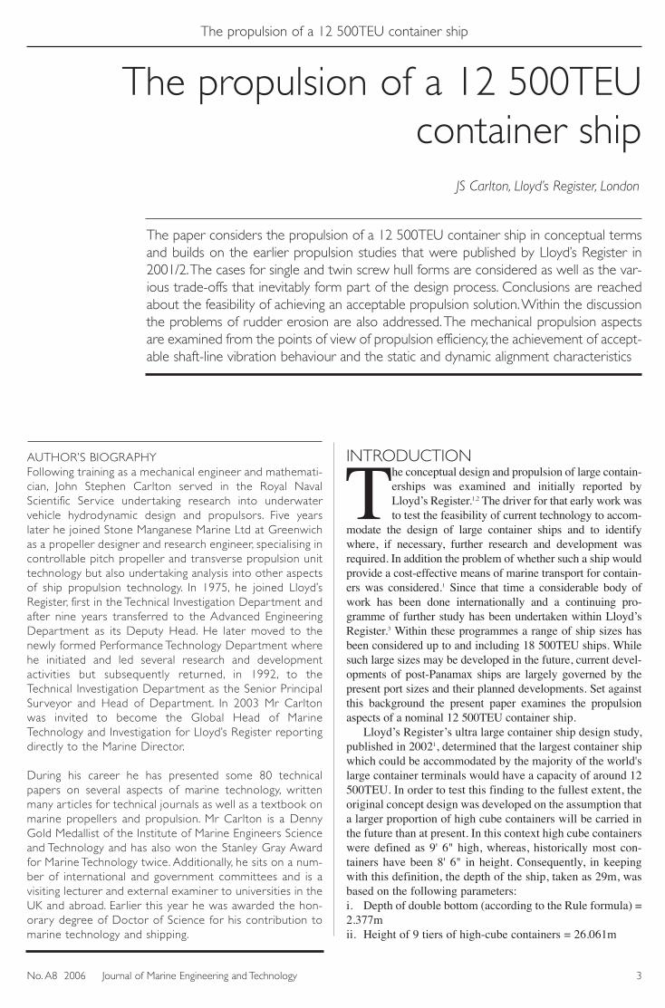
While failure by fatigue action is the dominant considera-tion for ahead propeller operation, during stopping manoeu-vres a yield strength criterion is more appropriate since underthese types of condition for highly skewed propellers theblade is susceptible to bending in the outer regions. Fig 8shows the von Mises stress distribution for a bollard asternloading condition which represents this type of condition atits severest. Given that the 0.15% proof stress of nickel-alu-minium bronze is around 270MPa it can be seen that a bladebending failure situation is unlikely to occur.
TRADE-OFFS IN HYDRODYNAMICDESIGNA number of variants about the basic hull form suggest them-selves as possible contenders for design options. Since beamis essentially fixed by the dockside gantry over-reach, thevariables are principally draught, but recalling that maximumdraught is also a port constraint, and length in order toachieve the same container capacity: recognising that theblock coefficient needs to be as fine as possible within theFroude Number, seakeeping and parametric rolling con-straints. A further variable is ship speed which is a tradingpattern driven requirement.
A variation in draught about the operating draught of 13.5mwas explored over a range of 12 to 15m. This has been done intwo ways: first, by considering the ship to be driven with thepropeller discussed previously and secondly by a purpose
Diameter 9700mmMean pitch ratio 1.038Blade area 0.853Skew 26.5degMaterial Ni-Al BronzeNumber of blades 6
6
A8 carlton.qxd 12/10/06 3:27 pm Page 6

designed propeller for each draught condition. In each case theparent hull has been utilised but with the appropriate hydrostat-ic particulars relating to each draught condition.
In the case where the ship is propelled by the same pro-peller at various draughts, Fig 9 shows the resulting powerabsorption conditions under service conditions for a range ofship speeds between 23 and 27kts. These power absorptioncharacteristics have as a pivot the design condition of the shipwhich relates to a continuous service engine power of 67.3MWand 90rev/min in association with a ship speed of 25kts.
Consequently, for this shipthe continuous service rat-ing forms an upper limit onpower, without modifica-tion to the prime mover,together with an impliedlimitation for the propellersince its stressing basisrelates to the maximum con-tinuous delivered power.
While the hull designhas been optimised aboutthe design point for effec-
The propulsion of a 12 500TEU container ship
7No. A8 2006 Journal of Marine Engineering and Technology
Cavitation Pattern at 150 deg (ITTC Angle)
0.3R
0.9R
0.8R
0.7R
0.6R
0.5R
0.4R
0.95R
Cavitation Pattern at 160 deg (ITTC Angle)
0.3R
0.9R
0.8R
0.7R
0.6R
0.5R
0.4R
0.95R
Cavitation Pattern at 170 deg (ITTC Angle)
0.3R
0.9R
0.8R
0.7R
0.6R
0.5R
0.4R
0.95R
Cavitation Pattern at 180 deg (ITTC Angle)
0.3R
0.9R
0.8R
0.7R
0.6R
0.5R
0.4R
0.95R
Cavitation Pattern at 190 deg (ITTC Angle)
0.3R
0.9R
0.8R
0.7R
0.6R
0.5R
0.4R
0.95R
Cavitation Pattern at 200 deg (ITTC Angle)
0.3R
0.9R
0.8R
0.7R
0.6R
0.5R
0.4R
0.95R
Fig 5a: Predicted suction side cavitation extents from 150 to200degs
Fig 5b: Predicted suction side cavitation extents from 210 to260degs
Fig 7: Propeller blade vonMises stress distributions
Cavitation Pattern at 210 deg (ITTC Angle)
0.3R
0.9R
0.8R
0.7R
0.6R
0.5R
0.4R
0.95R
Cavitation Pattern at 220 deg (ITTC Angle)
0.3R
0.9R
0.8R
0.7R
0.6R
0.5R
0.4R
0.95R
Cavitation Pattern at 230 deg (ITTC Angle)
0.3R
0.9R
0.8R
0.7R
0.6R
0.5R
0.4R
0.95R
Cavitation Pattern at 240 deg (ITTC Angle)
0.3R
0.9R
0.8R
0.7R
0.6R
0.5R
0.4R
0.95R
Cavitation Pattern at 250 deg (ITTC Angle)
0.3R
0.9R
0.8R
0.7R
0.6R
0.5R
0.4R
0.95R
Cavitation Pattern at 260 deg (ITTC Angle)
0.3R
0.9R
0.8R
0.7R
0.6R
0.5R
0.4R
0.95R
Fig 6: Interacting tip vortex and sheet cavitation (Courtesy EROCAV)
A8 carlton.qxd 12/10/06 3:27 pm Page 7
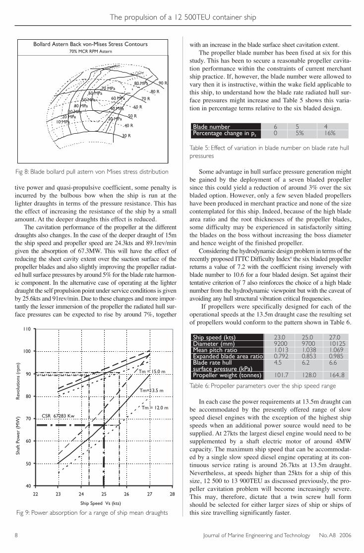
tive power and quasi-propulsive coefficient, some penalty isincurred by the bulbous bow when the ship is run at thelighter draughts in terms of the pressure resistance. This hasthe effect of increasing the resistance of the ship by a smallamount. At the deeper draughts this effect is reduced.
The cavitation performance of the propeller at the differentdraughts also changes. In the case of the deeper draught of 15mthe ship speed and propeller speed are 24.3kts and 89.1rev/mingiven the absorption of 67.3MW. This will have the effect ofreducing the sheet cavity extent over the suction surface of thepropeller blades and also slightly improving the propeller radiat-ed hull surface pressures by around 5% for the blade rate harmon-ic component. In the alternative case of operating at the lighterdraught the self propulsion point under service conditions is givenby 25.6kts and 91rev/min. Due to these changes and more impor-tantly the lesser immersion of the propeller the radiated hull sur-face pressures can be expected to rise by around 7%, together
with an increase in the blade surface sheet cavitation extent.The propeller blade number has been fixed at six for this
study. This has been to secure a reasonable propeller cavita-tion performance within the constraints of current merchantship practice. If, however, the blade number were allowed tovary then it is instructive, within the wake field applicable tothis ship, to understand how the blade rate radiated hull sur-face pressures might increase and Table 5 shows this varia-tion in percentage terms relative to the six bladed design.
Table 5: Effect of variation in blade number on blade rate hullpressures
Some advantage in hull surface pressure generation mightbe gained by the deployment of a seven bladed propellersince this could yield a reduction of around 3% over the sixbladed option. However, only a few seven bladed propellershave been produced in merchant practice and none of the sizecontemplated for this ship. Indeed, because of the high bladearea ratio and the root thicknesses of the propeller blades,some difficulty may be experienced in satisfactorily sittingthe blades on the boss without increasing the boss diameterand hence weight of the finished propeller.
Considering the hydrodynamic design problem in terms of therecently proposed ITTC Difficulty Index6 the six bladed propellerreturns a value of 7.2 with the coefficient rising inversely withblade number to 10.6 for a four bladed design. Set against theirtentative criterion of 7 also reinforces the choice of a high bladenumber from the hydrodynamic viewpoint but with the caveat ofavoiding any hull structural vibration critical frequencies.
If propellers were specifically designed for each of theoperational speeds at the 13.5m draught case the resulting setof propellers would conform to the pattern shown in Table 6.
Table 6: Propeller parameters over the ship speed range
In each case the power requirements at 13.5m draught canbe accommodated by the presently offered range of slowspeed diesel engines with the exception of the highest shipspeeds when an additional power source would need to besupplied. At 27kts the largest diesel engine would need to besupplemented by a shaft electric motor of around 4MWcapacity. The maximum ship speed that can be accommodat-ed by a single slow speed diesel engine operating at its con-tinuous service rating is around 26.7kts at 13.5m draught.Nevertheless, at speeds higher than 25kts for a ship of thissize, 12 500 to 13 900TEU as discussed previously, the pro-peller cavitation problem will become increasingly severe.This may, therefore, dictate that a twin screw hull formshould be selected for either larger sizes of ship or ships ofthis size travelling significantly faster.
Ship speed (kts) 23.0 25.0 27.0Diameter (mm) 9200 9700 10125Mean pitch ratio 1.013 1.038 1.069Expanded blade area ratio 0.792 0.853 0.985Blade rate hull 4.5 6.2 6.6surface pressure (kPa)Propeller weight (tonnes) 101.7 128.0 164..8
Blade number 6 5 4Percentage change in pz 0 5% 16%
The propulsion of a 12 500TEU container ship
Journal of Marine Engineering and Technology No. A8 20068
Bollard Astern Back von-Mises Stress Contours70% MCR RPM Astern
10 MPa20 MPa20 MPa
30 MPa40 MPa
40 MPa
50 MPa60 MPa
60 MPa
70 MPa80 MPa
30 R
40 R
50 R
60 R
70 R
80 R
90 R
Fig 8: Blade bollard pull astern von Mises stress distribution
40
50
60
70
80
90
100
110
22 23 24 25 26 27 28
Ship Speed Vs (kts)
Shaf
t Po
wer
(M
W)
R
evol
utio
ns (
rpm
)
CSR 67283 Kw
Tm = 12.0 m
Tm=13.5 m
Tm = 15.0 m
Fig 9: Power absorption for a range of ship mean draughts
A8 carlton.qxd 12/10/06 3:27 pm Page 8

Comparing the ratio of propulsion efficiencies of the shipat 13.5m draught when propellers specifically designed foreach speed are utilised to the case where a propeller designedfor 25kts is utilised over the speed range, 23 to 27kts, it isseen that an improvement in propulsive efficiency of around2% occurs at the high speed end of the speed range; Table 7.
Table 7: Effects on propulsion efficiency ratio
PROPULSION MACHINERYFor the purposes of this conceptual study the propulsion systemcomprised the elements shown in Table 8 coupled to a slow speedmarine diesel engine. With regard to the slow speed dieselengines, a range of commercially available engines was consid-ered embracing cylinder diameters from 960mm through to1080mm. The maximum continuous rating speed was taken aseither 94rev/min or 102rev/min as appropriate. The shafting sys-tem was equipped with forward and aft stern-tube bearings andfive intermediate plummer bearings supporting the shafting.
Table 8: Shafting system principal dimensions
Although the shafts have diameters in excess of 1m it isconsidered that they are unlikely to present intractable prob-lems during their manufacture provided that the appropriatemeasures are taken during production.
Torsional vibration analysis The torsional vibration characteristics were evaluated for therange of propulsion systems. The overall torsional vibration char-acteristics exhibited similar behaviours in which the II-node res-onance of the system was excited, particularly in the misfiringcase which resulted in high vibratory stresses in the crankshaftexceeding the permissible stress levels for continuous operation.The effect of this torsional behaviour was investigated for the fol-lowing three characteristic 14 cylinder systems. Systems 1 and 2relate to a 980 and 1080mm bore diesel engine while System 3refers to a 960mm bore engine. The torsional natural frequenciesof the three systems are defined in Table 9.
Table 9:Torsional vibration undamped natural frequencies (cpm)
The forced damped torsional response of the systemswas predicted. In all cases under both normal and misfir-
ing conditions the torsional behaviour of the tail and inter-mediate shafts was satisfactory with the shafting arrange-ment defined by Table 8. The crankshaft characteristicswere, however, found to be troublesome in the misfiringconditions and in some engines at the normal firing condi-tion. For the set of systems considered Fig 10 shows a typ-ical set of characteristics under misfiring conditions with-out a damper fitted.
Fig 10a: Propeller shaft characteristics with cylinder 1 misfiring
Fig 10b: Intermediate shaft characteristics with cylinder 1misfiring
Fig 10c: Crankshaft at cylinder 9 with cylinder 1 misfiring
To attenuate this resonance, dampers were tuned todissipate energy at the II-node frequency and, hence,reduce the torsional vibratory peak stresses in the crank-shafts at their critical II-node speeds. The inclusion of atorsional damper into the systems considerably assistedthe suppression of the unwelcome crankshaft torsionalbehaviour. For the same system shown in Fig 10c, themodification of the torsional characteristics by fitting atuned damper to the shafting arrangement, described inTable 8, is shown in Fig 11.
Sys-2, Station 11-12 Cyl 9 Cyl1 misfiring
051015202530354045
0 20 40 60 80 100 120
Shaft speed (rpm)
Tors
iona
l vib
rato
ry 0
,5
rang
e st
ress
(N
/mm
2 ) Cyl 9RuleMCR 94 rpm
Sys-2, Station 21-22 Intermediate shaft 4 Cyl1 misfiring
01020304050607080
0 20 40 60 80 100 120Shaft speed (rpm)
Tors
iona
l vib
rato
ry 0
,5
rang
e st
ress
(N
/mm
2 ) Inter. Shaft 4Rule MCR 94 rpm
Sys-2, Station 22-23 Propeller shaft Cyl1 misfiring
051015202530354045
0 20 40 60 80 100 120Shaft speed (rpm)
Tors
iona
l vib
rato
ry 0
,5
rang
e st
ress
(N
/mm
2 )
Prop. ShaftRule MCR 94 rpm
System I-node II-node III-nodeSystem-1 136.0 649.2 1215.7System-1 + damper 134.0 620.5 1175.1System-2 122.0 585.6 1129.9System-2 + damper 120.7 560.1 1085.0System-3 133.8 602.2 1145.9System-3 + damper 128.7 532.3 1032.4
Shaft speed at MCR (rev/min) 94 102Rule tail-shaft diameter (mm) 1042 1018Rule inter-shaft diameter (mm) 853 834Shaft length to engine flange (m) 70.0 70.0Tail-shaft length (m) 15.5 15.5Intermediate shaft 1 length (m) 13.7 13.7Intermediate shaft 2 length (m) 12.8 12.8Intermediate shaft 3 length (m) 14.0 14.0Intermediate shaft 4 length (m) 14.0 14.0
Ship speed (kts) 23 25 27Propulsion efficiency ratio 1% 0 2%
The propulsion of a 12 500TEU container ship
9No. A8 2006 Journal of Marine Engineering and Technology
A8 carlton.qxd 12/10/06 3:27 pm Page 9

Fig 11: Crankshaft at cylinder 9 with cylinder 1 misfiring with atuned damper fitted
From Fig 11 the torsional stress in the crankshaft is nowjust within the limiting value for the engine under misfiringconditions. However, the general torsional characteristic is ona rising flank and some of the systems examined would leadto the introduction of a barred speed range embracing theoperating speed range.
To explore removing the barred speed range from the nor-mal operating speed range a variational study was undertak-en on the intermediate shaft diameter for another of the
machinery options. This was varied from the values quoted inTable 8 up to a maximum of a 22% increase keeping the shaftlengths constant. Again, considering a synthesis of the first 12orders and a propeller specific damping of 30, it was foundthat a change in intermediate shaft diameter in associationwith a tuned damper was sufficient to control the torsionalcharacteristics to an acceptable level in the operating rangesfor the propeller, intermediate and crank shafts.
Variations in cylinder number, with attendant changes inbrake mean effective cylinder pressure, and firing order were seento have minimal influence on the overall system characteristics.
Lateral vibrationCalculations were performed with both a single and twopoint of support arrangement for the aft stern tube bearingmodels. The former model assumed a single support point athalf the shaft diameter (D/2) into the bearing from the aftend while the latter model assumed two points of support100mm into the bearing from each end. The lateral stiffness-es of the stern tube bearings were changed through a rangeof 50 to 600tonne/mm per support point and a plummerbearing stiffness of 100tonne/mm was assumed for allplummer bearings. The recommended stiffnesses of theengine bearings were used. The sensitivity of lateral vibra-tion natural frequencies to stern tube bearing stiffness was
explored and for the shafting con-figuration designed for 94rev/minFigs 12 and 13 show this sensitivi-ty at blade rate, 6th order, for thesingle and two points of supportmodels respectively.
These figures show that theblade rate critical speeds of the for-ward and reverse whirls of themode-1 resonance were within±20% of the MCR speed of94rev/min. Predicted critical speedsat the 50 to 100tonne/mm point ofcontact lateral stiffness were similarfor the D/2 and the two supportpoint models, but at higher point ofcontact lateral stiffnesses, above150tonne/mm, the two support pointmodel predicted a higher criticalspeed relative to the D/2 model.
Similarly, Figs 14 and 15 showthe sensitivity of the lateral vibrationcritical speeds at twice blade rate tovariations in the stern tube bearingpoint of support lateral stiffness formodels with a single and two pointsof support respectively. Again thesefigures show that at twice blade rate,12th order, critical speeds of the for-ward and reverse whirls of mode-4to mode-6 resonances were withinthe ±20% of the MCR speed of94rev/min at a stern tube bearingpoint of support lateral stiffness of50tonne/mm and above.
Sys-2, Station 12-13 Cyl 9 with Geislinger damper, Cyl 1 misfiring
0
5
10
15
20
25
30
0 20 40 60 80 100 120Shaft speed (rpm)
Tors
iona
l vib
rato
ry 0
,5
rang
e st
ress
(N
/mm
2 )
Cyl 10RuleMCR 94 rpm
The propulsion of a 12 500TEU container ship
Journal of Marine Engineering and Technology No. A8 200610
Shaft Whirling Container Ship, Sys.2 D2 model, 6.0 order
0
20
40
60
80
100
120
140
160
0 100 200 300 400 500 600 700 800 900
Sterntube stiffness (tonne/mm)
Cri
tical
spe
ed (
rpm
)
6.0 order, mode 2-6.0 order, mode 2 6.0 order, mode 1 -6.0 order, mode 1 NOR speed +20% NOR limit -20% NOR Limit
Rigid
Shaft Whirling Container Ship, Sys.2 2PoS model, 6.0 order
0
20
40
60
80
100
120
140
160
0 100 200 300 400 500 600 700 800 900
Sterntube stiffness (tonne/mm)
Cri
tical
spe
ed (
rpm
)
6.0 order, mode 1 -0.6 order, mode 1 6.0 order, mode 2-6.0 order, mode2 NOR Speed NOR Speed +20% NOR Speed -20%
Rigid
Fig 12: Lateral vibration blade rate critical speeds – D/2 model
Fig 13: Lateral vibration blade rate critical speeds – 2PoS model
A8 carlton.qxd 12/10/06 3:27 pm Page 10

Whether these lateral vibration modes could be significantlyexcited by the propeller was examined by a finite element modelusing the two point of support model for the aft stern tube bear-ing with a point of support lateral stiffness of 100tonne/mm. Thepropeller was modelled as a disc with an equivalent total wetpolar moment of inertia of the propeller. Vorus and Parsons’method7 was used to predict the added mass and damping coef-ficients due to the propeller entrained water. The propellerentrained water damping coefficients and the gyroscopic damp-ing are functions of shaft speed and the forced damped responseanalyses were analysed with these coefficients at the MCR shaftspeed since the primary range of interest was MCR shaft speed±20%.
The bearing arrangement for the lateral vibration compu-tation is presented in Table 10 where the bearing location rep-resents the distance from aft end of the shafting system to thepoint of support at the named bearing. ∆L is the distancebetween adjacent bearings.
Table 11 indicates the lateral vibration critical speeds atblade and twice blade rate derived from Campbell diagramsspecific to the 1080mm and 960mm bore engine shaft sys-tems. Clearly, there is a strong similarity between the criticalspeeds as might be expected.
Fig 16 shows the resultant lateral displacement responseof a shafting system at the propeller station under propellerblade rate excitation.
The most significant lateral displacements were at blade rateand located at the propeller for all systems at approximately3.2mm. All other responses at blade rate were below 1mm. Forthe twice blade rate frequency at the mid-span of intermediateshaft 1, some systems attained lateral displacements of up to1.7mm: this was the resonance of vibratory modes 5 and 6. Allother responses at twice blade rate were below 1mm.
The lateral vibration analysis showed that the propeller spanmode gives the largest response and although lateral vibrationnatural frequencies occur within the ±20% MCR speed range, itis considered unlikely that these critical speeds in a detailed
The propulsion of a 12 500TEU container ship
11No. A8 2006 Journal of Marine Engineering and Technology
Shaft Whirling Container Ship, Sys.2 D2 model, 12.0 order
0
50
100
150
200
250
300
0 100 200 300 400 500 600 700 800 900
Sterntube stiffness (tonne/mm)
Cri
tical
spe
ed (
rpm
)
NOR Speed NOR Speed +20% NOR Speed -20% 12.0 order, mode 3-12.0 order, mode 3 12.0 order, mode 4-12.0 order, mode 4 12.0 order, mode 5
-12.0 order, mode 5 12.0 order, mode 6-12.0 order, mode 6 12.0 order, mode 7-12.0 order, mode 7
Rigid
Shaft Whirling Container Ship, Sys.2 2PoS model, 12.0 order
0
50
100
150
200
250
300
0 100 200 300 400 500 600 700 800 900 1000
Sterntube stiffness (tonne/mm)
Cri
tical
spe
ed (
rpm
)
NOR Speed NOR Speed +20% NOR Speed -20% 12.0 order, mode 3-12.0 order, mode 3 12.0 order, mode 4-12.0 order, mode 4 12.0 order, mode 5 -12.0 order, mode 5 12.0 order, mode 6-12.0 order, mode 6 12.0 order, mode 7-12.0 order, mode 7
Rigid
Fig 14: Lateral vibrationtwice blade rate criticalspeeds – D/2 model
Bearings Location (m) ∆L (m)Fwd stern tube 9.9 9.8Plummer bearing 1 19.7 10.52Plummer bearing 2 30.2 9.9Plummer bearing 3 40.2 10.4Plummer bearing 4 50.6 9.8Plummer bearing 5 60.4 10.4Engine bearing 1 70.8
Table 10: Bearing arrangement - locations from aft end ofshafting system
Fig 15: Lateralvibration twice bladerate critical speeds –2PoS model
A8 carlton.qxd 12/10/06 3:27 pm Page 11

design would cause a problem. Moreover, additional minorrearrangement of the bearing locations would most likely furtherattenuate the lateral response in the shafting spans.
Axial vibrationNone of the propulsion systems exhibited any untoward glob-al axial vibration characteristics. However, in a detailed
design some localised problems may be encountered andthese will need to be dealt with as appropriate.
Shaft alignmentIn addition to the engine builder’s requirements, the alignmentcharacteristics of the shafting systems were based on the empiri-cal criterion of the maximum relative slope between the aft sterntube bearing and the shaft being less than 0.0003rad. As previous-ly, in each of the systems two shafting system models were con-sidered: one with a single point of support and the other with atwo point of support model. In the case of the forward stern tubebearing the bearing was assumed to be supported at its mid posi-tion.
The prescribed alignment, Fig 17, was defined for the hotstatic condition. The propeller was assumed to be fullyimmersed and typical thermal rises ranged from 0.29 and0.39mm depending upon the choice of prime mover. The verti-cal shaft deflections shown here for one of the prescribed align-
ments of the set of shafting systemsmay be considered as representativewith only small but, nevertheless,important differences occurringbetween them.
Fig 18 shows the equivalentbearing loads for the system towhich Fig 17 refers. All bearingload limits were satisfied: theplummer bearing maximum spe-cific loads were 10bar, as specifiedby the manufacturer, and the sterntube maximum specific load wasat 8bar for, in this case, a whitemetal bearing. Alternatively, a sys-tem could be configured for a non-metallic stern bearing arrange-ment. The data in this case, Figs17 and 18, is presented for the hotand cold static cases where the for-mer is presented for the D/2 andthe two point of support aft sterntube model. All systems requiredslope boring of the aft stern tubewith the magnitude of the shaftangular deflection under staticconditions lying in the range0.000388 < ε < 0.000431rad,depending upon the particular sys-tem.
In the case of the main enginesthe load limits were specified by theengine manufacturers. The limits of
engine flange shear force and bending moment for either the hotand cold static conditions or, alternatively, the minimum andmaximum load on the aft engine bearings 1 to 3 were satisfied.Nevertheless, since these are very long engines care needs to beexercised in the set up of the engine and to ensure that the foun-dations provide adequate support throughout the range of theship’s operating conditions.
Consequently, the static alignment analysis shows thatadequate alignment margins can be achieved for a ship of this
The propulsion of a 12 500TEU container ship
Journal of Marine Engineering and Technology No. A8 200612
Critical speeds (rev/min)Engine Bore 1080mm 960mm Blade rateMode-1 68.1 73.8Mode-2 77.1 82.6Twice blade rateMode-1 34.1 36.9Mode-2 38.5 41.3Mode-3 82.6 76.8Mode-4 82.6 76.8Mode-5 85.8 85.1Mode-6 85.8 85.1Mode-7 91.6 92.0Mode-8 92.9 92.0Mode-9 94.8 94.2Mode-10 98.4 99.7Mode-11 103.9 100.0Mode-12 105.7 102.0Mode-13 172.5 120.1
Table 11: Lateral vibration critical speeds of shafting systemswith stiffness of 100tonne/mm
0.00E+00
5.00E-04
1.00E-03
1.50E-03
2.00E-03
2.50E-03
3.00E-03
3.50E-03
4.00E-03
0 20 40 60 80 100 120 140
Shaft speed (rpm)
Dis
plac
emen
t (m
)
Sys2aSys2bMCR 94rpm +/-20%Sys3MCR 102rpm +/-20%
System 3
-10
-8
-6
-4
-2
0
2
0 10000 20000 30000 40000 50000 60000 70000 80000 90000
Shaft length (mm)
Vert
ical
def
lect
ion
(mm
)
Sys3Bearings
Fig 16: Lateral displacement at the propeller station and blade rate order
Fig 17: A typical hot static prescribed alignment condition
A8 carlton.qxd 12/10/06 3:27 pm Page 12

size for all of the systems examined. Given that the propeller will be of the keyless type and that
it will have a shaft taper sufficient to enable an acceptable fit-ting procedure to be formulated which will allow the designedcontact stresses to be achieved, then the propeller dry weight forthe 12 500TEU ship will be of the order of 128t. Such a finishedpropeller weight will be within the casting capabilities of theprincipal large propeller manufacturers. Nevertheless, the pro-peller weight is significant when considered against contempo-rary propellers although not necessarily by the standards consid-ered some years ago when contemplating the propulsion of aone million tonne tanker.
Options to lighten the propeller or components of it are poten-tially possible either through the use of the built-up concept or bythe use of carbon fibre laid-up blades. In the former case somedifficulty may be experienced with the propeller boss design: par-ticularly in relation to fitting a high number of blades on to the
boss and also in controlling cavitationdevelopment in the root region. In thealternative case of carbon fibre blades,such blades would be constructed froma predetermined sequence of linear andbi-directional weaves based on thenature of the blade chordal and radialloading distributions in order to achievethe required strength and radial and tor-sional flexibility. With this type of bladethere is also the added potential abilityto utilise the blade flexure so as toachieve an added control over the cavi-tation performance over the blades. Itwould be reasonable to expect the drypropeller weight for such a design toreduce by some 50% and clearly thiswould ease the stern tube alignmentproblem. However, this technology,which has been relatively successful insmall ship applications, would repre-sent a significant extrapolation of cur-rent service experience.
Shaft dynamic behaviourThe operation of ships in a seaway orwhen undertaking turning or changesof speed manoeuvres causes a seriesof spatial and temporal changes tooccur in the velocity field presentedto the propeller. These changes occurin varying degrees to the flow veloc-ities in each of the three Cartesiandirections of flow and generate addi-tional components of loading overthe blades. These loadings, in-turn,have to be reacted by the bearingsthrough the influence of the lubricantfilms. In the case of acceleratingmanoeuvres in calm water, in thiscase for a nominal 4000TEU ship,the measured loci of the shaft dis-placement measured just aft of the oil
seal are shown in Fig 19. From this figure it can be seen thatthe movement of the shaft increases both in its orbit size aswell as eccentricity during an increase in speed from46.9rev/min to 87rev/min. The primary reason for the eccen-tricity in the higher speed ranges is due to the in-plane wakefield components.
In the alternative case of turning manoeuvres then a moreextreme set of shaft orbit excursions can be anticipated. Fig 20shows, again for a smaller container ship, a series of port andstarboard 10deg rudder angle turning manoeuvres undertakenwhen at full speed with a clockwise rotating shaft. The figureshows the envelopes of a set of instantaneous positions of theshaft, measured outboard of the stern seal and recorded over aperiod of two minutes during the turning manoeuvres. It isclearly seen that for the turns to port the propeller shaft is forcedupwards and towards the 11 o’clock position, when looking for-ward, at the start of the manoeuvre. Then as the manoeuvre
The propulsion of a 12 500TEU container ship
13No. A8 2006 Journal of Marine Engineering and Technology
Bearing LoadsSys3
0
50000
100000
150000
200000
250000
0 10000 20000 30000 40000 50000 60000 70000 80000
Shaft distance (mm)
Bear
ing
load
(kg
)
Hot Static 2PoSHot Static D2Cold Staic D2Max. LoadMin. Load
Fig 18:Typical prescribed alignment static bearing loads
Fig 19: Loci of shaft displacement during an accelerating manoeuvre
A8 carlton.qxd 12/10/06 3:27 pm Page 13

develops the shaft then starts to fall back towards a more centrallocation. In contrast, during the starboard manoeuvre the shaftis forced to between a 3 o’clock and 6 o’clock position; startingclose to the former location and as the manoeuvre progressesmoving towards the latter position.
For larger rudder angles at high speed these tendenciesbecame more pronounced: when undertaking port turns theshaft endeavoured to take up more extreme positions whilefor starboard turns the position in the bearing can traverse thewhole of the region from 3 o’clock to 9 o’clock. It is alsonoticeable that greater levels of positional instability wereseen at very high rudder angles. Consequently, this behaviourhas profound implications for the positioning of the lubricantwash-ways in the bearings since if the shaft lands on the edgeof a wash-way during such a manoeuvre the oil film is likelyto be broken and the lubrication condition compromised.
These shafting behaviours are characteristic of single screwships and a similar behaviour in terms of the qualitative charac-teristics of the shaft motion might be expected for a 12 500TEUship. In quantitative terms, the absolute magnitudes of the shaftmotions will vary depending upon the weights of the shaft andpropeller, the forces and moments developed from the propellerworking in the actual wake field and the design of the ship’sstern aperture in relation to the restrictions it places on thedevelopment of the transient aspects of the wake field.
RUDDER HYDRODYNAMICSWhen high power and speed are required careful attentionto the rudder design is essential if a continuing series ofcavitation erosion problems are to be avoided.
Furthermore, cavitation erosion also facilitates severalforms of corrosion attack which, in addition to the ero-sion, tends to compound the operational maintenanceproblems. In the case of large container ships attention tothe rudder profile and detail of the design is paramount.
Because the rudder operates in a combination of thehelicoidal flow field produced by the propeller and theship’s boundary layer, the incident flow presented to therudder has a strong rotational component as evidenced bythe behaviour of the propeller blade tip vortices.Additionally, the rudder tends to distort the flow fieldsuch that the slipstream generated by the propeller oftenexpands up the leading edge of the rudder by a smallamount.
While the presence of cavitation does not necessarilyimply erosion, it is true that many rudders fitted to largecontainer ships experience erosion. Frequently, attemptshave been made to attenuate these erosive effects of cavi-tation by the fitting of stainless steel or stellite armour tothe rudder and horn: particularly, in the leading edgeregions but also on other parts of the rudder. Suchattempts, however, have often met with only partial suc-cess and have required continuous maintenance during theservice life of the ship. There is, nevertheless, some evi-dence to suggest that more compliant materials may beable to withstand the micro-jet impingement of cavitationattack, at least in the more mild cases of erosion attack.
Figs 21 to 23 show the local cavitation number overthe surface of a large container ship rudder for a range ofrudder angles that would normally be associated with anauto-pilot range of movement. In this context the localcavitation number (σ) is defined as being the ratio of thelocal static pressure head divided by 1/2 ρ v2, where ρ is thedensity of sea water and v is the velocity close to the rud-der surface. These results were derived from a ReynoldsAveraged Navier-Stokes computational fluid dynamicsstudy in which the propeller inflow was modelled for thecontinuous service rating. These results, through the smallbut extremely important changes in local cavitation num-ber and their consequences for erosion, underline theimportance of studying at the rudder design stage therange of likely auto-pilot angles that will be encounteredin service. Such a study can either be done in a large scalecavitation tunnel or with the aid of computational fluiddynamics studies such as these.
To achieve an acceptable solution for high poweredships a careful design strategy comprising elements ofcomputation and model testing requires implementation.Such a strategy might involve the measurement of therudder incident flow field generated by the propeller andthe ship’s boundary layer, recognising that this latter flowfield component will require some modification frommodel scale values due to the significant scale effectspresent on a large container ship. Having defined thisinflow field a first iteration for the rudder geometrydesign can then be produced which may suggest thedesirability of a contoured leading edge, in contrast to thenormal straight line leading edge, in order to permit thegreatest cavitation free incidence ranges to be obtainedfor the components of the rudder. Following this defini-
The propulsion of a 12 500TEU container ship
Journal of Marine Engineering and Technology No. A8 200614
Fig 20: Envelopes of shaft positions during turning manoeuvres
A8 carlton.qxd 12/10/06 3:27 pm Page 14

tion, large scale model cavitation tests should then becarried out to estimate the full scale characteristics of thedesign, both in overall terms as well as in the detailedbehaviour of the design around the pintle housings andthe interfaces between the rudder and horn. Within thistesting phase it is important to carefully evaluate theinfluence that the normal range of auto-pilot rudderangles has on the cavitation dynamics since these angularvariations, for the larger container ship and other highspeed ship designs, will strongly influence the erosionpotential of the design. Furthermore, in order to furtherassess this potential a paint erosion technique might forman integral part of the testing programme; nevertheless,the reliability of this technique for rudder erosion predic-tion is not yet as good as similar procedures for propellerblades.8 Following a model testing phase a second itera-tion of the design can be made in which detailed geomet-ric changes can be introduced in the knowledge of theindividual cavitation bucket assessments of the horn, pin-tle and blade regions of the rudder. Depending on theextent of the changes required a further model test mayalso be desirable.
In the case of the gap interfaces between the horn andblade, as seen in Figs 24 and 25, very careful attention tothese details both at the design and rudder fabricationstages are necessary: the latter aspect to ensure that thedesign intent is achieved because design tolerances aresmall in these severe flow conditions. Such a considera-tion will normally result in a unique specification for thedesign for each ship and this may include the incorpora-tion of scissor and deflector plates in order to afford pro-tection from erosion in or near gap regions, the adviseduse of profile curvature and, on occasions, deployment ofvortex generators. Within this context, large scale modelcavitation tests, centring particularly on the mid-region ofthe rudder so as to minimise scale effects, have beenfound to be a particularly valuable aid to design.
An alternative to the conventional rudder horn-bladeconfiguration is the use of the variable geometry spaderudder concept. This design option allows, in a mean flowsense, for the rotational characteristic of the incident flowfrom the propeller. Furthermore, for these types of rud-ders computational fluid dynamic studies have showngood correlation between the predicted actuating torques
The propulsion of a 12 500TEU container ship
15No. A8 2006 Journal of Marine Engineering and Technology
Fig 21: Local cavitation number over the surface of a semi-balanced large container ship rudder at 0deg helm
Fig 22: Local cavitation number over the surface of a semi-balanced large container ship rudder at 5deg port helm
A8 carlton.qxd 12/10/06 3:27 pm Page 15

and bearing bending moments and side forces with theresults of model tests.
CONCLUDING REMARKSThis concept study has shown that a 12 500TEU contain-er ship, defined using high cube containers, propulsion at25kts and with a 15% sea margin is possible using a sin-gle screw concept and currently available slow speeddiesel engines. To extend the ship speed beyond 26ktstowards 27kts, then the current range of diesel engineswould need to be augmented by an electric motor and thepropeller cavitation problems would be considerable.Indeed, for these higher speeds a twin screw variant of thedesign would probably need to be employed. It has beenshown that a minimum of six blades, moderate skew anda judicious use of rake are essential for the single screwpropulsion concept.
With regard to the machinery selection it has been shownby a series of parametric studies that systems using existingtechnology and capabilities are able to be designed to providethe desired propulsion solution.
The rudder design for these large ships needs to be
undertaken with care if poor results are to be avoided.Such a procedure would need to embrace significantmodel testing at the largest scale possible and over thenormal auto-pilot range of angles as well as being supple-mented by computational fluid dynamics studies. Sadly, atthis time, erosion prediction methods for rudders are intheir infancy.
ACKNOWLEDGEMENTSThe author wishes to thank the Committee of Lloyd’sRegister for permission to publish this paper. In additiongrateful thanks are also due to Dr K Banisoleiman, Mr ABoorsma, Dr D Radosavljevic and Mr D Tozer for theirvaluable contributions and advice on various parts of thework.
REFERENCES1. Tozer D and Penfold A. Ultra-Large Container Ships
(ULCS): Designing to the limit of current and projected ter-minal infrastructure capabilities. Trans LRTA, Paper No.5,Session 2001-2002.
2. Carlton JS. The Propulsion of Large Container Ships:
The propulsion of a 12 500TEU container ship
Journal of Marine Engineering and Technology No. A8 200616
Fig 23: Local cavitation number over the surface of a semi-balanced large container ship rudder at 5deg starboard helm
Fig 24: Port pintle velocity distribution during a 5deg turn tostarboard
Fig 25: Starboard pintle velocity distribution during a 5degturn to port
A8 carlton.qxd 12/10/06 3:27 pm Page 16

A Note on the Propulsion Options. 2001 Int. Colloquium onNav. Arch. & Ocean Eng. Pusan National University, 2001.
3. Tozer D. Design Challenges of Large Container Ships.Boxship 2005, Sept. 2005, Hamburg.
4. Guldhammer and Harvald. Ship Resistance – Effect ofForm and Principal Dimensions. Akademisk Forlag,Copenhagen. 1974.
5. Carlton JS. Marine Propeller Blade Stresses. Trans.
I.Mar.E., 1984.6. Report of the Propulsion Committee, 23rd ITTC, 2002.7. Parsons MG and Vorus WS. Added Mass and Damping
Estimates for Vibrating Propellers. Propellers’ 81 Symp.Trans. SNAME, 1981.
8. Guidelines for the Design of Propellers and Rudderswith Respect to Cavitation Erosion. EROCAV Project GRD1-2000-25089.
The propulsion of a 12 500TEU container ship
17No. A8 2006 Journal of Marine Engineering and Technology
A8 carlton.qxd 12/10/06 3:27 pm Page 17