373 series coating thickness testers le-373/lh · pdf file373 series coating thickness testers...
TRANSCRIPT

373 Series Coating Thickness TestersLE-373/LH-373/LZ-373
Operating Manual

Coating Thickness Tester Safety Precautions
● Be sure to carefully follow all safety precautions. Carefully read operating manual.
● Do not use the unit if it is not functioning property. Immediately contact our service representative if the unit malfunctions or does not operate properly.
● Measuring of Warning Indications. The symbols indicated below are used in the operating manual and on the unit itself in order to prevent accidents due to misuse of
the product. These symbols have the following meanings:
This symbol indicates information important for the understand in order to safety operate the product.Caution

1. Measuring Principles and Characteristics ................................... 4
2. Instrument view .......................................................................... 6
3. Display and Keypad Functions ................................................... 8
4. Specifications ............................................................................. 9
5. Preparations for Operation ......................................................... 10
6. Operation Method....................................................................... 11
7. Settings ...................................................................................... 12
8. Calibration .................................................................................. 24
9. Battery Replacement .................................................................. 31
10. Data output format ...................................................................... 32
11. Troubleshooting .......................................................................... 33
12. Notes for Measuring and Handling ............................................. 34
Contents

4
•The model LE-373electromagnetic coating thickness tester is designed tomeasure the thickness of non-magneticcoatings such as paint or plating on magnetic metal substrates (iron or steel).
•ThemodelLH-373EddyCurrentcoatingthicknesstester isdesignedtomeasurethethicknessof insulatingcoatingssuchasalumiteorpaintonnon-magneticmetalsubstrates(suchasaluminumorcopper,etc.).
•ThemodelLZ-373dual-typecoatingthicknesstester isdesignedtomeasurethethicknessofeithernon-magneticorinsulatingcoatingsoneithermagneticornon-magneticmetalsubstrates.
•ABeryllium-coppercalibrationfoil isrequiredinordertomeasurethethicknessofplatingcoatings.
1. Measuring Principles and Characteristics
<Applicable Coatings>
Model LZ-373
Ap
plicab
le Co
ating
s
LE-373 LH-373Paint Plastic Paint AlumiteLacquer Resin Rubber PlasticRubber Enamel Enamel LacquerLining Zinc Resin OtherChrome TinCopper AluminumOther
Substrate Iron Steel Aluminum, Copper, Brass, etc.

5
•LH-373
( E d d y C u r r e n t m e a s u r e m e n t m e t h o d : Fo r measuring the thickness of insulating coatings on non-magnetic metal substrates)
Aneddycurrent isproduced in thesurfaceofametalwhenacoil throughwhichacurrentof fixed frequencyis brought near the metal. This eddy current and the voltage at the ends of the coil change in proportion to the distance between the coil and the metal surface. This change can be determined from the current value and thisisusedtocalculatethethicknessofthecoating.
•LE-373
(Electromagnetic measurement method : For measuring the thickness of non-magnetic coatings on magnetic metal substrates)
When an alternating current electromagnet is brought near iron (or other magnetic metal) the number of magnetic flux lines passing through the coil changes in proportion to the distance, thereby causing a changein the voltage at the ends of the coil. This change in voltage is determined from the current value and this is usedtocomputethethicknessofthecoating.
•LZ-373(DualElectromagneticandEddyCurrentType)
ThemodelLZ-373 isadual typecoating thickness testerwhich featuresboth theelectromagneticandEddyCurrentmeasurement methods.
Induction coil
Insulating CoatingNon-MagneticMetal
ThicknessD
High-FrequencyPower Supply
Current Change i
Low-FrequencyPower Supply
Non-MagneticCoatingIron•Steel
ThicknessD
Electromagneticcoil
Current Change i
i

6
Rear Panel
Probe
Top View
Fe Probe (Black Cable)Electromagnetic “LEP-J”
Probe ConnectorDust Capprinter & ComputerOut put Connector
Display
Keyboard Battery Box
Connector
Measurement Part
Connector
Measurement PartNFe Probe (Gray Cable)Eddy Current “LHP-J”
2. Instrument view
Main part
Front Panel

7
Accessories
IronSubstrate(FE-373) AluminumSubstrate(NFE-373) StandardCalibrationFoils ProbeAdaptor (ForLE-373,LZ-373) (ForLH-373,LZ-373) (LE-373,LZ-373:6pcs/LH-373:5pcs)
BatteriessizeAA(4pcs) CarryingCase OperatingManual CalibrationFoilcase
Optional Accessories
PrinterVZ-380(with printer
cableVZC-60)
Personal computer cable
VZC-53
RS-232C-USBconverter
Measuring Stand LW-990
DataLoggerSoftware “LDL-03”
Calibration Foils(thicknessesotherthan
those supplied)

8
Date&TimeorLot&Datanumbers(see p. 19)
Measurement Value
MeasurementUnits(seep.21)
Settings (see p. 12)
* Refer to the page indicated in parentheses for the functions or purpose of each pattern.
Battery alarm (see p. 31)
Measuring method (FE:ElectromagneticorNFe:Eddy-Current)
Calibration (see p. 24)
3.DisplayandKeypadFunctions
OperationKeys Functions
Power Key
Turns the power on and off.
Scrolling Key
Usedtomovetothedesireditemonthe screen.
OperationKeys Functions
EnterKeyConfirms the item or value displayed on the screen.
Numeric Key 〜
Usedtoenternumericvalues.
Delete KeyUsedtodeleteanenterednumericvalue.

9
Model / Measuring Method
LZ-373 / Electromagnetic and Eddy-current
LE-373 / Electromagnetic LH-373 / Eddy-current
Probe Type LEP-J(Fe) LHP-J(NFe)
Applications Non-magneticcoatingsonmagneticmetal(iron,steel) Insulatingcoatingsonnon-magneticmetal(non-iron)
Measurable Range 0 to 2500μm or 99.0 mils 0 to 1200μm or 47.0 mils
Measuring Accuracy Under50μm:±1μm,50μmtounder1000μm:±2%,1000μmandover:±3%
Resolution Under100μm:0.1μm,100μmandover:1μm
DataMemory Approx.39,000points
Application Memory 100(LZ-373:50typeseachofelectromagneticandeddy-current)
DisplayMethod Digital(LCDwithbacklight,smallestdisplayunit:0.1μm)
External Output PC(USBorRS-232C),printer(RS-232C)
Power Supply 1.5Valkalinebatteries(sizeAA)x4
Power Consumption 80mW(withbacklightoff)
Battery Life 100hours(continuoususewithbacklightoff)
Operating ambient temp. 0 to 40 ℃
Functions 16,varioussettings
Dimensions&Weight Mainunit:75(W)x145(D)x31(H)mm,0.34kg
Accessories Ironsubstrate(FE-373),aluminumsubstrate(NFE-373),calibrationfoilset,probeadapter,carryingcase,1.5Vbatteries(sizeAAalkaline)x4,operatingmanual
OptionsCalibrationfoils(otherthanthefurnishedset),measuringstandLW-990,printerVZ-380(withprintercableVZC-60),PersonalcomputercableVZC-53,RS-232C-USBconverter,datamanagementsoftware“DataloggersoftwareLDL-03”
4. Specifications

10
OPEN
(1) Insert the batteriesThe battery cover is opened by sliding the battery cover on the rear of the case in the direction indicated by the arrowhead mark("∆").Insert4sizeAAalkalinebatteriesintothebatterycompartmentas indicatedby thepicture in the compartment.Take care toalign the positive and negative ends of the batteries correctly.
(2) Selecting and Connecting the probe (LZ-373)Select a probe appropriate to the type of sample to be measured with switching the main unit off.
(LE-373•LZ-373)Non-magneticcoatingonmagneticmetalsubstrates:Electromagnetictypeprobe Fe probe (Black)<LEP-J>
(LH-373•LZ-373)Insulatingcoatingsonnon-magneticmetalsubstrates:Eddycurrenttypeprobe NFe probe (Gray)<LHP-J>
•Theprobecanbeeasilyconnectedtothemainunitbyturningalittlewhilesoftlypressingitintotheprobesocketonclockwiseof the main unit.
•Whenremovingtheprobefromthemainunit,alwaysbesuretogrip,themetalfittingattheendoftheprobecordconnectedtothe main unit. Note that the probe can not be disconnected by pullingontheblackportionofthecord.
Slide to open
Loadbatteriesintothemainunit
Connecting the probe
5. Preparations for Operation

11
(1) Probe selection and attachment Check that the power supply is off and then attacheitherthe LEP-Jor LHP-Jprobeaccording to the substrate to bemeasured (see p. 10).
(2) Power ON PressthePowerkey.
(3) Calibration Checkwhether themeasurement target hasalreadybeencalibrated. If not, then perform calibration and register the calibration curve (application) (see p.24).
(4) Measurement Theprobes are of the "one-point contact constant-pressuretype,"wherebyaconstantloadisappliedtothetipoftheprobe.As shown in the figure on the right, hold thepart near themeasuring part and lower the probe rapidly so that the probe is at a right angle in relation to the measurement surface. To prepareforthenextmeasurement,liftofftheprobetiponceatleast 10 mm from the measurement surface.
Whenmeasuringacylindricalobjector continuouslymeasuring a flat surface, the use of a probe adapter allows stable measurement.
Probe usage method Probe adapter usage method
Attachtheprobeadapter to the tip of the probe and secure it by tightening the screw.
Rapidly lower the probe onto the measurement surface.
DisplayExample(ElectromagneticMeasurementMode)
Measurement enabled state Measurement result
Measurement
6. Operation Method

12
● The following 16 functions can be selected on SET mode.
1 Application (P.14)
2 Substrate Cal. (P.14)
3 Delete Data (P.15)
4 Data Memory (P.16)
5 Limits (P.17)
6 Statistics (P.18)
7 Disp.Property (P.19)
8 Date/Time (P.19)
9 AutoOffTime (P.20)
0 Brightness (P.20)
! LightingTime (P.21)
@ Unit (P.21)
# Data Output (P.22)
$ LotSplitting (P.22)
% Hold/Continues (P.23)
^ Maintenance (P.23)
& Esc
* Refer to the page indicated in parentheses for the functions or purpose of each pattern.
7. Setting

13
<DisplayExample>● Procedure of Various Functions
(1)Tosetvariousfunction,selectSET by pressing key.
Press keyandthevariousfunctionswillbedisplayed.
(2)Selectafunctionyourequiredby or keys,andpress key.
Incaseofrightdiagram,Application function is selected.
* Only 4 functions are displayed in the manner shown on the right, but the other functions will be also displayable in the 1-& order indicated p.12 by scrolling.
* There are 16 various functions that can be set. (& Esc is excluded)
* Once a function is set, it will remain in memory until changed even if the power is switched off.

14
1 Application LE-373&LH-373:Atotalof100applications(calibrationcurves) can be set. LZ-373 :A totalof 100applications , consisting ofapplication numbers0 to49 for theelectromagnetictypemeasurementand applicationnumbers50 to99for the eddy-current type measurement, can be set.
・・・・
(1) Perform steps (1) and (2) on p.13.
(2)PresstheDelkey,andafterthedisplayed application number barhasbeendeleted,enterthedesired application number. Then press the Enter key toapply your selection and return to the measurement screen.
* Once an application number has been set, it is saved even after the power is switched off until the next time it is changed.
* LZ-373 : The selectable application numberrangeis0to49forFeand50to99forNFe.Ifanout-of-rangenumberisselected, an error is displayed.
(3) To leave the application number unchanged,selectEsc with the →key,andthenpresstheEnterkey. The screen will changebac k to t he measurementscreen without changing the application number.
2 Substrate Cal. Once substrate calibration has been done, it is not necessary to perform calibration for subsequent measurements.However, if theobject tobemeasuredis changed or the probe is replaced, etc., calibration must be performed again. * A substrate refers to a piece made with the same material and shape as the pieces to be measured, but not covered with coating (plating or paint).
(1) Perform steps (1) and (2) on p.13.
(2) Point the probe in the air and presstheEnterkey.Measurement is per formed automatically 7 times.

15
・・・・
3DeleteDataThemeasurementdatainDataMemorycanbedeleted.
(1) Perform steps (1) and (2) on p.13.
(2)Press theDel key, andafterthe displayed data number has disappeared, enter thedatanumber to be deleted from the numerickeypad.
Then press the Enter key toexecute the deletion and then return to the measurement screen.
(3) To delete all the data in the memory, press the→ key toselect All.
PresstheEnterkeytodeleteallthe data and then return to the measurement screen.
(4)Tonot delete data, selectEsc by pressing the ← or → key.Then press the Enter key toreturn to the measurement s c r e e n w i t h o u t d e l e t i n g anything.
(3)PresstheEnterkey.
(4) The prov ided subs t ra te i s measured 7 times.
(5)Press theEnterkey toexecutecalibration and then return to the measurement screen.

16
4DataMemorySet whether or not to save the measurement data to the data memory.
(1) Perform steps (1) and (2) on p.13.
(2)Tosavethemeasurementdata,select Store by pressing the ↑ or ↓key.
ThenpresstheEnterkeytosetthe data to memory and then return to the measurement screen.
* Af ter this set t ing is done, the measurement data is saved in the internal memory.
* To execute Statistics (see p. 18), prior to executing measurement, set Store. If this setting is done after measurement, or if Null is set, the measurement data is not saved to internal memory until Statistics is executed.
(3)PresstheDelkeytodeletetherecent measurement data.
(4) To c a n c e l s av i n g t o d a t a memory,selectNull by pressing the ↑ or ↓key.
Then press the Enter key tocancel the setting and return to the measurement screen.
(5)Toleavethesettingunchanged,select Esc by pressing the ↓ key, and then press theEn te r key to re tu rn to t hemeasurement screen without changing the setting.
(6) I f t h e r e m a i n i n g m e m o r y capacitybecomes insufficient,t he sc reen on the r i gh t i s displayed. To delete all the data inthememory,selectAllClear .
Then press the Enter key toexecute deletion and return to the measurement screen.
To e xe c u t e D a t a O u t p u t ,etc., select Skip . Press the Ente r key to re tu rn to t hemeasurement screen without changing the setting.

17
5 Limits This function memorizes the upper and lower limits and emits a beep to notify the operator when the measurement value exceeds the set upper limit or falls below the lower limit.
(1) Perform steps (1) and (2) on p.13.
(2)To set the l imi ts, move thecursor to the upper l imit or lower limit with the ← and → keys, and then press the Delkey to clear the entered value.Then newly enter the desired valuefromthenumerickeypad.
Move the cursor to theon/offselection column with the → key, and thenmove the cursorto on with the ↑ and ↓keys.
Press theEnter key to set theentered value and return to the measurement screen.
(3)To cancel the limits, selectoff for both the upper limit and the lower limit by pressing the ←,→,↑, and↓ keys, and thenpress theEnter key to cancelthese settings and return to the measurement screen.
(4) T o l e a v e t h e s e t t i n g s unchanged, se lec t Esc by pressing the ← or →key.Thenpress the Enter key to returnto the measurement screen without changing the settings.

18
6 Statistics This function displays the maximum value, minimum value, calibration deviation, and the average value and sets the data range to be calculated. To exe cu te S t a t is t i c s , f i r s t se t S to r e p r io r to measurement (see p. 16).
(1) Perform steps (1) and (2) on p.13.
(2) Move the cursor to the data range numbers with the ↑ and ↓keys,andthenpresstheDelkeytocleartheenteredvalues.Then enter the new lower limit valuefromthenumerickeypad.Next,withthe→keymovethecursor to the blank upper limitfield, andenter theupper limitfromthenumerickeypad.
(3)Press theEnter key to displaythe number of data in the set range.
(4)Next, press the Enter key todisplay the various statistics.
Press theEnter keyagain toreturn to the measurement screen or the data range setting screen.
* If Lot Splitting has been set (see p. 22), the lot number is automatically incremented until Statistics is executed.
(5)TonotexecuteStatistics,pressthe →keytoselectEsc. Then press the Enter key to returnto the measurement screen without executing Statistics.

19
[Date/Time]
[Lot/DataNo.]
7Disp.PropertyThemeasurementscreencanbeselected from [Date/Time]and[Lot/DataNo.].
(1) Perform steps (1) and (2) on p.13.
(2)Select either [Date /Time] or[Lot/Data No.] by pressing the↑ or ↓key.
Then press the Enter key toapply the setting and return to the measurement screen.
(3)Toleavethesettingunchanged,select Esc by pressing the ↓ key. Then press theEnter keyto return to the measurement screen without changing the setting.
8Date/TimeTheDate/Timecanbeset.
(1) Perform steps (1) and (2) on p.13.
(2)A d j u s t t h e D a t e / T i m e b ypressing the ← and → keysor the ↑ and ↓ keys.Thenpress theEnter key to applythe settings and return to the measurement screen.
(3) T o l e a v e t h e s e t t i n g s unchanged, se lec t Esc by pressing the ← or →key.Thenpress the Enter key to returnto the measurement screen without changing the settings.

20
9 Auto Off Time The time until the power is automatically switched off in the absence of measurement or key operation can be set(5minutes,10minutes,20minutes,orContinuous).
0 Brightness Thebrightnessof thebacklightcanbeset (Off,Dark,Medium, Lightish), allowing the operator to set the optimum brightness for easy viewing according to the ambient brightness.
(1) Perform steps (1) and (2) on p.13.
(2) Select the time until the power is automatically switched off (5 minutes, 10 minutes, 20minutes), or Continuous by pressing the ↑ or ↓ key.Thenpress the Enter key to applythe setting and return to the measurement screen.
(3)Toleavethesettingunchanged,select Esc by pressing the ↓ key. Then press theEnter keyto return to the measurement screen without changing the setting.
(1) Perform steps (1) and (2) on p.13.
(2) Select the level of brightness by pressing the ↑ or ↓ key.Then press the Enter key toapply the setting and return to the measurement screen.
* Setting the backlight to operate great ly increases the bat ter y c o n s u m p t i o n a n d d e c r e a s e s the bat tery l i fe. I t is therefore recommended to set the Lighting Time (see p. 21).
(3)Toleavethesettingunchanged,select Esc by pressing the ↓ key.Then press theEnter keyto return to the measurement screen without changing the setting.

21
! Lighting Time Thelightingtimeforthebacklightcanbesetto5s,10s,or20s.*If"Off"hasbeensetforBrightness(seep.20),thissettingneed not be done.
(1) Perform steps (1) and (2) on p.13.
(2) Selec t the l ight ing t ime by pressing the ↑ or ↓key.Thenpress theEnter key to applythe setting and return to the measurement screen.
(3)Toleavethesettingunchanged,select Esc by pressing the ↓ key.Then press theEnter keyto return to the measurement screen without changing the setting.
@ Unit The display unit (μm, mils) for measurement values can be set.
(1) Perform steps (1) and (2) on p.13.
(2) Se lec t t he d i sp lay un i t by pressing the ↑ or ↓key.Thenpress theEnter key to applythe setting and return to the measurement screen.
(3)Toleavethesettingunchanged,select Esc by pressing the ↓ key.Then press theEnter keyto return to the measurement screen without changing the setting.

22
#DataOutputThe measured data can be output to a personal computer or a printer by connecting the optional cable or printer.
$ Lot Splitting Lot numbers can be automatically incremented as Statistics are executed.
(1) Perform steps (1) and (2) on p.13.
(2) Select the data output method by pressing the ↑ or ↓ key.Then press the Enter key toapply the setting and return to the measurement screen.
(3)Toleavethesettingunchanged,select Esc by pressing the ↓ key.Then press the Enter keyto return to the measurement screen without changing the setting.
Real-time → The data is output simultaneously with measurement. If the settings are changed or Statistics is executed, the new settings or calculation results will be output.
Null →Disablestheaboveoutput.
AllData → All the data in the memory, setting changes, results from Statistics execution, and data deletions are output.
(1) Perform steps (1) and (2) on p.13.
(2) S e l e c t A u t o p a r t i t i o n b y pressing the ↑ or ↓key.Thenpress theEnter key to applythe setting and return to the measurement screen.
* If Auto partition is set, the lot number is automatically incremented at each Statistics execution.
(3) To deactivate the lot splitting function,selectOff by pressing the ↑ or ↓ key.Thenpressthe Enter key to app ly thenew setting and return to the measurement screen.
(4)Toleavethesettingunchanged,select Escby pressing the ↓ key.Then press theEnter keyto return to the measurement screen without changing the setting.

23
% Hold/ContinuesTwo measurement modes are available, "Hold" whereby the measurement value is displayed statically (fixed value), and "Continues" whereby the measurement value is displayed dynamically (changing value).
^ Maintenance The Maintenance mode is used for repa i r and adjustment.Itisnotusedfordailyoperation.
(1) Perform steps (1) and (2) on p.13.
(2) Select the measurement mode by pressing the ↑ or ↓ key.Then press the Enter key toapply the setting and return to the measurement screen.
(3)Toleavethesettingunchanged,select Esc by pressing the ↓ key.Then press the Enter keyto return to the measurement screen without changing the setting.
* In the case of “Continues”, the measurement value to be displayed is read once it has stabilized after the tip of the probe has been applied to the measurement surface. Therefore, this measurement method allows the obtainment of a relatively stable measurement value when measuring a piece of irregular shape that tends to yield unstable measurement values and Statistics is conducted easier. If the printer is connected, the measurement value can be printed.
(1) I f the screen on the r ight is displayed, selectEscby pressing the →key,andthenpress theEnter key to returnto the measurement screen.
* In the continues measurement mode, press the enter key when the measurement value has stabilized while placing the probe tip on the measurement surface. The value displayed at that time is recorded as measurement data.
* Note that the measurement method for calibration differs betweenthe“Hold”andthe“Continues”(seep.30).
24
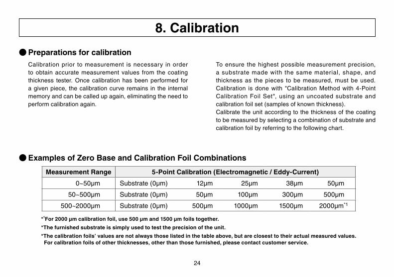
● Preparations for calibration
● Examples of Zero Base and Calibration Foil Combinations
Measurement Range 5-Point Calibration (Electromagnetic / Eddy-Current)
0~50μm Substrate (0μm) 12μm 25μm 38μm 50μm
50~500μm Substrate (0μm) 50μm 100μm 300μm 500μm
500~2000μm Substrate (0μm) 500μm 1000μm 1500μm 2000μm*1
*1For2000µmcalibrationfoil,use500µmand1500µmfoilstogether.
*The furnished substrate is simply used to test the precision of the unit.
*The calibration foils’ values are not always those listed in the table above, but are closest to their actual measured values. For calibration foils of other thicknesses, other than those furnished, please contact customer service.
Calibration prior to measurement is necessary in order to obtain accurate measurement values from the coating thickness tester. Once calibrationhasbeen performed foragivenpiece, thecalibrationcurveremains in the internalmemoryandcanbecalledupagain,eliminatingtheneedtoperform calibration again.
Toensure thehighest possiblemeasurement precision,a substratemade with the samematerial, shape, andthicknessas thepieces to bemeasured,must beused.Calibration is donewith "CalibrationMethodwith 4-PointCalibrationFoilSet", usinganuncoated substrate andcalibrationfoilset(samplesofknownthickness).Calibratetheunitaccordingtothethicknessofthecoatingto be measured by selecting a combination of substrate and calibration foil by referring to the following chart.
8. Calibration

25
● Calibration Procedure
Procedure Example : Calibration with electromagnetic measurement mode , usingasubstrateand4calibrationsfoils(100,300,500,700µm).
First,setanapplicationnumberfortheapplication(calibrationcurve),referringto1Applicationonp.14.The rest of the procedure is described below. * Once set, the application number remains in memory even after the power is switched off.
Step Operation Display Explanation
1 and First, performsubstrate calibration.Switch on thepower,
and then place the cursor over SET by pressing the →keyonthemeasurementscreen,andpresstheEnterkey.
2 or and Place the cursor on Substrate Cal. by pressing the ↑ or
↓key.ThenpresstheEnterkeytoswitchtothesubstratecalibration setting screen.
3
Midair measurement PointtheprobeintheairandpresstheEnterkey.Measurement is performed automatically 7 times.
・・・・
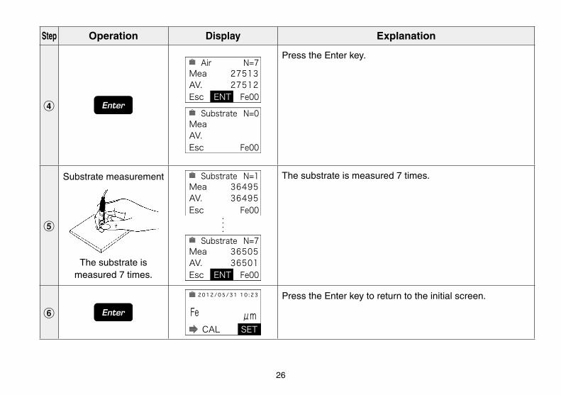
26
Step Operation Display Explanation
4
PresstheEnterkey.
5
Substrate measurement
The substrate is measured 7 times.
The substrate is measured 7 times.
6
PresstheEnterkeytoreturntotheinitialscreen.
・・・・

27
Step Operation Display Explanation
7 or
SelectCALby pressing the ← or →key.* The display shows the previous measurement mode (Fe or NFe).
8
PresstheEnterkeytoswitchtothecalibrationdisplay.
9
Substrate measurement
The substrate is measured 4 or 5 times.
Measurean uncoated substrate 4 or 5 times. Each timeameasurement is completed, a beep soundsand themeasured value is displayed.
* The electromagnetic measurement mode is used for ferrous
substrates (Fe), and the eddy-current measuring mode is used for
non-ferrous metal substrates (NFe).
*Dependingonthematerial,ameasurementvaluethatgreatly
differs from that shown on the left (a measurement value close to
0)maybedisplayed,butthisvaluewillbesettothesettingvalue
through steps 0 and !, so continue with the operation.
・・・・
1
2
5

28
Step Operation Display Explanation
0 and
numerickeypad
Press theEnter keyand check that the thickness (0.0μm) of the substrate coating is displayed. To change the thicknessofthesubstratecoating,deletethevaluewiththeDel key, andenter thedesired thicknessof the substratecoatingfromthenumerickeypad.
!
Press theEnter key to set the substrate.The displaychanges fromStandard0 toStandard1,so theoperationgoes to measurement using a calibration foil.
* If Esc is selected on the display during step 9 or ! and the Enter
key is pressed, substrate calibration is not set.
@
Measurement of 100μm calibration foil
Place the calibration foil on the substrate and perform measurement
4 or 5 times.
Place the calibration foil (the 100 μm plastic foil) on the substrate and perform measurement 4 or 5 times.*Dependingonthematerial,ameasurementvaluethatgreatly
differs from that of the calibration foil thickness may be displayed,
but this value will be set to the setting value through steps # and
$, so continue with the operation.
*Calibration using calibration foils should be done in order of
increasing thickness, starting with the thinnest calibration foil.
1
2
5
・・・・

29
* If performing calibration with 4 (substrate and 3 calibration foils) or fewer points, calibrate only the number of calibration foils required,
and then after step $, press the Enter key again.
Step Operation Display Explanation
# and
numerickeypad
Press theEnterkey.Clear thenumericvaluewith theDelkeyandenter the thickness(100μm)of thecalibration foilfromthenumerickeypad.
$
PresstheEnterkeytosetthecalibrationfoil(100μm).Thedisplays changes from Standard 1 to Standard 2.
%
Repeat steps @ # and $ to measure and set the calibration foil (300 μm)
Measure and set the calibration foil (500 μm)
Measure and set the calibration foil (700 μm)
Proceed to the calibration of the second calibration foil (300 μm).CheckthatthescreendisplaysStandard2,andrepeat steps @ # and $.
Proceed to the calibration of the third calibration foil (500 μm).CheckthatthescreendisplaysStandard3,andrepeatsteps @ # and $.
Proceed to the calibration of the fourth calibration foil (700 μm).Check that the screendisplaysStandard4, andrepeat steps @ # and $.
・・・・・
・・・・・

30
* The purpose of performing measurement 4 to 5 times for each
calibration using a substrate and calibration foils is to obtain the
average value.
*Duringcalibration in thecontinuousmeasurementmode(seep.23),
in steps 5 9 and @ place the probe tip on the measurement surface,
and once the measurement value has stabilized, press the Enter key.
The value displayed at that time is recorded as calibration data.
* If a recent measurement value is displayed on the display, it can be
clearedwiththeDelkey.
*WhenEscisdisplayedonthedisplay,youcanreturntothedisplay
in step 7. To do so, press the → key, select Esc , and then press
the Enter key. In this case, the calibration settings are canceled.
Step Operation Display Explanation
^
PresstheEnterkeytoreturntotheinitialdisplay.
* If Esc is selected on the display during step @ through ^ and the
Enter key is pressed, the calibration settings are canceled.

31
● The Battery AlarmWhen the battery alarm symbol isdisplayed,immediatereplacetonewbatteries(1.5ValkalineAAsize,4pcs.).Refer to p.10 (1) Insert the batteries.
9.BatteryReplacement
32
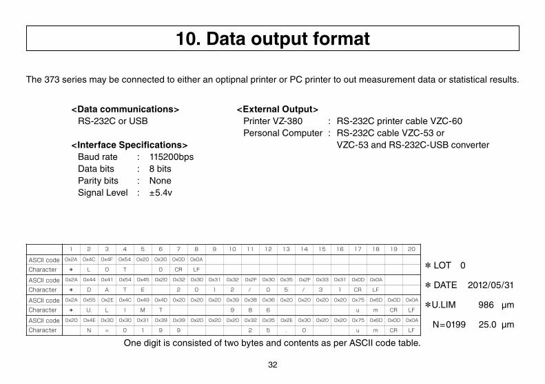
OnedigitisconsistedoftwobytesandcontentsasperASCIIcodetable.
The 373 series may be connected to either an optipnal printer or PC printer to out measurement data or statistical results.
Character
ASCII code
Character
ASCII code
Character
ASCII code
Character
*LOT 0
*DATE 2012/05/31
*U.LIM 986μm
N=0199 25.0 μm
10.Dataoutputformat
<Datacommunications> RS-232CorUSB
<Interface Specifications> Baud rate : 115200bps Data bits : 8 bits Parity bits : None SignalLevel : ±5.4v
<External Output> PrinterVZ-380 : RS-232CprintercableVZC-60 PersonalComputer : RS-232CcableVZC-53or VZC-53andRS-232C-USBconverter

33
11. Troubleshooting
Check Items Verification Action
Power supply Arethebatteriesproperlyset? ● Open the battery compartment cover at the rear of the unit and check.(See"Insertthebatteries"onp.10.)
Arethebatteriesexhausted? ● If theyare exhausted, replace themwith four newsize AAalkalinebatteries.(See "BatteryAlarm" onp.31 and "Insert thebatteries"onp.10.)
Probe selection Hasthecorrectprobebeenselected? ● Checkwhethertherightprobehasbeenselectedforthepiecetobemeasured.(See"SelectingandConnectingtheprobe"onp.10.)
Probe setting Istheconnectordeformed? ● Iftheconnectorisdeformed,replaceitwithanewone.
Istheconnectorsoiled? ● Iftheconnectorparthasforeignmatteronit,cleanitbywipingitwithasoftclothdampenedwithbenzene,alcohol,etc.
Probe usage Istheprobeusedcorrectly? ● Duringmeasurement, ensure that the tip of theprobe is incontactwith themeasurement surface. (See "Probeusagemethod"onp.11.)
Symptom State Action
The measurementvalue is not fixed.
The measurement method is set to Continues.
● See"%Hold/Continues"onp.23andsetthemethodtoHold.
E1isdisplayed. No probe is attached. ●Attachaprobe. (See"SelectingandConnectingtheprobe"onp.10.)
E2isdisplayed. Aprobenotsupportedbytheunitisattached.
● Attachthecorrectprobe. (See"SelectingandConnectingtheprobe"onp.10.)
Err-----isdisplayed. The measurement value is out of the displayable range.
●Usetheunitwithinitsmeasurementrange. (See"MeasurableRange"onp.9".)

34
(1) Confirm the type of material being measured.
Besuretocheckthetypeofmaterialandselectthecorrectprobetypebeforebeginningmeasurements.
(2)Donotdamagetheprobeorgetitdirty.
Accuratemeasurementresultscannotbeobtainedifthechiponthetipoftheprobeisdamagedordirty.Donotpound the probe against the measurement surface or move the probe laterally while it is pressed down upon thesurface.Whenfinishedmakingmeasurements,useasoftclothwetwithbenzineoralcoholtocleanthetipof the probe.
(3) Handle the calibration foils with care.
Thethicknessofthecalibrationfoilshasbeenmeasuredveryprecisely.Youwillnotbeabletoobtainaccuratemeasurementresults ifyouusecalibration foilswhichhavebeenscratched,bentorotherwisedamaged.Beparticularlycarefulnottosubjectthethinnestfoil,the10μmfoil,towear.
Ifastandardfoilbecomesdamagedwhilebeingused,pleasecontactthedealerfromwhomyoupurchasedthetesterandorderareplacementofthesamethickness.Althoughthethicknessofreplacementfoilsmayslightlydifferentthanthatoftheoriginalfoils,thisdoesnotposeaproblemforcalibrationadjustments.
(4)Adjustment&Inspection
Inordertomaintainpreciseperformancethecoatingthicknesstestersshouldbeinspectedatleastonceperyear. Please contact the dealer from whom you purchasd your unit regarding inspection.
Caution
Caution
12. Notes for Measuring and Handling


1205・MA・0301・400