355.2-01 evaluating the performance of post-installed...
TRANSCRIPT

Evaluating the Performance of Post-InstalledMechanical Anchors in Concrete
Reported by ACI Committee 355
ACI 355.2-01
William H. Alderman Richard J. Ernst Harry B. Lancelot, III Richard S. Orr
Tarek Aziz Herman L. Graves, III Alexander Makitka Andrew Rossi
Ranjit L. Bandyopadhyay Kevin D. Heinert Lee Mattis Dan R. Stoppenhagen
Peter J. Carrato Christopher Heinz Robert R. McGlohn Patrick J. E. Sullivan
Ronald A. Cook Bruce Ireland Donald F. Meinheit Harry Wiewel
Rolf Eligehausen Richard E. Klingner Francis A. Oluokun
Richard E. WollmershauserChairman
Harry ChambersSecretary
Note: Special recognition is made to Werner Fuchs for contributions to the development of this document.
ACI 355.2 prescribes testing programs and evaluation requirements forpost-installed mechanical anchors intended for use in concrete under thedesign provisions of ACI 318. Criteria are prescribed for determiningwhether anchors are acceptable for use in uncracked concrete only, or incracked as well as uncracked concrete. Performance categories for anchorsare established, as are the criteria for assigning anchors to each category.The anchor performance categories are used by ACI 318 to assign capacityreduction factors and other design parameters.
Keywords: anchors; cracked concrete; expansion anchors; fasteners;mechanical anchors; post-installed anchors; undercut anchors.
CONTENTSChapter 1—Scope, p. 355.2-2
Chapter 2—Definitions and notation, p. 355.2-22.1—Definitions2.2—Notation
Chapter 3—Significance and use, p. 355.2-5
Chapter 4—Requirements for anchor identification, p. 355.2-5
4.1—Determination of critical characteristics of anchors
Chapter 5—General requirements, p. 355.2-65.1—Testing sequence5.2—Test samples5.3—Testing by manufacturer5.4—Changes to product
Chapter 6—Requirements for test specimens, installation of anchors, and conduct of tests, p. 355.2-8
6.1—Concrete for test members6.2—Anchor installation
355.2-1
ACI 355.2-01 became effective January 12, 2002.Copyright 2002, American Concrete Institute.All rights reserved including rights of reproduction and use in any form or by any
means, including the making of copies by any photo process, or by electronic ormechanical device, printed, written, or oral, or recording for sound or visual reproduc-tion or for use in any knowledge or retrieval system or device, unless permission inwriting is obtained from the copyright proprietors.
6.3—Test methods6.4—Tests in cracked concrete6.5—General requirements for anchor behavior
Chapter 7—Reference tests, p. 355.2-117.1—Purpose7.2—Reference tension tests for single anchors withoutspacing and edge effects7.3—Required calculations using results of reference tests
Chapter 8—Reliability tests, p. 355.2-128.1—Purpose8.2—Reliability tests using reduced installation effort8.3—Reliability in low-strength concrete with large drill bit8.4—Reliability in high-strength concrete with small drill bit8.5—Reliability under repeated load8.6—Reliability in cracks where opening width is cycled
Chapter 9—Service-condition tests, p. 355.2-149.1—Purpose9.2—General test conditions9.3—Service-condition tension test with a single anchorwith two edges (corner)9.4—Service-condition test at minimum edge distance andminimum spacing9.5—Service-condition shear test for single anchors with-out spacing and edge effects9.6—Service-condition, simulated seismic tension tests9.7—Service-condition, simulated seismic shear tests

355.2-2 ACI STANDARD
Chapter 10—Establishing anchor categories, p. 355.2-16
Chapter 11—Presenting anchor data, p. 355.2-1611.1—Data analysis11.2—Format of the data sheet11.3—General requirements11.4—Contents of evaluation report
Chapter 12—Requirements for independent testing and evaluation agency, p. 355.2-16
Chapter 13—References, p. 355.2-1713.1—Referenced standards
Appendix A1—Requirements for normalization of results, p. 355.2-17
A1.1—Normalization of capacities to take account of con-crete and steel strengthsA1.2—Concrete breakout or splitting failureA1.3—Pullout and pull-through failureA1.4—Steel failure
Appendix A2—Requirements for establishing characteristic capacities, p. 355.2-17
A2.1—ScopeA2.2—Procedure
Appendix A3—Requirements for test members, p. 355.2-17
A3.1—Tests in uncracked concreteA3.2—Tests in cracked concreteA3.3—Casting and curing of test members
CHAPTER 1—SCOPE1.1 ACI 355.2 prescribes testing and evaluation require-
ments for post-installed mechanical anchors intended for usein concrete according to the design criteria of ACI 318 Build-ing Code Requirements for Structural Concrete. Criteria areprescribed for determining whether anchors are acceptable foruse in uncracked concrete only, or in cracked as well as un-cracked concrete. Criteria are prescribed for determining theperformance category into which each anchor shall be placed.The anchor performance categories are used by ACI 318 to as-sign capacity reduction factors and other design parameters.
1.2 ACI 355.2 describes the tests required to qualify apost-installed mechanical anchor or anchor system for useunder the provisions of ACI 318.
1.3 ACI 355.2 applies only to post-installed mechanicalanchors (torque-controlled expansion anchors, displace-ment-controlled expansion anchors, and undercut anchors),placed into predrilled holes and anchored within the concreteby mechanical means.
1.4 ACI 355.2 applies only to anchors with a nominal di-ameter of 1/4 in. (6 mm) or larger.
1.5 The values stated either in inch-pound units or SI unitsare to be separately regarded. Within the text, the SI units areshown in parentheses. The values in each system are not ex-act equivalents; therefore, each system shall be used inde-pendently of the other. Combining values from the twosystems shall result in nonconformance with ACI 355.2.
CHAPTER 2—DEFINITIONS AND NOTATION2.1—Definitions
2.1.1 Anchor category—The classification for an anchorthat is established on the basis of the performance of the an-chor in reliability tests (see Section 10.0).
2.1.2 Anchor group—A number of anchors of approxi-mately equal effective embedment depth with each anchorspaced at less than three times its embedment depth from oneor more adjacent anchors.
2.1.3 Anchor system—A set of similar anchors that varyonly due to diameter or embedment length; a product line ofa single manufacturer.
2.1.4 Characteristic value—The 5% fractile (value with a95% probability of being exceeded, with a confidence of90%).
2.1.5 Concrete breakout failure—A concrete cone or edgefailure of the test member due to setting of the anchor or toapplied loads, in either tension or shear.
2.1.6 Cracked concrete—A test member with a uniformcrack width over the depth of the concrete member.
2.1.7 Displacement-controlled expansion anchor—Apost-installed anchor that derives its tensile holding strengthby expansion against the side of the drilled hole throughmovement of an internal plug in the sleeve or throughmovement of the sleeve over an expansion element (plug)(see Fig. 2.1). Once set, no further expansion can occur.
2.1.8 Pullout failure—A failure mode in which the anchorpulls out of the concrete without a steel failure and without aconcrete cone failure at the installed embedment depth. Theanchor may displace toward the surface, resulting in a con-crete cone failure at a load that is not consistently repeatable.
2.1.9 Pull-through failure—A failure mode in which theanchor body pulls through the expansion mechanism withoutdevelopment of the full concrete capacity.
2.1.10 Setting of an anchor—The process of expanding ananchor in a drilled hole.
2.1.11 Splitting failure—A concrete failure mode in whichthe concrete fractures along a plane passing through the axisof the anchor or anchors.
2.1.12 Statistically equivalent—Two groups of test resultsshall be considered statistically equivalent if there are no sig-nificant differences between the means or between the stan-dard deviations of the two groups. Statistical equivalence ofthe means of two groups shall be evaluated using a one-sidedt-test at a confidence of 90%.
2.1.13 Steel failure—Failure mode characterized by frac-ture of the steel anchor parts transmitting tension loads,shear loads, or both to the point of load introduction intothe concrete.
Fig. 2.1—Examples of displacement-controlled expansion anchors.

EVALUATING THE PERFORMANCE OF POST-INSTALLED MECHANICAL ANCHORS 355.2-3
2.1.14 Test series—A group of tests having the same testparameters.
2.1.15 Torque-controlled expansion anchor—A post-in-stalled expansion anchor that derives its tensile holdingstrength from the expansion of one or more sleeves or otherelements against the sides of the drilled hole through the ap-plication of torque, which pulls the cone(s) into the expan-sion sleeve(s) (see Fig. 2.2). After setting, tensile loading cancause additional expansion (follow-up expansion).
2.1.16 Uncracked concrete—In these tests, concrete ele-ments that are expected to remain uncracked unless the crackis part of the anchor failure mode.
2.1.17 Undercut anchor—A post-installed anchor that de-rives its tensile holding strength by the mechanical interlockprovided by undercutting the concrete, achieved either by a spe-cial tool or by the anchor itself during installation (see Fig. 2.3).
Fig. 2.3(b)—Type 2 undercut anchor. Displacement-con-trolled anchor set in predrilled undercut by hammeringsleeve over cone.
Fig. 2.3(a)—Type 1 undercut anchor. Load-controlledanchor installed by tensioning anchor causing sleeve toexpand into predrilled undercut.
Fig. 2.3(c)—Type 3 undercut anchor. Displacement-con-trolled anchor set in predrilled undercut by pulling cone up,causing expansion sleeve to expand into undercut.
2.2—NotationAN = projected area of the failure surface for an an-
chor or group of anchors, approximated as thebase of the pyramid that results from projectingthe failure surface outward 1.5 hef from the cen-terline of the anchor, or in the case of a group ofanchors, from a line through the centerlines of arow of adjacent anchors (Fig. 2.4); not to be tak-en greater than nANO, in.2 (mm2)
ANO = projected area of the failure surface of a singleanchor remote from edges: 9 h2
ef, (see Fig. 2.5),in.2 (mm2)
Ase = effective tensile stress area of anchor, in.2
(mm2) cmin = minimum allowable edge distance as deter-
mined from testing and given in the manufac-turer’s data sheets, in. (mm)
dm = diameter of a carbide-tipped drill bit with a di-ameter on the low end of the carbide diametertolerance range for a new bit, representing amoderately used bit, in. (mm)
dmax = diameter of a carbide-tipped drill bit with a di-ameter on the high end of the carbide diametertolerance range for a new bit, representing a bitas large as would be expected in use, in. (mm)
dmin = diameter of a carbide-tipped drill bit with a di-ameter below the low end of the carbide diame-ter tolerance range for a new bit, representing awell-used bit, in. (mm)
do = outside diameter of post-installed anchor, in.(mm)
Fig. 2.2—Examples of torque-controlled expansion anchors.
fc,m,i = concrete compressive strength to which test re-sults for Test Series i are to be normalized usingEq. A1.1, lb/in.2 (MPa)
fc,test,i = mean concrete compressive strength measuredwith standard cylinders, for concrete of TestSeries i, lb/in.2 (MPa)
fut = specified ultimate tensile strength of anchorsteel, lb/in.2 (MPa)
f u,test = mean ultimate tensile strength of anchor steel asdetermined by test, lb/in.2 (MPa)
fy = specified yield strength of anchor steel, lb/in.2
(MPa)

355.2-4 ACI STANDARD
Fig. 2.3(f)—Type 6 undercut anchor. Torque-controlledanchor that cuts its own undercut by application of settingtorque that forces sleeve over cone.
Fig. 2.3(e)—Type 5 undercut anchor. Torque-controlledanchor set into predrilled undercut by application of torqueforcing sleeve over cone (two examples shown).
Fig. 2.3(d)(continued)—Type 4 undercut anchor. Displace-ment-controlled anchor that cuts its own undercut whilebeing set by hammering sleeve over cone.
Fig. 2.4—Projected areas AN for single anchors and groupsof anchors.
Fig. 2.5—Projected area ANo for single anchor.
Fm,i = mean normalized capacity in Test Series i, ascalculated using Eq. (A1-1), lb (N)
Fut = normalized anchor capacity, lb (N)Fu,test,i = mean anchor capacity as determined from Test
Series i, lb (N)F5% = characteristic capacity in a test series, calculated
according to Appendix A2, lb (N)
h = thickness of structural member in which an an-chor is installed, measured perpendicular to theconcrete surface at the point where the anchor isinstalled, in. (mm)
hef = effective embedment depth, measured from theconcrete surface to the deepest point at whichthe anchor tension load is transferred to the con-crete (see Fig. 2.6), in. (mm)
hmin = minimum member thickness as specified by theanchor manufacturer, in. (mm)
k = effectiveness factor, whose value depends onthe type of anchor
K = statistical constant (one-sided tolerance factor)used to establish the 5% fractile with a 90%confidence, and whose value depends on thenumber of tests (Appendix A2)
n = number of anchors in a test series; also, numberof anchors in a group
N = normal force (generally tensile), lb (N)Nb = characteristic tensile capacity of an anchor with
a concrete failure mode (5% fractile of test re-sults), lb (N)
Nb,o = characteristic capacity in reference tests, lb (N)Nb,r = characteristic capacity in reliability tests, lb (N)Neq = maximum seismic tension test load, equal to
50% of the mean tension capacity in crackedconcrete from reference tests, lb (N)

EVALUATING THE PERFORMANCE OF POST-INSTALLED MECHANICAL ANCHORS 355.2-5
Fig. 2.6—Effective embedment depth.
Nk = lowest characteristic capacity in reference testsin uncracked concrete for concrete, steel, orpullout failures for the concrete strength of thetest member, lb (N)
Np = characteristic tensile pullout or pull-through ca-pacity of an anchor (5% fractile of test results),lb (N)
Nst = characteristic tensile steel capacity of an an-chor, lb (N)
Nu = ultimate load measured in a tension test, lb (N) Nw = tensile load in tests in cracks whose opening
width is cycled, lb (N)N1 = minimum tension load above which variations
in the load-displacement curve are acceptable,as prescribed in Section 6.5.1.1, lb (N)
N10% = load at 10% of the ultimate load measured in thetension test, lb (N)
N30% = load at 30% of the ultimate load measured in thetension tests, lb (N)
smin = minimum spacing used in Table 5.1, Test 8 and
Table 5.2, Test 10, in. (mm)T = applied torque in a test, ft-lb (N·m)Tinst = specified or maximum setting torque for expan-
sion or prestressing of an anchor, ft-lb (N·m)Veq = maximum cyclic shear test load in the seismic
shear tests, determined by calculation or by test,lb (N)
Vst = characteristic shear capacity for steel failure,lb (N)
w = crack-opening width, in. (mm)∆w = change in crack-opening width, in. (mm)∆10% = displacement measured at 10% of ultimate load
in tension test, lb (N)∆30% = displacement measured at 30% of ultimate load
in tension test, lb (N)β = axial stiffness of anchor in service load range,
lb/in. (kN/mm)φIR = capacity reduction factor developed from tests
for installation reliabilityν = sample coefficient of variation (standard devia-
tion divided by the mean) expressed as decimalfraction or in percent
CHAPTER 3—SIGNIFICANCE AND USE3.1—ACI 355.2 applies to post-installed mechanical an-
chors intended for use in structural applications addressed byACI 318 and subjected to static or seismic loads in tension,shear, or combined tension and shear. Applicable anchorsare shown in Fig. 2.1, 2.2, and 2.3. It does not apply to an-chors loaded in compression if the expansion mechanism is
also loaded in compression, nor to anchors subjected to long-term fatigue loading. Anchors meeting the requirements ofACI 355.2 are expected to sustain their design loads (in ten-sion, shear, and combined tension and shear) while provid-ing adequate stiffness. The requirements of ACI 355.2related to qualification of anchors for seismic applications donot simulate the behavior of anchors in plastic hinge zones ofreinforced concrete structures.
CHAPTER 4—REQUIREMENTS FOR ANCHOR IDENTIFICATION
4.1—Determination of critical characteristics of anchors
The anchor manufacturer, in consultation with the inde-pendent testing and evaluation agency (Section 12.0), shalldetermine the characteristics affecting the identification andperformance of the anchor being evaluated. These character-istics can include (but are not limited to) dimensions, constit-uent materials, surface finishes, coatings, fabricationtechniques, and the marking of the anchors and components.
4.2—Specification of critical characteristics of anchors
The manufacturer shall include in the drawings and speci-fications for the anchor those characteristics determined tobe critical (Section 4.1).
4.3—Verification of conformance to drawings and specifications
4.3.1 Dimensions—Dimensions determined to be critical(Section 4.1) shall be checked by the independent testing andevaluation agency (Section 12.0) for conformance to thedrawings and specifications (Section 4.2).
4.3.2 Constituent materials—Constituent materials deter-mined to be critical (Section 4.1) shall be checked by the in-dependent testing and evaluation agency (Section 12.0) forconformance to mechanical and chemical specifications(Section 4.2), using certified mill test reports for steels, andusing similar certified documents for other materials.
4.3.3 Surface finishes—Surface finishes determined to becritical (Section 4.1) shall be checked by the independenttesting and evaluation agency (Section 12.0) for conform-ance to drawings and specifications (Section 4.2). This checkmay include characteristics such as surface hardness orroughness.
4.3.4 Coatings—Coatings determined to be critical (Sec-tion 4.1) shall be checked by the independent testing andevaluation agency (Section 12.0) for compliance with draw-ings and specifications (Section 4.2). This check may in-clude characteristics such as coating thickness or surfaceroughness.
4.3.5 Fabrication techniques—Fabrication techniquesdetermined to be critical (Section 4.1) shall be checked bythe independent testing and evaluation agency (Section12.0) for compliance with the drawings and specifications(Section 4.2). These fabrication techniques might includemachining techniques (for example, cold-forming versusmachining), or surface treatment (for example, heat-treat-ment or shot-peening).
4.3.6 Markings—Markings determined to be critical (Sec-tion 4.1) shall be checked by the independent testing andevaluation agency (Section 12.0) for compliance with draw-ings and specifications (Section 4.2).

355.2-6 ACI STANDARD
Table 5.1—Test program for evaluating anchor systems for use in uncracked concrete
Test number Reference Purpose Description
Concrete strength
Member thickness
Drill bit diameter
Minimum sample size,* n
Reference tests
1 7.2 Low-strength concrete
Tension—single anchor away from edges Low ≥ hmin dm 5
2 7.2 High-strength concrete
Tension—single anchor away from edges High ≥ hmin dm 5
Reliability tests
3 8.2 Sensitivity to reduced installation effort
Tension—single anchor away from edges
Varies with
anchor type
≥ hmin dm† 5
4 8.3 Sensitivity to large hole diameter
Tension—single anchor away from edges Low ≥ hmin dmax 5
5 8.4 Sensitivity to small hole diameter
Tension—single anchor away from edges High ≥ hmin dmin 5
6 8.5 Reliability under repeated load
Repeated tension—single anchor away from edges, residual capacity
Low ≥ hmin dm 5‡
Service-condition tests
7 9.3
Verification of full concrete capacity in corner with edges located at 1.5 hef
Tension—single anchor in corner with edges
located at 1.5 hef
Low hmin dm 4
8 9.4
Minimum spacing and edge distance to preclude splitting on
installation
High installation tension (torque or direct)—two
anchors near edgeLow hmin dm 5
9 9.5Shear capacity of
steel§|Shear—single anchor
away from edges Low ≥ hmin dm 5
*All diameters unless noted otherwise.†Drilling diameters for undercuts are different and are given in Table 6.6.‡Test smallest, middle, and largest anchor diameter.§Required only for anchors whose cross-sectional area, within five anchor diameters of the shear failure plane, is less than that of a threaded bolt of the same nominal diameter as the anchor; or for sleeved anchors when shear capacity of the sleeve will be considered.
4.3.7 Quality control—Anchors shall be manufacturedunder a certified quality system meeting the requirementsof the ISO 9000 quality management system of equivalentnational standard. Manufacturers shall undergo a conformityassessment by an accredited quality-system registrar, andshall maintain a certification or registration in conformanceto that standard.
CHAPTER 5—GENERAL REQUIREMENTS5.1—Testing sequence
Perform four types of tests in the following sequence: 1. Identification tests to evaluate the anchor’s compliance
with the critical characteristics determined in Section 4.1; 2. Reference tests to establish baseline performance against
which subsequent tests are to be compared (Section 7.0); 3. Reliability tests to confirm the reliability of the anchor
under adverse installation procedures and long-term use(Section 8.0); and
4. Service-condition tests to evaluate the performance ofthe anchor under expected service conditions (Section 9.0).
Test requirements are summarized in Tables 5.1 and 5.2.Determine the acceptability or unacceptability of the anchorusing the criteria prescribed in Sections 4.0, 7.0, 8.0, and 9.0.Determine the anchor category (an index of the anchor’s sen-sitivity to conditions of installation and use) using the crite-ria prescribed in Section 10.0. Report the lowest category by
diameter as prescribed in Section 11.0. For anchors withmultiple embedments, refer to Table 6.7.
5.2—Test samplesThe independent testing and evaluation agency (Section
12.0) shall visit the manufacturing or distribution facility,shall randomly select anchors for testing, and shall verifythat the samples are representative of the production of themanufacturer as supplied to the marketplace. To test newlydeveloped anchors that are not in production, use samplesproduced by the expected production methods. After produc-tion has begun, perform identification and reference tests toverify that the constituent materials have not changed, andthat the performance of the production anchors is statisticallyequivalent to that of the anchors originally evaluated. SeeSection 2.1.12.
5.2.1 When internally threaded anchors are supplied with-out fastening items, such as bolts, the manufacturer shallspecify the bolts to be used. To achieve concrete breakoutfailure for comparison with Eq. (7-1), it shall be permitted to
use bolts of higher strength than those specified, providedthat those bolts do not change the functioning, setting, or fol-low-up expansion of the anchors.5.2.2 Perform separate reference and reliability tests in ac-cordance with Table 5.1 or Table 5.2 for each anchor materialand production method. If the results of the reference and re-liability tests for the anchors of each material and production

EVALUATING THE PERFORMANCE OF POST-INSTALLED MECHANICAL ANCHORS 355.2-7
Table 5.2—Test program for evaluating anchor systems for use in crackedand uncracked concrete
Test number Reference Purpose Description
Crack opening width w, in.
Concrete strength
Member thickness
Drill bit diameter
Minimum sample size,* n
Reference tests
1 7.2Reference test in uncracked low-
strength concrete
Tension—single anchor away from
edges— Low ≥ hmin dm 5
2 7.2Reference test in uncracked high-strength concrete
Tension—single anchor away from
edges— High ≥ hmin dm 5
3 7.2Reference test in
low-strength, cracked concrete
Tension—single anchor away from
edges0.012 Low ≥ hmin dm 5
4 7.2Reference test in
high-strength, cracked concrete
Tension—single anchor away from
edges0.012 High ≥ hmin dm 5
Reliability tests
5 8.2Sensitivity to
reduced installation effort
Tension—single anchor away from
edges0.012 Varies with
anchor type≥ hmin dm
† 5
6 8.3Sensitivity to crack width and large hole
diameter
Tension—single anchor away from
edges0.020 Low ≥ hmin dmax 5
7 8.4Sensitivity to crack
width and small hole diameter
Tension—single anchor away from
edges0.020 High ≥ hmin dmin 5
8 8.6Test in cracks whose
opening width is cycled
Sustained tension—single anchor away from edges, residual
capacity
0.004 to 0.012 Low ≥ hmin dmax§ 5
Service-condition tests
9 9.3
Verification of full concrete capacity in corner with edges located at 1.5 hef
Tension—single anchor in corner with
edges located at 1.5 hef
— Low hmin dm 4
10 9.4
Minimum spacing and edge distance to preclude splitting on
installation in uncracked concrete
High installation tension (torque or
direct)—two anchors near edge
— Low hmin dm 5
11 9.5Shear capacity in
uncracked concrete steel‡
Shear—single anchor away from edges — Low ≥ hmin dm 5
12 9.6 Seismic tensionPulsating tension,
single anchor, away from free edge
0.020 Low ≥ hmin dm 5
13 9.7 Seismic shearAlternating shear,
single anchor, away from free edge
0.020 Low ≥ hmin dm 5
*All diameters unless noted otherwise.†Drilling diameters for undercuts are different and are given in Table 6.6.‡Required only for anchors whose cross-sectional area, within five anchor diameters of the shear failure plane, is less than that of a threaded bolt of the same nominal diameter as the anchor; or for sleeved anchors when shear capacity of the sleeve will be considered.§Test for undercut anchors use dm.
method are statistically equivalent (Section 2.1.12), the ser-vice-condition tests of Table 5.1 (Tests 7, 8, and 9), and ofTable 5.2 (Tests 9, 10, and 11) shall be permitted to be per-formed for one anchor material and production method only.Otherwise, perform the complete test program for each an-chor material and production method.
5.2.3 The sample sizes given in Table 5.1 and 5.2 are theminimum. At the discretion of the independent testing andevaluation agency or manufacturer, the sample size shall bepermitted to be increased.
5.3—Testing by manufacturerAll reference and reliability tests shall be performed by the
independent testing and evaluation agency (Section 12.0).
Not more than 50% of the service-condition tests required byACI 355.2 shall be permitted to be performed by the manu-facturer. All such tests shall be witnessed by an independenttesting laboratory or engineer meeting the requirements ofSection 12.0. The manufacturer’s tests shall be considered inthe evaluation only if the results are statistically equivalentto those of the independent testing and evaluation agency.
5.4—Changes to productBefore an anchor is changed, the manufacturer shall report
the nature and significance of the change to the independenttesting and evaluation agency (Section 12.0), which shall de-termine which tests (if any) shall be performed. For allchanges that might affect the anchor performance, perform

355.2-8 ACI STANDARD
the reference tests and the reliability tests. If test results ofthe modified product are statistically equivalent to those ofthe originally tested product, then no additional testing is re-quired. Otherwise, test the changed products in accordancewith Table 5.1 or Table 5.2.
CHAPTER 6—REQUIREMENTS FOR TEST SPECIMENS, INSTALLATION OF ANCHORS, AND
CONDUCT OF TESTS6.1—Concrete for test members
Concrete used in testing shall meet the requirements ofSections 6.1 through 6.1.4. To verify the performance of ananchor in a particular type of concrete (for example, con-crete with higher strength and lower strength than given inACI 355.2), specify that same type of concrete for the testsof ACI 355.2.
6.1.1 Aggregates—For normalweight concrete, aggregatesshall conform to ASTM C 33 and the maximum aggregatesize shall be 3/4 or 1 in. (19 or 25 mm). For lightweight con-crete, aggregates shall conform to ASTM C 330.
6.1.2 Cement—Use portland cement conforming to ASTMC 150. The concrete mixture shall not include any other ce-mentitious materials (for example, slag, fly ash, silica fume,or limestone powder), unless otherwise specified by themanufacturer. Report if such cementitious materials or ad-mixtures are used in the concrete.
6.1.3 Concrete strength—Test anchors in test memberscast of concrete within two nominal compressive strengthranges, based on compressive strength specimens prepared
Table 6.1—Required diameters of carbide hammer-drill bits, in.
Nominal diameter, in.
Tolerance ranges
dmin, in. dm, in. dmax, in.
3/16 0.190 - 0.194 0.198 - 0.201 0.204 - 0.206
1/4 0.252 - 0.256 0.260 - 0.263 0.266 - 0.268
5/16 0.319 - 0.323 0.327 - 0.331 0.333 - 0.335
3/8 0.381 - 0.385 0.390 - 0.393 0.396 - 0.398
7/16 0.448 - 0.452 0.458 - 0.462 0.465 - 0.468
1/2 0.510 - 0.514 0.520 - 0.524 0.527 - 0.530
9/16 0.573 - 0.577 0.582 - 0.586 0.589 - 0.592
5/8 0.639 - 0.643 0.650 - 0.654 0.657 - 0.660
11/16 0.702 - 0.706 0.713 - 0.717 0.720 - 0.723
3/4 0.764 - 0.768 0.775 - 0.779 0.784 - 0.787
13/16 0.827 - 0.831 0.837 - 0.841 0.846 - 0.849
27/32 0.858 - 0.862 0.869 - 0.873 0.878 - 0.881
7/8 0.892 - 0.896 0.905 - 0.909 0.914 - 0.917
15/16 0.955 - 0.959 0.968 - 0.972 0.977 - 0.980
1 1.017 - 1.021 1.030 - 1.034 1.039 - 1.042
1-1/8 1.145 - 1.149 1.160 - 1.164 1.172 - 1.175
1-3/16 1.208 - 1.212 1.223 - 1.227 1.235 - 1.238
1-1/4 1.270 - 1.274 1.285 - 1.289 1.297 - 1.300
1-5/16 1.333 - 1.337 1.352 - 1.356 1.364 - 1.367
1-3/8 1.395 - 1.399 1.410 - 1.414 1.422 - 1.425
1-7/16 1.458 - 1.462 1.472 - 1.476 1.484 - 1.487
1-1/2 1.520 - 1.524 1.535 - 1.539 1.547 - 1.550
1-9/16 1.570 - 1.574 1.588 - 1.592 1.605 - 1.608
1-5/8 1.637 - 1.641 1.655 - 1.659 1.673 - 1.675
1-3/4 1.754 - 1.758 1.772 - 1.776 1.789 - 1.792
2 1.990 - 1.994 2.008 - 2.012 2.025 - 2.028
and tested in accordance with ASTM C 31 and ASTM C 39(see Appendix A3.3.1). These strength ranges are:
• Low-strength concrete: 2500 to 3500 lb/in.2 (17 to24 MPa); and• High-strength concrete: 6500 to 8000 lb/in.2 (46 to
57 MPa).6.1.4 Test members—Test members shall conform to the
requirements of Appendix A3.
6.2—Anchor installation6.2.1—General requirements
6.2.1.1 Install anchors according to the manufacturer’sinstructions, except as otherwise prescribed in ACI 355.2,and report any deviations.
6.2.1.2 Install anchors in a formed face of the concrete,or in concrete with a steel-troweled finish.
6.2.1.3 The components of the anchor, on which the per-formance will depend, shall not be exchanged. Bolts, nuts,and washers not supplied with the anchors shall conform tothe specifications given by the manufacturer, and these spec-ifications shall be included in the evaluation report.
6.2.2 Drill bit requirements—Drill bit requirements aregiven in Tables 5.1 and 5.2. Drill holes for anchors shall beperpendicular (within a tolerance of ±6 degrees) to the sur-face of the concrete member. Except for self-drilling anchorsand except as specified in Section 6.2.2.3 and 6.2.2.5, holesshall be made using carbide-tipped, hammer-drill bits meet-ing the requirements of ANSI B212.15.
6.2.2.1 The cutting diameter of drill bits shall conform tothe tolerances given in Table 6.1 or 6.2, and shall be checked
every 10 drilling operations to ensure continued compliance.6.2.2.2 When performing tests with bits of diameterdmax, use special test bits. Special test bits ground to the de-sired diameter shall be permitted to be used.
6.2.2.3 Drill bits with diameter dmin correspond to well-worn bits. These diameters are below the minimum diame-ters specified for new bits in ANSI B212.15.
6.2.2.4 All service-condition tests (Tables 5.1 and 5.2)use a bit of diameter dm.
6.2.2.5 For drill bits not included in the range of diametersgiven in Table 6.1 or Table 6.2, and for drill bits not coveredby ANSI B212.15, the independent testing and evaluationagency shall develop diameters for the bits that conform to theconcept of dmax, dm, and dmin as represented in those tables.
6.2.3—Torque requirements6.2.3.1 General torque requirements—When the appli-
cation of torque for any type of anchor is required by themanufacturer, torque each anchor specified in Sections6.2.3.1.1 and 6.2.3.2, except as specified in Section 8.2. If no
torque for the anchor is specified by the manufacturer, theanchor shall be finger-tight before testing.6.2.3.1.1 Apply the specified torque Tinst using a cali-brated torque wrench having a measuring error within ±5%of the specified torque. After waiting 10 min, remove thetorque on the anchor and apply a torque of 0.5 Tinst.
6.2.3.2 Setting of torque-controlled expansion anchors—Install torque-controlled expansion anchors in accordancewith Table 6.3 and the general torque requirements.
6.2.3.2.1 For tests performed with partial setting torque(Table 5.1, Test 3 and Table 5.2, Test 5; see also Table 6.3,Test 3), install and set the anchor with a setting torque of 0.5Tinst. Do not reduce the torque from this amount.

EVALUATING THE PERFORMANCE OF POST-INSTALLED MECHANICAL ANCHORS 355.2-9
Table 6.2—Required diameters of carbide hammer-drill bits, SI.
Nominal diameter, mm
Tolerance ranges
dmin, mm dm, mm dmax, mm
5 5.05 - 5.15 5.20 - 5.30 5.35 - 5.40
6 6.05 - 6.15 6.20 - 6.30 6.35 - 6.40
7 7.05 - 7.20 7.25 - 7.35 7.40 - 7.45
8 8.05 - 8.20 8.25 - 8.35 8.40 - 8.45
10 10.10 - 10.20 10.25 - 10.35 10.40 - 10.45
11 11.10 - 11.20 11.25 - 11.35 11.45 - 11.50
12 12.10 - 12.20 12.25 - 12.35 12.45 - 12.50
13 13.10 - 13.20 13.25 - 13.35 13.45 - 13.50
14 14.10 - 14.20 14.25 - 14.35 14.45 - 14.50
15 15.10 - 15.20 15.25 - 15.35 15.45 - 15.50
16 16.10 - 16.20 16.25 - 16.35 16.45 - 16.50
18 18.10 - 18.20 18.25 - 18.35 18.45 - 18.50
19 19.10 - 19.20 19.30 - 19.40 19.50 - 19.55
20 20.10 - 20.20 20.30 - 20.40 20.50 - 20.55
22 22.10 - 22.20 22.30 - 22.40 22.50 - 22.55
24 24.10 - 24.20 24.30 - 24.40 24.50 - 24.55
25 25.10 - 25.20 25.30 - 25.40 25.50 - 25.55
28 28.10 - 28.20 28.30 - 28.40 28.50 - 28.55
30 30.10 - 30.20 30.30 - 30.40 30.50 - 30.55
32 32.15 - 32.25 32.35 - 32.50 32.60 - 32.70
34 34.15 - 34.25 34.35 - 34.50 34.60 - 34.70
35 35.15 - 35.25 35.35 - 35.50 35.60 - 35.70
37 37.15 - 37.25 37.35 - 37.50 37.60 - 37.70
40 40.15 - 40.25 40.40 - 40.60 40.70 - 40.80
44 44.15 - 44.25 44.40 - 44.60 44.70 - 44.80
48 48.15 - 48.25 48.40 - 48.60 48.70 - 48.80
52 52.15 - 52.25 52.40 - 52.60 52.80 - 52.95
Table 6.3—Required degree of setting torque for torque-controlled expansion anchors
Table 5.1, test number
Table 5.2, test number
Required degree of setting torque
3 5 Partial
1, 2, 4, 5, 6, 7, 8, 9, 10 1, 2, 3, 4, 6, 7, 8, 9, 10, 11, 12, 13, 14 Full*
*According to manufacturer’s installation instructions, then reduced to 50% perSection 6.2.3.1.1.
6.2.3.2.2 For the seismic tests (Table 5.2, Tests 12 and13), apply Tinst and then reduce to 0.5 Tinst before the crackis widened.
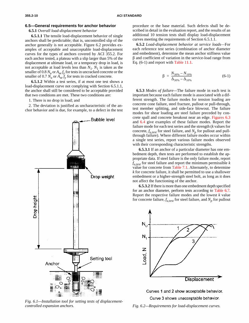
6.2.3.3 Setting of displacement-controlled expansion an-chors—Install displacement-controlled expansion anchorswith the degree of expansion specified in Table 6.4. Thespecified degrees of expansion are obtained using settingtools based on the number of drops specified in Table 6.5 forpartial and reference expansion, developed in Sections6.2.3.3.1 and 6.2.3.3.2. See Fig. 6.1 for the test fixture used
to establish the partial and reference setting expansions.6.2.3.3.1 Partial expansion—Set a minimum of five an-chors using the weight and number of drops from Table 6.5 forpartial expansion. For each anchor, measure the depth of theplug from the upper end of the anchor. Calculate the averagedepth of the plug for the set anchors and shorten the settingtool to give this setting depth. Install anchors using the short-ened setting tool for partial expansion.
6.2.3.3.2 Reference expansion—Prepare a setting tool forreference expansion using the same method as in Section6.2.3.3.1, using the weight and number of drops from Table 6.5.
Table 6.5—Parameters for establishing partial and reference expansion of displacement-controlled anchors
Anchor size1/4 in.
M65/16 in.
M83/8 in.M10
1/2 in.M12
5/8 in.M16
3/4 in.M20
Weight, lb (kg) 10 (4.5)
10 (4.5)
10 (4.5)
10 (4.5)
33 (15)
33 (15)
Height of fall, in. (mm) 18 (450)
18 (450)
18 (450)
18 (450)
24 (600)
24 (600)
Number of drops for evaluation of partial
expansion2 3 4 5 3 4
Number of drops for evaluation of reference
expansion3 5 6 7 4 5
6.2.3.4 Setting of undercut anchors—Install undercut an-chors as specified in Table 6.6. In tests of Table 5.1, Test 3and Table 5.2, Test 5, set undercut anchors using a combina-tion of the specified setting tolerances that produces the min-imum bearing surface in the concrete. Table 6.6 provides forsuch combinations for various undercut anchor types. In other
tests prescribed in Tables 5.1 and 5.2, drill a cylindrical holewith a diameter as given in Tables 5.1 or 5.2 and produce theundercut as per manufacturer’s instructions.
6.3—Test methodsTest anchors in conformance with ASTM E 488 and to the
appropriate sections (Section 7.0, 8.0 or 9.0) of ACI 355.2.
6.4—Tests in cracked concreteUse the procedure specified in Sections 6.4.1 through
6.4.3 for testing anchors in cracked concrete.6.4.1 Perform tests in concrete specimens meeting the re-
quirements of Appendix A3. Use the crack-opening width was specified for the given test. Initiate the crack and install theanchor according to Section 6.2, so that the axis of the anchorlies approximately in the plane of the crack. Install the instru-mentation for measuring crack-opening widths, and widen thecrack to the specified crack-opening width while the anchor isnot loaded. Measure the crack opening using two dial gages orelectronic transducers, one on either side of the anchor, orient-ed perpendicular to the crack.
6.4.2 Subject the anchor to the specified loading sequencewhile monitoring the crack opening width at the surface. SeeAppendix A3.
6.4.3 During the test, maintain a continuous record of theload and displacement of the anchor and of the crack width.
Table 6.4—Required degree of expansion of displacement-controlled expansion anchors
Table 5.1, test number
Table 5.2, test number
Required degree of expansion
3 5 Partial
4, 5, 6 6, 7, 8 Reference
1, 2, 7, 8, 9, 10 1, 2, 3, 4, 9, 10, 11, 12, 13, 14 Full*
*According to manufacturer’s installation instructions.
355.2-10 ACI STANDARD
6.5.1.1 The tensile load-displacement behavior of singleanchors shall be predictable; that is, uncontrolled slip of theanchor generally is not acceptable. Figure 6.2 provides ex-amples of acceptable and unacceptable load-displacementcurves for the types of anchors covered by ACI 355.2. Foreach anchor tested, a plateau with a slip larger than 5% of thedisplacement at ultimate load, or a temporary drop in load, isnot acceptable at load levels less than N1. N1 is taken as thesmaller of 0.8 Nu or Ase fy for tests in uncracked concrete or thesmaller of 0.7 Nu or Ase fy for tests in cracked concrete.
Fig. 6.1—Installation tool for setting tests of displacement-controlled expansion anchors.
6.5—General requirements for anchor behavior6.5.1 Overall load-displacement behavior
6.5.1.2 Within a test series, if at most one test shows aload-displacement curve not complying with Section 6.5.1.1,the anchor shall still be considered to be acceptable providedthat two conditions are met. These two conditions are:
1. There is no drop in load; and2. The deviation is justified as uncharacteristic of the an-
chor behavior and is due, for example, to a defect in the test
procedure or the base material. Such defects shall be de-scribed in detail in the evaluation report, and the results of anadditional 10 tension tests shall display load-displacementcurves meeting the requirements of Section 6.5.1.1.
6.5.2 Load-displacement behavior at service loads—Foreach reference test series (combination of anchor diameterand embedment), determine the mean anchor stiffness valueβ and coefficient of variation in the service-load range fromEq. (6-1) and report with Table 11.1.
(6-1)
6.5.3 Modes of failure—The failure mode in each test isimportant because each failure mode is associated with a dif-ferent strength. The failure modes for tension loading areconcrete cone failure, steel fracture, pullout or pull-through,test member splitting, and side-face blowout. The failuremodes for shear loading are steel failure preceded by con-crete spall and concrete breakout near an edge. Figures 6.3and 6.4 give examples of these failure modes. Report the
βN30% N10%–
∆30% ∆10%–------------------------------=
failure mode for each test series and the strength (k values forconcrete, fu,test for steel failure, and Np for pullout and pull-through failure). Where different failure modes occur withina single test series, report various failure modes observedwith their corresponding characteristic strengths.
6.5.3.1 If an anchor of a particular diameter has one em-bedment depth, then tests are performed to establish the ap-propriate data. If steel failure is the only failure mode, reportfu,test for steel failure and report the minimum permissible kvalue for concrete from Table 7.1. Alternately, to determine
k for concrete failure, it shall be permitted to use a shallowerembedment or a higher-strength steel bolt, as long as it doesnot affect the functioning of the anchor.6.5.3.2 If there is more than one embedment depth specifiedfor an anchor diameter, perform tests according to Table 6.7.Report the respective failure modes and the lowest k valuefor concrete failure, fu,test for steel failure, and Np for pullout
Fig. 6.2—Requirements for load-displacement curves.

EVALUATING THE PERFORMANCE OF POST-INSTALLED MECHANICAL ANCHORS 355.2-11
Table 6.6—Installation requirements for undercut anchors
Installation requirements
Type of undercut anchor (See Fig. 2.3)
Load-controlled Displacement-controlled Torque-controlled
Type 1 undercut, predrilled
Type 2 and 3 undercut, predrilled
Type 4 undercut, self-drilled
Type 5 undercut, predrilled
Type 6 undercut, self-drilled
Bit diameter for cutting
cylindrical holeMaximum Maximum Maximum Maximum Maximum
Undercutting tool diameter
Minimum specification
Minimum specification — Minimum
specification —
Tolerances on length of
undercutting tool (where applicable)
Maximum tolerance length
Maximum tolerance length Maximum Maximum
tolerance lengthMaximum
tolerance length
Length of sleeve — Minimum tolerance length — — —
Length of cylindrical hole — Maximum
tolerance lengthMaximum
tolerance length — —
Setting of anchor 75% of specified load
Sleeve flush with concrete surface
Sleeve flush with concrete surface
50% of specified value
50% of specified torque or flush to
surface
Fig. 6.3—Failure modes for anchors under tensile loading.
Fig. 6.4—Failure modes for anchors under shear loading.and pull-through failure for each diameter. Where differentfailure modes occur in a test series involving a single diam-eter and different embedment depths, report each observedfailure mode and its corresponding characteristic strength.
6.5.3.3 For pullout or pull-through failure, calculate Np(5% fractile) based on the test sample size. Report k as theminimum permissible value from Table 7.1.
CHAPTER 7—REFERENCE TESTS7.1—Purpose
Perform reference tests to obtain baseline values for the re-liability and service-condition tests. The reference test re-quirements are given in Sections 7.2 through 7.3.3, and in
7.2—Reference tension tests for single anchors without spacing and edge effects (Table 5.1, Tests 1 and 2, or Table 5.2, Tests 1, 2, 3, and 4)
Table 5.1 for uncracked concrete and in Table 5.2 forcracked concrete.
7.2.1 Requirements for reference tests—Perform tensiontests in accordance with Table 5.1, Test 1 and 2, or Table 5.2,Tests 1, 2, 3, and 4. Perform the tests according to ASTM E 488on anchors installed in low-strength and high-strength con-crete. The coefficient of variation ν of the ultimate tension

355.2-12 ACI STANDARD
Table 6.7—Required embedments for test programEmbedment depth to be tested for given
diameter
Test number for embedment depths
Shallow Deep All
Table 5.1 3, 4, 5, 6, 7, 8, 9, 10 3, 4, 5, 6, 7 1, 2
Table 5.2 5, 6, 7, 8, 9, 10, 11, 12, 13, 14 5, 6, 7, 8, 9, 12, 13 1, 2, 3, 4
(7-1)kNb
fc test i,, hef1.5
--------------------------------=
8.2—Reliability tests using reduced installation effort (Table 5.1, Test 3, and Table 5.2, Test 5)
Table 7.1—Minimum and maximum values of effectiveness factor, k
Type of test
Minimum permissible value of k
Maximum reportable value of k
Inch-pound SI Inch-pound SI
Cracked concrete 17 7 21 9
Uncracked concrete 24 10 30 13
7.3.3 For pullout failure in tension, cracked and uncrackedconcrete—For pullout or pull-through failures, calculate thecharacteristic tensile capacity Np using the test data in accor-dance with the procedure in Appendix A2, and report Np.
load in any test series shall not exceed 15%. The sample sizeshall be permitted to be increased if the coefficient of varia-tion obtained from the original sample size does not meetthis requirement. If this requirement is not met, the anchorshall be considered unqualified.
7.3—Required calculations using results of reference tests
7.3.1 For concrete failure—Calculate the value of the ef-fectiveness factor k from test results, using Eq. (7-1) andconsidering the test conditions and sample size in evaluatingNb.
If the calculated k values do not meet the minimum per-missible values of Table 7.1, determine the characteristictension resistance in accordance with Section 7.3.3. The kvalues reported in Table 11.1 shall not exceed the maximumreportable k values of Table 7.1.
7.3.2 For steel failure in tension, cracked and uncrackedconcrete—When steel failure occurs for the embedment andsteel strength reported in Table 11.1, report k as theminimum permissible value prescribed by Table 7.1.Alternatively, k shall be permitted to be determined by Eq.(7-1), using tests on the same anchor with a reducedembedment, a higher-strength steel, or both, to producefailure by concrete breakout.
CHAPTER 8—RELIABILITY TESTS8.1—Purpose
The purpose of the reliability tests is to establish that theanchor is capable of safe, effective behavior under normaland adverse conditions, both during installation and in ser-vice. The reliability test requirements are given here and inTable 5.1 for uncracked concrete and in Table 5.2 forcracked concrete.
8.2.1 Purpose—These reliability tests are intended to de-termine the sensitivity of the anchor to adverse installationconditions. Perform these tests under tension loading.
8.2.2 General test conditions—In cracked concrete, use aminimum crack-opening width of 0.012 in. (0.3 mm), exceptas noted.
8.2.2.1 Torque-controlled expansion anchors—Performtests on anchors installed in high-strength concrete with settingtorque T = 0.5Tinst and drill bit of diameter dm. See Fig. 2.2 foranchor types.
8.2.2.2 Displacement-controlled expansion anchors—Per-form tests on anchors installed in low-strength concrete, usingdrill bit of diameter dm. See Fig. 2.1 for anchor types. Installa-tion requirements for displacement-controlled expansion an-chors are prescribed in Tables 6.4 and 6.5 for partial expansion.
8.2.2.3 Torque, load, and displacement-controlled un-dercut anchors—For torque-controlled and load-controlledundercut anchors, perform tension tests using low- and high-strength concrete. For displacement-controlled undercut an-chors, perform tension tests using low-strength concrete. SeeFig. 2.3 for anchor types. Installation requirements for un-dercut anchors are prescribed in Table 6.6.
8.2.3 Requirements—The coefficient of variation ν of theultimate tension load in any test series shall not exceed 20%.The sample size shall be permitted to be increased if the co-efficient of variation of the original sample size does notmeet this requirement. If this requirement is not met, the an-chor shall be considered unqualified.
8.3—Reliability in low-strength concrete with large drill bit (Table 5.1, Test 4, and Table 5.2, Test 6)
8.3.1 Purpose—These reliability tests are performed in un-cracked concrete to evaluate the sensitivity of the anchor tolow-strength concrete and oversized holes. They are performedin cracked concrete to evaluate the sensitivity of the anchor tolow-strength concrete, oversized holes, and opened cracks.
8.3.2 General test conditions—Perform tests under ten-sion loading in low-strength concrete for all anchor types.Use a drill bit of diameter dmax. For tests of anchors incracked concrete, use a minimum crack-opening width of0.020 in. (0.5 mm).
8.3.3 Requirements—The coefficient of variation ν of theultimate tension load in any test series shall not exceed 20%.The sample size shall be permitted to be increased if the co-efficient of variation of the original sample size does notmeet this requirement. If this requirement is not met, the an-chor shall be considered unqualified.
8.4—Reliability in high-strength concrete with small drill bit (Table 5.1, Test 5, and Table 5.2, Test 7)
8.4.1 Purpose—These reliability tests are performed in un-cracked concrete to evaluate the sensitivity of the anchor tohigh-strength concrete in undersized holes. They are per-formed in cracked concrete to evaluate the sensitivity of theanchor to high-strength concrete in undersized holes andopened cracks.
8.4.2 General test conditions—Perform these tests undertension in high-strength concrete for all anchor types. Use adrill bit of diameter dmin. In cracked concrete tests, use aminimum crack-opening width of 0.020 in. (0.5 mm).

EVALUATING THE PERFORMANCE OF POST-INSTALLED MECHANICAL ANCHORS 355.2-13
8.4.3 Requirements—The coefficient of variation ν of theultimate tension load in any test series shall not exceed 20%.The sample size shall be permitted to be increased if the co-efficient of variation of the original sample size does notmeet this requirement. If this requirement is not met, the an-chor shall be considered unqualified.
8.5—Reliability under repeated load (Table 5.1, Test 6)
8.5.1 Purpose—These reliability tests are performed toevaluate the performance of the anchor under repeated loadin uncracked concrete subjected to normal building move-ments.
8.5.2 General test conditions—Subject the anchor to a pulsat-ing tensile load that varies sinusoidally between a minimumload of 0.25 Nk or [0.6 (Ase ⋅⋅ 17,400 lb/in.2 (120 MPa))], which-ever is larger; and a maximum load of 0.6 Nk or 0.8 Ase fy,whichever is smaller. The loading frequency shall be 6 Hz orless. Measure displacements continuously, or, up to the max-imum load during the first loading, and then after 10, 102,103, 104, and 105 load cycles. At the end of the cyclic load-ing, test the anchor in tension to failure.
8.5.3 Requirement—Anchor displacements shall show astabilization of movement, and the average residual capacityof the anchor shall be not less than 80% of the mean capacityin the corresponding reference test. The coefficient of varia-tion ν of the ultimate tension load in any test series shall notexceed 20%. The sample size shall be permitted to be in-creased if the coefficient of variation of the original samplesize does not meet this requirement. If this requirement is notmet, the anchor shall be considered unqualified.
8.6—Reliability in cracks where opening width is cycled (Table 5.2, Test 8)
8.6.1 Purpose—These reliability tests are performed toevaluate the performance of anchors located in cracks whoseopening width is cycled.
8.6.2 General test conditions—Before installing the an-chor, 10 opening and closing cycles shall be permitted to beapplied to stabilize crack formation. Install the anchor ac-cording to Section 6.2, so that the axis of the anchor lies ap-proximately in the plane of the crack. Open the crack to acrack-opening width w1 = 0.012 in. (0.3 mm). Apply a ten-sile load of Nw from Eq. (8-1). Cycle the crack-openingwidth between the maximum crack opening width of w1 =0.012 in. (0.3 mm) and the initial minimum crack openingwidth of w2 = 0.004 in. (0.1 mm).
(8-1)
where:Nb = characteristic tensile resistance in low-strength
cracked concrete as determined from referencetests;
φIR = capacity reduction factor based on category devel-oped from reliability tests;
= 1.0 for a Category 1 anchor= 0.85 for a Category 2 anchor= 0.7 for a Category 3 anchor
As the crack-opening width is varied cyclically, keep Nwconstant within a tolerance of ±5%. Open and close the crack1000 times at a maximum frequency of 0.2 Hz. During cy-
Nw 0.9Nb 0.7φIR( )=
cling of the crack, keep the crack opening width w1 constant.The crack opening width w2 will increase during the test (seeFig. 8.1). The difference between the maximum and mini-
Fig. 8.1—Crack-width requirements for cyclic tests incracked concrete.
mum crack-opening widths during the 1000 cycles shall beat least 0.004 in. (0.1 mm). If at any time during the conductof the test, the value of w1 – w2 falls below 0.004 in. (0.1 mm),then either the lower-bound load shall be reduced, the upper-bound load shall be increased, or both shall be implemented,until the minimum value of w1 – w2 = 0.004 in. (0.1 mm) isrestored. Note that an increase in the upper-bound load cor-responds to an increase in the maximum crack width w1 be-yond 0.012 in. (0.3 mm).
8.6.3 Measure the load-displacement behavior up to loadNw. Afterward, under Nw, measure the displacements of theanchor and the crack-opening widths w1 and w2, either con-tinuously or at least after 1, 2, 5, 10, 20, 50, 100, 200, 500,and 1000 cycles of crack opening and closing.
8.6.4 After completing the cycles of crack opening andclosing, unload the anchor, measure the displacement, andperform a tension test to failure with an initial crack openingwidth w = 0.012 in. (0.3 mm). During the test, monitor butdo not control the crack width.
8.6.5 Requirement—In each test in cracks whose openingwidth is cycled, the anchor displacement shall be less than0.080 in. (2.0 mm) after the initial 20 cycles of crack openingand closing, and less than 0.120 in. (3.0 mm) after 1000 cy-cles. This maximum allowable displacement shall not be ex-ceeded in more than 5% of the tests. If this requirement is notmet, increase the number of replicates, or repeat the testswith a reduced sustained load on the anchor, until the re-quirement is met. Then reduce the characteristic pullout orpull-through capacity in proportion to the reduction in thesustained load; this reduced characteristic capacity shall beused in establishing the anchor category in Section 10.0. Themean residual capacity of the anchor shall be not less than90% of the mean capacity in the corresponding referencetest. The coefficient of variation ν of the ultimate tensionload in any test series shall not exceed 20%. The sample sizeshall be permitted to be increased if the coefficient of varia-tion of the original sample size does not meet this require-ment. If this requirement is not met, the anchor shall beconsidered unqualified.

355.2-14 ACI STANDARD
CHAPTER 9—SERVICE-CONDITION TESTS9.1—Purpose
The purpose of the service-condition tests is to determinethe basic data required to predict the performance of the an-chor under service conditions.
9.2—General test conditions9.2.1 General requirements are prescribed in Section 5.0.9.2.2 For all tests, drill the holes with a drill bit of diameter
dm.9.2.3 When anchors are tested in cracked concrete, use
cracks that pass approximately through the plane of the axisof the anchor, and that have a minimum crack opening widthof 0.012 in. (0.3 mm).
9.3—Service-condition tension test with a single anchor with two edges (corner) (Table 5.1, Test 7 and Table 5.2, Test 9)
9.3.1 Purpose—The purpose of this test is to determinewhether the anchor meets the requirement that the criticaledge distance shall be ≤≤ 1.5hef, in test members with the min-imum specified thickness for that anchor. Perform tests onsingle anchors in uncracked, low-strength concrete at a cor-ner with equal edge distances of 1.5hef.
9.3.2 Requirements for critical edge distance—Verifycompliance with the requirement that the critical edge dis-tance ≤≤ 1.5hef. The ultimate capacity of the anchor with twoedge distances of 1.5hef shall be statistically equivalent (Sec-tion 2.1.12) to the capacity from the reference tests per-formed away from the edges.
9.4—Service-condition test at minimum edge distance and minimum spacing (Table 5.1, Test 8 and Table 5.2, Test 10)
9.4.1 Purpose—This test checks that the concrete will notexperience splitting failure during anchor installation.
9.4.2 General test conditions—Test all diameters of all an-chor types in uncracked, low-strength concrete, with a drillbit of diameter dm. Install two anchors at the minimum spac-ing smin, and the minimum edge distance cmin, in test mem-bers with the minimum thickness hmin, to be reported for theanchor. Place the two anchors in a line parallel to the edge ofa concrete test element at a distance of at least 3 hef from oth-er groups. Select the minimum spacing smin, minimum edgedistance cmin, and minimum thickness hmin, depending on thecharacteristics of the anchor. Initial values recommended forthese parameters by ACI 318 Appendix D are:
smin = 6docmin = 6do for undercut anchors
= 8do for torque-controlled anchors= 10do for displacement-controlled anchors
hmin = 1.5hefSeparate bearing plates shall be permitted to be used for
each anchor to simplify the detection of concrete cracking.The distance to the edge of the bearing plate from the center-line of the corresponding anchor shall be three times the di-ameter do of the anchor being tested.
9.4.3 For torque-controlled anchors, torque the anchors al-ternately in increments of 0.2 Tinst up to the lesser of 1.7 Tinstor 1.0 Tinst + 100 ft-lb (138 Nm). After each increment, in-spect the concrete surface for cracks. Stop the test whensplitting or steel failure prevents the torque from being in-creased further or the lesser of 1.7 Tinst or 1.0 Tinst + 100 ft-lb
(138 Nm) is reached. For each test, record the maximumtorque. Record the torque at the formation of the first hairlinecrack at one or both anchors and the maximum torque thatcan be applied to the anchors.
9.4.4 For load-controlled anchors, install the anchors ac-cording to the manufacturer’s instructions.
9.4.5 For displacement-controlled anchors that are intend-ed to perform properly without an installation torque, installthe anchors according to the manufacturer’s specifications.
9.4.6 Requirement—For torque-controlled anchors, thereshall be no splitting up to a torque of the lesser of 1.7 Tinst or1.0 Tinst + 100 ft-lb (138 Nm). The 5% fractile of the record-ed torque value calculated according to Appendix A2 andnormalized to fc = 2500 lb/in.2 (17 MPa) by Eq. (A 1-1) shallbe larger than the lesser of 1.7 Tinst or 1.0 Tinst + 100 ft-lb(138 Nm). If this requirement is not met, repeat the tests withincreased values for cmin and for smin until the requirement ismet. For displacement-controlled expansion and undercutanchors and load-controlled anchors, the edge shall not bedamaged during the setting process. If the anchors do notmeet these requirements, do the following:• Hold cmin constant, increase smin, install the anchors
according to Sections 9.4.3, 9.4.4, or 9.4.5 until nosplitting occurs; and
• Hold smin constant, increase cmin, install the anchorsaccording to Sections 9.4.3, 9.4.4, or 9.4.5 until nosplitting occurs.
Report these minimum edge and spacing distances.
9.5—Service-condition shear test for single anchors without spacing and edge effects(Table 5.1, Test 9 and Table 5.2, Test 11)
9.5.1 Purpose—This test is intended to evaluate the shearcapacity of anchors as governed by steel failure in situationswhere the shear capacity cannot be reliably calculated. Per-form shear tests in uncracked concrete for anchors whosecross-sectional area, within five anchor diameters of theshear failure plane, is less than that of a threaded bolt of thesame nominal diameter as the anchor. Calculate Vs using Ap-pendix A2. Where such shear tests are not required, the an-chor shear steel strength shall be determined by the methodsof ACI 318.
9.6—Service-condition, simulated seismic tension tests (Table 5.2, Test 12)
9.6.1 Purpose—These optional tests are intended to evalu-ate the performance of anchors in seismic tension, includingthe effects of cracks and without edge effects.
9.6.2 Tests—Perform tests that simulate pulsating seismictension loading on anchors at the shallowest embedment forwhich the anchor is to be qualified for use in cracked con-crete. Anchors shall be permitted to be tested at deeper em-bedments to verify higher load capacities at deeperembedments. Install the anchor in a closed crack accordingto Section 6.4. Open the crack to 0.020 in. (0.5 mm). If notorque is specified by the manufacturer, finger-tighten theanchor before testing. Test internally threaded anchors witha bolt as specified by the manufacturer and report in Table11.1. Subject the anchors to the sinusoidally varying tensionloads specified in Table 9.1 and Fig. 9.1, using a loading fre-quency between 0.1 and 2 Hz where:

EVALUATING THE PERFORMANCE OF POST-INSTALLED MECHANICAL ANCHORS 355.2-15
Table 9.2—Required history of seismic shear load
Load level ±Veq ±Vi ±Vm
Number of cycles 10 30 100
Table 9.1—Required history of seismic tension loadLoad level Neq Ni Nm
Number of cycles 10 30 100
Fig. 9.1—Loading pattern for simulated seismic-tension test.
Neq = the maximum seismic tension test load, equal to50% of the mean tension capacity in crackedconcrete from reference tests;
Nm = one-fourth the mean tension capacity in crackedconcrete from reference tests; and
Ni = (Neq + Nm)/2 After the anchor has undergone the simulated seismic-ten-
sion cycles, load the anchor in tension to failure using an ini-tial crack-opening width not less than the crack-openingwidth at the end of the cyclic test. Record the peak of eachload cycle and the corresponding anchor displacement atpeak tension. If the anchor fails before completing the cyclesrequired in Table 9.1, record the number of cycles and theload at failure.
9.6.3 Requirements—All anchors shall pass the simulatedseismic-tension load test. Anchors that are tested in crackedconcrete [w = 0.020 in. (0.5 mm)] at 50% of the mean ulti-mate static capacity shall be rated at full capacity as deter-mined from the static test results normalized to the concretestrength of the test member. Anchors that fail during the cy-clic tension tests shall be permitted to be tested at lower max-imum cyclic loads to establish a reduced nominal pulloutcapacity. Anchors that are tested at lower maximum cyclictest loads shall have their nominal tensile capacity loweredby the ratio of the tested maximum cyclic load to 50% of theultimate static capacity. The mean residual capacity of theanchors in the test series in the tension test shall be at least80% of the mean capacity of the corresponding referencetests lowered by the ratio of the tested maximum cyclic loadto 50% of the ultimate static tension capacity.
9.7—Service-condition, simulated seismic shear tests (Table 5.2, Test 13)
9.7.1 Purpose—These optional tests are intended to evalu-ate performance under simulated alternating seismic shearloading.
9.7.2 Tests—Test anchors at the shallowest embedment forwhich the anchor is to be qualified for use in cracked con-crete. Anchors shall be permitted to be tested at deeper em-bedments to verify higher load capacities at deeperembedments. Install the anchors in cracked concrete accord-ing to Section 6.2. If no torque is specified by the manufac-turer, the anchor shall be finger-tightened before testing. Forinternally threaded anchors, test with a bolt as specified bythe manufacturer and reported in Table 11.1. Subject the an-chors to the sinusoidally varying shear loads specified in Ta-ble 9.2 and Fig. 9.2. Separate reference tests to determine theshear capacity shall be performed in 0.020 in. (0.3 mm)cracks when the shear capacity cannot be determined accord-ing to Section 9.5, Table 5.2, Test 11. The test parameters ofembedment depth, crack orientation, and concrete strengthshall be the same as in the seismic shear test. Load parallel tothe direction of the crack, with a frequency of loading be-tween 0.1 and 2 Hz. To reduce uncontrolled sliding duringload reversal, the alternating shear loading shall be permittedto be approximated by the application of two half-sinusoidalload cycles at the desired frequency, connected by a reduced-speed, ramped load as shown in Fig. 9.3. After the simulated
seismic-shear cycles have been run, test the anchors to failurein static shear. Record the peak shear load of each half cycleand the corresponding anchor displacement in the direction ofload. Plot the load-displacement results in the form of hys-teresis loops,where:
Veq = the maximum seismic shear test load, equal toone-half of the mean capacity in cracked con-crete from shear tests or calculated shear capac-ity of the steel according to ACI 318;
Vm = one-fourth of the mean shear capacity incracked concrete from tests or calculated fromsteel capacity; and
Vi = (Veq + Vm)/2. 9.7.3 Requirements—All anchors tested shall pass the
simulated seismic-shear load test. Anchors that are tested ata cyclic shear of 50% of the mean ultimate shear capacityshall be rated at full capacity as determined in the static tests.Anchors that fail during the tests shall be permitted to be test-ed at lower maximum cyclic loads. Anchors that are tested
Fig. 9.2—Loading pattern for simulated seismic-shear test.

355.2-16 ACI STANDARD
Table 11.1—Sample format for reportinganchor data
Characteristic Symbol
Anchor diameters
Smaller diameters (if any)
M8 5/16 in.
M10 3/8 in.
M12 1/2 in.
Larger diameters (if any)
Effective embedment depth
hef
Outside diameter do
Effective cross-sectional area—tension where
appropriateAse
Steel shear capacity Vs
Minimum specified yield strength
fy
Minimum specified ultimate strength
fut
Minimum spacing smin
Installation torque Tinst
Critical edge distance ccr
Minimum edge distance cmin
Minimum member thickness
hmin
Category of anchor (calculated) 1, 2, or 3
Effectiveness factor k
Pullout resistance—from tests—characteristic
value calculatedNp
Seismic resistance determined from tests
Neq, Veq
Anchor axial stiffness in service-load range β, ν
Fig. 9.3—Permitted approximation of alternating seismic-shear cycle.
at lower maximum cyclic test loads shall have their nomi-nal shear capacity lowered by the ratio of the tested maxi-mum cyclic load to 50% of the static shear capacity. Themean residual capacity of the anchors in the test series in theshear test shall be at least 80% of the mean capacity in the cor-responding reference tests lowered by the ratio of the testedmaximum cyclic load to 50% of the ultimate shear capacity.
CHAPTER 10—ESTABLISHING ANCHOR CATEGORIES
10.1 For each combination of anchor diameter and embed-ment, compute the ratio of the characteristic capacity in eachreliability test to the characteristic capacity in the corre-sponding reference test. Determine the characteristic capac-ities in accordance with Appendix A2. The K value used incalculating the characteristic capacity in each reliability testand in the corresponding reference test shall be the K valueassociated with the test (reliability or reference) with thefewer number of replicates (smaller value of n). Using thesmallest ratio of characteristic capacities from all reliabilitytests, establish the anchor category from Table 10.1. Foreach diameter, report a single category that represents thelowest category determined by the tests.
CHAPTER 11—PRESENTING ANCHOR DATA11.1—Data analysis
Analyze data in accordance with Appendices A1 and A2.
11.2—Format of the data sheetReport the data required by ACI 355.2 in the format shown
in Table 11.1. Add other observations as appropriate, and in-clude them in the evaluation report.
Table 10.1—Establishment of anchor categoriesSmallest ratio of characteristic capacities Anchor category
1
2
3
Anchor is unqualified
0.80Nb r,
Nb o,----------≤
0.70Nb r,
Nb o,---------- 0.80<≤
0.60Nb r,
Nb o,---------- 0.70<≤
If Nb r, Nb o, 0.60<⁄
11.3—General requirementsThe evaluation report shall meet the reporting require-
ments of ASTM E 488, and shall include sufficient informa-tion for complete product identification, explicit installationinstructions, and design data.
11.4—Contents of evaluation reportIn particular, the report shall include:11.4.1 Description of types of anchors.11.4.2 Constituent materials (Section 4.3.2).11.4.3 Markings (Section 4.3.6).11.4.4 Anchor performance data in accordance with
Section 11.2.
CHAPTER 12—REQUIREMENTS FOR INDEPENDENT TESTING AND EVALUATION
AGENCY 12.1 The testing and evaluation of anchors under ACI
355.2 shall be performed or witnessed by an independenttesting and evaluation agency listed by a recognizedaccreditation service conforming to the requirements of ISO17025 and Guide 58. In addition to these standards, listing ofthe testing and evaluation agency shall be predicated on thedocumented experience in the testing and evaluation ofanchors according to ASTM E 488, including demonstratedcompetence to perform the tests described in ACI 355.2.
12.2 The testing shall be witnessed and evaluated by a reg-istered engineer employed or retained by the independenttesting and evaluation agency.

EVALUATING THE PERFORMANCE OF POST-INSTALLED MECHANICAL ANCHORS 355.2-17
A2—REQUIREMENTS FOR ESTABLISHING CHARACTERISTIC CAPACITIES
A3.1.1 For service-condition tests to determine the mini-mum edge and spacing distances, it shall be permitted to pro-vide edge reinforcement with a No. 3 (9.5 mm) straightreinforcing bar with a concrete cover of 5/8 in. (15 mm).
A3.1—Tests in uncracked concreteUse test members that are unreinforced, except as required
by Section A.3.1.1 and permitted by Section A.3.1.2.
A3.1.2 The test member shall be permitted to contain rein-forcement to allow handling, the distribution of loads trans-mitted by the test equipment, or both. Place suchreinforcement so that the capacity of the tested anchor is notaffected. This requirement shall be considered to be met if thereinforcement is located outside a cone of concrete whose ver-tex is at the anchor, whose base is perpendicular to the direc-tion of load, and whose internal vertex angle is 120 degrees.
A1—REQUIREMENTS FOR NORMALIZATION OF RESULTS
CHAPTER 13—REFERENCES13.1—Referenced standardsC 31-96 Making and Curing Concrete Test SpecimensC 33-93 Standard Specification for Concrete AggregatesC 39-96 Compression Strength of Cylindrical Con-
crete SpecimensC 42-94 Obtaining and Testing Drilled Cores and
Sawed Beams of ConcreteC 150-97 Specifications for Portland CementC 330-89 Lightweight Aggregates for Structural ConcreteE 18-94 Test Methods for Rockwell Hardness and
Rockwell Superficial Hardness of MetallicMaterials
E 488-96 Test Methods for Strength of Anchors in Con-crete and Masonry Elements
ACI 318-02 Building Code Requirements for StructuralConcrete
American National Standards InstituteANSI B212.15-94 American National Standard for
Cutting Tools—Carbide-TippedMasonry Drills and Blanks for Car-bide-Tipped Masonry Drills
International Standards OrganizationISO/IEC 17025-99 General Requirements for the Com-
petence of Calibration and TestingLaboratories
ISO/IEC Guide 58-93 Calibration and Testing LaboratoryAccreditation Systems—GeneralRequirements for Operation andRecognition
These publications may be obtained from these organizations:
ASTM100 Barr Harbor DriveWest Conshohocken, PA 19428
American Concrete InstituteP. O. Box 9094Farmington Hills, MI 48333-9094
American National Standards Institute11 West 42nd StreetNew York, NY 10036
International Standards Organization1, rue de VarembéCase postale 56CH-1211 Genevé 20Switzerland
MANDATORY APPENDICES
A1.1—Normalization of capacities to take account of concrete and steel strengths
When comparing anchor capacities determined by tests inconcrete of different strengths, the type of failure shall betaken into account.
A1.2—Concrete breakout or splitting failureNormalize capacities in proportion to √fc as prescribed
by Eq. (A1-1).
(A1-1)
A1.3 Pullout and pull-through failure The influence ofthe concrete strength on the pullout or pull-through failureload shall be established by tests.
A1.4 Steel failureNormalize the capacity by thenominal steel strength using Eq. (A1-2). For steelsconforming to a national standard, the 5% fractile steelcapacity shall be calculated as the minimum specifiedultimate tensile strength fut multiplied by the effective tensilestress area of the anchor.
(A1-2)
Fm i, Fu test i,,fc m i, ,
fc test i,,--------------- lb, N⋅=
Fut Fu test i,,fut
fu test,------------ lb, N⋅=
A2.1—ScopeThe following gives the method of obtaining F5% (charac-
teristic capacity) from the mean failure capacity Fm and co-efficient of variation ν for tests failing by concrete breakout,pullout, or pull-through.
A2.2—ProcedureCalculate the characteristic capacity by Eq. (A2-1) using the
mean capacity from tests Fm and the appropriate K value fromTable A2.1. The K values in Table A2.1 are factors for one-
sided tolerance limits for normal distributions, and corre-spond to a 5% probability of nonexceedance with a confi-dence of 90%.*(A2-1)
A3—REQUIREMENTS FOR TEST MEMBERSGeneral guidance is given in ASTM E 488.
F5% Fm 1 Kν–( ) lb, N=
*Natrella, M. G., 1966, Experimental Statistics, National Bureau of StandardsHandbook 91, U.S. Department of Commerce.

355.2-18 ACI STANDARD
Table A2.1—K values for evaluating the characteristic capacity at 90% confidence
Number of tests K
4 3.957
5 3.400
6 3.091
7 2.894
8 2.755
9 2.649
10 2.568
15 2.329
20 2.208
25 2.132
30 2.080
40 2.010
50 1.965
∞ 1.645
A3.2—Tests in cracked concreteUse test members that meet the requirements of Section
A.3.1, and the additional requirements of Section A.3.2. Thecrack-opening width shall be approximately uniform through-out the member thickness. The thickness of the test membershall be not less than 1.5 hef but at least 4 in. (100 mm). Tocontrol the location of cracks and to help ensure that the an-chors are installed to the full depth of the crack, crack induc-ers shall be permitted to be installed in the member, providedthey are not situated so as to influence the test results. Fortest members that use internal reinforcement to control thecrack width, the reinforcement shall be placed so that thereis no influence on the performance of the anchors. This re-quirement shall be considered to be met if the crack inducersand the reinforcement are located outside a cone of concretewhose vertex is at the anchor, whose base is perpendicular tothe direction of load, and whose internal vertex angle is 120degrees. The cross-sectional reinforcement ratio of the con-crete members used for the cracked concrete tests should beabout 1%. An example of a test member is given in Fig. A3.1.
Fig. A3.1—Example of test member for anchors in tensionin cracked concrete.
A3.3—Casting and curing of test membersCast test members either horizontally or vertically. If the
member is cast vertically, the maximum height of a concretelift shall be 5 ft (1.5 m).
A3.3.1 Store concrete cylinders under the same environ-mental conditions as the test members. Remove molds fromthe cylinders at the same time that the forms are removedfrom the test members. When testing anchors, the concreteshall be at least 21 days old, unless specified otherwise. De-termine test member strength using cylinder or core com-pression tests giving the best representation of the concretestrength for the anchor testing (for example, on the day of thetest series, by averaging results at the beginning and at theend of several test series, or from the graphical plot of resultsversus age).
A3.3.2 When evaluating the test results, if there is a ques-tion whether the strength of the concrete cylinders representsthe concrete strength of the test member, take at least threecores with diameter from 3 to 6 in. (100 to 150 mm) from thetest member outside of the zones where the concrete hasbeen damaged by the anchor test, and test in compression.Prepare the core samples, test them in the dry condition, andevaluate the results in accordance with the provisions ofASTM C 42.

Commentary on Evaluating the Performance of Post-Installed Mechanical Anchors in Concrete
Reported by ACI Committee 355
ACI 355.2R-01
William H. Alderman Richard J. Ernst Harry B. Lancelot, III Richard S. Orr
Tarek Aziz Herman L. Graves, III Alexander Makitka Andrew Rossi
Ranjit L. Bandyopadhyay Kevin D. Heinert Lee Mattis Dan R. Stoppenhagen
Peter J. Carrato Christopher Heinz Robert R. McGlohn Patrick J. E. Sullivan
Ronald A. Cook Bruce Ireland Donald F. Meinheit Harry Wiewel
Rolf Eligehausen Richard E. Klingner Francis A. Oluokun
Richard E. WollmershauserChairman
Harry ChambersSecretary
Note: Special recognition is made to Werner Fuchs for contributions to the development of this document.
ACI Committee Reports, Guides, Standard Practices,and Commentaries are intended for guidance in planning,designing, executing, and inspecting construction. Thisdocument is intended for the use of individuals who arecompetent to evaluate the significance and limitations ofits content and recommendations and who will accept re-sponsibility for the application of the material it contains.The American Concrete Institute disclaims any and all re-sponsibility for the stated principles. The Institute shallnot be liable for any loss or damage arising therefrom.
Reference to this document shall not be made in con-tract documents. If items found in this document are de-sired by the Architect/Engineer to be a part of the contractdocuments, they shall be restated in mandatory languagefor incorporation by the Architect/Engineer.
R1.1—ACI 355.2 prescribes the testing programs re-quired to qualify post-installed mechanical anchors for usewith the design method of ACI 318. ACI 318 differentiatesbetween cracked and uncracked concrete. In ACI 318, it isassumed that anchors for anchoring to concrete have beentested either for use in uncracked concrete or for use incracked and uncracked concrete. Today, many differentpost-installed mechanical anchors are available for use inconcrete. These anchors exhibit a range of working princi-ples, proprietary designs, and performance characteristics.ACI 318 addresses this situation by basing capacity reduc-tion factors for anchors on anchor performance categories.ACI 355.2 is intended to develop the data required by ACI318 to confirm an anchor’s reliability and place it in the ap-propriate anchor category.
355.2R
ACI 355.2R-01 became effective January 12, 2002.Copyright 2002, American Concrete Institute.All rights reserved including rights of reproduction and use in any form or by any
means, including the making of copies by any photo process, or by electronic ormechanical device, printed, written, or oral, or recording for sound or visual reproduc-tion or for use in any knowledge or retrieval system or device, unless permission inwriting is obtained from the copyright proprietors.
R1.4—While ACI 355.2 gives no limitations onmaximum anchor diameter or embedment, the designmethod deemed to satisfy the anchor design requirements ofACI 318 Appendix D is based on an analysis of a database ofanchors with a maximum diameter of 2 in. (51 mm) and anembedment not greater than 25 in. (0.64 m). ACI 355.2 canbe used for anchors with those maximum dimensions. Foranchors beyond these dimensions, the testing authorityshould decide if the tests described here are applicable or ifalternative tests and analyses are more appropriate. Theminimum diameter of 1/4 in. (6.4 mm) is based on practicalconsiderations regarding the limit of structural anchorapplications.
R2.1.5—Concrete breakout failure includes concrete conebreakout under tension load, edge breakout from tension orshear, or combinations of these, as shown in Fig. 6.3 and 6.4.
R2.1.8—Pullout failure occurs when the anchor does notsufficiently engage the concrete to produce a steel or con-crete cone failure. The entire anchor slips out of the drilledhole at a load lower than that corresponding to concrete conebreakout. While a concrete cone may occur as part of thepullout failure, it will be at a shallower embedment than fora full concrete cone failure.
R2.1.9—Pull-through failure occurs when the anchorshank pulls through the expansion mechanism, which re-mains in the drilled hole. The anchor shank slips out of thedrilled hole at a load lower than that corresponding to con-crete cone breakout.
-1

355.2R-2 ACI COMMITTEE REPORT
R2.1.12—The statistical equivalence determination uses aone-sided t-test because the mean of a test series is comparedto the mean of another reference test series. The hypothesisis that the mean of the reference test is greater than (or lessthan) the mean of the second series of anchor tests.
R2.1.16—Under ACI 355.2, anchors for use in uncrackedconcrete are tested in concrete that is uncracked and expect-ed to remain so, unless the anchor causes cracking as part ofthe failure mode.
R2.2—NotationAse = The characteristic tensile steel capacity can be
taken as the minimum specified steel strengthor can be calculated from tests. For expansionanchors with reduced cross-sectional area forthe expansion mechanism, the effective cross-sectional area of the anchor should be providedby the manufacturer. For threaded bolts, ANSI/ASME B1.1 defines Ase as:
where nt is the number of threads per inch.R3.1—Experience shows that plastic hinge regions in re-
inforced concrete structures subjected to earthquake loadingtypically develop crack widths well in excess of the crackwidths anticipated by ACI 355.2.
R5.1—ACI 355.2 follows a four-step procedure (cover-ing four types of tests) to check the suitability of the anchorfor structural purposes (within the use limits established byACI 318) and to establish a performance category for the an-chor that can be used with the design approach establishedby ACI 318. The four test types are identification, reference,reliability, and service-condition tests. Flow charts givingthe testing sequences are presented in Fig. R1 through R6.
Aseπ4--- do
0.9743nt
----------------– 2
=
Fig. R1—Flow chart for overall testing program.
Identification tests are required to determine if the anchorcomplies with fabrication requirements and to establish abaseline for quality assurance.
Reference tests serve two functions. They establish thecharacteristic resistance to be used in the design of singleanchors with large edge distances and spacings. They arealso intended to be compared with results of the reliabilitytests. For the reference tests, anchors should be installedaccording to manufacturer’s instructions.
Reliability tests serve two functions: the first is to establishthe anchor categories used in ACI 318; and the second is tocheck the reliability of the anchor under sustained loads andvariable loads. The anchor should be capable of safe andeffective behavior under normal and adverse conditions,both during installation and in service. Factors included aresensitivity to variations of:• Installation conditions in concrete;• Drill bit diameter;• Sustained and variable loads on the anchor;• Crack width (for anchors for use in cracked and
uncracked concrete only); and • Crack width associated with long-term and variable
loading of the structure (for anchors for use in crackedand uncracked concrete only).
To reduce the scope of the required test program, the ef-fects of these factors on anchor performance are combined inthe required tests.
The procedures prescribed for checking the reliability ofan anchor and assigning an anchor category to it considerpossible on-site deviations from the manufacturer’s speci-fied installation procedure. ACI 355.2, however, does notcover gross installation errors, which are assumed to be pre-vented by appropriate training and site inspection. Suchgross errors include but are not limited to: drill bits of thewrong diameter; inappropriate drilling methods; impropersetting tools; inappropriate setting methods; and failure toclean, dry, or otherwise prepare the drilled hole as requiredby the manufacturer.

EVALUATING THE PERFORMANCE OF POST-INSTALLED MECHANICAL ANCHORS COMMENTARY 355.2R-3
To represent normal conditions, the repeated load test (Ta-ble 5.1, Test 6) and the test in which the crack width is cycled(Table 5.2, Test 8) are performed with a drill bit of diameter dm.
Fig. R2—Flow chart for reference tests.
Fig. R3—Flow chart for tests with reduced installationeffort.
The selected combination of conditions is intended to min-imize the test program while maintaining an acceptable levelof safety of the entire connection. The observed anchor ca-pacities from the reliability tests can be lower than from thereference tests, provided that the reduction is limited andwell defined. The low probability of observed anchor capac-ity occurrence associated with the reference test conditionsis assumed to compensate for the reduced capacity, in effectmaintaining a relatively constant probability of failure. Basedon the magnitude of the reduction, the anchor category isestablished.
R5.2—Prototypes can be used for testing if the anchorsamples are prepared in the same manner as expected forproduction. Identification and reference tests are performedon the production samples and their performance is com-pared statistically to the results of the tested prototypes to de-termine if additional tests need to be performed.
R5.2.2—If different materials, such as carbon steel ratherthan stainless steel, or different production methods, such ascold-forming rather than machining, are used for a given an-chor diameter, reference tests should be performed for eachtype and compared statistically. If they are statisticallyequivalent, then only one set of reliability and service-condi-tion tests needs to be performed for the anchors.
R6.1—The purpose of the requirements governing the con-crete used in test specimens is to reduce the variables thatmight affect anchor performance, thereby making the test re-sults more reproducible. Various cementitious materials andconcrete admixtures can affect anchor performance, increas-ing the scatter of test data. The influence of different concrete
Fig. R4—Flow chart for reliability tests for sensitivity tolarge and small holes.

355.2R-4 ACI COMMITTEE REPORT
mixtures on anchor performance is part of the considerationin establishing the capacity reduction factors in the designmethod of ACI 318.
R6.1.2—Testing is performed in plain concrete with nocementitious replacements or concrete admixtures added tothe concrete. With such concrete, the anchors are approvedfor use with mixtures that contain these materials. If the testsare performed with concrete mixtures that contain cementi-tious replacements or admixtures, then the anchors are ap-proved only for that mixture proportion.
Fig. R5—Flow chart for reliability tests with repeated loads.
R6.1.3—Experience indicates that the performance ofsome expansion anchor types may be adversely affected inhigh-strength concrete. ACI 318 establishes an upper limit of8000 lb/in.2 (55 MPa) on the specified concrete compressivestrength for which the design method is applicable. Else-where in the Code, a lower limit on specified compressivestrength of 2500 lb/in.2 (17 MPa) is established. Actual in-place concrete strength can be 15 to 20% higher than specified.
R6.2.2—The tests in this program are based on the as-sumption that the holes are drilled by carbide-tipped, rotary-hammer drill bits. If the anchors are installed into holesdrilled by another standard method, such as with diamond-core bits, the manufacturer should prescribe the drill bits, as-sociated tolerances, and drilling procedures. The bit toler-

EVALUATING THE PERFORMANCE OF POST-INSTALLED MECHANICAL ANCHORS COMMENTARY 355.2R-5
Fig. R6—Flow chart for service-condition tests.
ances should be prescribed to approximate the dmax, dm, anddmin expected for that type of drill bit, in keeping with the in-tent of the definitions for these diameters.
If two different types of bits are allowed, such as carbiderotary-hammer bits and diamond-core bits, the reference andreliability tests should be performed with each type of bit. Ifit can be shown statistically that the results are from the samedata population, the tests can be performed with only one ofthe bit types. Otherwise, the tests should be performed forboth types of drill bits and reported.
R6.2.3—ACI 355.2, three procedures are specified for ap-plying torque during installation of the anchors.
In all tests, except those tests addressing sensitivity to re-duced installation effort, the anchor is first installed using thefull installation torque; the torque is then reduced to 50% ofthat value to account for preload relaxation over time.
In those tests addressing sensitivity to reduced installationeffort, anchors are installed with 50% of the manufacturer’sprescribed installation torque. This test is intended to simu-late installation error on the job site.
Anchors with no specified installation torque (displace-ment-controlled anchors and some undercut and torque-con-trolled anchors) are tested with nuts or anchors set finger-tight.
Installation torque requirements for undercut anchors, as re-quired to check sensitivity to reduced installation effort, varywith anchor type. Requirements are prescribed in Table 6.6.
R6.2.3.1—Installation using only half the manufacturer’srequired torque is the partial setting for torque-controlled ex-pansion anchors. This determines if the anchor will stillfunction properly if set with a torque substantially below therecommended torque.
R6.2.3.3—Displacement-controlled anchors are testedwith varying degrees of expansion as specified in Table 6.4.The reference and service-condition tests are done with fullexpansion as specified by the anchor manufacturer. Experi-ence indicates that displacement-controlled anchors may notbe fully set on site due to the large physical effort involved,particularly in overhead installations with larger anchors.The reference expansion test is intended to simulate a repre-sentative level of setting energy (human effort) as deter-mined from field studies. Setting energy is held constant, andthe degree of anchor expansion is determined by the anchordesign. Properly designed displacement-controlled an-chors will achieve nearly complete expansion with the rep-resentative level of setting energy. Finally, the test withpartial expansion checks the effect of partial expansion,due to reduced installation effort, on anchor performance.The setting energy is lower than in the reference expansiontest to model the lower bound of setting energy determinedby field studies. The degree of expansion associated withthese two conditions is established in high-strength concrete.The setting energies associated with the parameters given inTable 6.5 were developed for high-strength concrete. Oncethe anchor expansion (plug displacement) associated withthe specified setting energy (reference or partial expansion)

355.2R-6 ACI COMMITTEE REPORT
is established, a setting tool is prepared to duplicate this de-gree of expansion for the balance of the required tests.
R6.2.3.4—Table 6.6 refers to products currently availablein the marketplace. If other systems or types of products be-come available, the independent test and evaluation agencyshould prescribe the test parameters.
R6.5.1—Reliable design of connections to concrete gen-erally requires anchors with predictable load-displacementbehavior. Scatter of the load-displacement curves adverselyaffects the behavior of multiple-anchor connections, becauseit causes unreliable load redistribution among anchors.
The limits on load-slip behavior are intended to prevent un-controlled slip of anchors under tension loading (see Fig. 6.2),because this behavior is generally difficult to predict. Fur-thermore, the design method in ACI 318 for group effects isbased on the minimum load-slip behavior represented by thecurves in Fig. 6.2. Significant deviation from these curvescould result in unconservative designs. Because the expan-sion mechanism cannot be observed directly during the test,aberrations in the load-slip behavior are the only practicalmeans of identifying anchors that do not function accept-ably. Allowance is made for the possibility that uncontrolledslip could be caused by local anomalies in the concrete. Alarger number of test samples are required to make this de-termination. If there are defects in the load-slip behavior of
Fig. R8—Hypothetical behavior of group anchors as char-acterized by ACI 318.
Fig. R7—Hypothetical behavior of single anchor as charac-terized by ACI 318.
the additionally tested anchors, then the anchor should be in-vestigated for malfunction.
R6.5.3—The hypothetical behavior of a single anchorsubjected to monotonically increasing tension loading isschematically shown in Fig. R7, in which the failure load isplotted against the embedment depth of the anchor. The fail-ure mode of this hypothetical anchor changes with increas-ing embedment depth. The three controlling failure modesare concrete cone failure, pullout or pull-through failure, andsteel failure. For anchors that are available in a variety of em-bedment depths for a particular diameter, it is necessary toestablish the controlling failure mode and associated failureload for each embedment. As can be seen in Fig. R8, it ispossible that multiple failure modes can be observed at a par-ticular embedment depth if that embedment depth corre-sponds to a transition from one failure mode to another. Thecurves of Fig. R7 and R8 represent mean behavior.
Figure R7 shows three zones of behavior. In Zone A, con-crete cone failure is observed in all tests. The value of k cal-culated from Eq. (7-1) is checked for compliance with thevalues of k given in Table 7.1. Compliance indicates con-formance of anchor behavior with the predictable equationsused in ACI 318; that is, the effects of embedment depth,edge and spacing effects, concrete strength, and cracking are ac-counted for in the default design method of ACI 318.
In Zone C, pullout or pull-through is observed. The corre-sponding characteristic failure load Np is determined basedon an increased sample size. This load, like the steel failureload, then represents an upper limit on the anchor capacity.The characteristic value Np is used in the determination ofthe lowest tensile capacity and establishment of the anchorcategory. The effectiveness factor k is taken as the minimumin Table 7.1, and as before, the design procedure of ACI 318applies to calculate the concrete cone failure load. For spac-ing and edge distance effects, the equations of ACI 318 arestill applicable, because anchors without edge effects, spac-ing effects, or both, and that fail by pullout or pull-through ata given embedment, may still exhibit concrete cone failurewhen closely spaced or near an edge (see Fig. R8). In Zone B,mixed failure modes are possible. Again, the sample size isincreased and the characteristic resistance for pullout or pull-through failure is calculated. For anchors in groups or nearan edge, the concrete cone capacity is calculated accordingto ACI 318 using the lowest k-value from Table 7.1.
R7.2—Anchors to be qualified for use in cracked con-crete are installed in hairline cracks, which are then openedto a width w = 0.012 in. before loading. This crack width isconsistent with the assumptions of ACI 318 under quasi-per-manent load.
R7.3.1—Table 7.1 prescribes the permissible range of val-ues for the effectiveness factor k that may be reported for anyparticular anchor diameter. The lower bound represents thetransition between pullout or pull-through failure and con-crete cone failure and was established by evaluating a largedatabase of test results. The upper bound represents the be-havior of cast-in-place headed studs or bolts.
R8.2—Tests to check sensitivity to reduced installationeffort are performed in low- and high-strength concrete, de-pending on the anchor type, to combine unfavorable condi-tions that may occur in practice.
For torque-controlled expansion anchors (Section 8.2.2.1),the tests are performed in high-strength concrete, because fora given torque the indentation of the expansion sleeve (and

EVALUATING THE PERFORMANCE OF POST-INSTALLED MECHANICAL ANCHORS COMMENTARY 355.2R-7
therefore the available frictional resistance between sleeveand concrete) is smaller than in low-strength concrete. Thesetests are intended to check the follow-up expansion capabil-ity of expansion anchors for applications in high-strengthconcrete.
For displacement-controlled expansion anchors (Section8.2.2.2), the tests are performed in low-strength concrete. Theexpansion force (and thus the holding capacity of the anchorfor a given anchor expansion, see Section R6.2.3.3) is smallerin low-strength concrete than in high-strength concrete.
For displacement-controlled undercut anchors (Section8.2.2.3), the tests are performed in low-strength concrete be-cause the effect of the variation of the undercutting on the an-chor behavior is greater in low-strength than in high-strengthconcrete.
For torque-controlled and load-controlled undercut an-chors, the tests are performed in low- and high-strength con-crete. In these cases it cannot be predetermined if installationsensitivity is greater in low-strength or in high-strength con-crete.
In the tests to check the sensitivity to reduced installationeffort, drill bits with a medium diameter dm are used. Thisrepresents normal conditions.
R8.3 and R8.4—Anchors should function properly inholes drilled with a drill bit whose cutting-edge diameter lieswithin the prescribed range. Furthermore, anchors shouldwork when installed in low- and high-strength concrete.Therefore, variations in drill-bit diameter and concretestrength are combined. Tests are performed in low-strengthconcrete using a large drill-bit diameter dmax. This drill bitdiameter represents a new drill bit on the large side of the tol-erance range. If an anchor is sensitive to a large drilled holediameter, the failure mode may change from concrete break-out (the normal condition) to pullout or pull-through.
Under the combination of high-strength concrete and asmall (worn) drill bit, installation of an anchor may be diffi-cult. To check this influence, the tests in high-strength con-crete are performed with a smaller drill-bit diameter dmin.
R8.5—Anchors should be capable of resisting sustainedloads that may vary over time. Anchors to be used in un-cracked concrete are tested under repeated loads. To simu-late conditions that may occur in practice and still maintaina reasonable duration of the test, the tests are conducted withelevated loads. Experience shows that anchors that behavewell under repeated load will also behave well under a con-stant sustained load. Therefore, tests under sustained load arenot included.
R8.6—Cycled crack tests: Anchors to be used in crackedconcrete are tested in the reference tests in cracks with amaximum width w = 0.012 in. This crack width will occurwhen the structure is loaded to the quasi-permanent load,which is a fractile of the allowable service load. In design ac-cording to ACI 318, crack widths are controlled mainly forreasons of durability. Experience shows that the characteris-tic crack width in structures agrees with the values assumedby ACI 318.
When the structure is loaded to the full service (unfac-tored) load, crack widths will increase. This is not taken intoaccount by ACI 318, because the full service load will occuronly briefly, and the durability of the structure is not appre-ciably affected. Anchor capacity, in contrast, is significantlyreduced by increased crack widths. Therefore, a crack widthw = 0.020 in. is chosen in the tests. See ACI Committee 224
documents and ACI 318-95, Code Section 10.6 and relatedcommentary.
In structural concrete members that are cracked, the crackwidth may vary with time as live load varies on the structure.Therefore, anchors to be used in cracked concrete are testedin cracks under constant tension loads. The cracks areopened 1000 times between 0.004 in. (0.1 mm) and 0.012 in.(0.3 mm). This number of loading cycles is representative ofthe number of significant load variations on a typical struc-ture during its lifetime. The maximum crack width is consis-tent with the crack width contemplated by ACI 318 underquasi-permanent load. The minimum crack width dependson the ratio of dead to live load on the structure. The valueprescribed for the tests represents average conditions.
During the crack movement test, anchor displacement in-creases significantly with increasing number of crack-open-ing cycles under constant load on the anchor. Therefore, ifthe prescribed displacement limits after the crack openings arenot met, the constant tension load Nw should be reduced, andthe characteristic tensile resistance in low-strength concretereported in Table 11.1 should be calculated using Eq. (8-1).
R9.3—According to the CCD Method, which is the de-fault design method of ACI 318, this maximum capacity isassumed to be valid for edge distances c ≤≤ 1.5 hef. To checkthis assumption for the anchor being tested, tension testsare performed with single anchors in a corner withc1 = c2 = 1.5 hef. This edge distance represents the criticaledge distance; that is, the minimum edge distance at whichthere is no edge influence on the tensile capacity of the an-chor. The tests are performed in concrete members havingthe smallest thickness for which the manufacturer wishes toqualify the anchor.
R9.4—The purpose of this test is to check that the con-crete will not split during anchor installation. Tests are per-formed with two anchors installed parallel to an edge withthe minimum edge and spacing distances and in a test mem-ber having the smallest thickness for which the manufacturerwishes to qualify the anchor. The design method of ACI 318prescribes the minimum edge distance (cmin) and minimumspacing (smin). These lower limits were chosen to preventconcrete splitting during installation and are only estimates.They could be used as starting points for the test. Anchorswith different working principles will have different mini-mum values. These tests establish the product-specific cminand smin that will allow anchor installation without damageto concrete.
Anchors installed by applying a torque will cause splittingat close edge distances. Therefore, this test should be con-ducted for all anchors for which a torque is specified by themanufacturer. No splitting should occur even up to 1.7 Tinst;because this torque level is intended to compensate for pos-sible inaccuracies of torque wrenches on site.
There is a relationship among cmin, smin, and h, becausecmin and smin depend on member thickness. ACI 318 requiresthat h ≥≥ 1.5 hef ; this may in turn require a larger cmin or smin.Alternatively, the minimum member thickness may be in-creased so as not to reduce cmin or smin.
For anchors that are not torqued, such as displacement-controlled anchors, the minimum edge distance is acceptableif the anchor can be set without failing the edge.
Displacement-controlled undercut anchors can be setclose to an edge. They should be set to check if they are con-sistent with the design method of ACI 318.

355.2R-8 ACI COMMITTEE REPORT
In torque-controlled anchors, Tinst creates a prestress thatdrops after a few minutes. This brief peak in imposed pre-stress usually produces a load in the anchor higher than theservice load. For Tinst in the field, scatter is expected. Highertorques will cause edge splitting during installation. There-fore, value of 1.7 Tinst is required.
R9.7 and 9.8—Seismic tension and shear tests: Seismic ten-sion and shear tests are required by ACI 318 in order for theanchor to be used in seismic zones. Because it is assumed thatconcrete will crack during earthquakes and that such crackingwill be more severe than under quasi-static loads, the anchorsare tested in static cracks of w = 0.020 in. (0.5 mm), using aloading cycle simulating a seismic event.
R11.0—An example of the evaluation of a hypotheticalanchor is given in Appendix A.
RA3.2—Concrete test members intended for use in testswith cracks may have crack inducers installed to assist in thedevelopment of uniform cracks throughout the depth of thetest member. These crack inducers may be thin metal sheetsplaced in the expected plane of the crack, but sufficiently farfrom the anchor location to not influence test results.
Crack widths in the concrete can be controlled by use oflongitudinal reinforcing bars with appropriate ratios of rein-forcing to concrete cross-sectional areas of about 1%. Thereinforcement ratio should be increased if, during the tests,the reinforcement yields.
Commentary referencesACI Committee 224, “Control of Cracking in Concrete
Structures (ACI 224-90),” American Concrete Institute,Farmington Hills, Mich., 1990, 43 pp.
ACI Committee 318, “Building Code Requirements forStructural Concrete (ACI-318-95) and Commentary (ACI318R-95),” American Concrete Institute, Farmington Hills,Mich., 1995, 369 pp.
ANSI/ASME B1.1, 1989, “Unified Inch Screw Threads(UN and UNR Thread Form), ASME, Fairfield, N.J.
Burrows, R. W., 1998, “The Visible and Invisible Crack-ing of Concrete,” Monograph No. 11, American ConcreteInstitute, Farmington Hills, Mich., 78 pp.
Eligehausen, R., and Balogh, T., 1995, “Behavior of Fasten-ers Loaded in Tension in Cracked Reinforced Concrete,” ACIStructural Journal, V. 92, No. 3, May-June, pp. 365-379.
APPENDIX A TO COMMENTARY FOR ACI 355.2
RA—EXAMPLE OF EVALUATION OF A WEDGE-TYPE ANCHOR IN UNCRACKED CONCRETE
RA1—Anchor specificationsSee Table RA1.
RA2—Test resultsSee Table RA2.
RA3—EVALUATIONRA3.1—General
All load-displacement curves for Table 5.1, Tests 1, 2,3, 4, and 5 and Table 5.2, Tests 1, 2, 3, 4, 5, 6, and 7 haveto be checked. Uncontrolled slip is not allowed (see Sec-tion 6.5.1), and did not occur. The anchor stiffness β is cal-culated according to Eq. (6-1) of Section 6.5.2. For thisanchor the lowest value of all reference tension tests is β =54,970 lb/in. (9.5 kN/mm)
RA3.2—Reference tests in low-strength concreteThe coefficient of variation of the failure load is less than
15%. The scatter is acceptable.In the tests, pull-through with a concrete cone failure was
observed. For concrete cone failure a minimum effectiveness factor
of k = 24 (10) is expected.
Nb = 6445 · (1 – 2.568 · 0.059) = 5468 lb (24.4 kN)
The calculated effectiveness factor is smaller than the min-imum expected factor. That means that pull-through is theprimary failure mode, and the concrete cone is the secondaryfailure mode.
Remark: For the design of anchors, the pullout resistanceis critical. Concrete cone failure may be critical but only foranchor groups or anchors close to an edge. The effectivenessfactor has to be taken as the minimum, k = 24 (10).
For steel failure, a mean failure load of
Nst = 0.09 · 119,625 = 10,766 lb (47.9 kN)
is expected. So, steel failure is unlikely. The characteristicresistance is
Nk = 0.09 · 92,800 = 8352 lb (37.2 kN)
For pullout or pull-through failure, the characteristic resis-tance is
Nk = 6445 · (1 – 2.568 · 0.059) = 5468 lb (24.4 kN)
for a compressive strength of 2800 lb/in.2 (23.7 N/mm2).
β 0.3 7036 0.1 7036⋅–⋅0.0260 0.0004–
------------------------------------------------------ 54 970 lb/in. (9.5 kN/mm),= =
k 5468
2800 2 3 4⁄–( )1.5
----------------------------------------------- 22.6 8.94( )= =
Table RA1—Anchor specificationsCharacteristic Symbol in.-lb units SI units
Anchor size — 1/2 in. 12 mm
Embedment depth hef 2-3/4 in. 68 mm
Outside diameter do 1/2 in. 12 mm
Effective tensile stress area
Ase 0.09 in.2 58.1 mm2
Effective shear stress area As 0.13 in.2 84.3 mm2
Minimum specified yield strength
fy 74,000 lb/in.2 512 N/mm2
Minimum specified ultimate tensile strength
fut 92,800 lb/in.2 640 N/mm2
Yield strength, test result fy,test 81,490 lb/in.2 562 N/mm2
Mean ultimate tensile strength, test result in
shank sectionfu,test 99,325 lb/in.2 685 N/mm2
Mean ultimate tensile strength, test result in
reduced sectionfu,test 119,625 lb/in.2 825 N/mm2
Installation torque Tinst 45 ft-lb 60 Nm
Minimum member thickness
hmin 5-1/2 in. 140 mm

EVALUATING THE PERFORMANCE OF POST-INSTALLED MECHANICAL ANCHORS COMMENTARY 355.2R-9
Table RA2—Test results
General test Specific testTest number and reference
Sample size n
fc,test
lb/in.2 (MPa)
Nu,m, lb (kN)
Standard deviation s, lb (kN)
Coefficient of variation v,% Failure mode
Remarks and commentary reference
All tests — 7, 8, 9 — — — — — — No uncontrolled slip observed
Reference test — 7.3 10 2800 (23.7)
6445 (28.8)
382 (1.70) 5.9 Pull-through/concrete RA.3.2
Reference test — 7.3 10 6200 (52.8)
9734 (43.3)
605 (2.69) 6.2 Pull-through/concrete RA.3.3
Reliability test Reduced installation 8.2 5 2800
(23.7)5463 (24.3)
407 (1.81) 7.5 Pull-through/concrete RA.3.4
Reliability test Large hole diameter 8.3 5 2630
(22.3)5755 (25.6)
393 (1.75) 6.8 Pull-through/concrete RA.3.5
Reliability test Small hole diameter 8.4 5 6230
(52.8)9576 (42.6)
479 (2.13) 5.0 Pull-through/concrete RA.3.6
Reliability test Repeated load 8.5 5 2800 (23.7)
6092 (27.1)
632 (2.81) 10.4 Pull-through/concrete RA.3.7
Service condition test Corner 9.3 4 2630
(22.3)6047 (26.9)
303 (1.35) 5.0 Pull-through/concrete RA.3.8
Service condition test
smin, cmin 9.4 5 2630 (22.3)
95 ft-lb129.2 Nm
9.7 ft-lb13.12 Nm 10.2 Splitting RA.3.9
Service condition test Shear 9.5 5 2800
(23.7)8700 (38.7)
252 (1.12) 2.9 Steel RA.3.10
RA3.3—Reference tests in high-strength concreteThe coefficient of variation of the failure load is smaller
than 15%. The scatter is acceptable.In the tests, pull-through with a concrete cone failure was
observed. For concrete cone failure, an effectiveness factor of k = 10
is expected.
Nk = 9734 · (1 – 2.568 · 0.062) = 36.4 = 8184 lb (36.4 kN)
The calculated effectiveness factor is smaller than the min-imum expected factor, meaning that pull-through is the pri-mary failure mode. The concrete cone is the secondaryfailure mode.
For steel failure, a mean failure load of
Nm = 0.09 · 119,625 = 10,766 lb (47.9 kN)
is expected. So, steel failure is unlikely. The characteristicresistance is
Nk = 0.09 · 92,800 = 8352 lb (37.2 kN)
For pullout or pull-through failure, the characteristic resis-tance is
Nk = 9734 · (1 – 2.568 · 0.062) = 8184 lb (36.4 kN)
for a compressive strength of 6200 lb/in.2 (52.8 N/mm2). The characteristic pullout resistance is proportional to the
square root of the concrete compressive strength. This isshown by the effectiveness factors in low- and high-strengthconcrete, which are equal.
Remark: The pullout resistance for a specified concrete of21 N/mm2 (2500 lb/in.2) is calculated as
k 8184
6200 2 3 4⁄–( )1.5⋅-------------------------------------------------- 22.8 8.93( )= =
Pullout resistance increases with the square root of the ra-tio of specified concrete compressive strength to minimumspecified strength.
RA3.4—Reliability tests, reduced installation effortThe coefficient of variation of the failure load is less than
20%. The scatter is acceptable.In the tests, pull-through with a concrete cone failure was
observed.
Np = 5463 · (1 – 3.400 · 0.075) = 4070 lb (18.1 kN)
To establish anchor categories, the ratio of characteristiccapacities has to be calculated.
A correction related to concrete strength is not necessary,because both test series were performed in the same concretebatch, with fc,test = 2800 lb/in.2 (23.7 N/mm2).
Remark: It is obvious that the characteristic resistance inthese tests is decreased by the larger K value for evaluatingthe characteristic capacity at 90% confidence. There are onlyfive reliability tests, compared with 10 reference tests. It maybe possible to establish a better anchor category by increas-ing the number of reliability tests.
RA3.5—Reliability tests, large hole diameterThe coefficient of variation of the failure load is less than
20%. The scatter is acceptable.In the tests, pull-through with a concrete cone failure was
observed.
Np = 5755 · (1 – 3.400 · 0.068) = 4424 lb (19.7 kN)
Np 5468 2500 2800⁄⋅ 5167 lb (20.7 kN)= =
Nb r,
Nb o,---------- 4070
5468------------ 0.74= =
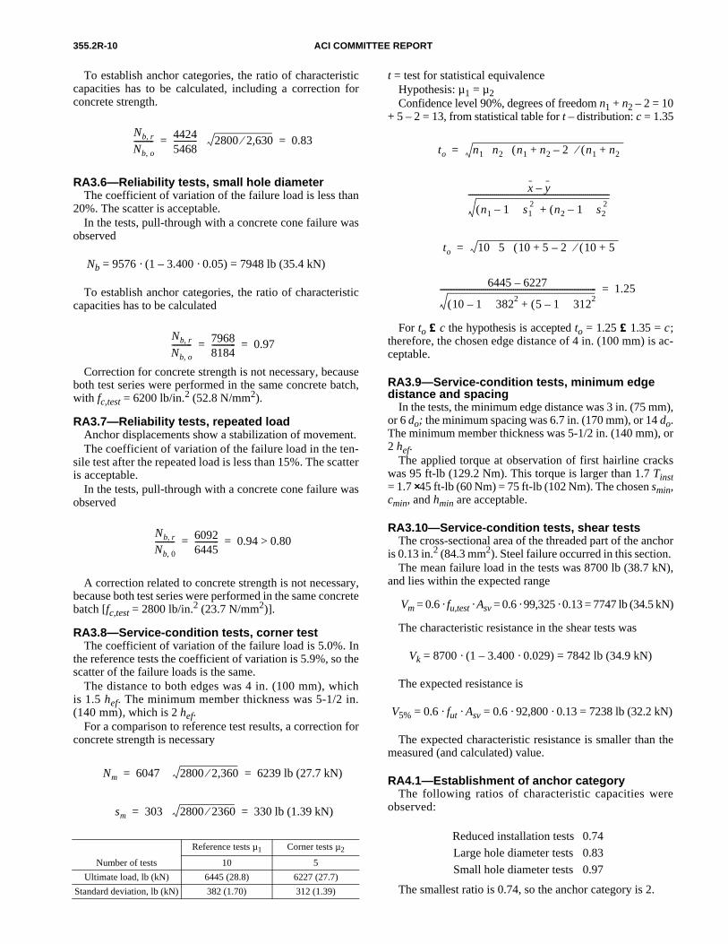
355.2R-10 ACI COMMITTEE REPORT
To establish anchor categories, the ratio of characteristiccapacities has to be calculated, including a correction forconcrete strength.
RA3.6—Reliability tests, small hole diameterThe coefficient of variation of the failure load is less than
20%. The scatter is acceptable.In the tests, pull-through with a concrete cone failure was
observed
Nb = 9576 · (1 – 3.400 · 0.05) = 7948 lb (35.4 kN)
To establish anchor categories, the ratio of characteristiccapacities has to be calculated
Correction for concrete strength is not necessary, becauseboth test series were performed in the same concrete batch,with fc,test = 6200 lb/in.2 (52.8 N/mm2).
RA3.7—Reliability tests, repeated loadAnchor displacements show a stabilization of movement.The coefficient of variation of the failure load in the ten-
sile test after the repeated load is less than 15%. The scatteris acceptable.
In the tests, pull-through with a concrete cone failure wasobserved
A correction related to concrete strength is not necessary,because both test series were performed in the same concretebatch [fc,test = 2800 lb/in.2 (23.7 N/mm2)].
RA3.8—Service-condition tests, corner testThe coefficient of variation of the failure load is 5.0%. In
the reference tests the coefficient of variation is 5.9%, so thescatter of the failure loads is the same.
The distance to both edges was 4 in. (100 mm), whichis 1.5 hef. The minimum member thickness was 5-1/2 in.(140 mm), which is 2 hef.
For a comparison to reference test results, a correction forconcrete strength is necessary
Nb r,
Nb o,---------- 4424
5468------------ 2800 2,630⁄⋅ 0.83= =
Nb r,
Nb o,---------- 7968
8184------------ 0.97= =
Nb r,
Nb 0,---------- 6092
6445------------ 0.94 0.80>= =
Nm 6047 2800 2,360⁄⋅ 6239 lb (27.7 kN)= =
sm 303 2800 2360⁄⋅ 330 lb (1.39 kN)= =
Number of tests
Reference tests µ1 Corner tests µ2
10 5
Ultimate load, lb (kN) 6445 (28.8) 6227 (27.7)
Standard deviation, lb (kN) 382 (1.70) 312 (1.39)
t = test for statistical equivalenceHypothesis: µ1 = µ2Confidence level 90%, degrees of freedom n1 + n2 – 2 = 10
+ 5 – 2 = 13, from statistical table for t – distribution: c = 1.35
For to ≤≤ c the hypothesis is accepted to = 1.25 ≤≤ 1.35 = c;therefore, the chosen edge distance of 4 in. (100 mm) is ac-ceptable.
RA3.9—Service-condition tests, minimum edge distance and spacing
In the tests, the minimum edge distance was 3 in. (75 mm),or 6 do; the minimum spacing was 6.7 in. (170 mm), or 14 do.The minimum member thickness was 5-1/2 in. (140 mm), or2 hef.
The applied torque at observation of first hairline crackswas 95 ft-lb (129.2 Nm). This torque is larger than 1.7 Tinst= 1.7 ⋅⋅ 45 ft-lb (60 Nm) = 75 ft-lb (102 Nm). The chosen smin,cmin, and hmin are acceptable.
RA3.10—Service-condition tests, shear testsThe cross-sectional area of the threaded part of the anchor
is 0.13 in.2 (84.3 mm2). Steel failure occurred in this section. The mean failure load in the tests was 8700 lb (38.7 kN),
and lies within the expected range
Vm = 0.6 · fu,test · Asv = 0.6 · 99,325 · 0.13 = 7747 lb (34.5 kN)
The characteristic resistance in the shear tests was
Vk = 8700 · (1 – 3.400 · 0.029) = 7842 lb (34.9 kN)
The expected resistance is
V5% = 0.6 · fut · Asv = 0.6 · 92,800 · 0.13 = 7238 lb (32.2 kN)
The expected characteristic resistance is smaller than themeasured (and calculated) value.
RA4.1—Establishment of anchor categoryThe following ratios of characteristic capacities were
observed:
The smallest ratio is 0.74, so the anchor category is 2.
Reduced installation tests 0.74
Large hole diameter tests 0.83
Small hole diameter tests 0.97
to n1 n2 n1 n2 2–+( ) n1 n2+( )⁄⋅ ⋅ ⋅=
x y–
n1 1–( ) s12
n2 1–( ) s22⋅+⋅
-----------------------------------------------------------------------
to 10 5 10 5 2–+( ) 10 5+( )⁄⋅ ⋅ ⋅=
6445 6227–
10 1–( ) 3822 5 1–( ) 3122⋅+⋅------------------------------------------------------------------------------- 1.25=

EVALUATING THE PERFORMANCE OF POST-INSTALLED MECHANICAL ANCHORS COMMENTARY 355.2R-11
RA4.2—Report of anchor dataCharacteristic Symbol Dimension Anchor value
Anchor diameter — — 1/2 in. M12
Effective embedment depth hef in. (mm) 2-3/4 (68)
Outside diameter do in. (mm) 1/2 (12)
Effective cross-sectional area—tension Ase in.2 (mm2) 0.09 (58.1)
Effective cross-sectional area—shear Asv in.2 (mm2) 0.13 (84.3)
Minimum specified yield strength fylb/in.2
(N/mm2)74,000 (510)
Minimum specified ultimate strength futlb/in.2
(N/mm2)92,800 (640)
Minimum spacing smin in. (mm) 6.7 (170)
Minimum edge distance cmin in. (mm) 3 (75)
Minimum member thickness hmin in. (mm) 5-1/2 (140)
Category of anchor — — 2
Effectiveness factor k — 22.6 (10)
Characteristic pullout resistance in specified concrete
Np lb/kN 5167 (20.7*)
Anchor axial stiffness in service load range β lb/in.
(kN/mm) 54,970 (14.2)
*Increase characteristic pullout resistance for other specified concrete compressive strength by the square root of the specifiedstrength divided by 2500 lb/in.2 (21 N/mm2).