3529 - pro-flo xt efi ls1 - · pdf filerev. 5/10 - aj/mc table of contents ... please press 1...
TRANSCRIPT
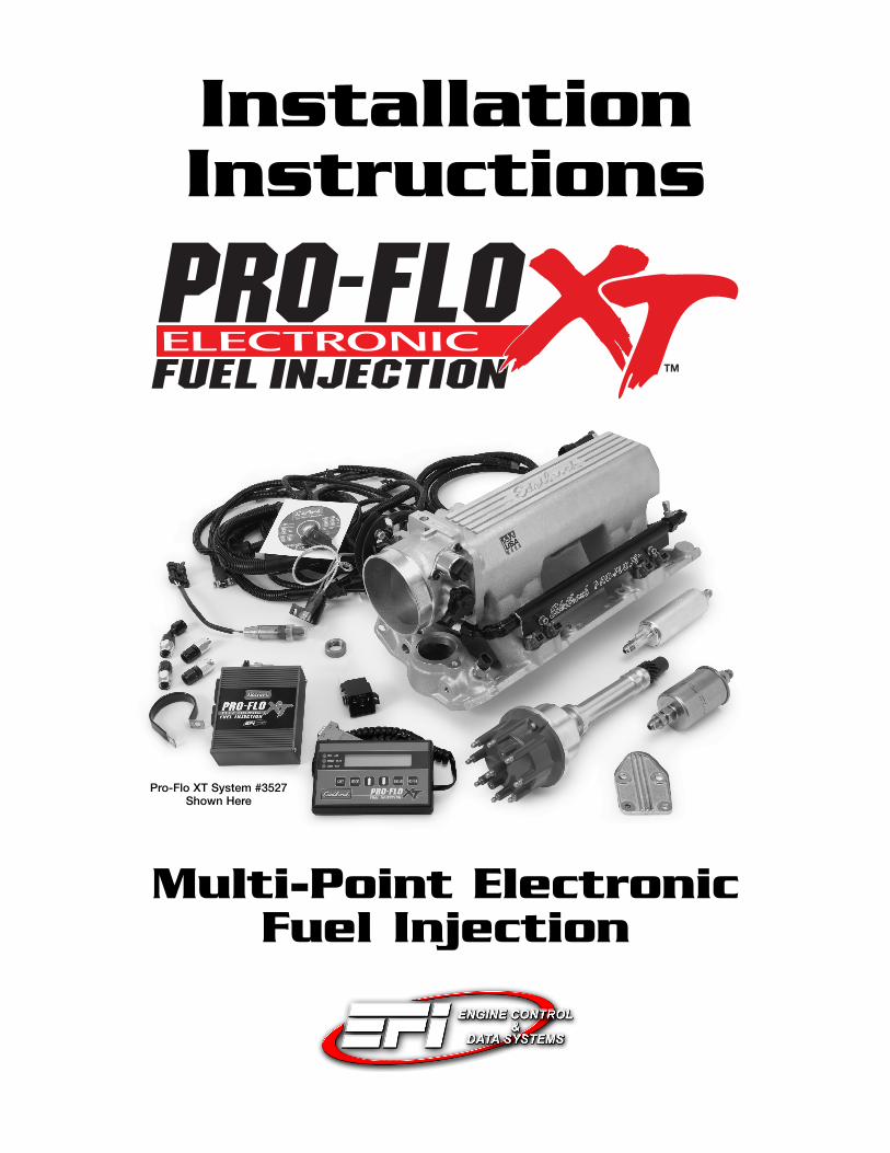
InstallationInstructions
Multi-Point Electronic Fuel Injection
Pro-Flo XT System #3527Shown Here

1Pro-Flo EFI Installation Instructions
©2010 Edelbrock CorporationBrochure No. 63-3529
Part #3529, 3539, 35293 & 35393Rev. 5/10 - AJ/mc
TABLE OF CONTENTSPart #3529, 3539, 35293 & 35393
Introduction.................................................................................................................................................1Components................................................................................................................................................2Preliminaries...............................................................................................................................................3Fuel System................................................................................................................................................6Induction System ......................................................................................................................................10Sensors ....................................................................................................................................................13O2 Sensor Installation ...............................................................................................................................15Main System Harness ...............................................................................................................................16Ignition System .........................................................................................................................................25Other Applications.................................................................................................................................... 26Software Installation .................................................................................................................................28Calibration Selection .................................................................................................................................29System Start-Up........................................................................................................................................30Electronic Engine Management .................................................................................................................33Pro-Flo Quick Tuning Guide.......................................................................................................................34Calibration Module Flowchart ....................................................................................................................36Parts and Part Numbers ............................................................................................................................37Service & Warranty ...................................................................................................................................39
INTRODUCTION
Thank you for selecting the Edelbrock Pro-Flo XT Fuel Injection System. This Multi-Point Fuel Injection System has been designed for GM LS1 &LS6 engines, and is designed to provide excellent performance, fuel economy, and maintenance-free operation. Installation of the Edelbrock Pro-Flo XT Fuel Injection System involves modifications to the fuel system, ignition system, induction system, and possibly the valve train. Althoughthere are steps that must take place before others, the modifications do not necessarily have to be performed in a particular order. Eachmodification is described in a separate section in this manual. Please study these instructions carefully before beginning installation of any partof the Pro-Flo XT system.
If you have any questions, do not hesitate to call our EFI Technical Hotline at (800) 416-8628, 7am-5pm PST, Monday-Friday
(In order to properly relay your call, please press 1 at the prompt to select AutomotiveProducts, followed by 3 to select EFI-Electronics then 1 again for Multi-Point EFI.)
Our EFI Technical Support staff can also be reached via email at: [email protected]
2Pro-Flo EFI Installation Instructions
©2010 Edelbrock CorporationBrochure No. 63-3529
Part #3529, 3539, 35293 & 35393Rev. 5/10 - AJ/mc
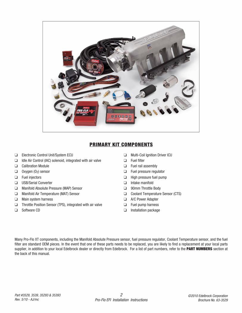
PRIMARY KIT COMPONENTS
❑ Electronic Control Unit/System ECU ❑ Multi-Coil Ignition Driver ICU❑ Idle Air Control (IAC) solenoid, integrated with air valve ❑ Fuel filter❑ Calibration Module ❑ Fuel rail assembly❑ Oxygen (O2) sensor ❑ Fuel pressure regulator
❑ Fuel injectors ❑ High pressure fuel pump❑ USB/Serial Converter ❑ Intake manifold❑ Manifold Absolute Pressure (MAP) Sensor ❑ 90mm Throttle Body❑ Manifold Air Temperature (MAT) Sensor ❑ Coolant Temperature Sensor (CTS)❑ Main system harness ❑ A/C Power Adapter❑ Throttle Position Sensor (TPS), integrated with air valve ❑ Fuel pump harness❑ Software CD ❑ Installation package
Many Pro-Flo XT components, including the Manifold Absolute Pressure sensor, fuel pressure regulator, Coolant Temperature sensor, and the fuelfilter are standard OEM pieces. In the event that one of these parts needs to be replaced, you are likely to find a replacement at your local partssupplier, in addition to your local Edelbrock dealer or directly from Edelbrock. For a list of part numbers, refer to the PART NUMBERS section atthe back of this manual.
3Pro-Flo EFI Installation Instructions
©2010 Edelbrock CorporationBrochure No. 63-3529
Part #3529, 3539, 35293 & 35393Rev. 5/10 - AJ/mc
TOOLS AND EQUIPMENT
Use the following checklist for items needed.❑ Box and open end wrenches
❑ Socket set
❑ Pliers (channel locks and hose clamp)
❑ Screwdrivers (regular and Phillips)
❑ Torque wrench
❑ Hammer
❑ Gasket scraper or putty knife
❑ Timing light
❑ Vacuum gauge
❑ Rags
❑ Water bucket
❑ Drill and bits
❑ Hole saw (1 1/4-inch or 1 3/4-inch)
❑ Tubing wrenches
❑ Tubing cutter
PRELIMINARY CHECKLIST
1. CAREFULLY STUDY AND UNDERSTAND ALL INSTRUCTIONS, BEFORE BEGINNING THIS INSTALLATION.
NOTE: This installation can be accomplished using common tools and procedures. However, you should have a basic
knowledge of automotive repair and modification and be familiar with and comfortable working on your vehicle. If you do
not feel comfortable working on your vehicle, it is recommended to have the installation completed by a professional
mechanic.
2. Examine the Pro-Flo XT system for possible shipping damage. If damaged, contact your dealer immediately.
3. The 3529 kit is designed for use with the stock LS Chevy V8 firing order (1-8-7-2-6-5-4-3).
4. Check all threaded manifold holes.
5. Check all internal manifold passages with a light and wire, making sure they are clean and unobstructed.
6. Check automatic transmission shift points before removal of your stock manifold and adjust linkage after Edelbrock
manifold installation for same shift points (if needed).
NOTE:: We recommend that you refer to this checklist again after installation to be sure that you have completed all steps.
HARDWARE AND PARTS RECOMMENDED
Use the following checklist for items needed.❑ OEM o-ring intake gaskets; GM #12533587
❑ Pipe plugs, if needed
❑ 5/16-inch steel tubing (approximate equal length to fuel pickup
line in tank)
❑ Loctite 598 OEM High Temperature Silicone Gasket (O2 Sensor
Compatible)
❑ Radiator coolant
❑ Wiring diagram for your vehicle
❑ Teflon tape or liquid Teflon thread sealer
❑ 195° Thermostat
❑ Resistor type spark plugs (Use correct heat range for your
particular application)
❑ Set of low-resistance spark plug wires with high EMI suppression
(DO NOT use solid core spark plug wires)
❑ Dynojet wideband commander (Optional, not included)
❑ DB9 Serial extension cable (Optional, not included)
4Pro-Flo EFI Installation Instructions
©2010 Edelbrock CorporationBrochure No. 63-3529
Part #3529, 3539, 35293 & 35393Rev. 5/10 - AJ/mc
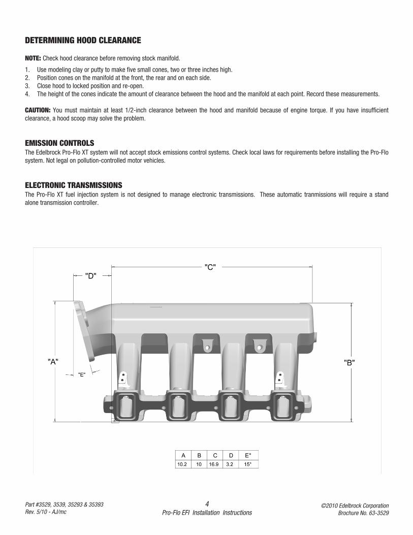
DETERMINING HOOD CLEARANCE
NOTE: Check hood clearance before removing stock manifold.
1. Use modeling clay or putty to make five small cones, two or three inches high.2. Position cones on the manifold at the front, the rear and on each side.3. Close hood to locked position and re-open.4. The height of the cones indicate the amount of clearance between the hood and the manifold at each point. Record these measurements.
CAUTION: You must maintain at least 1/2-inch clearance between the hood and manifold because of engine torque. If you have insufficientclearance, a hood scoop may solve the problem.
EMISSION CONTROLSThe Edelbrock Pro-Flo XT system will not accept stock emissions control systems. Check local laws for requirements before installing the Pro-Flosystem. Not legal on pollution-controlled motor vehicles.
ELECTRONIC TRANSMISSIONSThe Pro-Flo XT fuel injection system is not designed to manage electronic transmissions. These automatic tranmissions will require a standalone transmission controller.
5Pro-Flo EFI Installation Instructions
©2010 Edelbrock CorporationBrochure No. 63-3529
Part #3529, 3539, 35293 & 35393Rev. 5/10 - AJ/mc
FUEL REQUIREMENTSBecause the Pro-Flo XT system uses an Oxygen sensor, you should use unleaded fuel only. Leaded fuels will shorten the life of the O2 sensor.
AUTOMATIC TRANSMISSION CHECK
For best performance, economy, and emissions, the shift point must be checked before and after the manifold change.
NOTE: This check should be performed ONLY at a sanctioned drag strip or test track.
With the shifter in Drive, accelerate to wide open throttle from a standing start. Hold in this position, noting speedometer MPH when thetransmission makes the first 1-2 shift. After the Pro-Flo XT system has been installed, make the same test, again noting MPH of this first shift.
The transmissions in certain vehicles require precise adjustments. We recommend that you consult a reputable transmission shop for finaladjustments once the Pro-Flo system has been installed. Incorrect shift points can result in transmission damage.
ENGINE CLEANINGEdelbrock recommends that the Pro-Flo XT system be installed on a clean engine in order to prevent dirt from falling into the intake ports.
1. Cover ignition. Use engine degreaser and a brush to thoroughly clean the manifold and the area between the manifold and valve covers.
2. Rinse with water and blow dry.
HEADERSFor best performance, headers are recommended. For this application, header primary tube diameter should be 1-3/4 inch, approximately 31inches long and terminating into a 3 inch collector. The remainder of the exhaust system should consist of dual exhaust and tail pipes, at least 2-1/4 inches in diameter with low back pressure mufflers.
COOLING SYSTEMThe minimum requirements for the thermostat are 180° but the ideal thermostat is 195°. When the vehicle is at 175 or below, system will stayin cold start mode and not perform properly.
6Pro-Flo EFI Installation Instructions
©2010 Edelbrock CorporationBrochure No. 63-3529
Part #3529, 3539, 35293 & 35393Rev. 5/10 - AJ/mc
FUEL SYSTEM
Pro-Flo XT electronic fuel injection requires high and constant fuel volume and fuel pressure. For this reason, a good primary fuel line is critical.The Pro-Flo XT system includes a 3/8-inch high pressure fuel line which must be used as the primary fuel line. The fuel that bypasses theinjectors must be returned to the fuel tank via a return fuel line. If your vehicle is already equipped with a fuel pump bypass line, this line can beused as the return fuel line. If not, the original primary line may be used as the return line. If desired, a 15 foot length of 3/8” ID Pro Classic hoseis supplied for use as the return line.
Many late-model cars are equipped with an additional fuel line which runs to a charcoal canister mounted on the driver side of the vehicle. Thisline MUST be re-installed after the fuel system conversion and MUST NOT be used as the return fuel line.
Tank Side
Engine Side
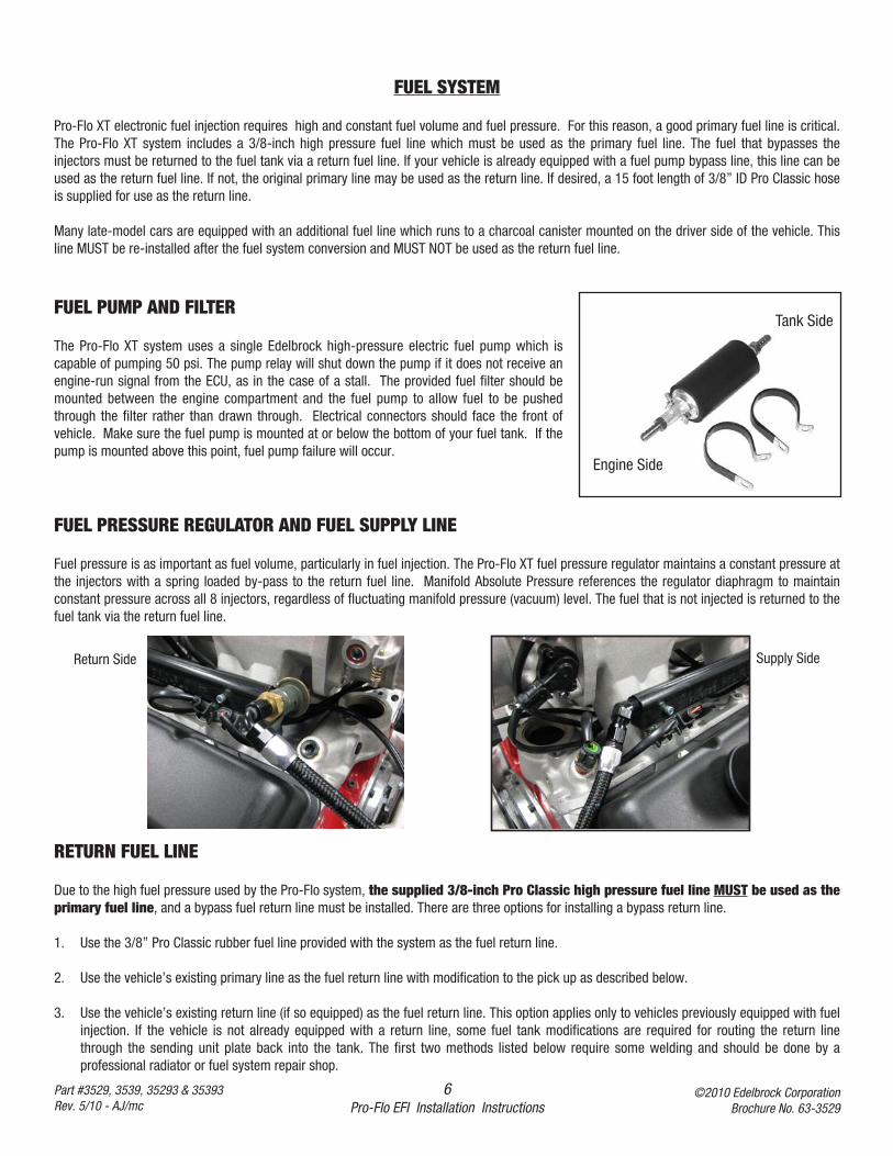
FUEL PUMP AND FILTER
The Pro-Flo XT system uses a single Edelbrock high-pressure electric fuel pump which iscapable of pumping 50 psi. The pump relay will shut down the pump if it does not receive anengine-run signal from the ECU, as in the case of a stall. The provided fuel filter should bemounted between the engine compartment and the fuel pump to allow fuel to be pushedthrough the filter rather than drawn through. Electrical connectors should face the front ofvehicle. Make sure the fuel pump is mounted at or below the bottom of your fuel tank. If thepump is mounted above this point, fuel pump failure will occur.
FUEL PRESSURE REGULATOR AND FUEL SUPPLY LINE
Fuel pressure is as important as fuel volume, particularly in fuel injection. The Pro-Flo XT fuel pressure regulator maintains a constant pressure atthe injectors with a spring loaded by-pass to the return fuel line. Manifold Absolute Pressure references the regulator diaphragm to maintainconstant pressure across all 8 injectors, regardless of fluctuating manifold pressure (vacuum) level. The fuel that is not injected is returned to thefuel tank via the return fuel line.
RETURN FUEL LINE
Due to the high fuel pressure used by the Pro-Flo system, the supplied 3/8-inch Pro Classic high pressure fuel line MUST be used as theprimary fuel line, and a bypass fuel return line must be installed. There are three options for installing a bypass return line.
1. Use the 3/8” Pro Classic rubber fuel line provided with the system as the fuel return line.
2. Use the vehicle’s existing primary line as the fuel return line with modification to the pick up as described below.
3. Use the vehicle’s existing return line (if so equipped) as the fuel return line. This option applies only to vehicles previously equipped with fuelinjection. If the vehicle is not already equipped with a return line, some fuel tank modifications are required for routing the return linethrough the sending unit plate back into the tank. The first two methods listed below require some welding and should be done by aprofessional radiator or fuel system repair shop.
Return Side Supply Side
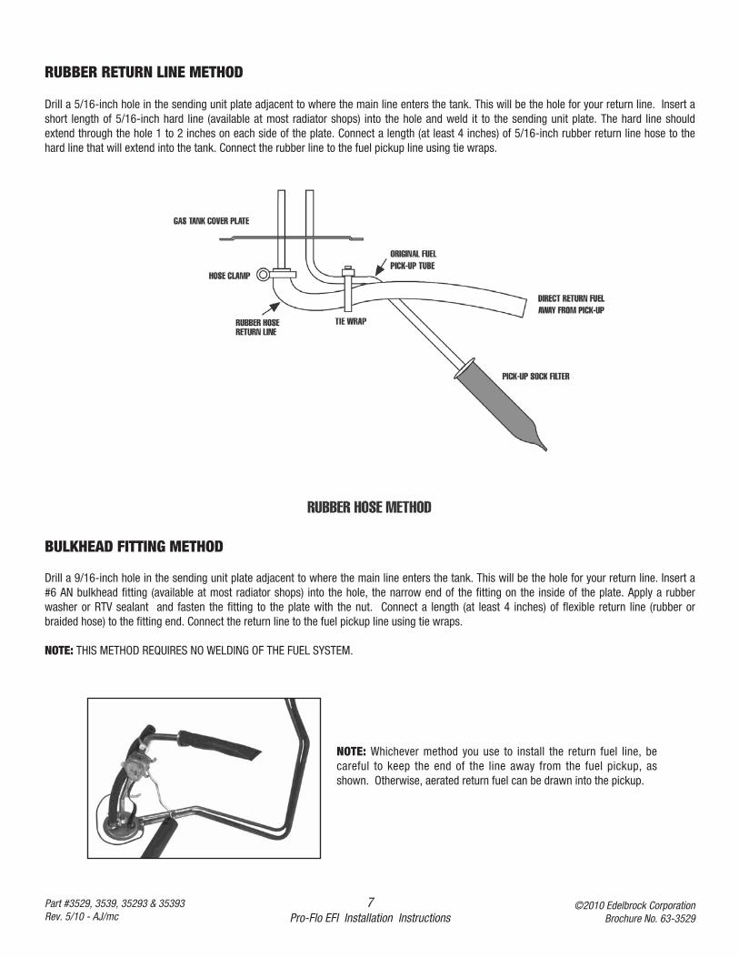
RUBBER RETURN LINE METHOD
Drill a 5/16-inch hole in the sending unit plate adjacent to where the main line enters the tank. This will be the hole for your return line. Insert ashort length of 5/16-inch hard line (available at most radiator shops) into the hole and weld it to the sending unit plate. The hard line shouldextend through the hole 1 to 2 inches on each side of the plate. Connect a length (at least 4 inches) of 5/16-inch rubber return line hose to thehard line that will extend into the tank. Connect the rubber line to the fuel pickup line using tie wraps.
7Pro-Flo EFI Installation Instructions
©2010 Edelbrock CorporationBrochure No. 63-3529
Part #3529, 3539, 35293 & 35393Rev. 5/10 - AJ/mc
BULKHEAD FITTING METHOD
Drill a 9/16-inch hole in the sending unit plate adjacent to where the main line enters the tank. This will be the hole for your return line. Insert a#6 AN bulkhead fitting (available at most radiator shops) into the hole, the narrow end of the fitting on the inside of the plate. Apply a rubberwasher or RTV sealant and fasten the fitting to the plate with the nut. Connect a length (at least 4 inches) of flexible return line (rubber orbraided hose) to the fitting end. Connect the return line to the fuel pickup line using tie wraps.
NOTE: THIS METHOD REQUIRES NO WELDING OF THE FUEL SYSTEM.
NOTE: Whichever method you use to install the return fuel line, becareful to keep the end of the line away from the fuel pickup, asshown. Otherwise, aerated return fuel can be drawn into the pickup.
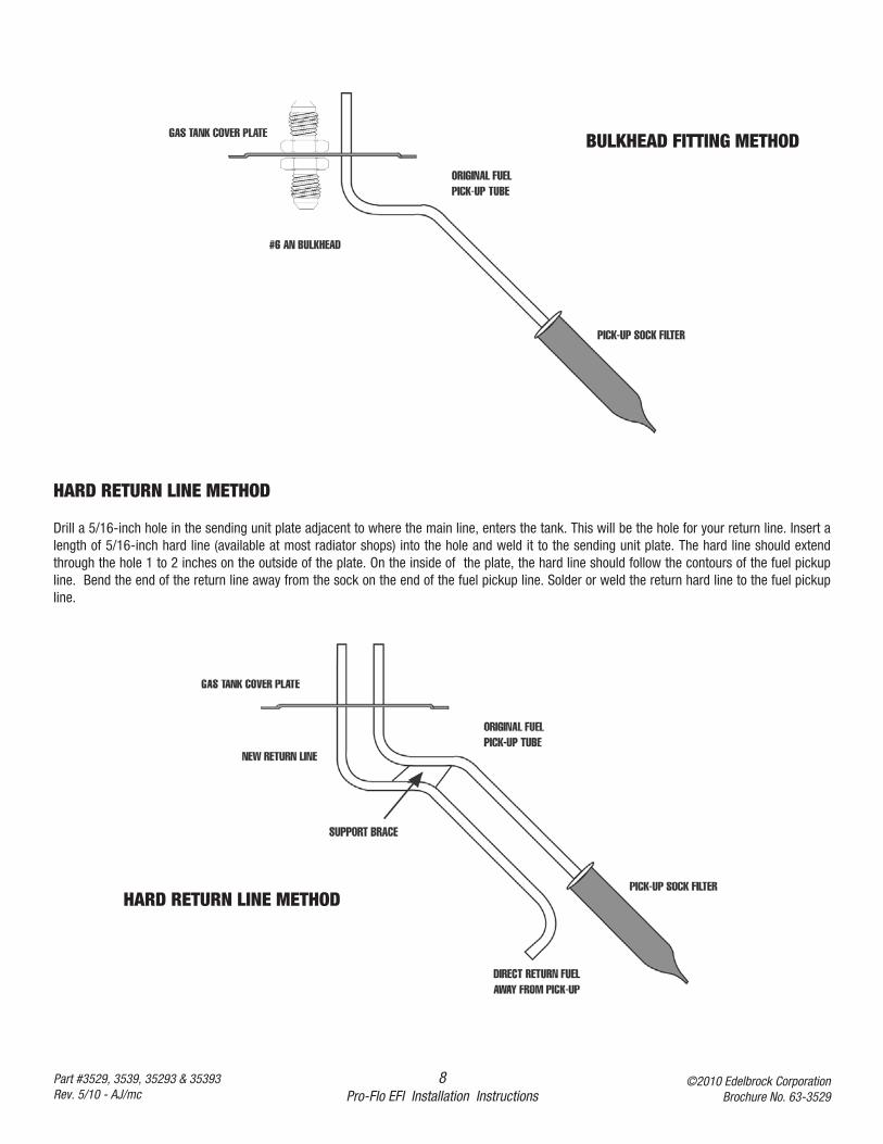
HARD RETURN LINE METHOD
Drill a 5/16-inch hole in the sending unit plate adjacent to where the main line, enters the tank. This will be the hole for your return line. Insert alength of 5/16-inch hard line (available at most radiator shops) into the hole and weld it to the sending unit plate. The hard line should extendthrough the hole 1 to 2 inches on the outside of the plate. On the inside of the plate, the hard line should follow the contours of the fuel pickupline. Bend the end of the return line away from the sock on the end of the fuel pickup line. Solder or weld the return hard line to the fuel pickupline.
8Pro-Flo EFI Installation Instructions
©2010 Edelbrock CorporationBrochure No. 63-3529
Part #3529, 3539, 35293 & 35393Rev. 5/10 - AJ/mc
BULKHEAD FITTING METHOD
HARD RETURN LINE METHOD
9Pro-Flo EFI Installation Instructions
©2010 Edelbrock CorporationBrochure No. 63-3529
Part #3529, 3539, 35293 & 35393Rev. 5/10 - AJ/mc
NOTE: ALL WELDING AND SOLDERING OF THE FUEL SYSTEM MUST BE PERFORMED BY APROFESSIONAL RADIATOR AND/OR FUEL SYSTEM REPAIR SHOP.
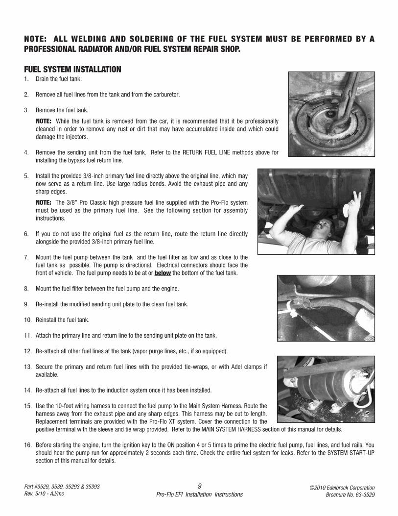
FUEL SYSTEM INSTALLATION1. Drain the fuel tank.
2. Remove all fuel lines from the tank and from the carburetor.
3. Remove the fuel tank.
NOTE: While the fuel tank is removed from the car, it is recommended that it be professionallycleaned in order to remove any rust or dirt that may have accumulated inside and which coulddamage the injectors.
4. Remove the sending unit from the fuel tank. Refer to the RETURN FUEL LINE methods above forinstalling the bypass fuel return line.
5. Install the provided 3/8-inch primary fuel line directly above the original line, which maynow serve as a return line. Use large radius bends. Avoid the exhaust pipe and anysharp edges.
NOTE: The 3/8” Pro Classic high pressure fuel line supplied with the Pro-Flo systemmust be used as the primary fuel line. See the following section for assemblyinstructions.
6. If you do not use the original fuel as the return line, route the return line directlyalongside the provided 3/8-inch primary fuel line.
7. Mount the fuel pump between the tank and the fuel filter as low and as close to thefuel tank as possible. The pump is directional. Electrical connectors should face thefront of vehicle. The fuel pump needs to be at or below the bottom of the fuel tank.
8. Mount the fuel filter between the fuel pump and the engine.
9. Re-install the modified sending unit plate to the clean fuel tank.
10. Reinstall the fuel tank.
11. Attach the primary line and return line to the sending unit plate on the tank.
12. Re-attach all other fuel lines at the tank (vapor purge lines, etc., if so equipped).
13. Secure the primary and return fuel lines with the provided tie-wraps, or with Adel clamps ifavailable.
14. Re-attach all fuel lines to the induction system once it has been installed.
15. Use the 10-foot wiring harness to connect the fuel pump to the Main System Harness. Route theharness away from the exhaust pipe and any sharp edges. This harness may be cut to length.Replacement terminals are provided with the Pro-Flo XT system. Cover the connection to thepositive terminal with the sleeve and tie wrap provided. Refer to the MAIN SYSTEM HARNESS section of this manual for details.
16. Before starting the engine, turn the ignition key to the ON position 4 or 5 times to prime the electric fuel pump, fuel lines, and fuel rails. Youshould hear the pump run for approximately 2 seconds each time. Check the entire fuel system for leaks. Refer to the SYSTEM START-UPsection of this manual for details.
10Pro-Flo EFI Installation Instructions
©2010 Edelbrock CorporationBrochure No. 63-3529
Part #3529, 3539, 35293 & 35393Rev. 5/10 - AJ/mc
INDUCTION SYSTEM
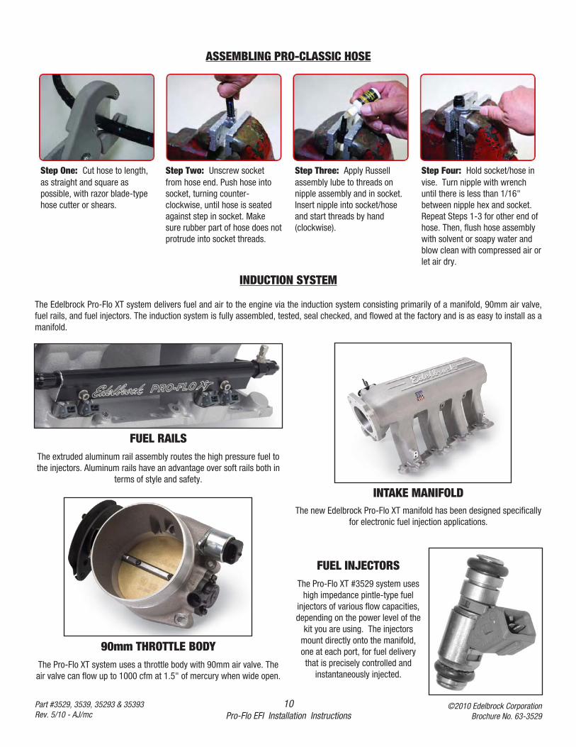
The Edelbrock Pro-Flo XT system delivers fuel and air to the engine via the induction system consisting primarily of a manifold, 90mm air valve,fuel rails, and fuel injectors. The induction system is fully assembled, tested, seal checked, and flowed at the factory and is as easy to install as amanifold.
INTAKE MANIFOLDThe new Edelbrock Pro-Flo XT manifold has been designed specifically
for electronic fuel injection applications.
90mm THROTTLE BODYThe Pro-Flo XT system uses a throttle body with 90mm air valve. Theair valve can flow up to 1000 cfm at 1.5" of mercury when wide open.
FUEL INJECTORSThe Pro-Flo XT #3529 system uses
high impedance pintle-type fuelinjectors of various flow capacities,depending on the power level of the
kit you are using. The injectorsmount directly onto the manifold,one at each port, for fuel deliverythat is precisely controlled and
instantaneously injected.
FUEL RAILSThe extruded aluminum rail assembly routes the high pressure fuel tothe injectors. Aluminum rails have an advantage over soft rails both in
terms of style and safety.
ASSEMBLING PRO-CLASSIC HOSE
Step One: Cut hose to length,as straight and square aspossible, with razor blade-typehose cutter or shears.
Step Two: Unscrew socketfrom hose end. Push hose intosocket, turning counter-clockwise, until hose is seatedagainst step in socket. Makesure rubber part of hose does notprotrude into socket threads.
Step Three: Apply Russellassembly lube to threads onnipple assembly and in socket.Insert nipple into socket/hoseand start threads by hand(clockwise).
Step Four: Hold socket/hose invise. Turn nipple with wrenchuntil there is less than 1/16"between nipple hex and socket.Repeat Steps 1-3 for other end ofhose. Then, flush hose assemblywith solvent or soapy water andblow clean with compressed air orlet air dry.
11Pro-Flo EFI Installation Instructions
©2010 Edelbrock CorporationBrochure No. 63-3529
Part #3529, 3539, 35293 & 35393Rev. 5/10 - AJ/mc
PRE-INSTALLATION
Before installing the induction system, take the following steps to ensure successful installation and performance
1. Check all components thoroughly for damage.2. Make sure all throttle linkages open entirely and close freely.3. Make sure all fuel inlet and vacuum ports are free from packing material.4. Check the installation kit for proper parts.
REMOVING THE STOCK THROTTLE BODY AND MANIFOLD
1. Disconnect battery.2. For ease of installation, keep all parts in order.
CAUTION: Do not remove manifold if engine is hot.3. Remove gas cap to relieve pressure. Disconnect fuel line and plug. Replace gas cap.4. Disconnect all linkage from throttle body such as the throttle cable, throttle springs, transmission, cruise control and automatic choke.5. Remove all brackets from the manifold.
PORT SURFACE CLEANING
When cleaning old gaskets from head surfaces, lay rags in the lifter valley and stuff paper into the ports, to prevent pieces of the old gasket fromfalling into ports and combustion chambers. When clean, remove paper, making sure that all particles fall on the rags in the lifter valley. Removerags, and wipe surfaces clean with rags soaked in lacquer thinner in order to remove oil or grease. NOTE: This procedure is necessary to ensureproper sealing.
INSTALLING FITTINGS, PIPE PLUGS, AND STUDS
Do not over-tighten or cross-thread fittings, pipe plugs, studs, or bolts in your aluminum manifold. Damage to threads or a cracked mountingboss may result unless caution is used when installing accessories.
Use high quality pipe thread sealant on all threads. Install fittings from your stock manifold.
12Pro-Flo EFI Installation Instructions
©2010 Edelbrock CorporationBrochure No. 63-3529
Part #3529, 3539, 35293 & 35393Rev. 5/10 - AJ/mc
GASKET SURFACE PREPARATION
CAUTION: The Pro-Flo XT LS manifold has been designed to work with factory o-ring style intake gaskets. These can be ordered from any GMdealership as GM part #12533587. Use of any other gaskets may cause vacuum leaks and/or engine damage.
Check manifold flange grooves to make sure the gaskets are positioned correctly. Make sure the tabs line up with the notches and that theo-rings do not kink in their grooves.
INDUCTION SYSTEM INSTALLATION
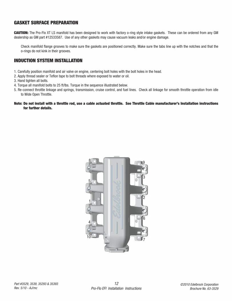
1. Carefully position manifold and air valve on engine, centering bolt holes with the bolt holes in the head.2. Apply thread sealer or Teflon tape to bolt threads where exposed to water or oil.3. Hand tighten all bolts.4. Torque all manifold bolts to 25 ft/lbs. Torque in the sequence illustrated below.5. Re-connect throttle linkage and springs, transmission, cruise control, and fuel lines. Check all linkage for smooth throttle operation from idle
to Wide Open Throttle.
Note: Do not install with a throttle rod, use a cable actuated throttle. See Throttle Cable manufacturer’s Installation instructionsfor further details.
3
7
8 9
10
6
5
4
12
13Pro-Flo EFI Installation Instructions
©2010 Edelbrock CorporationBrochure No. 63-3529
Part #3529, 3539, 35293 & 35393Rev. 5/10 - AJ/mc
SENSORS
The Edelbrock Pro-Flo XT system interprets overall engine operating conditions and fuel/spark requirements based on readings from sensors thatmeasure specific engine conditions.
The Pro-Flo system includes five sensors:
1) Manifold Absolute Pressure (MAP)2) Manifold Air Temperature (MAT)3) Coolant Temperature (ECT)4) Throttle Position (TPS)5) Exhaust Oxygen (O2)
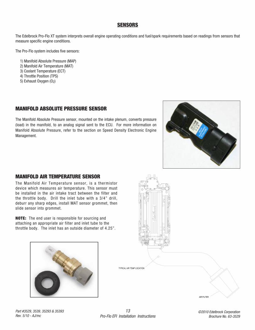
MANIFOLD ABSOLUTE PRESSURE SENSOR
The Manifold Absolute Pressure sensor, mounted on the intake plenum, converts pressure(load) in the manifold, to an analog signal sent to the ECU. For more information onManifold Absolute Pressure, refer to the section on Speed Density Electronic EngineManagement.
MANIFOLD AIR TEMPERATURE SENSORThe Manifold Air Temperature sensor, is a thermistordevice which measures air temperature. This sensor mustbe installed in the air intake tract between the filter andthe throttle body. Drill the inlet tube with a 3/4” drill,deburr any sharp edges, install MAT sensor grommet, thenslide sensor into grommet.
NOTE: The end user is responsible for sourcing andattaching an appropriate air filter and inlet tube to thethrottle body. The inlet has an outside diameter of 4.25”.
14Pro-Flo EFI Installation Instructions
©2010 Edelbrock CorporationBrochure No. 63-3529
Part #3529, 3539, 35293 & 35393Rev. 5/10 - AJ/mc
OXYGEN (O2) SENSOR
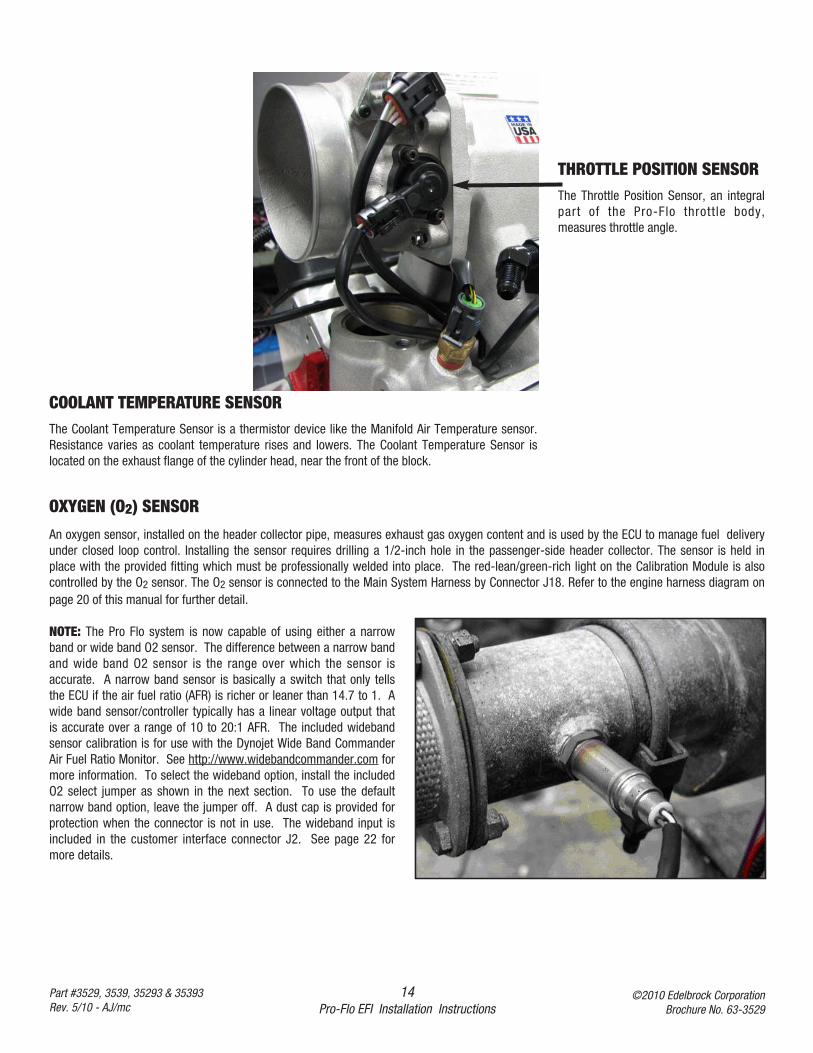
An oxygen sensor, installed on the header collector pipe, measures exhaust gas oxygen content and is used by the ECU to manage fuel deliveryunder closed loop control. Installing the sensor requires drilling a 1/2-inch hole in the passenger-side header collector. The sensor is held inplace with the provided fitting which must be professionally welded into place. The red-lean/green-rich light on the Calibration Module is alsocontrolled by the O2 sensor. The O2 sensor is connected to the Main System Harness by Connector J18. Refer to the engine harness diagram onpage 20 of this manual for further detail.
NOTE: The Pro Flo system is now capable of using either a narrowband or wide band O2 sensor. The difference between a narrow bandand wide band O2 sensor is the range over which the sensor isaccurate. A narrow band sensor is basically a switch that only tellsthe ECU if the air fuel ratio (AFR) is richer or leaner than 14.7 to 1. Awide band sensor/controller typically has a linear voltage output thatis accurate over a range of 10 to 20:1 AFR. The included widebandsensor calibration is for use with the Dynojet Wide Band CommanderAir Fuel Ratio Monitor. See http://www.widebandcommander.com formore information. To select the wideband option, install the includedO2 select jumper as shown in the next section. To use the defaultnarrow band option, leave the jumper off. A dust cap is provided forprotection when the connector is not in use. The wideband input isincluded in the customer interface connector J2. See page 22 formore details.
THROTTLE POSITION SENSORThe Throttle Position Sensor, an integralpart of the Pro-Flo throttle body,measures throttle angle.
COOLANT TEMPERATURE SENSORThe Coolant Temperature Sensor is a thermistor device like the Manifold Air Temperature sensor.Resistance varies as coolant temperature rises and lowers. The Coolant Temperature Sensor islocated on the exhaust flange of the cylinder head, near the front of the block.
15Pro-Flo EFI Installation Instructions
©2010 Edelbrock CorporationBrochure No. 63-3529
Part #3529, 3539, 35293 & 35393Rev. 5/10 - AJ/mc
O2 SENSOR INSTALLATIONThe exhaust gas oxygen content is determined by the oxygen sensor. The sensor signals the ECU, which compensates when the air/fuel mixtureis either rich or lean.
NOTE: It is recommended that the O2 sensor installation be performed by a professional muffler shop.
1. Double check header gaskets, replacing if necessary.
2. Drill a 1/2-inch to 9/16-inch hole in the passenger-side header collector reducer, as close to the header flange as possible. (1" to 3" away)
NOTE: Before drilling, make sure the O2 sensor will be mounted horizontally and within reach of the harness connector. Check to ensureadequate clearance for the sensor, taking into consideration engine movement.
3. Fit the provided fitting into the hole in the exhaust pipe and weld into place.
4. Once it has been welded into place, clean the threads in the center of the fitting.
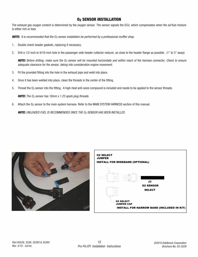
5. Thread the O2 sensor into the fitting. A high-heat anti-seize compound is included and needs to be applied to the sensor threads.
NOTE: The O2 sensor has 18mm x 1.25 spark plug threads.
6. Attach the O2 sensor to the main system harness. Refer to the MAIN SYSTEM HARNESS section of this manual.
NOTE: UNLEADED FUEL IS RECOMMENDED ONCE THE O2 SENSOR HAS BEEN INSTALLED.
O2 SELECTJUMPER
O2 SELECTJUMPER CAP
SELECT
J3O2 SENSOR
INSTALL FOR WIDEBAND (OPTIONAL)
INSTALL FOR NARROW BAND (INCLUDED IN KIT)
16Pro-Flo EFI Installation Instructions
©2010 Edelbrock CorporationBrochure No. 63-3529
Part #3529, 3539, 35293 & 35393Rev. 5/10 - AJ/mc
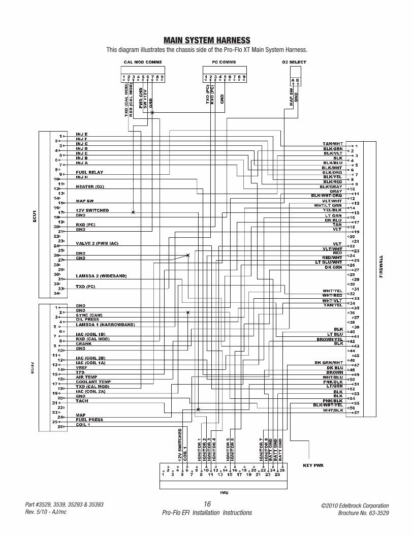
MAIN SYSTEM HARNESSThis diagram illustrates the chassis side of the Pro-Flo XT Main System Harness.
17Pro-Flo EFI Installation Instructions
©2010 Edelbrock CorporationBrochure No. 63-3529
Part #3529, 3539, 35293 & 35393Rev. 5/10 - AJ/mc
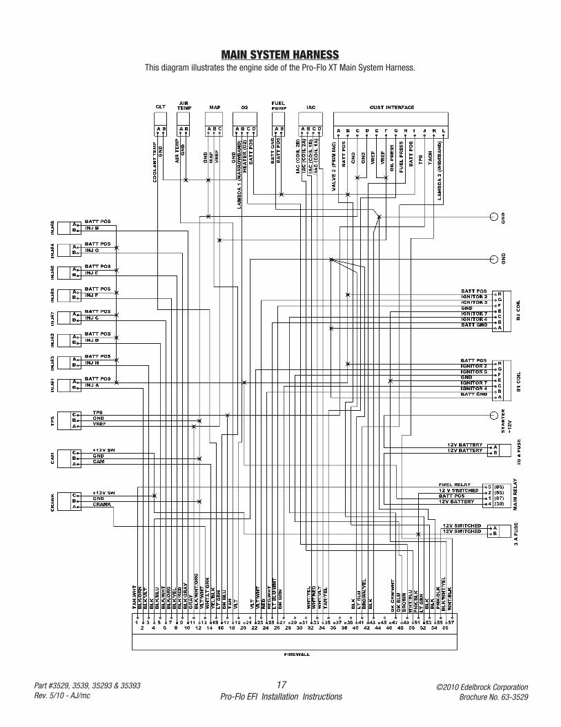
MAIN SYSTEM HARNESSThis diagram illustrates the engine side of the Pro-Flo XT Main System Harness.
18Pro-Flo EFI Installation Instructions
©2010 Edelbrock CorporationBrochure No. 63-3529
Part #3529, 3539, 35293 & 35393Rev. 5/10 - AJ/mc
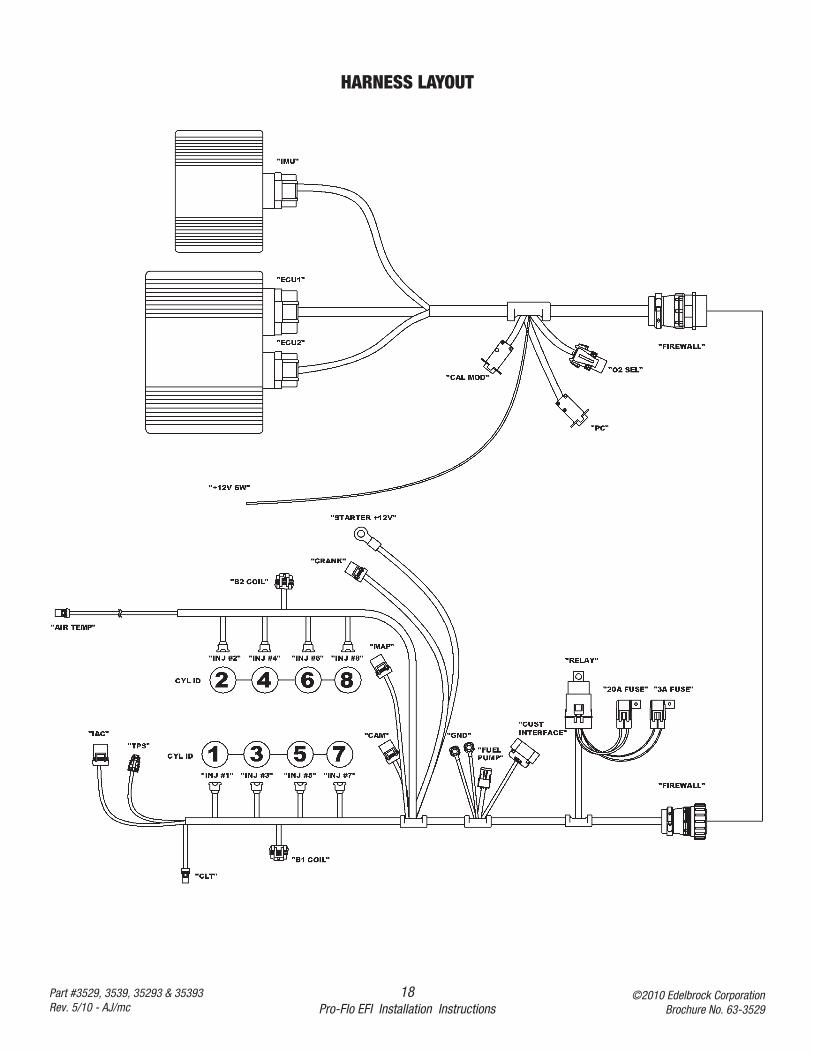
HARNESS LAYOUT
19Pro-Flo EFI Installation Instructions
©2010 Edelbrock CorporationBrochure No. 63-3529
Part #3529, 3539, 35293 & 35393Rev. 5/10 - AJ/mc
INSTALLATION
The Pro-Flo XT Main Harness is divided into two pieces, the engine harness and chassis harness. A bulkhead connector is provided as a passthrough firewall connector.
1. Inspect the Main System Harness, making sure that all connectors and grounds are properly in place.
2. Edelbrock strongly recommends mounting the Pro-Flo XT ECU in the passenger compartment to protect it from possible damage. A 37-pinbulkhead connector has been supplied to simplify wire routing. Mounting this connector will require drilling an 1-1/2” hole in the firewall,along with four 3/16” holes for the mounting bolts (Tekscrews are supplied in the kit for this purpose).
NOTE: The harness ends include strain relief collars that extend several inches from the bulkhead connector. Verify that sufficientclearance from any exhaust piping or other hardware is available BEFORE drilling.
NOTE: Start the screw holes with a pointed punch or small drill.
3. Mount the plate so that the large coarse threads protrude through the hole in the firewall into the engine compartment. The squaremounting pad should be on the engine side of the firewall. Use RTV to seal the plate to the firewall.
4. The engine harness was designed to be routed underneath the plenum area of the Pro Flo XT intake manifold. See photos and diagrams foradditional information.
5. The heavy ground lug with black wires should be bolted to the rear of the cylinder head. Be sure the connection is clean with without anycorrosion. The heavy power lug with the orange wire should be connected to an uniterrupted +12v source such as the positive terminal onthe starter solenoid.
6. The pink wire with a black stripe should be connected to a switched +12v power source. It should be hot in both the start and run positions.See the photos and diagrams that appear elsewhere in this manual for further details.
OTHER APPLICATIONS
The Pro-Flo XT system has been designed and calibrated specifically using the GM LS1 small block with large-valve style cylinder heads (such asEdelbrock’s Performer RPM XTreme Street Cylinder Heads with 2.02-inch valves) and tubular headers as a baseline.
It is unlikely that every engine on which the Pro-Flo XT system is installed will match this baseline combination. The system can be used withsimilar applications, as long as the necessary fuel calibration adjustments are made. If your engine does not have headers, or uses small-valvestyle cylinder heads (such as stock OEM heads), it may require additional tuning adjustments.
If you are running small-valve heads and/or you are not using tubular headers, it may be necessary to adjust the air/fuel ratio at WOT from 4000rpm and up. Refer to the table below for starting points for adjustments. Use the FUEL @ WOT screens (located under FUEL MODIFIERS) toadjust the fuel at each available RPM.
WARNING: Watch the Rich/Lean light on the Calibration Module. If the light indicates a lean condition (red) for more than a fraction of a second at06” vacuum or WOT you are too lean for safe engine operation at full load.
IGNITION SYSTEM
The photo on the opposite page shows how the ICU, ECU, ignition harness and Main System Harness are connected.
A KEY ON wire (Pink with black stripe) is also included in the Pro-Flo system. This wire connects to a reliable switched +12v source. Make surethere is power with the key on and also while cranking.
REFER TO VEHICLE REPAIR MANUAL FOR WIRING DIAGRAM, IF NECESSARY.
20Pro-Flo EFI Installation Instructions
©2010 Edelbrock CorporationBrochure No. 63-3529
Part #3529, 3539, 35293 & 35393Rev. 5/10 - AJ/mc
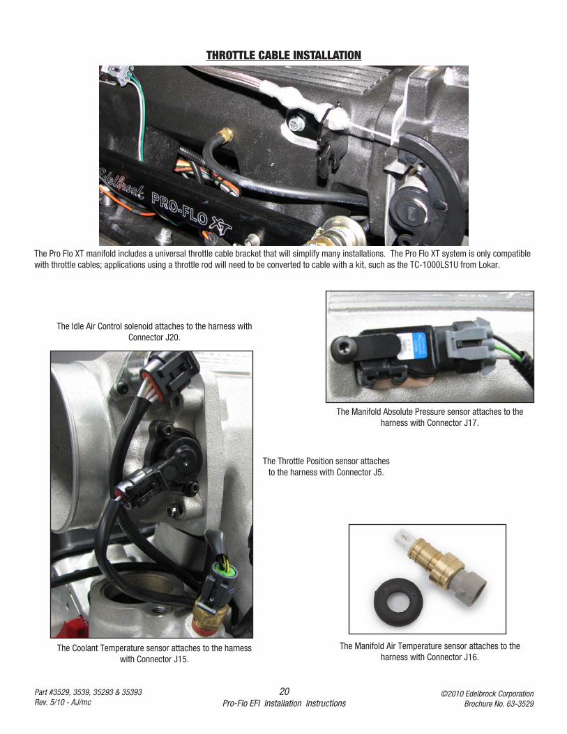
The Coolant Temperature sensor attaches to the harnesswith Connector J15.
The Manifold Absolute Pressure sensor attaches to theharness with Connector J17.
The Manifold Air Temperature sensor attaches to theharness with Connector J16.
The Throttle Position sensor attachesto the harness with Connector J5.
The Idle Air Control solenoid attaches to the harness withConnector J20.
THROTTLE CABLE INSTALLATION
The Pro Flo XT manifold includes a universal throttle cable bracket that will simplify many installations. The Pro Flo XT system is only compatiblewith throttle cables; applications using a throttle rod will need to be converted to cable with a kit, such as the TC-1000LS1U from Lokar.
21Pro-Flo EFI Installation Instructions
©2010 Edelbrock CorporationBrochure No. 63-3529
Part #3529, 3539, 35293 & 35393Rev. 5/10 - AJ/mc
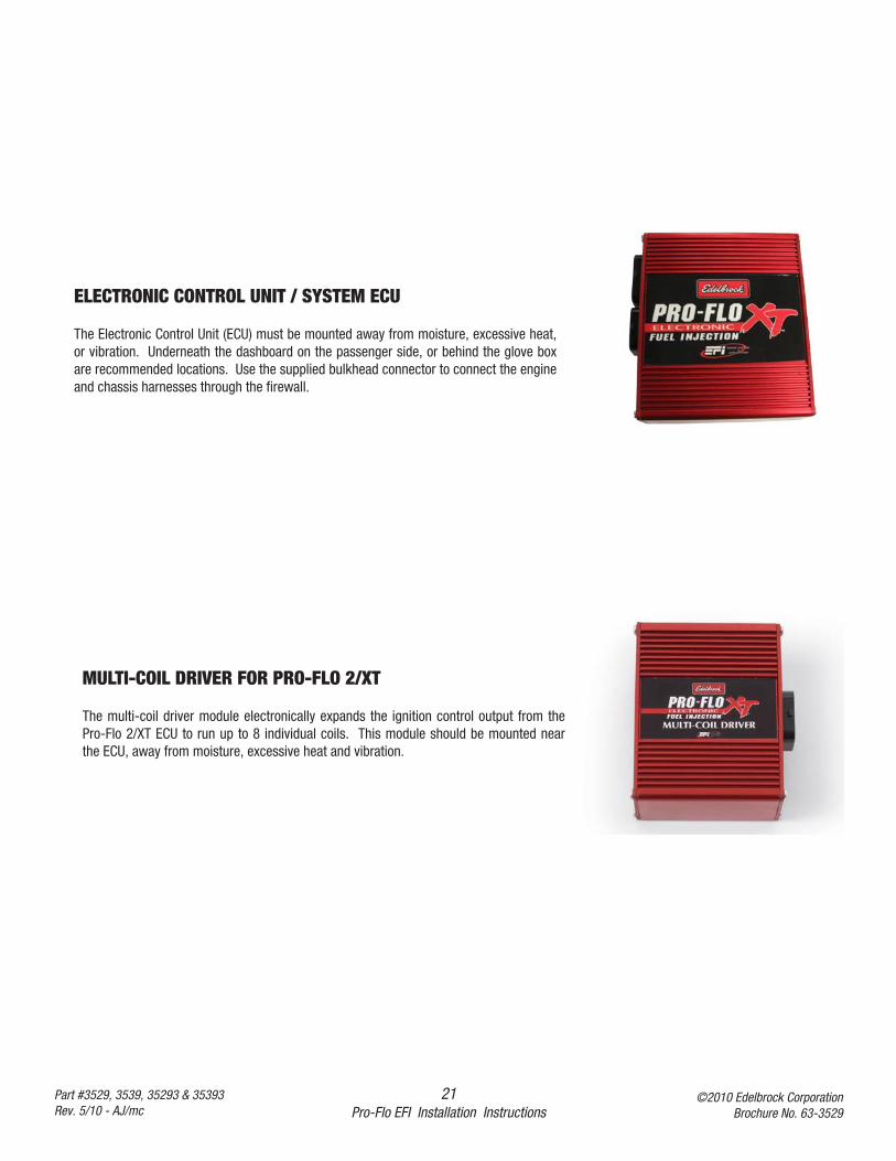
ELECTRONIC CONTROL UNIT / SYSTEM ECU
The Electronic Control Unit (ECU) must be mounted away from moisture, excessive heat,or vibration. Underneath the dashboard on the passenger side, or behind the glove boxare recommended locations. Use the supplied bulkhead connector to connect the engineand chassis harnesses through the firewall.
MULTI-COIL DRIVER FOR PRO-FLO 2/XT
The multi-coil driver module electronically expands the ignition control output from thePro-Flo 2/XT ECU to run up to 8 individual coils. This module should be mounted nearthe ECU, away from moisture, excessive heat and vibration.
22Pro-Flo EFI Installation Instructions
©2010 Edelbrock CorporationBrochure No. 63-3529
Part #3529, 3539, 35293 & 35393Rev. 5/10 - AJ/mc
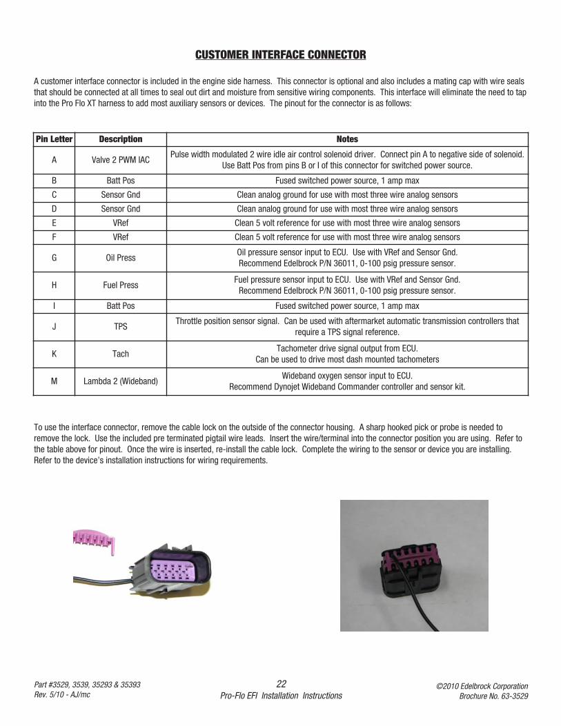
CUSTOMER INTERFACE CONNECTOR
A customer interface connector is included in the engine side harness. This connector is optional and also includes a mating cap with wire sealsthat should be connected at all times to seal out dirt and moisture from sensitive wiring components. This interface will eliminate the need to tapinto the Pro Flo XT harness to add most auxiliary sensors or devices. The pinout for the connector is as follows:
Pin Letter Description Notes
A Valve 2 PWM IACPulse width modulated 2 wire idle air control solenoid driver. Connect pin A to negative side of solenoid.
Use Batt Pos from pins B or I of this connector for switched power source.
B Batt Pos Fused switched power source, 1 amp max
C Sensor Gnd Clean analog ground for use with most three wire analog sensors
D Sensor Gnd Clean analog ground for use with most three wire analog sensors
E VRef Clean 5 volt reference for use with most three wire analog sensors
F VRef Clean 5 volt reference for use with most three wire analog sensors
G Oil PressOil pressure sensor input to ECU. Use with VRef and Sensor Gnd.Recommend Edelbrock P/N 36011, 0-100 psig pressure sensor.
H Fuel PressFuel pressure sensor input to ECU. Use with VRef and Sensor Gnd.
Recommend Edelbrock P/N 36011, 0-100 psig pressure sensor.
I Batt Pos Fused switched power source, 1 amp max
J TPSThrottle position sensor signal. Can be used with aftermarket automatic transmission controllers that
require a TPS signal reference.
K TachTachometer drive signal output from ECU.
Can be used to drive most dash mounted tachometers
M Lambda 2 (Wideband)Wideband oxygen sensor input to ECU.
Recommend Dynojet Wideband Commander controller and sensor kit.
To use the interface connector, remove the cable lock on the outside of the connector housing. A sharp hooked pick or probe is needed toremove the lock. Use the included pre terminated pigtail wire leads. Insert the wire/terminal into the connector position you are using. Refer tothe table above for pinout. Once the wire is inserted, re-install the cable lock. Complete the wiring to the sensor or device you are installing.Refer to the device’s installation instructions for wiring requirements.
23Pro-Flo EFI Installation Instructions
©2010 Edelbrock CorporationBrochure No. 63-3529
Part #3529, 3539, 35293 & 35393Rev. 5/10 - AJ/mc
To connect the ECU to your PC, plug the 34 pin ECU connector into the ECU. The connector will only plug in one way. Connect the DB9 serialconnector to your PC either directly or through an extension cable (not included). Plug the AC Power Adapter into a standard wall socket.
NOTE: A USB to Serial converter is included with the kit to be used if your PC does not have a 9 pin serial port. Connect the USB end of theadapter to your PC and the serial port (9 pin) end to the power adapter harness. Follow the instructions included with the USB adapter as well ason the CD to install the appropriate drivers. Go to File - Port Settings in eFlash and select the com port that matches the location of the adapter.
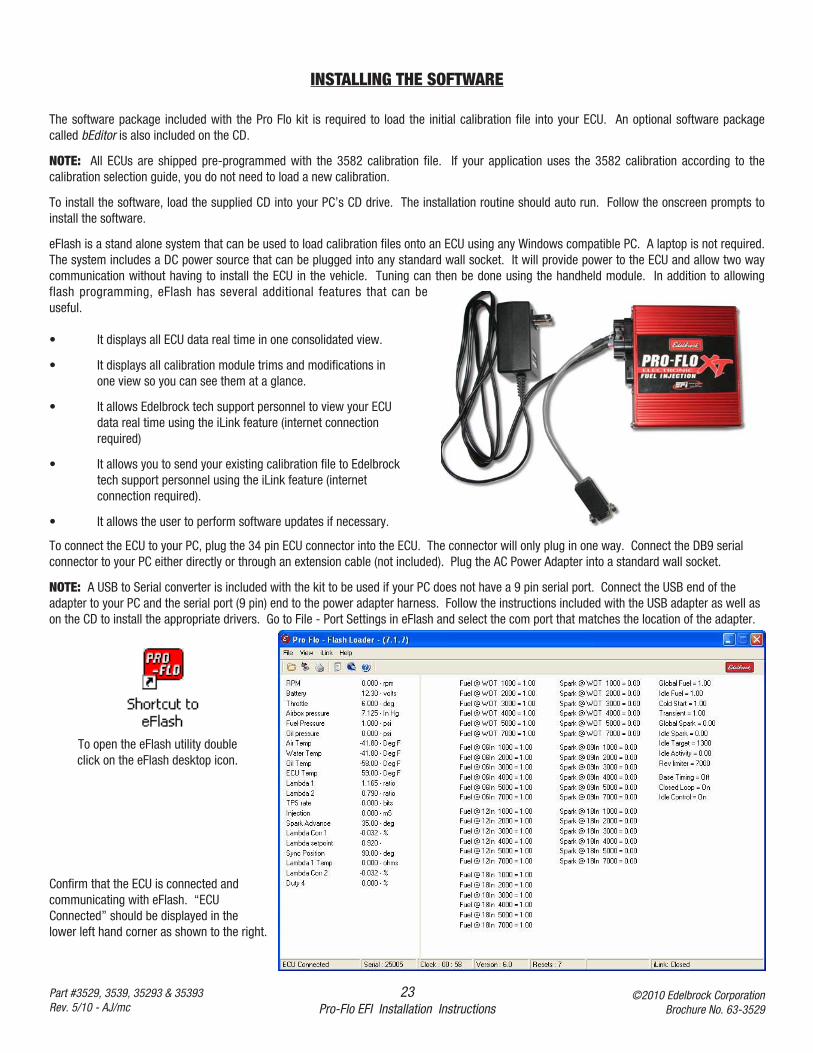
Confirm that the ECU is connected andcommunicating with eFlash. “ECUConnected” should be displayed in thelower left hand corner as shown to the right.
INSTALLING THE SOFTWARE
The software package included with the Pro Flo kit is required to load the initial calibration file into your ECU. An optional software packagecalled bEditor is also included on the CD.
NOTE: All ECUs are shipped pre-programmed with the 3582 calibration file. If your application uses the 3582 calibration according to thecalibration selection guide, you do not need to load a new calibration.
To install the software, load the supplied CD into your PC’s CD drive. The installation routine should auto run. Follow the onscreen prompts toinstall the software.
eFlash is a stand alone system that can be used to load calibration files onto an ECU using any Windows compatible PC. A laptop is not required.The system includes a DC power source that can be plugged into any standard wall socket. It will provide power to the ECU and allow two waycommunication without having to install the ECU in the vehicle. Tuning can then be done using the handheld module. In addition to allowingflash programming, eFlash has several additional features that can beuseful.
• It displays all ECU data real time in one consolidated view.
• It displays all calibration module trims and modifications in one view so you can see them at a glance.
• It allows Edelbrock tech support personnel to view your ECU data real time using the iLink feature (internet connection required)
• It allows you to send your existing calibration file to Edelbrock tech support personnel using the iLink feature (internet connection required).
• It allows the user to perform software updates if necessary.
To open the eFlash utility doubleclick on the eFlash desktop icon.
24Pro-Flo EFI Installation Instructions
©2010 Edelbrock CorporationBrochure No. 63-3529
Part #3529, 3539, 35293 & 35393Rev. 5/10 - AJ/mc
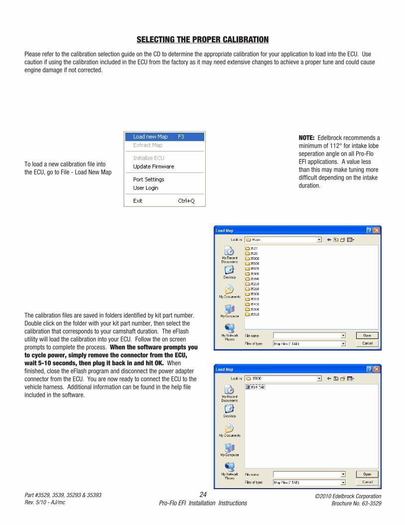
SELECTING THE PROPER CALIBRATION
To load a new calibration file intothe ECU, go to File - Load New Map
NOTE: Edelbrock recommends aminimum of 112° for intake lobeseperation angle on all Pro-FloEFI applications. A value lessthan this may make tuning moredifficult depending on the intakeduration.
The calibration files are saved in folders identified by kit part number.Double click on the folder with your kit part number, then select thecalibration that corresponds to your camshaft duration. The eFlashutility will load the calibration into your ECU. Follow the on screenprompts to complete the process. When the software prompts youto cycle power, simply remove the connector from the ECU,wait 5-10 seconds, then plug it back in and hit OK. Whenfinished, close the eFlash program and disconnect the power adapterconnector from the ECU. You are now ready to connect the ECU to thevehicle harness. Additional information can be found in the help fileincluded in the software.
Please refer to the calibration selection guide on the CD to determine the appropriate calibration for your application to load into the ECU. Usecaution if using the calibration included in the ECU from the factory as it may need extensive changes to achieve a proper tune and could causeengine damage if not corrected.
25Pro-Flo EFI Installation Instructions
©2010 Edelbrock CorporationBrochure No. 63-3529
Part #3529, 3539, 35293 & 35393Rev. 5/10 - AJ/mc
Priming The Fuel PumpBefore the engine is started, the fuel pump must be primed to pressurize the system and purge the fuel line of all air.
1. Turn ignition key to the ON position. You should hear the fuel pump go on. It will pump for 2 or 3 seconds and disengage.2. Turn the key to the OFF position for 1 second.3. Turn the key to the ON position again. The pump will go on for another 2 or 3 seconds.4. Repeat this procedure until the pump has been cycled three or four times, and is primed. The tone of the fuel pump will change when all air
is out of the fuel system.5. If there is no tone, or no change in tone, the system is not priming. Check the entire fuel system for leaks, from the fuel tank to the injectors.
Testing The SensorsBefore starting the engine, test all sensors.
1. Turn the key to the ON position with the Calibration Module connected. The display will read:
NOTE: A vacuum reading of other than 0.0” Hg may be displayed depending upon barometric pressure and air temperature. At extremealtitude, the vacuum reading may be as high as 5.0” Hg.
2. Push the UP ARROW key once to display.
NOTE: The water and air temperatures displayed will vary depending on ambient conditions. The system voltage will vary depending on thecondition of the battery.
3. Move the throttle to test the Throttle Position Sensor (TPS). The TPS reading should vary depending on throttle angle.
4. If the calibration module goes blank while cranking, the system is losing power. Check the Pink/Black wire attached to the 3 Amp fuse for+12V power with the ignition in the crank position and the run position for proper operation.
RPM: 0 FUEL: 0.0 mSVAC: 0.0” Hg SPK: 10°
TH2O: 76°F TPS: 13°TAIR: 77°F Volt: 12.0
SYSTEM START-UP
Once the Edelbrock Pro-Flo system has been installed, there are a few procedures you must follow to break-in the system. Carefully performingthese break-in procedures will ensure best results and optimal performance.
Use this checklist to double-check the following areas BEFORE starting the car:
❑ Has the battery been reconnected?❑ Has the radiator been refilled with coolant?❑ Has the gas tank been refilled?❑ Has the oil been replaced?❑ Have all linkages been reconnected?❑ Have all wiring harness connectors been connected?❑ Have all fuel lines been reconnected?❑ Has the exhaust system been completely re-installed?❑ Has the O2 sensor been installed and connected?
❑ Have resistor type spark plugs been installed?❑ Has the calibration module been connected to the main harness?
26Pro-Flo EFI Installation Instructions
©2010 Edelbrock CorporationBrochure No. 63-3529
Part #3529, 3539, 35293 & 35393Rev. 5/10 - AJ/mc
Idle AdjustmentThis procedure is a general recommendation, intended to help you fine tune your Pro-Flo® system.
NOTE: This procedure should be followed with the car in Neutral and the brake pedal pressed.
Idle Calibration Procedure• Prior to idle calibration, you need to have completed the "System Start-Up" procedure • Warm up the engine to at least 175°F. • Using the calibration module, Select MISC. MODIFIERS and Set Idle Control OFF. • Check the idle speed, and adjust your throttle blades to achieve the desired speed, if necessary.• Note the VAC value on the calibration module.• Go to Fuel Modifiers and find the RPM and VAC setting closest to your current Idle RPM and VAC readings.• Slowly add or subtract fuel until you get the best idle quality.• Readjust the idle speed with the blade adjustment screw until the desired idle RPM is achieved.• Note the VAC value on the calibration module once again.• Go to Spark Modifiers and find the RPM and VAC settings closest to your current Idle RPM and VAC readings.• Slowly add or subtract spark until you get the best idle quality.• Readjust the idle speed with the blade adjustment screw to desired idle speed, if necessary.• Turn Idle Control back on. There should be very little, if any, change to the idle speed with Idle Control ON or OFF at idle, in neutral.• Save changes to Position A in the calibration module.NOTE: You must save your changes before turning the ignition ON/OFF. If they are not saved, they will be erased when you restart.
Idle TroubleshootingVehicles equipped with an automatic transmission should now be able to shift into Drive, with the brake still depressed, and see a slight dip inengine rpm followed by a resumption of the idle speed set in the procedure above. If any surging or an erratic idle occurs, follow the stepsbelow:• Note the lowest RPM during the surging and the average VAC readings.• Shift the transmission into neutral.• Use the Calibration Module to turn off Closed Loop Control.• Go into the Fuel Modifiers and find the RPM and VAC settings closest to the values noted above.• Add 5% fuel.• Put the transmission back into Drive and see if the surging has gotten better or worse.• Go back and add or subtract fuel until you get the highest VAC and a stable idle.• When you are satisfied with the results, turn closed loop back ON and save changes to position A again.
Idle Tuning Tips • The ECU always starts in position A. you must save the changes to position A for them to do anything. You can save your current tune
into B or C and restore them if you want. They will restore to A.• You should never have big jumps in the Fuel or Spark modifiers from one location to the next. If you have 10% in one location the
surrounding locations should not very more than an additional 10%.• Only use the Idle fuel and spark settings once you have the regular Fuel and Spark Modifiers where the engine runs the best.• Closed loop control does not work at Idle.
Save Calibration • Using the calibration module, Select MISC. MODIFIERS • Set IDLE CONTROL ON. Set TARGET IDLE to the same RPM established by the idle stop screw. • Save calibration settings to “A”
27Pro-Flo EFI Installation Instructions
©2010 Edelbrock CorporationBrochure No. 63-3529
Part #3529, 3539, 35293 & 35393Rev. 5/10 - AJ/mc
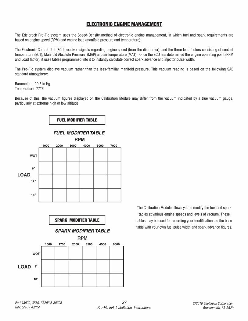
ELECTRONIC ENGINE MANAGEMENT
The Edelbrock Pro-Flo system uses the Speed-Density method of electronic engine management, in which fuel and spark requirements arebased on engine speed (RPM) and engine load (manifold pressure and temperature).
The Electronic Control Unit (ECU) receives signals regarding engine speed (from the distributor), and the three load factors consisting of coolanttemperature (ECT), Manifold Absolute Pressure (MAP) and air temperature (MAT). Once the ECU has determined the engine operating point (RPMand Load factor), it uses tables programmed into it to instantly calculate correct spark advance and injector pulse width.
The Pro-Flo system displays vacuum rather than the less-familiar manifold pressure. This vacuum reading is based on the following SAEstandard atmosphere:
Barometer 29.5 in HgTemperature 77°F
Because of this, the vacuum figures displayed on the Calibration Module may differ from the vacuum indicated by a true vacuum gauge,particularly at extreme high or low altitude.
The Calibration Module allows you to modify the fuel and spark
tables at various engine speeds and levels of vacuum. These
tables may be used for recording your modifications to the base
table with your own fuel pulse width and spark advance figures.
FUEL MODIFIER TABLE
SPARK MODIFIER TABLE
28Pro-Flo EFI Installation Instructions
©2010 Edelbrock CorporationBrochure No. 63-3529
Part #3529, 3539, 35293 & 35393Rev. 5/10 - AJ/mc
PRO-FLO QUICK TUNING GUIDE
This guide is based on our simple graph that shows the 24 fuel cells that you can tune in to result in a clean and powerful engine. Werecommend when you have your Pro-Flo installed, you have the idle tune up completed and then drive the vehicle to determine what amount oftuning is needed for general driving. If the unit is driveable, this is the method to use for ease of tuning. On page 33 of this installation manual,there is a fuel grid that can be used as the map on which to locate and then tune any drivability problems. Simply drive the vehicle and note anyareas that have problems. Circle those areas as a baseline.
When circling the area where a problem exists, you are circling the RPM and Vacuum reading that is present when the problem occurs.Note whether it is running rich (green light) or lean (red light) at each problem area. Once any problem areas have been located and noted rich orlean, go into the Miscellaneous Modifiers menu and turn off the Closed Loop Fuel, exit, go to Fuel Modifiers, and then into Global Fuel. Now drivethe vehicle and drive back to each problem area. When driving in a problem area, add or subtract fuel to obtain the smoothest operation at thatdriving point. Write down the quantity (plus or minus) of fuel required to achieve a smooth operation. When all the problem areas have beennoted, and the amount of fuel required to achieve smooth operation has been noted at each problem area, you may now do each adjustment oneat a time to achieve a complete tune up.
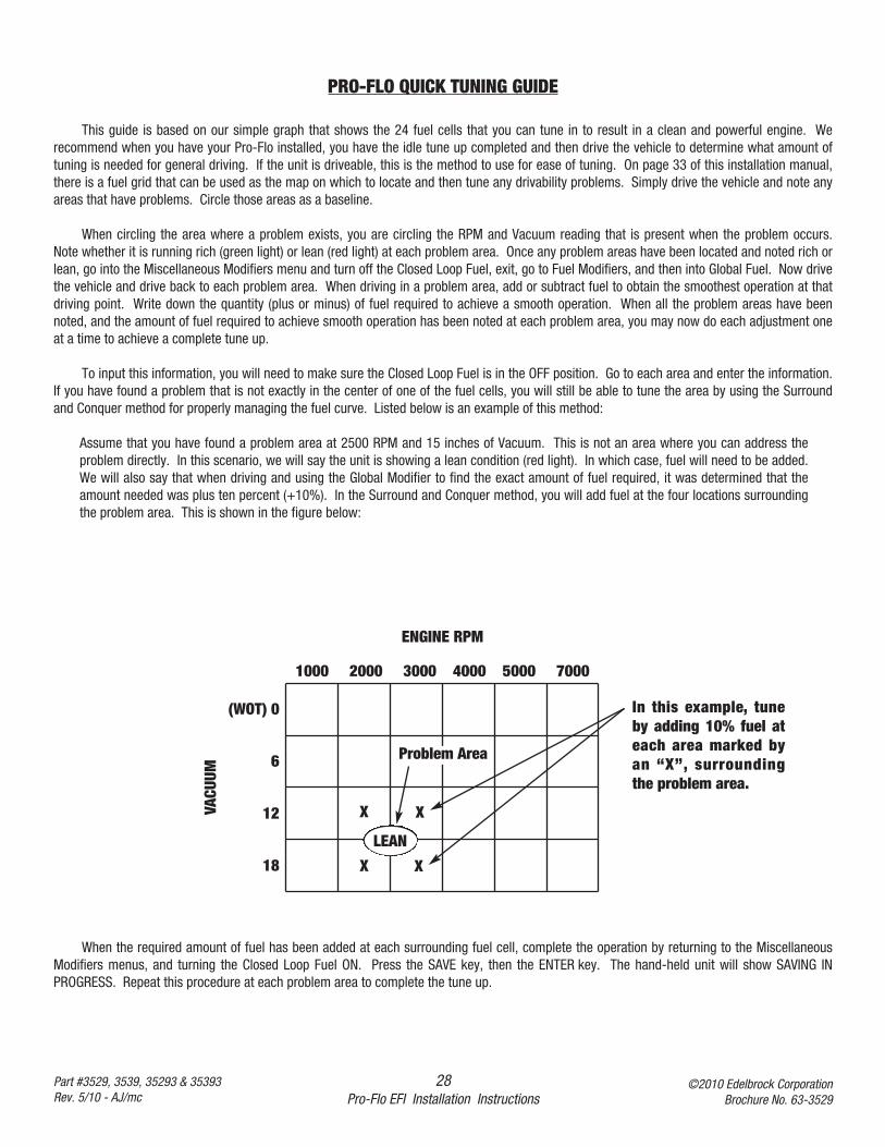
To input this information, you will need to make sure the Closed Loop Fuel is in the OFF position. Go to each area and enter the information.If you have found a problem that is not exactly in the center of one of the fuel cells, you will still be able to tune the area by using the Surroundand Conquer method for properly managing the fuel curve. Listed below is an example of this method:
Assume that you have found a problem area at 2500 RPM and 15 inches of Vacuum. This is not an area where you can address theproblem directly. In this scenario, we will say the unit is showing a lean condition (red light). In which case, fuel will need to be added.We will also say that when driving and using the Global Modifier to find the exact amount of fuel required, it was determined that theamount needed was plus ten percent (+10%). In the Surround and Conquer method, you will add fuel at the four locations surroundingthe problem area. This is shown in the figure below:
1000 2000 3000 4000 5000 7000
(WOT) 0
6
12
18
LEAN
VACU
UM
ENGINE RPM
XX
XX
Problem Area
In this example, tuneby adding 10% fuel ateach area marked byan “X”, surroundingthe problem area.
When the required amount of fuel has been added at each surrounding fuel cell, complete the operation by returning to the MiscellaneousModifiers menus, and turning the Closed Loop Fuel ON. Press the SAVE key, then the ENTER key. The hand-held unit will show SAVING INPROGRESS. Repeat this procedure at each problem area to complete the tune up.
29Pro-Flo EFI Installation Instructions
©2010 Edelbrock CorporationBrochure No. 63-3529
Part #3529, 3539, 35293 & 35393Rev. 5/10 - AJ/mc
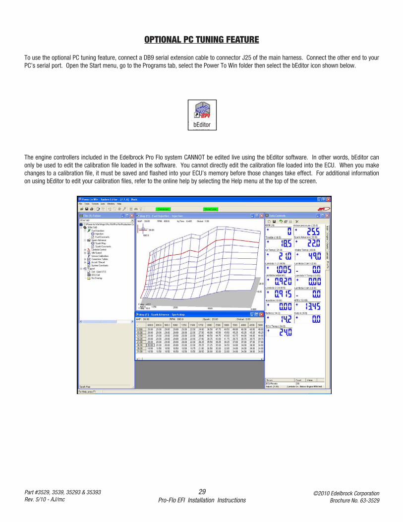
OPTIONAL PC TUNING FEATURE
To use the optional PC tuning feature, connect a DB9 serial extension cable to connector J25 of the main harness. Connect the other end to yourPC’s serial port. Open the Start menu, go to the Programs tab, select the Power To Win folder then select the bEditor icon shown below.
The engine controllers included in the Edelbrock Pro Flo system CANNOT be edited live using the bEditor software. In other words, bEditor canonly be used to edit the calibration file loaded in the software. You cannot directly edit the calibration file loaded into the ECU. When you makechanges to a calibration file, it must be saved and flashed into your ECU’s memory before those changes take effect. For additional informationon using bEditor to edit your calibration files, refer to the online help by selecting the Help menu at the top of the screen.
bEditor
30Pro-Flo EFI Installation Instructions
©2010 Edelbrock CorporationBrochure No. 63-3529
Part #3529, 3539, 35293 & 35393Rev. 5/10 - AJ/mc
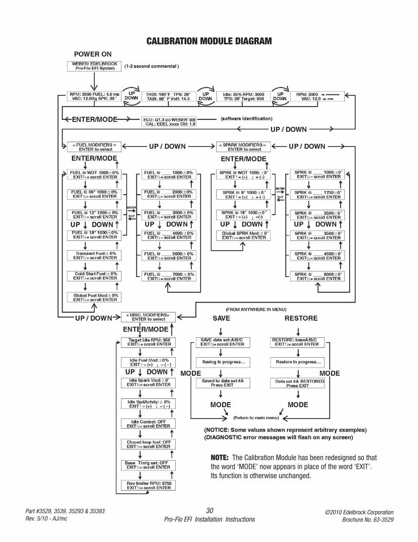
CALIBRATION MODULE DIAGRAM
NOTE: The Calibration Module has been redesigned so thatthe word ‘MODE’ now appears in place of the word ‘EXIT’.Its function is otherwise unchanged.
31Pro-Flo EFI Installation Instructions
©2010 Edelbrock CorporationBrochure No. 63-3529
Part #3529, 3539, 35293 & 35393Rev. 5/10 - AJ/mc
PART NUMBERS
Edelbrock Pro-Flo
Fuel Injection System..........................................................................................Edelbrock #3529ECU power relay/Fuel pump relay .......................................................................Edelbrock #3586Manifold Absolute Pressure sensor....................................................................Edelbrock #36019
GM 12569240Manifold Air Temperature sensor (Push-In) .........................................................Edelbrock #3578
AC12160244Coolant Temperature sensor .............................................................................Edelbrock #36012
GM 25036979Throttle Position sensor ......................................................................................Edelbrock #3590Oxygen (O2) sensor ...........................................................................................Edelbrock #36013High pressure fuel pump.....................................................................................Edelbrock #3594Fuel filter ............................................................................................................Edelbrock #3596
GM 25055065Fuel pressure regulator.......................................................................................Edelbrock #3584
GM 17107010Fuel injectors (set of eight)..................................................................................Edelbrock #3853Fuel injectors (one) .............................................................................................Edelbrock #3583Calibration Module..............................................................................................Edelbrock #3519Calibration Module Cord/Plug..............................................................................Edelbrock #3571Idle air control solenoid.....................................................................................Edelbrock #36015Throttle Cable Bracket...................................................................................Edelbrock #38-0121
Many of the components of the Pro-Flo system are available separately. Many are standard OEMparts. In the event that one of these parts need to be replaced, you are likely to find areplacement at your local parts supplier, in addition to your local Edelbrock dealer or directlyfrom Edelbrock.
32Pro-Flo EFI Installation Instructions
©2010 Edelbrock CorporationBrochure No. 63-3529
Part #3529, 3539, 35293 & 35393Rev. 5/10 - AJ/mc
SERVICE
In the event that your Edelbrock Pro-Flo System should need servicing, return the unit pre-paid to theEdelbrock Service and Repair facility at 2700 California Street, Torrance, CA 90503. Do not attempt todisassemble or service the components of the Pro-Flo system yourself. Doing so may void the warranty.
WARRANTY
It is the constant endeavor of the Edelbrock Corp. to provide our customers with the highest qualityperformance products. Edelbrock warrants the Edelbrock Pro-Flo System to be free from defects in bothworkmanship and materials for a period of one year from date of purchase, provided that the product isproperly installed and subjected to normal use and service, is not used for racing or competition purposesand that the product is not modified or altered in any way unless specified by our instructions. Ourwarranty service and repair facility is located at 2700 California Street, Torrance, CA 90503. Customersrequiring warranty assistance should contact the dealer from whom they purchased the product. In turn,the dealer will contact Edelbrock, and we will determine the method of satisfying the warranty. ShouldEdelbrock determine that the product be returned to the factory, it should be accompanied by proof ofpurchase and a clear description of the exact problem. The product must be returned freight pre-paid. If athorough inspection of the product by the factory indicates defects in workmanship or material, our soleobligation shall be to repair or replace the product. This warranty covers only the product itself and not thecost of installation or removal.
EDELBROCK CORP. SHALL NOT BE LIABLE FOR ANY AND ALL CONSEQUENTIAL DAMAGESOCCASIONED BY THE BREACH OF ANY WRITTEN OR IMPLIED WARRANTY PERTAINING TO THISSALE, IN EXCESS OF THE PURCHASE PRICE OF THE PRODUCT SOLD.
If you have any questions regarding this product or installation, please contact our Technical Departmentfrom 7:00am - 5:00pm, Pacific Standard Time, Monday through Friday at:
Tech Telephone: (800) 416-8628Fax: (310) 972-2730
Sales Telephone: (310) 781-2222
Edelbrock Corporation2700 California Street
Torrance, CA 90503


Tech Telephone: (800) 416-8628Tech Hours: 7am-5pm PST, Weekdays
Office Telephone: (310) 781-2222E-Mail: [email protected]
Tech Fax: (310) 972-2730
Edelbrock Corp.2700 California Street
Torrance, CA 90503