351.3r-04 foundations for dynamic equipmentfoundations for dynamic equipment 351.3r-3 fi1, fi2...
TRANSCRIPT

Foundations for Dynamic Equipment
ACI 351.3R-04
Reported by ACI Committee 351
William L. Bounds* Fred G. Louis Abdul Hai Sheikh
William D. Brant Jack Moll Anthony J. Smalley
Shu-jin Fang Ira W. Pearce Philip A. Smith
Shraddhakar Harsh Andrew Rossi* W. Tod Sutton†
Charles S. Hughes Robert L. Rowan, Jr.‡ F. Alan Wiley
Erick Larson William E. Rushing, Jr.
James P. Lee*
ChairYelena S. Golod*
Secretary
*Members of the editorial subcommittee.†Chair of subcommittee that prepared this report.‡Past chair.
ACI Committee Reports, Guides, Standard Practices, andCommentaries are intended for guidance in planning,designing, executing, and inspecting construction. Thisdocument is intended for the use of individuals who arecompetent to evaluate the significance and limitations of itscontent and recommendations and who will acceptresponsibility for the application of the material it contains.The American Concrete Institute disclaims any and allresponsibility for the stated principles. The Institute shall notbe liable for any loss or damage arising therefrom.
Reference to this document shall not be made in contractdocuments. If items found in this document are desired by theArchitect/Engineer to be a part of the contract documents, theyshall be restated in mandatory language for incorporation bythe Architect/Engineer.
It is the responsibility of the user of this document toestablish health and safety practices appropriate to the specificcircumstances involved with its use. ACI does not make anyrepresentations with regard to health and safety issues and theuse of this document. The user must determine theapplicability of all regulatory limitations before applying thedocument and must comply with all applicable laws andregulations, including but not limited to, United StatesOccupational Safety and Health Administration (OSHA)health and safety standards.
This report presents to industry practitioners the various design criteriaand methods and procedures of analysis, design, and construction appliedto dynamic equipment foundations.
Keywords: amplitude; concrete; foundation; reinforcement; vibration.
CONTENTSChapter 1—Introduction, p. 351.3R-2
1.1—Background1.2—Purpose1.3—Scope1.4—Notation
Chapter 2—Foundation and machine types,p. 351.3R-4
2.1—General considerations
351.3
ACI 351.3R-04 became effective May 3, 2004.Copyright © 2004, American Concrete Institute.All rights reserved including rights of reproduction and use in any form or by any
means, including the making of copies by any photo process, or by electronic ormechanical device, printed, written, or oral, or recording for sound or visual reproduc-tion or for use in any knowledge or retrieval system or device, unless permission inwriting is obtained from the copyright proprietors.
2.2—Machine types2.3—Foundation types
Chapter 3—Design criteria, p. 351.3R-73.1—Overview of design criteria3.2—Foundation and equipment loads3.3—Dynamic soil properties3.4—Vibration performance criteria3.5—Concrete performance criteria3.6—Performance criteria for machine-mounting systems3.7—Method for estimating inertia forces from multi-
cylinder machines
Chapter 4—Design methods and materials,p. 351.3R-26
4.1—Overview of design methods4.2—Impedance provided by the supporting media4.3—Vibration analysis4.4—Structural foundation design and materials4.5—Use of isolation systems4.6—Repairing and upgrading foundations4.7—Sample impedance calculations
Chapter 5—Construction considerations,p. 351.3R-53
5.1—Subsurface preparation and improvement5.2—Foundation placement tolerances5.3—Forms and shores5.4—Sequence of construction and construction joints5.5—Equipment installation and setting5.6—Grouting5.7—Concrete materials5.8—Quality control
R-1

351.3R-2 ACI COMMITTEE REPORT
Chapter 6—References, p. 351.3R-576.1—Referenced standards and reports6.2—Cited references6.3—Software sources and other references6.4—Terminology
CHAPTER 1—INTRODUCTION1.1—Background
Heavy machinery with reciprocating, impacting, or rotatingmasses requires a support system that can resist dynamicforces and the resulting vibrations. When excessive, suchvibrations may be detrimental to the machinery, its supportsystem, and any operating personnel subjected to them.
Many engineers with varying backgrounds are engaged inthe analysis, design, construction, maintenance, and repair ofmachine foundations. Therefore, it is important that theowner/operator, geotechnical engineer, structural engineer,and equipment supplier collaborate during the designprocess. Each of these participants has inputs and concernsthat are important and should be effectively communicatedwith each other, especially considering that machine foundationdesign procedures and criteria are not covered in buildingcodes and national standards. Some firms and individualshave developed their own standards and specifications as aresult of research and development activities, field studies,or many years of successful engineering or constructionpractices. Unfortunately, most of these standards are notavailable to many practitioners. As an engineering aid tothose persons engaged in the design of foundations formachinery, the committee developed this document, whichpresents many current practices for dynamic equipmentfoundation engineering and construction.
1.2—PurposeThe committee presents various design criteria and
methods and procedures of analysis, design, and constructioncurrently applied to dynamic equipment foundations byindustry practitioners.
This document provides general guidance with referencematerials, rather than specifying requirements for adequatedesign. Where the document mentions multiple designmethods and criteria in use, factors, which may influence thechoice, are presented.
1.3—ScopeThis document is limited in scope to the engineering,
construction, repair, and upgrade of dynamic equipmentfoundations. For the purposes of this document, dynamicequipment includes the following:
1. Rotating machinery;2. Reciprocating machinery; and3. Impact or impulsive machinery.
1.4—Notation[C] = damping matrix[K] = stiffness matrix[K*] = impedance with respect to CG[k] = reduced stiffness matrix[kj′ ] = battered pile stiffness matrix
[M] = mass matrix[m] = reduced mass matrix[T] = transformation matrix for battered pile[αir] = matrix of interaction factors between any
two piles with diagonal terms αii = 1A = displacement amplitudeAhead , Acrank = head and crank areas, in.2 (mm2)Ap = cross-sectional area of the pilea, b = plan dimensions of a rectangular foundationao = dimensionless frequencyBc = cylinder bore diameter, in. (mm)Bi = mass ratio for the i-th directionBr = ram weight, tons (kN)b1, b2 = 0.425 and 0.687, Eq. (4.15d)cgi = damping of pile group in the i-th directionci = damping constant for the i-th directionci
*(adj) = damping in the i-th direction adjusted formaterial damping
cij = equivalent viscous damping of pile j in thei-th direction
Di = damping ratio for the i-th directionDrod = rod diameter, in. (mm)d = pile diameterdn = nominal bolt diameter, in. (m)ds = displacement of the slide, in. (mm)Ep = Young’s modulus of the pileem = mass eccentricity, in. (mm)ev = void ratioF = time varying force vectorF1 = correction factorFblock = the force acting outwards on the block from
which concrete stresses should be calcu-lated, lbf (N)
(Fbolt)CHG = the force to be restrained by friction at thecross head guide tie-down bolts, lbf (N)
(Fbolt)frame = the force to be restrained by friction at theframe tie-down bolts, lbf (N)
FD = damper forceFGMAX = maximum horizontal gas force on a throw
or cylinder, lbf (N)FIMAX = maximum horizontal inertia force on a
throw or cylinder, lbf (N)Fo = dynamic force amplitude (zero-to-peak),
lbf (N)Fr = maximum horizontal dynamic forceFred = a force reduction factor with suggested
value of 2, to account for the fraction ofindividual cylinder load carried by thecompressor frame (“frame rigidityfactor”)
Frod = force acting on piston rod, lbf (N)Fs = dynamic inertia force of slide, lbf (N)FTHROW = horizontal force to be resisted by each
throw’s anchor bolts, lbf (N)Funbalance = the maximum value from Eq. (3.18)
applied using parameters for a horizontalcompressor cylinder, lbf (N)

FOUNDATIONS FOR DYNAMIC EQUIPMENT 351.3R-3
fi1, fi2 = dimensionless stiffness and dampingfunctions for the i-th direction, piles
fm = frequency of motion, Hzfn = system natural frequency (cycles per second)fo = operating speed, rpmG = dynamic shear modulus of the soilGave = the average value of shear modulus of the
soil over the pile lengthGc = the average value of shear modulus of the
soil over the critical lengthGE = pile group efficiencyGl = soil shear modulus at tip of pileGpJ = torsional stiffness of the pileGs = dynamic shear modulus of the embedment
(side) materialGz = the shear modulus at depth z = lc /4H = depth of soil layerIi = mass moment of inertia of the machine-
foundation system for the i-th directionIp = moment of inertia of the pile cross sectioni =i = a directional indicator or modal indicator,
Eq. (4.48), as a subscriptK2 = a parameter that depends on void ratio and
strain amplitudeKeff = the effective bearing stiffness, lbf/in. (N/mm)Kij
* = impedance in the i-th direction with respectto motion of the CG in j-th direction
Kn = nut factor for bolt torqueKuu = horizontal spring constantKuψ = coupling spring constantKψψ = rocking spring constantk = the dynamic stiffness provided by the
supporting mediakei
* = impedance in the i-th direction due toembedment
kgi = pile group stiffness in the i-th directionki = stiffness for the i-th directionki(adj) = stiffness in the i-th direction adjusted for
material dampingki
* = complex impedance for the i-th directionki
*(adj) = impedance adjusted for material dampingkij = stiffness of pile j in the i-th directionkj = battered pile stiffness matrixkr = stiffness of individual pile considered in
isolationkst = static stiffness constantkvj = vertical stiffness of a single pileL = length of connecting rod, in. (mm)LB = the greater plan dimension of the founda-
tion block, ft (m)Li = length of the connecting rod of the crank
mechanism at the i-th cylinderl = depth of embedment (effective)lc = critical length of a pilelp = pile lengthMh = hammer mass including any auxiliary
foundation, lbm (kg)
1–
Mr = ram mass including dies and ancillaryparts, lbm (kg)
m = mass of the machine-foundation systemmd = slide mass including the effects of any
balance mechanism, lbm (kg)mr = rotating mass, lbm (kg)mrec,i = reciprocating mass for the i-th cylindermrot,i = rotating mass of the i-th cylinderms = effective mass of a spring(Nbolt)CHG = the number of bolts holding down one
crosshead guide(Nbolt)frame = the number of bolts holding down the
frame, per cylinderNT = normal torque, ft-lbf (m-N)Phead, Pcrank = instantaneous head and crank pressures,
psi (µPa)Ps = power being transmitted by the shaft at the
connection, horsepower (kilowatts)R, Ri = equivalent foundation radiusr = length of crank, in. (mm)ri = radius of the crank mechanism of the i-th
cylinderro = pile radius or equivalent radiusS = press stroke, in. (mm)Sf = service factor, used to account for increasing
unbalance during the service life of themachine, generally greater than or equal to 2
Si1, Si2 = dimensionless parameters (Table 4.2)s = distance between pilesT = foundation thickness, ft (m)Tb = bolt torque, lbf-in. (N-m)Tmin = minimum required anchor bolt tensiont = time, sVmax = the maximum allowable vibration, in. (mm)Vs = shear wave velocity of the soil, ft/s (m/s)v = displacement amplitudev ′ = velocity, in./s (cm/s)vh = post-impact hammer velocity, in./s (mm/s)vo = reference velocity = 18.4 ft/s (5.6 m/s)
from a free fall of 5.25 ft (1.6 m)vr = ram impact velocity, ft/s (m/s)W = strain energyWa = equipment weight at anchorage locationWf = weight of the foundation, tons (kN)Wp = bolt preload, lbf (N)Wr = rotating weight, lbf (N)w = soil weight densityX = vector representation of time-dependent
displacements for MDOF systemsXi = distance along the crankshaft from the
reference origin to the i-th cylinderx, z = the pile coordinates indicated in Fig. 4.9xr, zr = pile location reference distancesyc = distance from the CG to the base supportye = distance from the CG to the level of
embedment resistanceyp = crank pin displacement in local Y-axis,
in. (mm)

351.3R-4 ACI COMMITTEE REPORT
Zp = piston displacement, in. (mm)zp = crank pin displacement in local Z-axis, in.
(mm)α = the angle between a battered pile and
verticalα′ = modified pile group interaction factorα1 = coefficient dependent on Poisson’s ratio
as given in Table 4.1αh = ram rebound velocity relative to impact
velocityαi = the phase angle for the crank radius of the
i-th cylinder, radαij
* = complex pile group interaction factor forthe i-th pile to the j-th pile
αuf = the horizontal interaction factor for fixed-headed piles (no head rotation)
αuH = the horizontal interaction factor due tohorizontal force (rotation allowed)
αv = vertical interaction coefficient betweentwo piles
αψH = the rotation due to horizontal forceαψM = the rotation due to momentβ = system damping ratioβi = rectangular footing coefficients (Richart,
Hall, and Woods 1970), i = v, u, or ψβj = coefficient dependent on Poisson’s ratio
as given in Table 4.1, j = 1 to 4βm = material damping ratio of the soilβp = angle between the direction of the loading
and the line connecting the pile centersδ = loss angle∆W = area enclosed by the hysteretic loopεir = the elements of the inverted matrix [αir]
–1
ψi = reduced mode shape vector for the i-thmode
γj = coefficient dependent on Poisson’s ratioas given in Table 4.1, j = 1 to 4
λ = pile-soil stiffness ratio (Ep /Gl)µ = coefficient of frictionν = Poisson’s ratio of the soilνs = Poisson’s ratio of the embedment (side)
materialρ = soil mass density (soil weight density/gravi-
tational acceleration)ρa = Gave/Glρc = Gz/Gcσo = probable confining pressure, lbf/ft2 (Pa)ωi = circular natural frequency for the i-th
modeωm = circular frequency of motionωn = circular natural frequencies of the systemωo = circular operating frequency of the
machine (rad/s)ωsu, ωsv = circular natural frequencies of a soil layer
in u and v directions
CHAPTER 2—FOUNDATION AND MACHINE TYPES2.1—General considerations
The type, configuration, and installation of a foundation orsupport structure for dynamic machinery may depend on thefollowing factors:
1. Site conditions such as soil characteristics, topography,seismicity, climate, and other effects;
2. Machine base configuration such as frame size,cylinder supports, pulsation bottles, drive mechanisms,and exhaust ducts;
3. Process requirements such as elevation requirementswith respect to connected process equipment and hold-downrequirements for piping;
4. Anticipated loads such as the equipment static weight,and loads developed during erection, startup, operation,shutdown, and maintenance;
5. Erection requirements such as limitations or constraintsimposed by construction equipment, procedures, techniques,or the sequence of erection;
6. Operational requirements such as accessibility, settle-ment limitations, temperature effects, and drainage;
7. Maintenance requirements such as temporary access,laydown space, in-plant crane capabilities, and machineremoval considerations;
8. Regulatory factors or building code provisions such astied pile caps in seismic zones;
9. Economic factors such as capital cost, useful or antici-pated life, and replacement or repair cost;
10. Environmental requirements such as secondarycontainment or special concrete coating requirements; and
11. Recognition that certain machines, particularly largereciprocating compressors, rely on the foundation to addstrength and stiffness that is not inherent in the structure ofthe machine.
2.2—Machine types2.2.1 Rotating machinery—This category includes gas
turbines, steam turbines, and other expanders; turbo-pumpsand compressors; fans; motors; and centrifuges. Thesemachines are characterized by the rotating motion of impel-lers or rotors.
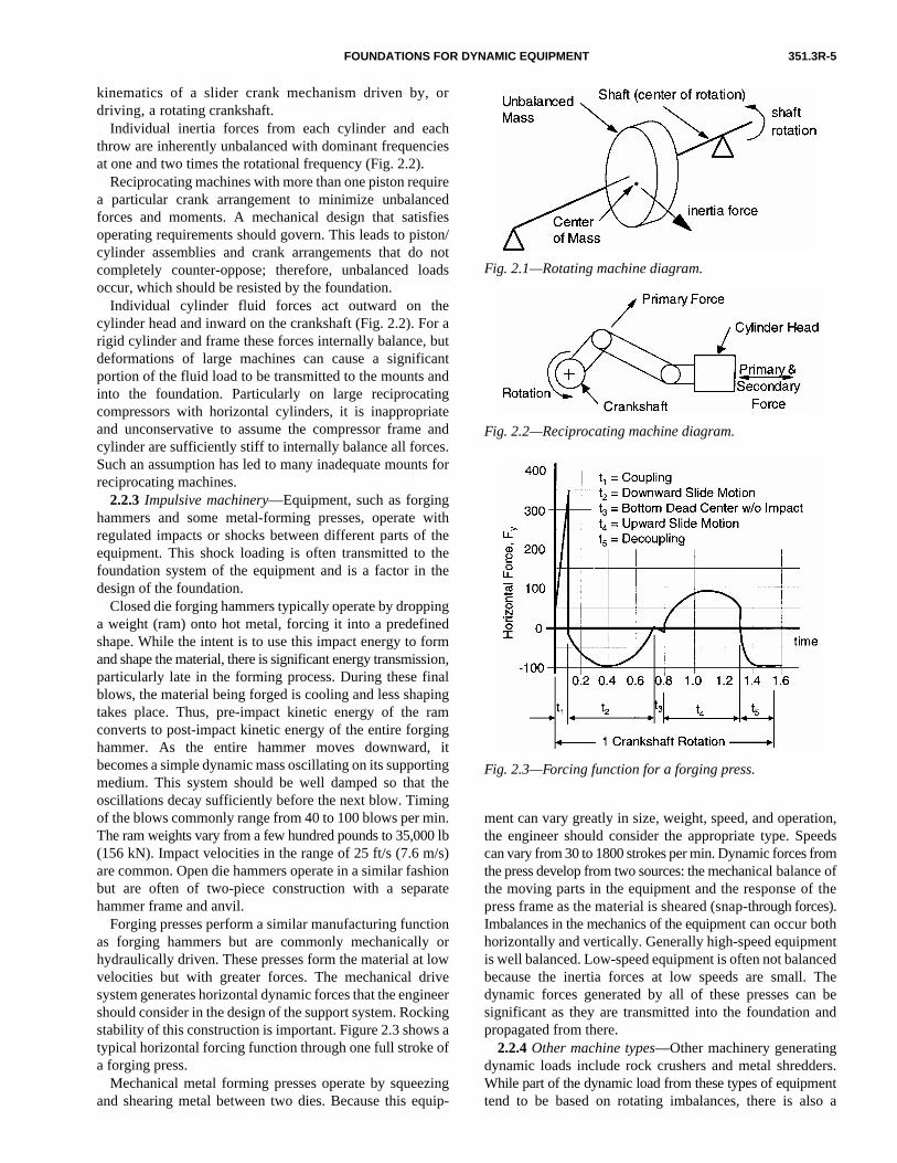
Unbalanced forces in rotating machines are created whenthe mass centroid of the rotating part does not coincide withthe center of rotation (Fig. 2.1). This dynamic force is a functionof the shaft mass, speed of rotation, and the magnitude of theoffset. The offset should be minor under manufacturedconditions when the machine is well balanced, clean, andwithout wear or erosion. Changes in alignment, operationnear resonance, blade loss, and other malfunctions orundesirable conditions can greatly increase the force appliedto its bearings by the rotor. Because rotating machinesnormally trip and shut down at some vibration limit, a real-istic continuous dynamic load on the foundation is thatresulting from vibration just below the trip level.
2.2.2 Reciprocating machinery—For reciprocatingmachinery, such as compressors and diesel engines, a pistonmoving in a cylinder interacts with a fluid through the
FOUNDATIONS FOR DYNAMIC EQUIPMENT 351.3R-5
kinematics of a slider crank mechanism driven by, ordriving, a rotating crankshaft.
Individual inertia forces from each cylinder and eachthrow are inherently unbalanced with dominant frequenciesat one and two times the rotational frequency (Fig. 2.2).
Reciprocating machines with more than one piston requirea particular crank arrangement to minimize unbalancedforces and moments. A mechanical design that satisfiesoperating requirements should govern. This leads to piston/cylinder assemblies and crank arrangements that do notcompletely counter-oppose; therefore, unbalanced loadsoccur, which should be resisted by the foundation.
Individual cylinder fluid forces act outward on thecylinder head and inward on the crankshaft (Fig. 2.2). For arigid cylinder and frame these forces internally balance, butdeformations of large machines can cause a significantportion of the fluid load to be transmitted to the mounts andinto the foundation. Particularly on large reciprocatingcompressors with horizontal cylinders, it is inappropriateand unconservative to assume the compressor frame andcylinder are sufficiently stiff to internally balance all forces.Such an assumption has led to many inadequate mounts forreciprocating machines.
2.2.3 Impulsive machinery—Equipment, such as forginghammers and some metal-forming presses, operate withregulated impacts or shocks between different parts of theequipment. This shock loading is often transmitted to thefoundation system of the equipment and is a factor in thedesign of the foundation.
Closed die forging hammers typically operate by droppinga weight (ram) onto hot metal, forcing it into a predefinedshape. While the intent is to use this impact energy to formand shape the material, there is significant energy transmission,particularly late in the forming process. During these finalblows, the material being forged is cooling and less shapingtakes place. Thus, pre-impact kinetic energy of the ramconverts to post-impact kinetic energy of the entire forginghammer. As the entire hammer moves downward, itbecomes a simple dynamic mass oscillating on its supportingmedium. This system should be well damped so that theoscillations decay sufficiently before the next blow. Timingof the blows commonly range from 40 to 100 blows per min.The ram weights vary from a few hundred pounds to 35,000 lb(156 kN). Impact velocities in the range of 25 ft/s (7.6 m/s)are common. Open die hammers operate in a similar fashionbut are often of two-piece construction with a separatehammer frame and anvil.
Forging presses perform a similar manufacturing functionas forging hammers but are commonly mechanically orhydraulically driven. These presses form the material at lowvelocities but with greater forces. The mechanical drivesystem generates horizontal dynamic forces that the engineershould consider in the design of the support system. Rockingstability of this construction is important. Figure 2.3 shows atypical horizontal forcing function through one full stroke ofa forging press.
Mechanical metal forming presses operate by squeezingand shearing metal between two dies. Because this equip-
ment can vary greatly in size, weight, speed, and operation,the engineer should consider the appropriate type. Speedscan vary from 30 to 1800 strokes per min. Dynamic forces fromthe press develop from two sources: the mechanical balance ofthe moving parts in the equipment and the response of thepress frame as the material is sheared (snap-through forces).Imbalances in the mechanics of the equipment can occur bothhorizontally and vertically. Generally high-speed equipmentis well balanced. Low-speed equipment is often not balancedbecause the inertia forces at low speeds are small. Thedynamic forces generated by all of these presses can besignificant as they are transmitted into the foundation andpropagated from there.
2.2.4 Other machine types—Other machinery generatingdynamic loads include rock crushers and metal shredders.While part of the dynamic load from these types of equipmenttend to be based on rotating imbalances, there is also a
Fig. 2.1—Rotating machine diagram.
Fig. 2.2—Reciprocating machine diagram.
Fig. 2.3—Forcing function for a forging press.
351.3R-6 ACI COMMITTEE REPORT
random character to the dynamic signal that varies with theparticular operation.
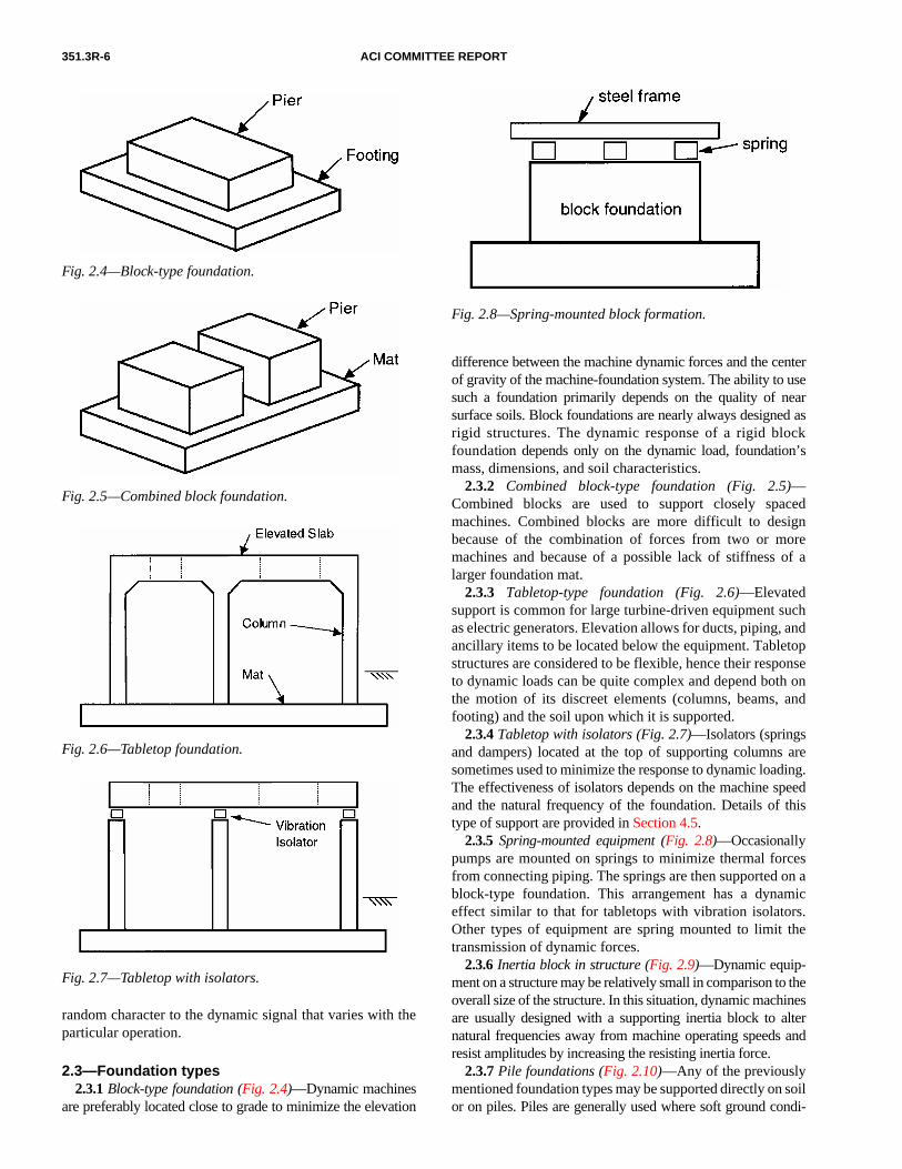
2.3—Foundation types2.3.1 Block-type foundation (Fig. 2.4)—Dynamic machines
are preferably located close to grade to minimize the elevation
Fig. 2.4—Block-type foundation.
Fig. 2.5—Combined block foundation.
Fig. 2.6—Tabletop foundation.
Fig. 2.7—Tabletop with isolators.
difference between the machine dynamic forces and the centerof gravity of the machine-foundation system. The ability to usesuch a foundation primarily depends on the quality of nearsurface soils. Block foundations are nearly always designed asrigid structures. The dynamic response of a rigid blockfoundation depends only on the dynamic load, foundation’smass, dimensions, and soil characteristics.
2.3.2 Combined block-type foundation (Fig. 2.5)—Combined blocks are used to support closely spacedmachines. Combined blocks are more difficult to designbecause of the combination of forces from two or moremachines and because of a possible lack of stiffness of alarger foundation mat.
2.3.3 Tabletop-type foundation (Fig. 2.6)—Elevatedsupport is common for large turbine-driven equipment suchas electric generators. Elevation allows for ducts, piping, andancillary items to be located below the equipment. Tabletopstructures are considered to be flexible, hence their responseto dynamic loads can be quite complex and depend both onthe motion of its discreet elements (columns, beams, andfooting) and the soil upon which it is supported.
2.3.4 Tabletop with isolators (Fig. 2.7)—Isolators (springsand dampers) located at the top of supporting columns aresometimes used to minimize the response to dynamic loading.The effectiveness of isolators depends on the machine speedand the natural frequency of the foundation. Details of thistype of support are provided in Section 4.5.
2.3.5 Spring-mounted equipment (Fig. 2.8)—Occasionallypumps are mounted on springs to minimize thermal forcesfrom connecting piping. The springs are then supported on ablock-type foundation. This arrangement has a dynamiceffect similar to that for tabletops with vibration isolators.Other types of equipment are spring mounted to limit thetransmission of dynamic forces.
2.3.6 Inertia block in structure (Fig. 2.9)—Dynamic equip-ment on a structure may be relatively small in comparison to theoverall size of the structure. In this situation, dynamic machinesare usually designed with a supporting inertia block to alternatural frequencies away from machine operating speeds andresist amplitudes by increasing the resisting inertia force.
2.3.7 Pile foundations (Fig. 2.10)—Any of the previouslymentioned foundation types may be supported directly on soilor on piles. Piles are generally used where soft ground condi-
Fig. 2.8—Spring-mounted block formation.

FOUNDATIONS FOR DYNAMIC EQUIPMENT 351.3R-7
tions result in low allowable contact pressures and excessivesettlement for a mat-type foundation. Piles use end bearing,frictional side adhesion, or a combination of both to transferaxial loads into the underlying soil. Transverse loads areresisted by soil pressure bearing against the side of the pilecap or against the side of the piles. Various types of piles areused including drilled piers, auger cast piles, and driven piles.
CHAPTER 3—DESIGN CRITERIA3.1—Overview of design criteria
The main issues in the design of concrete foundations thatsupport machinery are defining the anticipated loads, estab-lishing the performance criteria, and providing for thesethrough proper proportioning and detailing of structuralmembers. Yet, behind this straightforward definition lies theneed for careful attention to the interfaces between machine,mounting system, and concrete foundation.
The loads on machine foundations may be both static anddynamic. Static loads are principally a function of theweights of the machine and all its auxiliary equipment.Dynamic loads, which occur during the operation of themachine, result from forces generated by unbalance, inertiaof moving parts, or both, and by the flow of fluid and gasesfor some machines. The magnitude of these dynamic loadsprimarily depends upon the machine’s operating speed andthe type, size, weight, and arrangement (position) of movingparts within the casing.
The basic goal in the design of a machine foundation is tolimit its motion to amplitudes that neither endanger the satis-factory operation of the machine nor disturb people working inthe immediate vicinity (Gazetas 1983). Allowable amplitudesdepend on the speed, location, and criticality or function of
Fig. 2.9—Inertia block in structure.
Fig. 2.10—Pile-supported foundation.
the machine. Other limiting dynamic criteria affecting thedesign may include avoiding resonance and excessive trans-missibility to the supporting soil or structure. Thus, a keyingredient to a successful design is the careful engineeringanalysis of the soil-foundation response to dynamic loadsfrom the machine operation.
The foundation’s response to dynamic loads can be signif-icantly influenced by the soil on which it is constructed.Consequently, critical soil parameters, such as the dynamicsoil shear modulus, are preferably determined from a fieldinvestigation and laboratory tests rather than relying ongeneralized correlations based on broad soil classifications.Due to the inherent variability of soil, the dynamic responseof machine foundations is often evaluated using a range ofvalues for the critical soil properties.
Furthermore, a machinery support structure or foundation isdesigned with adequate structural strength to resist the worstpossible combination of loads occurring over its service life.This often includes limiting soil-bearing pressures to wellwithin allowable limits to ensure a more predictable dynamicresponse and prevent excessive settlements and soil failures.Additionally, concrete members are designed and detailed toprevent cracking due to fatigue and stress reversals caused bydynamic loads, and the machine’s mounting system is designedand detailed to transmit loads from the machine into thefoundation, according to the criteria in Section 3.6.
3.2—Foundation and equipment loadsFoundations supporting reciprocating or rotating compressors,
turbines, generators and motors, presses, and other machineryshould withstand all the forces that may be imposed on themduring their service life. Machine foundations are uniquebecause they may be subjected to significant dynamic loadsduring operation in addition to normal design loads ofgravity, wind, and earthquake. The magnitude and charac-teristics of the operating loads depend on the type, size,speed, and layout of the machine.
Generally, the weight of the machine, center of gravity,surface areas, and operating speeds are readily availablefrom the manufacturer of the machine. Establishing appro-priate values for dynamic loads is best accomplished throughcareful communication and clear understanding between themachine manufacturer and foundation design engineer as tothe purpose, and planned use for the requested information,and the definition of the information provided. It is in the bestinterests of all parties (machine manufacturer, foundationdesign engineer, installer, and operator) to ensure effectivedefinition and communication of data and its appropriate use.Machines always experience some level of unbalance, vibra-tion, and force transmitted through the bearings. Under someoff-design conditions, such as wear, the forces may increasesignificantly. The machine manufacturer and foundationdesign engineer should work together so that their combinedknowledge achieves an integrated system structure whichrobustly serves the needs of its owner and operator and with-stands all expected loads.
Sections 3.2.1 to 3.2.6 provide commonly used methodsfor determining machine-induced forces and other design
351.3R-8 ACI COMMITTEE REPORT
loads for foundations supporting machinery. They includedefinitions and other information on dynamic loads to berequested from the machine manufacturer and alternativeassumptions to apply when such data are unavailable or areunder-predicted.
3.2.1 Static loads3.2.1.1 Dead loads—A major function of the foundation
is to support gravity (dead) loads due to the weight of themachine, auxiliary equipment, pipe, valves, and deadweightof the foundation structure. The weights of the machine compo-nents are normally supplied by the machine manufacturer. Thedistribution of the weight of the machine on the foundationdepends on the location of support points (chocks, soleplates)and on the flexibility of the machine frame. Typically, thereare multiple support points, and, thus, the distribution isstatically indeterminate. In many cases, the machine manufac-turer provides a loading diagram showing the vertical loads ateach support point. When this information is not available, it iscommon to assume the machine frame is rigid and that itsweight is appropriately distributed between support points.
3.2.1.2 Live loads—Live loads are produced by personnel,tools, and maintenance equipment and materials. The live loadsused in design should be the maximum loads expected duringthe service life of the machine. For most designs, live loads areuniformly distributed over the floor areas of platforms ofelevated support structures or to the access areas around at-grade foundations. Typical live loads vary from 60 lbf/ft2
(2.9 kPa) for personnel to as much as 150 lbf/ft2 (7.2 kPa) formaintenance equipment and materials.
3.2.1.3 Wind loads—Loads due to wind on the surfaceareas of the machine, auxiliary equipment, and the supportfoundation are based on the design wind speed for the partic-ular site and are normally calculated in accordance with thegoverning local code or standard. Wind loads rarely governthe design of machine foundations except, perhaps, when themachine is located in an enclosure that is also supported bythe foundation.
When designing machine foundations and support structures,most practitioners use the wind load provisions of ASCE 7. Theanalytical procedure of ASCE 7 provides wind pressures andforces for use in the design of the main wind-force resistingsystems and anchorage of machine components.
Most structural systems involving machines and machinefoundations are relatively stiff (natural frequency in thelateral direction greater than 1 Hz). Consequently, thesystems can be treated as rigid with respect to the wind gusteffect factor, and simplified procedures can be used. If themachine is supported on flexible isolators and is exposed tothe wind, the rigid assumption may not be reasonable, andmore elaborate treatment of the gust effects is necessary asdescribed in ASCE 7 for flexible structural systems.
Appropriate consideration of the exposure conditions andimportance factors is also required to be consistent with thefacilities requirements.
3.2.1.4 Seismic loads—Machinery foundations locatedin seismically active regions are analyzed for seismic loads.Before 2000, these loads were determined in accordancewith methods prescribed in one of various regional building
codes (such as the UBC, the SBC, or the NBC) and standardssuch as ASCE 7 and SEAOC Blue Book.
The publication of the IBC 2000 provides building officialswith the opportunity to replace the former regional codeswith a code that has nationwide applicability. The seismicrequirements in IBC 2000 and ASCE 7-98 are essentiallyidentical, as both are based on the 1997 NEHRP (FEMA 302)provisions.
The IBC and its reference documents contain provisionsfor design of nonstructural components, including dynamicmachinery, for seismic loads. For machinery supportedabove grade or on more flexible elevated pedestals, seismicamplification factors are also specified.
3.2.1.5 Static operating loads—Static operating loadsinclude the weight of gas or liquid in the machinery equipmentduring normal operation and forces, such as the drive torquedeveloped by some machines at the connection between thedrive mechanism and driven machinery. Static operatingloads can also include forces caused by thermal growth ofthe machinery equipment and connecting piping. Time-varying (dynamic) loads generated by machines duringoperation are covered elsewhere in this report.
Machines such as compressors and generators requiresome form of drive mechanism, either integral with themachine or separate from it. When the drive mechanism isnonintegral, such as a separate electric motor, reciprocatingengine, and gas or steam turbine, it produces a net externaldrive torque on the driven machine. The torque is equal inmagnitude and opposite in direction on the driver and drivenmachine. The normal torque (sometimes called drive torque)is generally applied to the foundation as a static force couplein the vertical direction acting about the centerline of theshaft of the machine. The magnitude of the normal torque isoften computed from the following formula
NT = lbf-ft (3-1)
NT = N-m
whereNT = normal torque, ft-lbf (m-N);Ps = power being transmitted by the shaft at the
connection, horsepower (kilowatts); andfo = operating speed, rpm.
The torque load is generally resolved into a vertical forcecouple by dividing it by the center-to-center distance betweenlongitudinal soleplates or anchor points (Fig. 3.1(a)). When themachine is supported by transverse soleplates only, thetorque is applied along the width of the soleplate assuming astraight line variation of force (Fig. 3.1(b)). Normal torquecan also be caused by jet forces on turbine blades. In this caseit is applied to the foundation in the opposite direction fromthe rotation of the rotor.
The torque on a generator stator is applied in the samedirection as the rotation of the rotor and can be high due to
5250( ) Ps( )fo
---------------------------
9550( ) Ps( )fo
---------------------------

FOUNDATIONS FOR DYNAMIC EQUIPMENT 351.3R-9
startup or an electrical short circuit. Startup torque, a propertyof electric motors, should be obtained from the motormanufacturer. The torque created by an electrical shortcircuit is considered a malfunction, emergency, or accidentalload and is generally reported separately by the machinerymanufacturer. Often in the design for this phenomenon, themagnitude of the emergency drive torque is determined byapplying a magnification factor to the normal torque.Consultation with the generator manufacturer is necessary toestablish the appropriate magnification factor.
3.2.1.6 Special loads for elevated-type foundations—Toensure adequate strength and deflection control, thefollowing special static loading conditions are recommendedin some proprietary standards for large equipment onelevated-type foundations:
1. Vertical force equal to 50% of the total weight of eachmachine;
2. Horizontal force (in the transverse direction) equal to25% of the total weight of each machine; and
3. Horizontal force (in the longitudinal direction) equal to25% of the total weight of each machine.
These forces are additive to normal gravity loads and areconsidered to act at the centerline of the machine shaft.Loads 1, 2, and 3 are not considered to act concurrently withone another.
3.2.1.7 Erection and maintenance loads—Erection andmaintenance loads are temporary loads from equipment,such as cranes and forklifts, required for installing ordismantling machine components during erection or mainte-nance. Erection loads are usually furnished in the manufac-turer’s foundation load drawing and should be used inconjunction with other specified dead, live, and environmentalloads. Maintenance loads occur any time the equipment isbeing drained, cleaned, repaired, and realigned or when thecomponents are being removed or replaced. Loads mayresult from maintenance equipment, davits, and hoists. Envi-ronmental loads, such as full wind and earthquake, are notusually assumed to act with maintenance loads, which gener-ally occur for only a relatively short duration.
3.2.1.8 Thermal loads—Changing temperatures ofmachines and their foundations cause expansions andcontractions, and distortions, causing the various parts to tryto slide on the support surfaces. The magnitude of theresulting frictional forces depends on the magnitude of thetemperature change, the location of the supports, and on thecondition of the support surfaces. The thermal forces do notimpose a net force on the foundation to be resisted by soil orpiles because the forces on any surface are balanced by equaland opposite forces on other support surfaces. Thermalforces, however, may govern the design of the grout system,pedestals, and hold downs.
Calculation of the exact thermal loading is very difficultbecause it depends on a number of factors, includingdistance between anchor points, magnitude of temperaturechange, the material and condition of the sliding surface, andthe magnitude of the vertical load on each soleplate. Lackinga rigorous analysis, the magnitude of the frictional load maybe calculated as follows
Force = (friction coefficient)(load acting through soleplate) (3-2)
The friction coefficient generally varies from 0.2 to 0.5.Loads acting through the soleplate include: machine deadload, normal torque load, anchor bolt load, and piping loads.
Heat transfer to the foundation can be by convection across anair gap (for example, gap between sump and block) and byconduction through points of physical contact. The resultanttemperature gradients induce deformations, strains, and stresses.
When evaluating thermal stress, the calculations arestrongly influenced by the stiffness and restraint againstdeformation for the structural member in question. There-fore, it is important to consider the self-relieving nature ofthermal stress due to deformation to prevent being overlyconservative in the analysis. As the thermal forces areapplied to the foundation member by the machine, the foun-dation member changes length and thereby provides reducedresistance to the machine forces. This phenomenon can havethe effect of reducing the thermal forces from the machine.
Accurate determinations of concrete surface temperaturesand thermal gradients are also important. Under steady-statenormal operating conditions, temperature distributionsacross structural sections are usually linear. The air gapbetween the machine casing and foundation provides asignificant means for dissipating heat, and its effect shouldbe included when establishing surface temperatures.
Normally, the expected thermal deflection at variousbearings is estimated by the manufacturer, based on pastfield measurements on existing units. The machine erectorthen compensates for the thermal deflection during installation.
Fig. 3.1—Equivalent forces for torque loads.

351.3R-10 ACI COMMITTEE REPORT
Reports are available (Mandke and Smalley 1992;Mandke and Smalley 1989; and Smalley 1985) that illustratethe effects of thermal loads and deflections in the concretefoundation of a large reciprocating compressor and theirinfluence on the machine.
3.2.2 Rotating machine loads—Typical heavy rotatingmachinery include centrifugal air and gas compressors, hori-zontal and vertical fluid pumps, generators, rotating steam andgas turbine drivers, centrifuges, electric motor drivers, fans,and blowers. These types of machinery are characterized bythe rotating motion of one or more impellers or rotors.
3.2.2.1 Dynamic loads due to unbalanced masses—Unbalanced forces in rotating machines are created when themass centroid of the rotating part does not coincide with theaxis of rotation. In theory, it is possible to precisely balancethe rotating elements of rotating machinery. In practice, thisis never achieved; slight mass eccentricities always remain.During operation, the eccentric rotating mass producescentrifugal forces that are proportional to the square ofmachine speed. Centrifugal forces generally increase duringthe service life of the machine due to conditions such asmachine wear, rotor play, and dirt accumulation.
A rotating machine transmits dynamic force to the foundationpredominantly through its bearings (with small, generallyunimportant exceptions such as seals and the air gap in amotor). The forces acting at the bearings are a function of thelevel and axial distribution of unbalance, the geometry of therotor and its bearings, the speed of rotation, and the detaileddynamic characteristics of the rotor-bearing system. At or neara critical speed, the force from rotating unbalance can besubstantially amplified, sometimes by a factor of five or more.
Ideally, the determination of the transmitted force underdifferent conditions of unbalance and at different speedsresults from a dynamic analysis of the rotor-bearing system,using an appropriate combination of computer programs forcalculating bearing dynamic characteristics and the responseto unbalance of a flexible rotor in its bearings. Such an analysiswould usually be performed by the machine manufacturer.Results of such analyses, especially values for transmittedbearing forces, represent the best source of information foruse by the foundation design engineer. This and otherapproaches used in practice to quantify the magnitude ofdynamic force transmitted to the foundation are discussed inSections 3.2.2.1a to 3.2.2.1.3e.
3.2.2.1a Dynamic load provided by the manufac-turer—The engineer should request and the machine manu-facturer should provide the following information:
Design levels of unbalance and basis—This informationdocuments the unbalance level the subsequent transmittedforces are based on.
Dynamic forces transmitted to the bearing pedestalsunder the following conditions—
a) Under design unbalance levels over operating speedrange;
b) At highest vibration when negotiating critical speeds;c) At a vibration level where the machine is just short of
tripping on high vibration; and
d) Under the maximum level of upset condition themachine is designed to survive (for example, loss of one ormore blades).
Items a and b document the predicted dynamic forcesresulting from levels of unbalance assumed in design fornormal operation. Using these forces, it is possible to predictthe normal dynamic vibration of the machine on its foundation.
Item c identifies a maximum level of transmitted forcewith which the machine could operate continuously withouttripping; the foundation should have the strength to toleratesuch a dynamic force on a continuous basis.
Item d identifies the higher level of dynamic force, whichcould occur under occasional upset conditions over a shortperiod of time. If the machine is designed to tolerate thislevel of dynamic force for a short period of time, then thefoundation should also be able to tolerate it for a similarperiod of time.
If an independent dynamic analysis of the rotor-bearingsystem is performed by the end user or by a third party, suchan analysis can provide some or all of the above dynamicforces transmitted to the foundation.
By assuming that the dynamic force transmitted to thebearings equals the rotating unbalanced force generated bythe rotor, information on unbalance can provide an estimateof the transmitted force.
3.2.2.1b Machine unbalance provided by the manufac-turer—When the mass unbalance (eccentricity) is known orstated by the manufacturer, the resulting dynamic forceamplitude is
Fo = mr emωo2Sf /12 lbf (3-3)
Fo = mr emωo2Sf /1000 N
whereFo = dynamic force amplitude (zero-to-peak), lbf (N);mr = rotating mass, lbm (kg);em = mass eccentricity, in. (mm);ωo = circular operating frequency of the machine (rad/s);
andSf = service factor, used to account for increased
unbalance during the service life of the machine,generally greater than or equal to 2.
3.2.2.1c Machine unbalance meeting industrycriteria—Many rotating machines are balanced to an initialbalance quality either in accordance with the manufacturer’sprocedures or as specified by the purchaser. ISO 1940 andASA/ANSI S2.19 define balance quality in terms of a constantemωo. For example, the normal balance quality Q for parts ofprocess-plant machinery is 0.25 in./s (6.3 mm/s). Other typicalbalance quality grade examples are shown in Table 3.1. Tomeet these criteria a rotor intended for faster speeds should bebetter balanced than one operating at a slower speed. Usingthis approach, Eq. (3-3) can be rewritten as
Fo = mrQωoSf /12 lbf (3-4)
Fo = mrQωoSf /1000 N

FOUNDATIONS FOR DYNAMIC EQUIPMENT 351.3R-11
API 617 and API 684 work with maximum residual unbal-ance Umax criteria for petroleum processing applications. Themass eccentricity is determined by dividing Umax by the rotorweight. For axial and centrifugal compressors with maximumcontinuous operating speeds greater than 25,000 rpm, API 617establishes a maximum allowable mass eccentricity of 10 ×10–6 in. (250 nm). For compressors operating at slower speeds,the maximum allowable mass eccentricity is
em = 0.25/fo in. (3-5)
em = 6.35/fo mm
where fo = operating speed, rpm ≤ 25,000 rpm.
This permitted initial mass eccentricity is tighter than ISObalance quality grade G2.5, which would be applied to thistype of equipment (Table 3.1, turbo-compressors) under ISO1940. As such, the dynamic force computed from this APIconsideration will be quite small and a larger service factormight be used to have a realistic design force.
API 617 also identifies a limitation on the peak-to-peakvibration amplitude during mechanical testing of thecompressor with the equipment operating at its maximumcontinuous speed ((12,000/fo)0.5 in. [25.4(12,000/fo)0.5 mm]).Some design firms use this criterion and a service factor Sfof 2.0 to compute the dynamic force amplitude as
Table 3.1—Balance quality grades for selected groups of representative rigid rotors (excerpted from ANSI/ASA S2.19)Balance quality guide
Product of eω, in./s (mm/s) Rotor types—general examples
G1600 63 (1600) Crankshaft/drives of rigidly mounted, large,two-cycle engines
G630 2.5 (630) Crankshaft/drives of rigidly mounted, large,four-cycle engines
G250 10 (250) Crankshaft/drives of rigidly mounted, fast,four-cylinder diesel engines
G100 4 (100) Crankshaft/drives of fast diesel engines with six or more cylinders
G40 1.6 (40)Crankshaft/drives of elastically mounted, fast four-cycle engines (gasoline or diesel) with six or more cylinders
G16 0.6 (16)
Parts of crushing machines; drive shafts (propeller shafts, cardan shafts) with special requirements; crankshaft/drives of engines with six or more cylinders under special requirements
G6.3 0.25 (6.3)
Parts of process plant machines; centrifuge drums, paper machinery rolls, print rolls; fans; flywheels; pump impellers; machine tool and general machinery parts; medium and large electricarmatures (of electric motors having at least80 mm shaft height) without special requirement
G2.5 0.1 (2.5)
Gas and steam turbines, including marine main turbines; rigid turbo-generator rotors; turbo-compressors; machine tool drives; medium and large electric armatures with special requirements;turbine driven pumps
G1 0.04 (1) Grinding machine drives
G0.4 0.015 (0.4) Spindles, discs, and armatures of precisiongrinders
(3-6)
where Wr = rotating weight, lbf (N).
3.2.2.1d Dynamic load determined from an empiricalformula—Rotating machine manufacturers often do notreport the unbalance that remains after balancing. Conse-quently, empirical formulas are frequently used to ensurethat foundations are designed for some minimum unbalance,which generally includes some allowance for increasingunbalance over time. One general purpose empirical methodassumes that balancing improves with machine speed andthat there is a linear relationship between the unbalancedforces and the machine speed. The zero-to-peak centrifugalforce amplitude from one such commonly used expression is
(3-7)
Equations (3-3), (3-4), (3-6), and (3-7) appear to be verydifferent: the exponents on the speed of rotation vary from 1to 1.5 to 2, constants vary widely, and different variablesappear. Some equations use mass, others use weight. Inreality, the equations are more similar than they appear.Given the right understanding of Q as a replacement for eω,Eq. (3-3), (3-4), and (3-7) take on the same character. Theseequations then indicate that the design force at operatingspeed varies linearly with both the mass of the rotating bodyand the operating rotational speed. Once that state is identified,Eq. (3-3) can be adjusted to reflect the actual speed of rotation,and the dynamic centrifugal force is seen to vary with thesquare of the speed. Restating Eq. (3-6) and (3-7) in the formof Eq. (3-3) allows for the development of an effective eccen-tricity implied within these equations with the comparisonshown in Fig. 3.2. Equation (3-7) produces the same result asEq. (3-4) using Q = 0.25 in./s (6.3 mm/s), and Sf = 2.5.
The centrifugal forces due to mass unbalance are consideredto act at the center of gravity of the rotating part and varyharmonically at the speed of the machine in the two orthogonaldirections perpendicular to the shaft. The forces in the twoorthogonal directions are equal in magnitude and 90 degreesout of phase and are transmitted to the foundation through the
FoWr fo
1.5
322,000-------------------=
FoWr fo
6000------------=
Fig. 3.2—Comparison of effective eccentricity.

351.3R-12 ACI COMMITTEE REPORT
bearings. Schenck (1990) provides useful information aboutbalance quality for various classes of machinery.
3.2.2.1e Machine unbalance determined from tripvibration level and effective bearing stiffness—Because arotor is often set to trip on high vibration, it can be expectedto operate continuously at any vibration level up to the triplimit. Given the effective bearing stiffness, it is possible tocalculate the maximum dynamic force amplitude as
Fo = Vmax Keff (3-8)
whereVmax = the maximum allowable vibration, in. (mm); andKeff = the effective bearing stiffness, lbf/in. (N/mm).
To use this approach, the manufacturer should provideeffective bearing stiffness or the engineer should calculate itfrom the bearing geometry and operating conditions (such asviscosity and speed).
3.2.2.2 Loads from multiple rotating machines—If afoundation supports multiple rotating machines, the engineershould compute unbalanced force based on the mass, unbal-ance, and operating speed of each rotating component. Theresponse to each rotating mass is then combined to determinethe total response. Some practitioners, depending on thespecific situation of machine size and criticality, find itadvantageous to combine the unbalanced forces from eachrotating component into a single resultant unbalanced force.The method of combining two dynamic forces is up to indi-vidual judgment and often involves some approximations. Insome cases, loads or responses can be added absolutely. Inother cases, the loads are treated as out-of-phase so thattwisting effects are increased. Often, the operating speed ofthe equipment should be considered. Even if operatingspeeds are nominally the same, the design engineer shouldrecognize that during normal operation, the speed of themachines will vary and beating effects can develop. Beatingeffects develop as two machines operate at close to the samespeed. At one point in time, responses to the two machines areadditive and motions are maximized. A short time later, theresponses cancel each other and the motions are minimized.The net effect is a continual cyclic rising and falling of motion.
Fig. 3.3—Crack mechanism.
3.2.3 Reciprocating machine loads—Internal-combustionengines, piston-type compressors and pumps, some metalforming presses, steam engines, and other machinery arecharacterized by the rotating motion of a master crankshaftand the linear reciprocating motion of connected pistons orsliders. The motion of these components cause cyclicallyvarying forces, often called reciprocating forces.
3.2.3.1 Primary and secondary reciprocating loads—The simplest type of reciprocating machine uses a singlecrank mechanism as shown in Fig. 3.3. The idealization ofthis mechanism consists of a piston that moves within aguiding cylinder, a crank of length r that rotates about acrank shaft, and a connecting rod of length L. The connectingrod is attached to the piston at point P and to the crank atpoint C. The wrist pin P oscillates while the crank pin Cfollows a circular path. This idealized single cylinder illus-trates the concept of a machine producing both primary andsecondary reciprocating forces.
If the crank is assumed to rotate at a constant angularvelocity ωo, the translational acceleration of the piston alongits axis may be evaluated. If Zp is defined as the pistondisplacement toward the crankshaft (local Z-axis), anexpression can be written for Zp at any time t. Further, thevelocity and acceleration can also be obtained by taking the firstand second derivatives of the displacement expression withrespect to time. The displacement, velocity, and accelerationexpressions for the motion of the piston are as follows
(3-9)
(3-10)
..Zp (3-11)
whereZp = piston displacement, in. (mm);r = length of crank, in. (mm);L = length of connecting rod, in. (mm);ωo = circular operating frequency of the machine (rad/s); andt = time, s.
Note that the expressions contain two terms each with asine or cosine; the term that varies with the frequency of therotation, ωo, is referred to as the primary term while the termthat varies at twice the frequency of rotation, 2ωo, is calledthe secondary term.
Similar expressions can be developed for the local Z-axis(parallel to piston movement) and local Y-axis (perpendic-ular to piston movement) motion of the rotating parts of thecrank. If any unbalance in the crankshaft is replaced by amass concentrated at the crank pin C, such that the inertiaforces are the same as in the original system, the followingterms for motion at point C can be written
Zp r r2
4L------+
r ωot r4L------ 2ωotcos+cos
–=
Z· p rωo ωot r2L------+ 2ωotsinsin
=
rωo2 ωot r
L--- 2ωotcoscos
=

FOUNDATIONS FOR DYNAMIC EQUIPMENT 351.3R-13
yp = –r sinωot (3-12)
= –r ωcosωot (3-13)
= r ωo2sinωot (3-14)
zp = r(1 – cosωot) (3-15)
= rωosinωot (3-16)
= r ωo2cosωot (3-17)
whereyp = crank pin displacement in local Y-axis, in. (mm); andzp = crank pin displacement in local Z-axis, in. (mm).
Identifying a part of the connecting rod (usually 1/3 of itsmass) plus the piston as the reciprocating mass mrec concen-trated at point P and designating the remainder of theconnecting rod plus the crank as the rotating mass mrotconcentrated at point C, expressions for the unbalancedforces are as follows
Parallel to piston movement
(3-18)
Perpendicular to piston movement
(3-19)
Note that Eq. (3.18) consists of two terms, a primary force
(mrec + mrot)rωo2cosωot (3-20)
and a secondary force
(3-21)
whereas Eq. (3-19) has only a primary component.3.2.3.2 Compressor gas loads—A reciprocating
compressor raises the pressure of a certain flow of gas byimparting reciprocating motion on a piston within a cylinder.The piston normally compresses gas during both directionsof reciprocating motion. As gas flows to and from each end,the pressure of the gas increases as it is compressed by eachstroke of the piston. The increase in pressure within thecylinder creates reaction forces on the head and crank endsof the piston which alternate as gas flows to and from eachend of the cylinder.
yp·
yp··
zp·
zp··
Fz mrec mrot+( )rωo2 ωot mrec
r2ωo2
L----------- 2ωotcos+cos=
FY mrotrωo2 ωotsin=
mrecr2ωo
2
L----------- 2ωotcos=
The gas force contributed to the piston rod equals theinstantaneous difference between the pressure force actingon the head and crank end of the piston as shown in Fig. 3.4.
The following formulation can be used to estimate themaximum force acting on the piston rod of an individualdouble-acting cylinder
Frod = [(Phead)(Ahead) – (Pcrank)(Acrank)] F1 (3-22)
Ahead = (π /4)Bc2 (3-23)
Acrank = (π/4)(Bc2 – Drod
2) (3-24)
whereFrod = force acting on piston rod, lbf (N);Ahead,Acrank = head and crank areas, in.2 (mm2);Bc = cylinder bore diameter, in. (mm);Drod = rod diameter, in. (mm);Phead,Pcrank = instantaneous head and crank pressures, psi,
(MPa); andF1 = correction factor.
The head and crank end pressures vary continuously andthe differential force takes both positive and negative netvalues during each cycle of piston motion. The normalapproach is to establish the head and crank pressures usingthe maximum and minimum suction and discharge pressures.For design purposes, it is common to multiply Eq. (3-22) by afactor F1 to help account for the natural tendency of gas forcesto exceed the values based directly on suction and dischargepressures due to flow resistances and pulsations. Machineswith good pulsation control and low external flow resistancemay achieve F1 as small as 1.1; for machines with lowcompression ratio, high pulsations, or highly resistive flowthrough piping and nozzles, F1 can approach 1.5 or evenhigher. A reasonable working value for F1 is 1.15 to 1.2.
Preferably, the maximum rod force resulting from gaspressures is based on knowledge of the continuous variation ofpressure in the cylinder (measured or predicted). In a repairsituation, measured cylinder pressure variation using a cylinderanalyzer provides the most accurate value of gas forces. Evenwithout cylinder pressure analysis, extreme operating values of
Fig. 3.4—Schematic of double-acting compressor cylinderand piston.

351.3R-14 ACI COMMITTEE REPORT
suction and discharge pressure for each stage should berecorded before the repair and used in the Eq. (3-22).
On new compressors, the engineer should ask the machinemanufacturer to provide values for maximum compressiveand tensile gas loads on each cylinder rod and, if these arebased on suction and discharge pressures, to recommend avalue of F1.
Gas forces act on the crankshaft with an equal and oppositereaction on the cylinder. Thus, crankshaft and cylinderforces globally balance each other. Between the crankshaftand the cylinder, however, the compressor frame stretches orcontracts in tension or compression under the action of thegas forces. The forces due to frame deflections are trans-mitted to the foundation through connections with thecompressor frame. When acting without slippage, the frameand foundation become an integral structure and togetherstretch or contract under the gas loads.
The magnitude of gas force transferred into the foundationdepends on the relative flexibility of the compressor frame.A very stiff frame transmits only a small fraction of the gasforce while a very flexible frame transmits most or all of theforce. Similar comments apply to the transfer of individualcylinder inertia forces.
Based on limited comparisons using finite element analysis(Smalley 1988), the following guideline is suggested for gasand inertia force loads transmitted to the foundation by atypical compressor
Fblock = Frod/Fred (3-25)
(Fbolt)CHG = [(Frod)/(Nbolt)CHG]/Fred (3-26)
(Fbolt)frame = [(Funbalance/(Nbolt)]/Fred (3-27)
whereFblock = the force acting outward on the block from
which concrete stresses should be calcu-lated, lbf (N);
(Fbolt)CHG = the force to be restrained by friction at thecross head guide tie-down bolts, lbf (N);
(Fbolt)frame = the force to be restrained by friction at theframe tie-down bolts, lbf (N);
Fred = a force reduction factor with suggestedvalue of 2, to account for the fraction ofindividual cylinder load carried by thecompressor frame (“frame rigidity factor”);
(Nbolt)CHG = the number of bolts holding down onecrosshead guide;
(Nbolt)frame = the number of bolts holding down theframe, per cylinder;
Frod = force acting on piston rod, from Eq. (3-22),lbf (N); and
Funbalance = the maximum value from Eq. (3-18) appliedusing parameters for a horizontalcompressor cylinder, lbf (N).
The factor Fred is used to simplify a complex problem, thusavoiding the application of unrealistically high loads on the
anchor bolts and the foundation block. The mechanicsinvolved in transmitting loads are complex and cannot easilybe reduced to a simple relationship between a few parametersbeyond the given load equations. A detailed finite-elementanalysis of metal compressor frame, chock mounts, concreteblock, and grout will account for the relative flexibility of theframe and its foundation in determining individual anchorbolt loads and implicitly provide a value for Fred. If theframe is very stiff relative to the foundation, the value forFred will be higher, implying more of the transmitted loadsare carried by the frame and less by the anchor bolts andfoundation block. Based on experience, a value of 2 for thisfactor is conservatively low; however, higher values havebeen seen with frames designed to be especially stiff.
Simplifying this approach, one report (Smalley andHarrell 1997) suggests using a finite element analysis tocalculate forces transmitted to the anchor bolts. If a finiteelement analysis is not possible, the engineer should getfrom the machine manufacturer or calculate the maximumhorizontal gas force and maximum horizontal inertia forcefor any throw or cylinder. The mounts, anchor bolts, andblocks are then designed for
FTHROW = (greater of FGMAX or FIMAX)/2 (3-28)
whereFGMAX = maximum horizontal gas force on a throw or
cylinder, lbf (N);FIMAX = maximum horizontal inertia force on a throw or
cylinder, lbf (N); andFTHROW = horizontal force to be resisted by each throw’s
anchor bolts, lbf (N).3.2.3.3 Reciprocating inertia loads for multicylinder
machines—As a practical matter, most reciprocatingmachines have more than one cylinder, and manufacturersarrange the machine components in a manner that minimizesthe net unbalanced forces. For example, rotating parts likethe crankshaft can be balanced by adding or removingcorrecting weights. Translating parts like pistons and thosethat exhibit both rotation and translation, like connectingrods, can be arranged in such a way as to minimize the unbal-anced forces and moments generated. Seldom, if ever, is itpossible to perfectly balance reciprocating machines.
The forces generated by reciprocating mechanisms arefunctions of the mass, stroke, piston arrangement,connecting rod size, crank throw orientation (phase angle),and the mass and arrangement of counterweights on thecrankshaft. For this reason, calculating the reciprocatingforces for multicylinder machines can be quite complex andare therefore normally provided by the machine manufac-turer. If the machine is an integral engine compressor, it caninclude, in one frame, cylinders oriented horizontally, verti-cally, or in between, all with reciprocating inertias.
Some machine manufacturers place displacement transducersand accelerometers on strategic points on the machinery. Theycan then measure displacements and accelerations at thosepoints for several operational frequencies to determine the

FOUNDATIONS FOR DYNAMIC EQUIPMENT 351.3R-15
magnitude of the unbalanced forces and couples for multi-cylinder machines.
3.2.3.4 Estimating reciprocating inertia forces frommulticylinder machines—In cases where the manufacturer’sdata are unavailable or components are being replaced, theengineer should use hand calculations to estimate the recip-rocating forces from a multicylinder machine. One suchprocedure for a machine having n number of cylinders isdiscussed by Mandke and Troxler (1992). Section 3.7summarizes this method.
3.2.4 Impulsive machine loads—The impulsive loadgenerated by a forging hammer is caused by the impact of thehammer ram onto the hammer anvil. This impact processtransfers the kinetic energy of the ram into kinetic energy ofthe entire hammer assembly. The post-impact velocity of thehammer is represented by
(3-29)
wherevh = post-impact hammer velocity, ft/s (m/s);Mr = ram mass including dies and ancillary parts, lbm (kg);Mh = hammer mass including any auxiliary foundation, lbm
(kg);αh = ram rebound velocity relative to impact velocity; andvr = ram impact velocity, ft/s (m/s).
General experience indicates that αh is approximately60% for many forging hammer installations. From that point,the hammer foundation performance can be assessed as arigid body oscillating as a single degree-of-freedom systemwith an initial velocity of vh.
For metal-forming presses, the dynamic forces developfrom two sources: the mechanical movement of the presscomponents and material-forming process. Each of theseforces is unique to the press design and application and needsto be evaluated with proper information from the pressmanufacturer and the owner.
The press mechanics often include rotating and recipro-cating components. The dynamic forces from these indi-vidual pieces follow the rules established in earlier sectionsof this document for rotating and reciprocating components.Only the press manufacturer familiar with all the internalcomponents can knowledgeably calculate the specificforces. Figure 2.3 presents a horizontal force time-history fora forging press. Similar presses can be expected to havesimilar characteristics; however, the particular values andtiming data differ.
The press drive mechanisms include geared and direct-drive systems. Depending on the design, these drives may ormay not be balanced. The press slide travels verticallythrough a set stroke of 1/2 in. (12 mm) to several inches at agiven speed. Some small presses may have inclinable bedsso that the slide is not moving vertically. It is often adequateto assume that the slide moves in a vertical path defined by acircularly rotating crankshaft, that is
vhMr
Mh
------- 1 αh+( )vr=
(3-30)
whereds = displacement of the slide, in. (mm);S = press stroke, in. (mm); andωo = circular operating frequency of the machine (rad/s).
This leads to a dynamic inertia force from the slide of
lbf (3-31)
N
whereFs = dynamic inertia force of slide, lbf (N); andmd = slide mass including the effects of any balance mech-
anism, lbm (kg).This assumption is based on simple circular motions and
simple linkages. Other systems may be in-place to increasethe press force and improve the timing. These other systemsmay increase the acceleration of the unbalanced weights andthus alter the magnitude and frequency components of thedynamic force transmitted to the foundation.
3.2.5 Loading conditions—During their lives, machineryequipment support structures and foundations undergodifferent loading conditions including erection, testing, shut-down, maintenance, and normal and abnormal operation. Foreach loading condition, there can be one or more combinationsof loads that apply to the structure or foundation. The followingloading conditions are generally considered in design:• Erection condition represents the design loads that act
on the structure/foundation during its construction;• Testing condition represents the design loads that act on
the structure/foundation while the equipment beingsupported is undergoing testing, such as hydrotest;
• Empty (shutdown) represents the design loads that acton the structure when the supported equipment is at itsleast weight due to removal of process fluids, applicableinternals, or both as a result of maintenance or otherout-of-service disruption;
• Normal operating condition represents the design loadingduring periods of normal equipment operation; and
• Abnormal operating condition represents the designloading during periods when unusual or extreme operatingloads act on the structure/foundation.
3.2.6 Load combinations—Table 3.2 shows the generalclassification of loads for use in determining the applicableload factors in strength design (ACI 318). In considering soilstresses, the normal approach is working stress designwithout load factors and with overall factors of safety iden-tified as appropriate by geotechnical engineers. The loadcombinations frequently used for the various load conditionsare as follows:
1. Erectiona) Dead load + erection forces
ds t( ) S2--- ωot( )sin=
Fs t( ) mdωo2S2--- ωot( ) 12⁄sin=
Fs t( ) mdωo2S2--- ωot( ) 1000⁄sin=

351.3R-16 ACI COMMITTEE REPORT
b) Dead load + erection forces + reduced wind + snow,ice, or rain
c) Dead load + erection forces + seismic + snow, ice, or rain2. Testing
a) Dead load + test loadsb) Dead load + test loads + live + snow, ice, or rainc) Dead load + test loads + reduced wind + snow, ice,
or rain3. Empty (shutdown)
a) Dead load + maintenance forces + live load + snow,ice, or rain
4. Normal operationa) Dead loadb) Dead load + thermal load + machine forces + live
loads + wind + snow, ice, or rainc) Dead load + thermal load + machine forces + seismic
+ snow, ice, or rain5) Abnormal operation
a) Dead load + upset (abnormal) machine loads + live +reduced wind
It is common to only use some fraction of full wind, such as80% in combination with erection loads and 33% for testloads, due to the short duration of these conditions (ASCE 7).
3.3—Dynamic soil propertiesSoil dynamics deals with engineering properties and
behavior of soil under dynamic stress. For the dynamic analysisof machine foundations, soil properties, such as Poisson’sratio, dynamic shear modulus, and damping of soil, aregenerally required.
Though this work is typically completed by a geotechnicalengineer, this section provides a general overview ofmethods used to determine the various soil properties. Manyreferences are available that provide a greater level of detailon both theory and standard practice, including Das (1993),Bowles (1996), Fang (1991), and Arya, O’Neill, and Pincus(1979). Seed and Idriss (1970) provide greater detail onitems that influence different soil properties.
This section does not cover considerations that affect thesuitability of a given soil to support a dynamic machinefoundation. Problems could include excessive settlementcaused by dynamic or static loads, liquefaction, dimensional
Table 3.2—Load classifications for ultimate strength design
Design loadsLoad
classification
Weight of structure, equipment, internals, insulation, and platformsTemporary loads and forces caused by erectionFluid loads during testing and operationThermal loadsAnchor and guide loads
Dead
Platform and walkway loadsMaterials to be temporarily stored during maintenanceMaterials normally stored during operation such as toolsand maintenance equipmentVibrating equipment forcesImpact loads for hoist and equipment handling utilities
Live
Earthquake loadsTransportation loadsSnow, ice, or rain loadsWind loads
Environmental
stability of a cohesive soil, frost heave, or any other relevantsoils concern.
In general, problems involving the dynamic properties ofsoils are divided into small and large strain amplituderesponses. For machine foundations, the amplitudes ofdynamic motion, and consequently the strains in the soil, areusually low (strains less than10–3%). A foundation that issubjected to an earthquake or blast loading is likely toundergo large deformations and, therefore, induce largestrains in the soil. The information in this report is onlyapplicable for typical machine foundation strains. Refer toSeed and Idriss (1970) for information on strain-relatedeffects on shear modulus and material damping.
The key soil properties, Poisson’s ratio and dynamic shearmodulus, may be significantly affected by water table vari-ations. Prudence suggests that in determining these properties,such variations be considered and assessed, usually inconjunction with the geotechnical engineers. This approachoften results in expanding the range of properties to beconsidered in the design phase.
3.3.1 Poisson’s ratio—Poisson’s ratio ν, which is the ratioof the strain in the direction perpendicular to loading to thestrain in the direction of loading, is used to calculate both thesoil stiffness and damping. Poisson’s ratio can be computedfrom the measured values of wave velocities traveling throughthe soil. These computations, however, are difficult. Thestiffness and damping of a foundation system are generallyinsensitive to variations of Poisson’s ratio common in soils.
Generally, Poisson’s ratio varies from 0.25 to 0.35 forcohesionless soils and from 0.35 to 0.45 for cohesive soils. Ifno specific values of Poisson’s ratio are available, then, fordesign purposes, the engineer may take Poisson’s ratio as0.33 for cohesionless soils and 0.40 for cohesive soils.
3.3.2 Dynamic shear modulus—Dynamic shear modulusG is the most important soil parameter influencing thedynamic behavior of the soil-foundation system. Togetherwith Poisson’s ratio, it is used to calculate soil impedance.Refer to Section 4.2 for the discussion on soil impedance.
The dynamic shear modulus represents the slope of theshear stress versus shear strain curve. Most soils do notrespond elastically to shear strains; they respond with acombination of elastic and plastic strain. For that reason,plotting shear stress versus shear strain results in a curve nota straight line. The value of G varies based on the strainconsidered. The lower the strain, the higher the dynamicshear modulus.
Several methods are available for obtaining useful valuesof dynamic shear modulus:• Field measurements of stress wave velocities of in-place
soils;• Laboratory tests on soil samples; and• Correlation to other soil properties.
Due to variations inherent in the determination of dynamicshear modulus values, it may be appropriate to complete morethan one foundation analysis. One analysis could becompleted with the minimum possible value, one could becompleted using the maximum possible value, and then addi-tional analyses could be completed with intermediate values.
FOUNDATIONS FOR DYNAMIC EQUIPMENT 351.3R-17
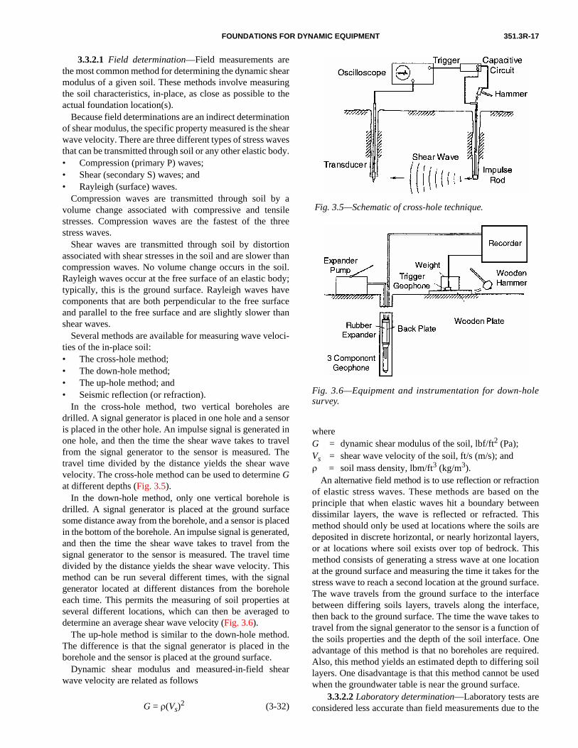
3.3.2.1 Field determination—Field measurements arethe most common method for determining the dynamic shearmodulus of a given soil. These methods involve measuringthe soil characteristics, in-place, as close as possible to theactual foundation location(s).
Because field determinations are an indirect determinationof shear modulus, the specific property measured is the shearwave velocity. There are three different types of stress wavesthat can be transmitted through soil or any other elastic body.• Compression (primary P) waves;• Shear (secondary S) waves; and• Rayleigh (surface) waves.
Compression waves are transmitted through soil by avolume change associated with compressive and tensilestresses. Compression waves are the fastest of the threestress waves.
Shear waves are transmitted through soil by distortionassociated with shear stresses in the soil and are slower thancompression waves. No volume change occurs in the soil.Rayleigh waves occur at the free surface of an elastic body;typically, this is the ground surface. Rayleigh waves havecomponents that are both perpendicular to the free surfaceand parallel to the free surface and are slightly slower thanshear waves.
Several methods are available for measuring wave veloci-ties of the in-place soil: • The cross-hole method;• The down-hole method;• The up-hole method; and• Seismic reflection (or refraction).
In the cross-hole method, two vertical boreholes aredrilled. A signal generator is placed in one hole and a sensoris placed in the other hole. An impulse signal is generated inone hole, and then the time the shear wave takes to travelfrom the signal generator to the sensor is measured. Thetravel time divided by the distance yields the shear wavevelocity. The cross-hole method can be used to determine Gat different depths (Fig. 3.5).
In the down-hole method, only one vertical borehole isdrilled. A signal generator is placed at the ground surfacesome distance away from the borehole, and a sensor is placedin the bottom of the borehole. An impulse signal is generated,and then the time the shear wave takes to travel from thesignal generator to the sensor is measured. The travel timedivided by the distance yields the shear wave velocity. Thismethod can be run several different times, with the signalgenerator located at different distances from the boreholeeach time. This permits the measuring of soil properties atseveral different locations, which can then be averaged todetermine an average shear wave velocity (Fig. 3.6).
The up-hole method is similar to the down-hole method.The difference is that the signal generator is placed in theborehole and the sensor is placed at the ground surface.
Dynamic shear modulus and measured-in-field shearwave velocity are related as follows
G = ρ(Vs)2 (3-32)
whereG = dynamic shear modulus of the soil, lbf/ft2 (Pa);Vs = shear wave velocity of the soil, ft/s (m/s); andρ = soil mass density, lbm/ft3 (kg/m3).
An alternative field method is to use reflection or refractionof elastic stress waves. These methods are based on theprinciple that when elastic waves hit a boundary betweendissimilar layers, the wave is reflected or refracted. Thismethod should only be used at locations where the soils aredeposited in discrete horizontal, or nearly horizontal layers,or at locations where soil exists over top of bedrock. Thismethod consists of generating a stress wave at one locationat the ground surface and measuring the time it takes for thestress wave to reach a second location at the ground surface.The wave travels from the ground surface to the interfacebetween differing soils layers, travels along the interface,then back to the ground surface. The time the wave takes totravel from the signal generator to the sensor is a function ofthe soils properties and the depth of the soil interface. Oneadvantage of this method is that no boreholes are required.Also, this method yields an estimated depth to differing soillayers. One disadvantage is that this method cannot be usedwhen the groundwater table is near the ground surface.
3.3.2.2 Laboratory determination—Laboratory tests areconsidered less accurate than field measurements due to the
Fig. 3.5—Schematic of cross-hole technique.
Fig. 3.6—Equipment and instrumentation for down-holesurvey.
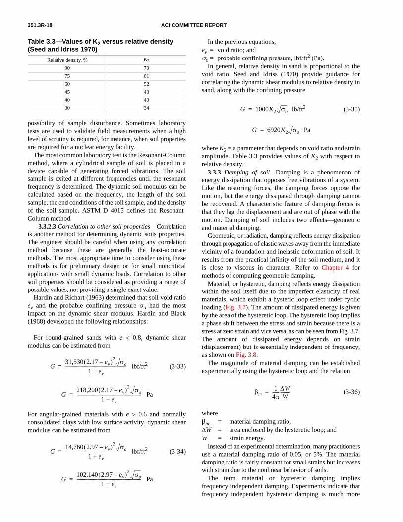
351.3R-18 ACI COMMITTEE REPORT
possibility of sample disturbance. Sometimes laboratorytests are used to validate field measurements when a highlevel of scrutiny is required, for instance, when soil propertiesare required for a nuclear energy facility.
The most common laboratory test is the Resonant-Columnmethod, where a cylindrical sample of soil is placed in adevice capable of generating forced vibrations. The soilsample is exited at different frequencies until the resonantfrequency is determined. The dynamic soil modulus can becalculated based on the frequency, the length of the soilsample, the end conditions of the soil sample, and the densityof the soil sample. ASTM D 4015 defines the Resonant-Column method.
3.3.2.3 Correlation to other soil properties—Correlationis another method for determining dynamic soils properties.The engineer should be careful when using any correlationmethod because these are generally the least-accuratemethods. The most appropriate time to consider using thesemethods is for preliminary design or for small noncriticalapplications with small dynamic loads. Correlation to othersoil properties should be considered as providing a range ofpossible values, not providing a single exact value.
Hardin and Richart (1963) determined that soil void ratioev and the probable confining pressure σo had the mostimpact on the dynamic shear modulus. Hardin and Black(1968) developed the following relationships:
For round-grained sands with e < 0.8, dynamic shearmodulus can be estimated from
lbf/ft2 (3-33)
Pa
For angular-grained materials with e > 0.6 and normallyconsolidated clays with low surface activity, dynamic shearmodulus can be estimated from
lbf/ft2 (3-34)
Pa
G31,530 2.17 ev–( )2 σo
1 ev+-------------------------------------------------------=
G218,200 2.17 ev–( )2 σo
1 ev+----------------------------------------------------------=
G14,760 2.97 ev–( )2 σo
1 ev+-------------------------------------------------------=
G102,140 2.97 ev–( )2 σo
1 ev+----------------------------------------------------------=
Table 3.3—Values of K2 versus relative density (Seed and Idriss 1970)
Relative density, % K2
90 70
75 61
60 52
45 43
40 40
30 34
In the previous equations,ev = void ratio; andσo = probable confining pressure, lbf/ft2 (Pa).
In general, relative density in sand is proportional to thevoid ratio. Seed and Idriss (1970) provide guidance forcorrelating the dynamic shear modulus to relative density insand, along with the confining pressure
lb/ft2 (3-35)
Pa
where K2 = a parameter that depends on void ratio and strainamplitude. Table 3.3 provides values of K2 with respect torelative density.
3.3.3 Damping of soil—Damping is a phenomenon ofenergy dissipation that opposes free vibrations of a system.Like the restoring forces, the damping forces oppose themotion, but the energy dissipated through damping cannotbe recovered. A characteristic feature of damping forces isthat they lag the displacement and are out of phase with themotion. Damping of soil includes two effects—geometricand material damping.
Geometric, or radiation, damping reflects energy dissipationthrough propagation of elastic waves away from the immediatevicinity of a foundation and inelastic deformation of soil. Itresults from the practical infinity of the soil medium, and itis close to viscous in character. Refer to Chapter 4 formethods of computing geometric damping.
Material, or hysteretic, damping reflects energy dissipationwithin the soil itself due to the imperfect elasticity of realmaterials, which exhibit a hysteric loop effect under cyclicloading (Fig. 3.7). The amount of dissipated energy is givenby the area of the hysteretic loop. The hysteretic loop impliesa phase shift between the stress and strain because there is astress at zero strain and vice versa, as can be seen from Fig. 3.7.The amount of dissipated energy depends on strain(displacement) but is essentially independent of frequency,as shown on Fig. 3.8.
The magnitude of material damping can be establishedexperimentally using the hysteretic loop and the relation
(3-36)
whereβm = material damping ratio;∆W = area enclosed by the hysteretic loop; andW = strain energy.
Instead of an experimental determination, many practitionersuse a material damping ratio of 0.05, or 5%. The materialdamping ratio is fairly constant for small strains but increaseswith strain due to the nonlinear behavior of soils.
The term material or hysteretic damping impliesfrequency independent damping. Experiments indicate thatfrequency independent hysteretic damping is much more
G 1000K2 σo=
G 6920K2 σo=
βm1
4π------ ∆W
W---------=

FOUNDATIONS FOR DYNAMIC EQUIPMENT 351.3R-19
typical of soils than viscous damping because the area of thehysteretic loop does not grow in proportion to the frequency.
3.4—Vibration performance criteriaThe main purposes of the foundation system with respect
to dynamic loads include limiting vibrations, internal loads,and stresses within the equipment. The foundation systemalso limits vibrations in the areas around the equipmentwhere other vibration-sensitive equipment may be installed,personnel may have to work on a regular basis, or damage tothe surrounding structures may occur. These performancecriteria are usually established based on vibration amplitudesat key points on or around the equipment and foundationsystem. These amplitudes may be based on displacement,velocity, or acceleration units. Displacement limitations arecommonly based on peak-to-peak amplitudes measured inmils (0.001 in.) or microns (10–6 m). Velocity limitations aretypically based on either peak velocities or root-mean-square(rms) velocities in units of inch per second or millimeter persecond. Displacement criteria are almost always frequencydependent with greater motions tolerated at slower speeds.Velocity criteria may depend on frequency but are oftenindependent. Acceleration criteria may be constant withfrequency or dependent.
Some types of equipment operate at a constant speed whileother types operate across a range of speeds. The foundationengineer should consider the effect of these speed variationsduring the foundation design.
3.4.1 Machine limits—The vibration limits applicable tothe machine are normally set by the equipment manufactureror are specified by the equipment operator or owner. Thelimits are usually predicated on either limiting damage to theequipment or ensuring proper performance of the equipment.Limits specified by operators of the machinery and designengineers are usually based on such factors as experience orthe installation of additional vibration monitoring equipment.
For rotating equipment (fans, pumps, and turbines), thenormal criterion limits vibration displacements or velocities atthe bearings of the rotating shaft. Excessive vibrations of thebearings increase maintenance requirements and lead topremature failure of the bearings. Often, rotating equipmenthas vibration switches to stop the equipment if vibrationsbecome excessive.
Reciprocating equipment (diesel generators, compressors,and similar machinery) tends to be more dynamically ruggedthan rotating equipment. At the same time, it often generatesgreater dynamic forces. While the limits may be higher,motions are measured at bearing locations. In addition, opera-tors of reciprocating compressors often monitor vibrations ofthe compressor base relative to the foundation (sometimescalled “frame movement”) as a measure of the foundation andmachine-mounting condition and integrity.
Impulsive machines (presses, forging hammers) tend not tohave specific vibration limitations as controllable by the foun-dation design. With these machines, it is important to recognizethe difference between the inertial forces and equipmentdynamics as contrasted with the foundation system dynamics.The forces with the equipment can generate significant
accelerations and stresses that are unrelated to the stiffness,mass, or other design aspect of the foundation system. Thus,monitoring accelerations in particular on an equipment framemay not be indicative of foundation suitability or adequacy.
Researchers have presented various studies and papersaddressing the issues of machinery vibration limits. Thisvariety is reflected in the standards of engineering companies,plant owners, and industry standards. When the equipmentmanufacturer does not establish limits, recommendation fromISO 10816-1, Blake (1964), and Baxter and Bernhard (1967)are often followed. Most of these studies relate directly torotating equipment. In many cases they are also applicable toreciprocating equipment. Rarely do these studies apply toimpulsive equipment.
ISO publishes ISO 10816 in a series of six parts to addressevaluation of machinery vibration by measurements on thenonrotating parts. Part 1 provides general guidelines and setsthe overall rules with the subsequent parts providing specificvalues for specific machinery types. These standards areprimarily directed toward in-place measurements for theassessment of machinery operation. They are not intended toidentify design standards. Design engineers, however, haveused predecessor documents to ISO 10816 as a baseline fordesign calculations and can be expected to do similarly withthese more recent standards.
The document presents vibration criteria in terms of rmsvelocity. Where there is complexity in the vibration signal(beyond simple rotor unbalance), the rms velocity basisprovides the broad measure of vibration severity and can becorrelated to likely machine damage. For situations wherethe pattern of motion is fairly characterized by one simpleharmonic, such as simple rotor unbalance, the rms velocitiescan be multiplied by √2 to determine corresponding peakvelocity criteria. For these same cases, displacements can becalculated as
Fig. 3.7—Hysteretic loop.
Fig. 3.8—Comparison of viscous and hysteretic damping.

351.3R-20 ACI COMMITTEE REPORT
(3-37)
wherev = displacement amplitude, in. (cm);v′ = velocity, in./s (cm/s);ωm = circular frequency of motion, rad/s; andfm = frequency of motion, Hz.
The rms velocity yields an rms displacement, and a peakvelocity results in a zero-to-peak displacement value, whichcan be doubled to determine a peak-to-peak displacement
v v′ωm
------- v′2πfm
-----------= =
Table 3.4—Service factors from Blake (Richart, Hall, and Woods 1970)
ItemBolted down
Not bolted down
Single-stage centrifugal pump, electric motor, fan 1.0 0.4
Typical chemical processing equipment, noncritical 1.0 0.4
Turbine, turbo-generator, centrifugal compressor 1.6 0.6
Centrifugal, stiff-shaft (at basket housing), multi-stage centrifugal pump 2.0 0.8
Miscellaneous equipment, characteristics unknown 2.0 0.8
Centrifuge, shaft-suspended, on shaft near basket 0.5 0.2
Centrifuge, link-suspended, slung 0.3 0.1
Notes: 1. Vibration is measured at the bearing housing except as noted; 2. Machine tools are excluded; and 3) Compared or measured displacements are multiplied by the appropriate service factor before comparing with Fig. 3.9.
Fig. 3.9—Vibration criteria for rotating machinery (Blake1964, as modified by Arya, O’Neill, and Pincus 1979).
value. If the motion is not a simple pure harmonic motion, asimple relationship among the rms displacement, rms velocity,peak velocity, zero-to-peak displacement, and peak-to-peakdisplacement does not exist.
ISO 10816-1 identifies four areas of interest with respectto the magnitude of vibration measured:• Zone A: vibration typical of new equipment;• Zone B: vibration normally considered acceptable for
long-term operation;• Zone C: vibration normally considered unsatisfactory
for long-term operation; and• Zone D: vibration normally considered severe enough
to damage the machine.The subsequent parts of ISO 10816 establish the boundaries
between these zones as applicable to specific equipment.Part 2, ISO 10816-2, establishes criteria for large, land-based, steam-turbine generator sets rated over 67,000 horse-power (50 MW). The most general of the standards is Part 3,ISO 10816-3, which addresses in-place evaluation of generalindustrial machinery nominally more than 15 kW and operatingbetween 120 and 15,000 rpm. Within ISO 10816-3, criteria areestablished for four different groups of machinery, andprovisions include either flexible or rigid support conditions.Criteria are also established based on both rms velocity and rmsdisplacement. Part 4, ISO 10816-4, identifies evaluation criteriafor gas-turbine-driven power generation units (excludingaircraft derivatives) operating between 3000 and 20,000 rpm.Part 5 (ISO 10816-5) applies to machine sets in hydro-powerfacilities and pumping plants. Part 6, ISO 10816-6, providesevaluation criteria for reciprocating machines with powerratings over 134 horsepower (100 kW). The scope of Part 5 isnot applicable to general equipment foundations and thecriteria of Part 6 are not sufficiently substantiated and definedto be currently useful.
Another document available for establishing vibrationlimitation is from Lifshits (Lifshits, Simmons, and Smalley1986). This document follows Blake’s approach of identi-fying five different categories from No Faults to Danger ofImmediate Failure. In addition, a series of correction factorsare established to broaden the applicability to a wider rangeof equipment and measurement data.
Blake’s paper (Blake 1964) has become a common basisfor some industries and firms. His work presented a standardvibration chart for process equipment with performancerated from “No Faults (typical of new equipment)” to“Dangerous (shut it down now to avoid danger).” The chartwas primarily intended to aid plant personnel in assessing fieldinstallations and determining maintenance plans. Servicefactors for different types of equipment are used to allowwidespread use of the basic chart. This tool uses vibrationdisplacement (in. or mm) rather than velocity and covers speedranges from 100 to 10,000 rpm. Figure 3.9 and Table 3.4present the basic chart and service factors established by Blake.
Baxter and Bernhard (1967) offered more general vibrationtolerances in a paper that has also become widely referenced.Again with primary interest to the plant maintenance operations,they established the General Machinery Vibration SeverityChart, shown in Fig. 3.10, with severity ranging from extremely

FOUNDATIONS FOR DYNAMIC EQUIPMENT 351.3R-21
smooth to very rough. These are plotted as displacement versusvibration frequency so that the various categories are differenti-ated along lines of constant peak velocity.
The American Petroleum Institute (API) also has a seriesof standards for equipment common in the petrochemicalindustry (541, 610, 612, 613, 617, 618, and 619). ISO 10816-3can be applied for some large electrical motors; however,most design offices do not generally perform rigorous analysesfor these items.
Figure 3.11 provides a comparison of five generic standardsagainst four corporate standards. To the extent possible, thecomparisons are presented on a common basis. In particular,the comparison is based on equipment that is in service,perhaps with minor faults, but which could continue inservice indefinitely. The Blake line is at the upper limit of thezone identifying operation with minor faults with a servicefactor of one applicable for fans, some pumps, and similarequipment. The Lifshits line separates the acceptable andmarginal zones and includes a K of 0.7, reflecting equipmentwith rigid rotors. The ISO lines are drawn at the upper levelof Zone B, normally considered acceptable for long-termoperation. The ISO 10816-3 line is for large machinesbetween 400 and 67,000 horsepower (300 kW and 50 MW)on rigid support systems. The ISO 10816-2 is for largeturbines over 67,000 horsepower (50 MW).
The company standards are used for comparison to calculatemotions at the design stage. For these calculations, the compa-nies prescribe rotor unbalance conditions worse than thoseexpected during delivery and installation. These load defini-tions are consistent with those presented in Section 3.2.2.1.Thus, there is a level of commonality. Company G’s criteriaare for large turbine applications and, thus, most comparableto the ISO 10816-2 criteria. The other company standards arefor general rotating equipment. Company F permits highermotions for reciprocating equipment. In all cases the designcompanies standards reflect that the manufacturer mayestablish equipment-specific criteria that could be morelimiting than their internal criteria.
Figure 3.11 shows that the corporate standards are generallybelow the generic standards because the generic standards areintended for in-place service checks and maintenance decisionsrather than offering initial design criteria. One company isclearly more lenient for very low-speed equipment, but thecorporate standards tend to be similar.
The Shock and Vibration Handbook (Harris 1996)contains further general information on such standards.
3.4.2 Physiological limits—Human perception and sensi-tivity to vibration is ambiguous and subjective. Researchershave studied and investigated this topic, but there are no clearuniform U.S. standards. In Germany, VDI 2057 providesguidance for the engineer. Important issues are the personnelexpectations and needs and the surrounding environment.
ISO 2631 provides guidance for human exposure towhole-body vibration and considers different comfort levelsand duration of exposure. This document does not addressthe extensive complexities identified in ISO 2631. Figure 3.12presents the basic suggested acceleration limits from ISO2631 applicable to longitudinal vibrations (vertical for a
standing person). This figure reflects the time of exposure andfrequency consideration for fatigue-decreased proficiency.The figure shows that people exhibit fatigue and reduced profi-ciency when subjected to small accelerations for long periods orgreater accelerations for shorter periods. The frequency of theaccelerations also impact fatigue and proficiency.
The modified Reiher-Meister figure (barely perceptible,noticeable, and troublesome) is also used to establish limitswith respect to personnel sensitivity, shown in Fig. 3.13.
Fig. 3.10—General Machinery Vibration Severity Chart(Baxter and Bernhard 1967).
Fig. 3.11—Comparison of permissible displacements.

351.3R-22 ACI COMMITTEE REPORT
DIN 4150 is another standard used internationally. Part 3defines permissible velocities suitable for assessment of short-term vibrations on structures, which are given in Table 3.5.Furthermore, Part 2 of this German standard defines limitationsfor allowable vibrations based on perception as a function oflocation (residential, light industrial) and either daytime ornighttime. Most engineering offices do not consider humanperception to vibrations, unless there are extenuating circum-stances (proximity to office or residential areas).
There are no conclusive limitations on the effects of vibrationof surrounding buildings. The Reiher-Meister figure identifies
Fig. 3.12—Longitudinal acceleration limits (adapted fromISO 2631-1).
Fig. 3.13—Reiher-Meister Chart (Richart, Hall, andWoods 1970).
levels of vibration from mining operations that havedamaged structures.
3.4.3 Frequency ratios—The frequency ratio is a term thatrelates the operating speed of the equipment to the naturalfrequencies of the foundation. Engineers or manufacturersrequire that the frequency of the foundation differ from theoperating speed of the equipment by certain margins. Thislimitation is applied to prevent resonance conditions fromdeveloping within the dynamic soil-foundation-equipment.The formulation or presentation of frequency ratios may bebased around either fo/fn or fn/fo (operating frequency tonatural frequency or its inverse), and engineers or manufac-turers should exercise caution to prevent misunderstandings.
A common practice among engineering firms is tocompute the natural frequencies of the basic equipment-foundation and compare the values with the dynamic excitationfrequency. Many companies require that the naturalfrequency be 20 to 33% removed from the operating speed.Some firms have used factors as low as 10% or as high as50%. If the frequencies are well separated, no further evaluationis needed. If there is a potential for resonance, the engineershould either adjust to the foundation size or perform morerefined calculations. Refined calculations may include ananalysis with a deliberately reduced level of damping. Thesize and type of equipment play an important role in thisdecision process.
Frequency ratio is a reasonable design criterion, but onesingle limiting value does not fit all situations. Where thereis greater uncertainty in other design parameters (soil stiffness,for example), more conservatism in the frequency ratio maybe appropriate. Similarly, vibration problems can exist eventhough resonance is not a problem.
3.4.4 Transmissibility—A common tool for the assessmentof vibrations at the design stage is a transmissibility ratio, asshown in Fig. 3.14, which is based on a single degree-of-freedom (SDOF) system with a constant speed fo excitationforce. This ratio identifies the force transmitted through thespring-damper system with the supporting system ascompared with the dynamic force generated by the equip-ment. This ratio should be as low as possible, that is, onlytransmit 20% of the equipment dynamic force into thesupporting system. Low transmissibility implies low vibra-tions in the surroundings, but this is not an absolute truth.
This transmissibility figure assumes that the damping force isdirectly and linearly proportional to the velocity of the SDOF.Where the system characteristics are such that the dampingforce is frequency dependent, the aforementioned represen-
Table 3.5—Short-term permissible values(DIN 4150-3)
Typeof building
Foundation(1 to 10 Hz)
Foundation(10 to 50 Hz)
Foundation(50 to 100 Hz)
Top complete floor (all
frequencies)
Industrial and commercial
0.8 in./s(20 mm/s)
0.8 to 1.6 in./s(20 to 40 mm/s)
1.6 to 2.0 in.s(40 to 50 mm/s)
1.6 in./s(40 mm/s)
Residential 0.2 in./s(5 mm/s)
0.2 to 0.6 in./s(5 to 15 mm/s)
0.6 to 0.8 in./s(15 to 20 mm/s)
0.6 in./s(15 mm/s)
Special or sensitive
0.1 in./s(3 mm/s)
0.1 to 0.3 in./s(3 to mm/s)
0.3 to 0.4 in./s(8 to 10 mm/s)
0.3 in./s(8 mm/s)

FOUNDATIONS FOR DYNAMIC EQUIPMENT 351.3R-23
tation is not accurate. When the damping resistancedecreases at higher frequencies, the deleterious effect ofdamping on force transmissibility can be mitigated.
For soil or pile-supported systems, the transmissibilityratio may not be meaningful. In SDOF models of thesesystems, the spring and damper are provided by the soil and,while the transmissibility of the design may be low, theenergy worked through these system components is motionin the surroundings that may not be acceptable.
3.5—Concrete performance criteriaThe design of the foundation should withstand all applied
loads, both static and dynamic. The foundation should act inunison with the equipment and supporting soil or structure tomeet the deflection limits specified by the machinery manu-facturer or equipment owner.
The service life of a concrete foundation should meet orexceed the anticipated service life of the equipment installedand resist the cyclic stresses from dynamic loads. Crackingshould be minimized to ensure protection of reinforcing steel.
The structural design of all reinforced concrete foundationsshould be in accordance with ACI 318. The engineer may useallowable stress methods for nonprestressed reinforced concrete.
In foundations thicker than 4 ft (1.2 m), the engineer mayuse the minimum reinforcing steel suggested in ACI 207.2R.
API and the Construction Industry Institute published APIRecommended Practice 686/PIP REIE 686, “RecommendedPractice for Machinery Installation and Installation Design.”Chapter 4 of 686/PIP REIE 686 includes design criteria forsoil-supported reinforced concrete foundations that supportsgeneral and special purpose machinery. The concrete used inthe foundation should tolerate its environment during place-ment, curing, and service. The engineer should considervarious exposures such as freezing and thawing, salts ofchlorides and sulfates, sulfate soils, acids, carbonation,repeated wetting and drying, oils, and high temperatures.
In addition to conventional concrete, there are many tech-nologies available—such as admixtures, additives, specialtycements, and preblended products—to help improve place-ment, durability, and performance properties. These addi-tives include water reducers, set-controlling mixtures,shrinkage-compensating admixtures, polymers, silica fumes,fly ash, and fibers.
Many foundations, whether new or repaired, require a fastturnaround to increase production by reducing downtimewithout compromising durability and required strength.These systems may use a combination of preblended orfield-mixed concrete and polymer concrete or grout toreduce downtime to 12 to 72 h, depending on foundationvolume and start-up strength requirements.
3.6—Performance criteria for machine-mounting systems
The machine-mounting system (broadly categorized aseither an anchorage-type or an isolator-type) attaches thedynamic machine to its foundation. It represents a vitalinterface between the machine and the foundation; however,it can suffer from insufficient attention to critical detail by
the foundation engineer and machinery engineer because itfalls between their areas of responsibility. Anchorage-typemachine-mounting systems integrate the foundation and themachine into a single structure. Isolator-type machine-mounting systems separate the machine and the foundationinto two separate systems that may still dynamically interactwith each other. In the processes of design, installation, andoperation, the critical role of both types needs advocacy andthe assurance that interface issues receive attention. Theresearch and development of information on machine-mounting system technology by the Gas MachineryResearch Council (GMRC) during the 1990s reflects theimportance that this group attaches to the anchorage-typemachine-mounting system. This research produced a seriesof reports on machine-mounting topics (Pantermuehl andSmalley 1997a,b; Smalley and Pantermuehl 1997; Smalley1997). These reports, readily retrievable from www.gmrc.org,are essential for those responsible for dynamic machines andtheir foundations.
Most large machines, in spite of careful design for integrityand function by their manufacturers, can internally absorb nomore than a fraction of the forces or thermal growth inherentin their function.
Those responsible for the machine-foundation interfaceshould provide an attachment that transmits the remainingforces for dynamic integrity of the structure yet accommo-dates anticipated differential thermal expansion betweenmachine and foundation. They should recognize the inherentconflicts in these requirements, the physical processes thatcan inhibit performance of these functions, and the lifetimeconstraints (such as limited maintenance and contaminatingmaterials) from which any dynamic machine can suffer as itcontributes to profitable, productive plant operation.
A dynamic machine may tend to get hotter and grow morethan its foundation (in the horizontal plane). The growth canreach several tenths of an inch (0.1 in. = 2.54 mm); combustionturbine casings grow so much that they have to include deliber-ately installed flexibility between hotter and cooler elementsof their own metallic structure. Most machines—such ascompressors, steam turbines, motors, and generators—donot internally relieve their own thermal growth, so themounting system should allow for thermal growth. Thermalgrowth can exert millions of pounds of force (1,000,000 lbf= 4500 kN), a level that cannot be effectively restrained.
Fig. 3.14—Force transmissibility.

351.3R-24 ACI COMMITTEE REPORT
Heat is transferred between the machine and foundationthrough convection, radiation, and conduction. Whileconvection and radiation dominate in the regions where anair gap separates the machine base from the foundation, themounting system provides the primary path for conduction.
Ten critical performance criteria can be identified asgenerally applicable to isolator and anchorage-typemounting systems:
1. A machine-mounting system should tolerate expecteddifferential thermal growth across the interface. This canoccur by combining strength to resist expansion forces andstresses, flexibility to accommodate the deflections, andtolerance for relative sliding across the interface (as themachine grows relative to the foundation);
2. A machine-mounting system should either absorb ortransmit, across the mounting interface, those internallygenerated dynamic forces, resulting from the machine’soperation not absorbed within the machine structure itself.These forces include both vertical and horizontal compo-nents. Flexible mounts that deflect rather than restrain theforces become an option only in cases where the machineand any rigidly attached structure have the structural rigidityneeded to avoid damaging internal stresses and deflections.Large machinery may not meet this criterion;
3. A nominally rigid mount should transmit dynamicforces with only microlevel elastic deformation and negligibledynamic slippage across the interface. The dynamic forcesshould include local forces, such as forces from each individualcylinder, which large machines transmit to the foundationbecause of their flexibility. For reciprocating compressors,this criterion helps ensure that the foundation and machineform an integrated structure;
4. A machine-mounting system should perform its functionfor a long life—typically 25 years or more. Specificationsfrom the operator should include required life;
5. Any maintenance and inspection required to sustainintegrity of the machine-mounting system should have afrequency acceptable to the operator of the machine, forexample, once per year. Engineers, installers, and operators ofthe machine and its foundation should agree to this mainte-nance requirement because the design integrity relies on theexecution of these maintenance functions with this frequency;
6. The bolts that tie the machine to the mounting system,and which form an integral part of the mounting system,should have sufficient stretch and create enough normalforce across all interfaces to meet the force transmission anddeflection performance stated above;
7. The anchor bolt material strength should tolerate theresultant bolt tensile stresses. The mounts, soleplates, andgrout layers compressed by the anchor bolt should toleratethe compressive stresses imposed on them;
8. Any polymeric material (grout or chocks) compressedby the anchor bolts should exhibit a tolerably low amount ofcreep to maintain bolt stretch over the time period betweenmaintenance actions performed to inspect and tighten anchorbolts. Indeed, the machine mount should perform its func-tion, accounting for expected creep, even if maintenanceoccurs less frequently;
9. The mounting system should provide a stable platformfrom which to align the machine. Any deflections of themounting system that occur should remain sufficientlyuniform at different points to preserve acceptable alignmentof the machine. The specifications and use of adjustablechock mounts has become increasingly widespread tocompensate for loss of alignment resulting from creep andother permanent deformations; and
10. The mounting system should impose tolerable loads,stresses, and deformations on the foundation itself. Appro-priate foundation design to make the loads, stresses, anddeformations tolerable remains an essential part of thisperformance criterion. Some of the loads and stresses toconsider include:• Tensile stresses in the concrete at the anchor bolt termi-
nation point, which may cause cracks;• Shear stresses in concrete above anchor bolt termination
points, which, if high enough, might result in pullout;• Interface shear stresses between a grout layer and the
concrete resulting from the typically higher expansionof polymer grout than concrete (best accommodatedwith expansion joints); and
• Hogging or sagging deformation of the concrete blockproduced by heat conduction through the mountingsystem. Air gaps and low conductivity epoxy chockshelp minimize such deformation.
Potential conflicts requiring attention and management inthese performance criteria include:• Requirements to accommodate thermal expansion
while transmitting dynamic forces; and• Requirements to provide a large anchor bolt clamping
force (so that slippage is controlled during transfer ofhigh lateral loads) while stresses and deflections in bolt,foundation, chocks, and grout remain acceptably low.
Physical processes that can influence the ability of themount to meet its performance criteria include:• Creep—Creep of all polymeric materials under compres-
sive load. (Creep means time-dependent deflectionunder load. Deflection increases with time—sometimesdoubling or tripling the initial deflection);
• Differential thermal expansion—This can occur whentwo adjacent components at similar temperatures havedifferent coefficients of thermal expansion, when twoadjacent components of similar coefficients have differenttemperatures or a combination of both. Machinemounts with epoxy materials can experience both typesof differential thermal expansion;
• Friction—Friction is limited by a friction coefficient.Friction defines the maximum force parallel to aninterface that the interface can resist before sliding for agiven normal force between the two interfacing materials;
• Limits on friction—The presence of oil in the interface(typically cutting the dry friction coefficient in half)causes further limits on friction;
• Yield strength—Yield strength of anchor bolts limits thetension available from an anchor bolt and encouragesthe use of high-strength anchor bolts for all criticalapplications;

FOUNDATIONS FOR DYNAMIC EQUIPMENT 351.3R-25
• Cracks—Concrete can crack under tensile loads, andthese cracks can grow with time; and
• Oil—Oil can pool around many machinery installations.Oil aggravates cracks in concrete, particularly underalternating stresses where it induces a hydraulic action. Inmany cases, oil, its additives, or the ambient materials ittransports react with concrete to reduce its strength, par-ticularly in cracks where stresses tend to be high.
Those responsible for machine mounts, as part of a founda-tion, should consider the aforementioned performance criteria,the conflicts that complicate the process of meeting thosecriteria, and the physical processes that inhibit the ability of anyinstallation to meet the performance criteria. Other sections ofthis document address the calculation of loads, stresses, deflec-tions, and the specific limits of strength implicit in differentmaterials. The GMRC reports referred to address all theseissues as they pertain to reciprocating compressors.
3.7—Method for estimating inertia forcesfrom multicylinder machines
The local horizontal Fzi and vertical Fyi unbalanced forcesfor the i-th cylinder located in the horizontal plane can bewritten as
Fzi = (mrec,i + mrot,i)riω2o cos(ωot + αi) (3-38)
+ mrot,i cos2(ωot + αi)
and
(3-39)
wheremrec,i = reciprocating mass for the i-th cylinder;mrot,i = rotating mass of the i-th cylinder;ri = radius of the crank mechanism of the i-th cylinder;Li = length of the connecting rod of the crank mecha-
nism at the i-th cylinder;ωo = circular operating frequency of the machine (rad/s);t = time, s; andαi = the phase angle for the crank radius of the i-th
cylinder, rad.The primary and secondary force components are as
follows(primary)
Fzi′ = (mrec,i + mrot,i)ri cos(ωot + αi) (3-40)
Fyi′ = mrec,iri sin(ωot + αi) (3-41)
(secondary)
ri2ωo
2
Li
-----------
Fyi mrec i, riωo2 ωot αi+( )sin=
ωo2
ωo2
Fzi′′ = (mrot,i)ri cos2(ωot + αi) (3-42)
If the i-th cylinder is oriented at angle θi to a global horizontalz-axis, then the primary and secondary force components,with respect to the global axis, can be rewritten as follows
(primary)
(3-43)
(3-44)
(secondary)
(3-45)
(3-46)
The resultant forces due to n cylinders in global coordinatescan be calculated as follows
(3-47)
(3-48)
(3-49)
(3-50)
The resultant moments due to n cylinders in global coordi-nates can be determined as follows
(moment about y [vertical] axis) (3-51)
(3-52)
(moment about z [horizontal] axis) (3-53)
ri2ωo
2
Li
-----------
FziGP F′zi θicos F′yi θisin= =
FyiGP F′zi θisin F′yi θicos= =
FziGS F′′zi θicos=
FyiGS
F′′zi θisin=
FzGP
FziGP
i 1=
n
∑=
FzGS Fzi
GS
i 1=
n
∑=
FyGP Fyi
GP
i 1=
n
∑=
FyGS Fyi
GS
i 1=
n
∑=
MyGP Fzi
GPXi( )i 1=
n
∑=
MyGS Fzi
GSXi( )i 1=
n
∑=
MzGP Fyi
GPXi( )i 1=
n
∑=

351.3R-26 ACI COMMITTEE REPORT
(3-54)
where Xi = distance along the crankshaft from the referenceorigin to the i-th cylinder.
Equation (3-43) to (3-54) provide instantaneous values oftime-varying inertia (shaking) forces and four time varyingshaking moments for an n cylinder reciprocating machine.To visualize the time variation of these forces and momentsover a revolution of the crankshaft, they can be computed ata series of crank angle values and plotted against crankangle. To obtain maximum values of the primary andsecondary forces and moments (and the phase angle at whichthe maxima occur), they are computed at two orthogonalangles and vectorially combined as shown as followsMaximum global horizontal primary force:
(3-55)
at tan–1
Maximum global horizontal secondary force:
(3-56)
at tan–1
Maximum global vertical primary force:
(3-57)
at tan–1
Maximum global vertical secondary force:
(3-58)
at tan–1
Maximum global horizontal primary moment:
(3-59)
at tan–1
Maximum global horizontal secondary moment:
(3-60)
MzGS Fyi
GSXi( )i 1=
n
∑=
FZGP( )max FZ0
GP( )2
FZ90GP( )
2+[ ]
1 2⁄=
FZ90GP FZ0
GP⁄( )
FZGS( )max FZ0
GS( )2
FZ45GS( )
2+[ ]
1 2⁄=
FZ45GS FZ0
GS⁄( )
FYGP( )max FY0
GP( )2
FY90GP( )
2+[ ]
1 2⁄=
FY90GP FY0
GP⁄( )
FYGS( )max FY0
GS( )2
FY45GS( )
2+[ ]
1 2⁄=
FY45GS FY0
GS⁄( )
MZGP( )max MZ0
GP( )2
MZ90GP( )
2+[ ]
1 2⁄=
MZ90GP MZ0
GP⁄( )
MZGS( )max MZ0
GS( )2
MZ45GS( )
2+[ ]
1 2⁄=
at tan–1
Maximum global vertical primary moment:
(3-61)
at tan–1
Maximum global vertical secondary moment:
(3-62)
at tan–1
where subscripts 0, 45, and 90 represent the value of ωot used tocalculate the force values listed in Eq. (3-55) to (3-62).
CHAPTER 4—DESIGN METHODS AND MATERIALS4.1—Overview of design methods
4.1.1 General considerations—The objectives of themachine foundation design are to assess the dynamicresponse of the foundation and verify compliance with therequired vibration and structural performance criteria.Machine foundation design includes the following steps:
1. Develop a preliminary size for the foundation usingrule-of-thumb approaches, past experience, machine manu-facturer recommendations, and other available data;
2. Calculate the vibration parameters, such as naturalfrequency, amplitudes, velocities, and accelerations, for thepreliminarily sized foundation;
3. Verify that these calculated parameters do not exceedrecommended limits or vibration performance criteria;
4. If necessary, incorporate appropriate modifications inthe foundation design to reduce vibration responses to meetthe specified vibration performance criteria and cost; and
5. Check the structural integrity of the concrete foundationand machine-mounting system.
Preventive measures to reduce vibrations are less expensivewhen incorporated in the original design than remedialmeasures applied after machinery is in operation. Thefollowing are some common means that can be used separatelyor combined to reduce vibrations:• Selection of the most favorable location for the machinery;• Adjustment of machine with respect to speed or balance
of moving parts;• Adjustment of the foundation with respect to mass
(larger versus smaller) or foundation type (soil supportedversus pile);
• Isolation of the machinery from the foundation usingspecial mountings such as springs and flexible mats; and
• Isolation of the foundations by barriers.4.1.2 Summary of design methods for resisting dynamic
loads—Design methods for the foundations supportingdynamic equipment have gradually evolved over time from
MZ45GS MZ0
GS⁄( )
MYGP( )max MY0
GP( )2
MY90GP( )
2+[ ]
1 2⁄=
MY90GP MZ0
GP⁄( )
MYGS( )max MY0
GS( )2
MY45GS( )
2+[ ]
1 2⁄=
MY45GS FY0
GS⁄( )
FOUNDATIONS FOR DYNAMIC EQUIPMENT 351.3R-27
an approximate rule-of-thumb procedure to the scientificallysound engineering methods. These methods can be identifiedas follows:• Rule-of-thumb;• Equivalent static loading; and• Dynamic analysis.
The selection of an appropriate method depends heavilyon machine characteristics, including unbalanced forces,speed, weight, center of gravity location, and mounting;importance of the machine; foundation type and size; andrequired performance criteria.
Design of the foundation starts with the selection andassessment of the foundation type, size, and location. Usually,foundation type is governed by the soil properties andoperational requirements. The machine footprint, weight, andunbalanced forces govern the size of the foundation. Thelocation of a foundation is governed by environmental andoperational considerations. Thus, the engineer should considerinformation from the following three categories before thefoundation can be preliminarily sized:
1. Machine characteristics and machine-foundationperformance requirements
• Functions of the machine;• Weight of the machine and its moving components;• Location of the center of gravity in both vertical and
horizontal dimensions;• Speed ranges of the machine;• Magnitude and direction of the unbalanced forces
and moments; and• Limits imposed on the foundation with respect to
differential displacement.2. Geotechnical information• Allowable soil-bearing capacity;• Effect of vibration on the soil, for example, settle-
ment or liquefaction risk;• Classification of soil;• Modulus of subgrade reaction;• Dynamic soil shear modulus; and• Dynamic soil-pile interaction parameters (for pile-
supported foundations).3. Environmental conditions• Existing vibrating sources such as existing vibration
equipment, vehicular traffic, or construction;• Human susceptibility to vibration or vibration-sensi-
tive equipment;• Flooding or high water table risk; and• Seismic risk.Usually, the preliminary foundation size is established
using the rule-of-thumb method, and then the performancecriteria, for both machine and foundation, are verified usingthe equivalent static loading method or dynamic analysis. Ifthe equivalent static loading method or dynamic analysisshows that the foundation is inadequate, the engineer revisesthe foundation size and repeats the analysis.
4.1.2.1 Rule-of-thumb method—Rule-of-thumb is one ofthe simplest design methods for machine foundations resistingvibrations. The concept of this method is to provide sufficient
mass in the foundation block so that the vibration waves areattenuated and absorbed by the block and soil system.
Most engineers consider the rule-of-thumb proceduresatisfactory for a preliminary foundation sizing. Sometimesengineers use this method to design block-type foundationssupporting relatively small machinery, up to 5000 lbf (22 kN)in weight and having small unbalanced forces. For recipro-cating machinery and sensitive machinery, rule-of-thumbprocedures by themselves may not be sufficient.
A long-established rule-of-thumb for machinery on block-type foundations is to make the weight of the foundationblock at least three times the weight of a rotating machineand at least five times the weight of a reciprocating machine.For pile-supported foundations, these ratios are sometimesreduced so that the foundation block weight, including pilecap, is at least 2-1/2 times the weight of a rotating machineand at least four times the weight of a reciprocating machine.These ratios are machine weights inclusive of moving andstationary parts as compared with the weight of the concretefoundation block. Additionally, many designers require thefoundation to be of such weight that the resultant of lateraland vertical loads falls within the middle third of the foundationbase. That is, the net effect of lateral and vertical loads or theeccentricity of the vertical load should not cause uplift.
The engineer should size the shape and thickness of thefoundation to provide uniform distribution of vertical deadand live loads to the supporting soil or piles, if practical. Theshape of the foundation should fit the supported equipmentrequirements. Also, the engineer should provide sufficientarea for machine maintenance. The shape of the foundationshould adequately accommodate the equipment, includingmaintenance space if required. Minimum width should be1.5 times the vertical distance from the machine centerline tothe bottom of the foundation block. The designer shouldadjust the length and width of the foundation so the center ofgravity of the machine coincides with the center of gravity ofthe foundation block in plan. A common criteria is that theplan view eccentricities between the center of gravity of thecombined machine-foundation system and the center ofresistance (center of stiffness) should be less than 5% of theplan dimensions of the foundation. In any case, the foundationis sized so that the foundation bearing pressure does notexceed the allowable soil-bearing capacity.
Thickness criteria primarily serve to support a commonassumption that the foundation behaves as a rigid body onthe supporting material. Clearly, this is a more complexproblem than is addressed by simple rules-of-thumb. On softmaterials, a thinner section may be sufficient, whereas onstiffer soils, a thicker section might be required to support therigid body assumption. If the rigid body assumption is notapplicable, more elaborate computation techniques, such asfinite element methods, are used. Gazetas (1983) providessome direction in this regard. One rule-of thumb criterion forthickness is that the minimum thickness of the foundation blockshould be 1/5 of its width (short side), 1/10 of its length (longside), or 2 ft (0.6 m), whichever is greatest. Another criterion isgiven in Section 4.3 as 1/30 of the length plus 2 ft (0.6 m).

351.3R-28 ACI COMMITTEE REPORT
The designer may need to provide isolation or separationof the machine foundation from the building foundation orslab. Separation in the vertical direction may also be appro-priate. Normally, dynamically loaded foundations are notplaced above building footings or in such locations that thedynamic effects can transfer into the building footings.
4.1.2.2 Equivalent static loading method—The equivalentstatic loading method is a simplified and approximate way ofapplying pseudodynamic forces to the machine-supportingstructure to check the strength and stability of the foundation.This method is used mainly for the design of foundations formachines weighing 10,000 lbf (45 kN) or less.
For design of reciprocating machine foundations by thestatic method, the machine manufacturer should provide thefollowing data:• Weight of the machine;• Unbalanced forces and moments of the machine during
operation; and• Individual cylinder forces including fluid and inertia
effects.For design of rotating machine foundations by the static
method, the machine manufacturer should provide:• Weight of the machine and base plate;• Vertical pseudodynamic design force*; and• Horizontal pseudodynamic design forces†—lateral
force and longitudinal force.Calculated natural frequencies, deformations, and forces
within the structure supporting the machine should satisfyestablished design requirements and performance criteriaoutlined in Section 3.4.
4.1.2.3 Dynamic analysis—Dynamic analysis incorporatesmore advanced and more accurate methods of determiningvibration parameters and, therefore, is often used in the finaldesign stage and for critical machine foundations. Dynamicanalysis (or vibration analysis) is almost always required forlarge machine foundations with significant dynamic forces(Section 4.3).
For the dynamic analysis of reciprocating and rotatingmachine foundations, the machine manufacturer should providethe following data to the extent required by the analysis:• Primary unbalanced forces and moments applied at the
machine speed over the full range of specified operatingspeeds;
• Secondary unbalanced forces and moments applied attwice the machine speed over the full range of specifiedoperating speeds; and
• Individual cylinder forces including fluid and inertiaeffects.
*Vertical dynamic force is applied normal to the shaft (for a horizontally shaftedmachine) at the midpoint between the bearings or at the centroid of the rotating mass.If the magnitude of this force is not provided by the machine manufacturer, the engineermay conservatively take it as 50% of the machine assembly dead weight.
†Lateral force is applied normal to the shaft at the midpoint between the bearings orat the centroid of the rotating mass. Longitudinal force is applied along the shaft axis.The engineer can conservatively take both the lateral and the longitudinal force as25% of the dead weight of the machine assembly, unless specifically defined by themachine manufacturer. Vertical, lateral, and longitudinal forces are not considered toact concurrently for many types of rotating machines.
For the rotating machinery, the dynamic design (Section 4.3)determines the vibration amplitudes based on these dynamicforces. Refer to Section 3.2 for the dynamic force calculationsfor both reciprocating and rotating machines. When there ismore than one rotor, however, amplitudes are oftencomputed with the rotor forces assumed to be in-phase and180 degrees out-of-phase. To obtain the maximum translationaland maximum torsional amplitudes, other phase relationshipsmay also be investigated.
A complete dynamic analysis of a system is normallyperformed in two stages:
1. Determination of the natural frequencies and modeshapes of a machine-foundation system; and
2. Calculation of the machine-foundation system responsecaused by the dynamic forces.
Determining the natural frequencies and mode shapes of themachine-foundation system provides information about thedynamic characteristic of that system. In addition, calculatingthe natural frequencies identifies the fundamental frequency,usually the lowest value of the natural frequencies.
The natural frequencies are significant for the followingreasons:• They indicate the relative degree of stiffness of the
machine-foundation-soil system; and• They can be compared with the frequency of the acting
dynamic force so that a possible resonance conditionmay be prevented. Resonance is prevented when theratio of the machine operating frequency to the funda-mental frequency of the machine-foundation systemfalls outside the undesirable range (Section 3.4.3). Inmany cases, six frequencies are calculated consistentwith six rigid body motions of the overall machine-foundation system. Any or all of the six frequenciesmay be compared with the excitation frequency whenchecking for resonance conditions.
The significance of the mode shapes is as follows:• They indicate the deflection pattern that the machine-
foundation system assumes when it is left to vibrateafter the termination of the disturbing force. Generally,it is the first mode that dominates the vibrating shape,and the higher modes supplement that shape whensuperimposed;
• They indicate the relative degree of the structural stiffnessamong various points of the machine-foundation system,that is, the relationship between different amplitudesand mode shapes. If the flexural characteristics of afoundation are being modeled, a mode shape may indicatethat a portion of the foundation (a beam or a pedestal) isrelatively flexible at a particular frequency. For a systemrepresented by a six degree-of-freedom model, the relativeimportance of the rocking stiffness and the translationalstiffness can be indicated;
• They can be used as indicators of sensitivity when varyingthe stiffness, mass, and damping resistance of themachine-foundation system to reduce the vibration ampli-tudes at critical points. A particular beam or foundationcomponent may or may not be significant to the overallbehavior of the system. An understanding of the mode

FOUNDATIONS FOR DYNAMIC EQUIPMENT 351.3R-29
shape can aid in identifying the sensitive components.Calculation of the machine-foundation system response
caused by the dynamic forces provides the vibration param-eters—such as displacement, velocity, and acceleration ofthe masses—and also the internal forces in the members ofthe machine support system. Then, these vibration parame-ters are compared with the defined criteria or recommendedallowable values for a specific condition (Sections 4.3 and 3.4),and internal forces are used to check the structural strengthof the foundation components.
4.2—Impedance provided by the supporting mediaThe dynamic response of foundations depends on stiffness
and damping characteristics of the machine-foundation-soilsystem. This section presents a general introduction to thissubject and a summary of approaches and formulae oftenused to evaluate the stiffness and damping of both soil-supported and pile foundations. These stiffness and dampingrelationships, collectively known as impedance, are used fordetermining both free-vibration performance and motions ofthe foundation system due to the dynamic loading associatedwith the machine operation.
The simplest mathematical model used in dynamic analysisof machine-foundation systems is a single degree-of-freedom representation of a rigid mass vertically supportedon a single spring and damper combination (Fig. 4.1(a)).This model is applicable if the center of gravity of themachine-foundation system is directly over the center ofresistance and the resultant of the dynamic forces (actingthrough a center of force, CF) is a vertical force passingthrough center of gravity. The vertical impedance (kv*) ofthe supporting media is necessary for this model.
The next level of complexity is a two degree-of-freedommodel commonly used when lateral dynamic forces act on amachine-foundation system (Fig. 4.1(b)). Because the linesof action of the forces and the resistance do not coincide, therocking and translational motions of the system are coupled.For this model, the engineer needs to calculate the horizontaltranslational impedance (ku*) and the rocking impedance(kψ*) of the supporting media. These impedance values,especially the rocking terms, are usually different indifferent horizontal directions.
Application of the lateral dynamic forces can cause amachine-foundation system to twist about a vertical axis. Tomodel this behavior, the engineer needs to determine thetorsional impedance (kη*) of the supporting media. As in thevertical model, if the in-plan eccentricities between the centerof gravity and center of resistance are small, this analysis isaddressed with a single degree-of-freedom representation.
When the machine-foundation system is rigid and on thesurface, the impedance (ku1*, ku2*, kv*, kψ1*, kψ2*, kη*) canbe represented as six elastic springs (three translational andthree angular) and six viscous or hysteretic dampers (threetranslational and three angular), which act at the centroid ofthe contact area between the foundation and the supportingmedia (Fig. 4.1(c)). If the support is provided by piles orisolators, the equivalent springs and dampers act at the centerof stiffness of those elements. When the foundation is
embedded, additional terms can be introduced as spring anddamper elements acting on the sides of the foundation. Theeffective location of the embedment impedance is determinedrationally based on the character of the embedment (Beredugoand Novak 1972; Novak and Beredugo 1972; Novak and Sachs1973; Novak and Sheta 1980; Lakshmanan and Minai 1981).
The next level of complexity addresses flexible foundations.The structural representation of these foundations is typicallymodeled using finite element techniques. The flexibility of thestructure might be represented with beam-type elements, two-dimensional plane stress elements, plate bending elements,three-dimensional elements, or some combination of these.
The supporting media for these flexible foundations isaddressed in one of three basic manners. The most simplisticapproach uses a series of simple, elastic, translational springsat each modeled contact point between the structure and thesoil. These spring parameters are computed from the springconstants determined assuming a rigid foundation assumptionor by some similar rational procedure. The other twoapproaches are finite element modeling and modeling withboundary elements. Such approaches are not commonly usedin day-to-day engineering practice but can be used success-fully for major, complex situations where a high degree ofrefinement is justified.
The basic mathematical model used in the dynamic analysisof various machine-foundation systems is a lumped masswith a spring and dashpot (Fig. 4.2). Lumped mass includesthe machine mass, foundation mass, and, in some models,soil mass. A mass m, free to move only in one direction, for
Fig. 4.1—Common dynamic models.
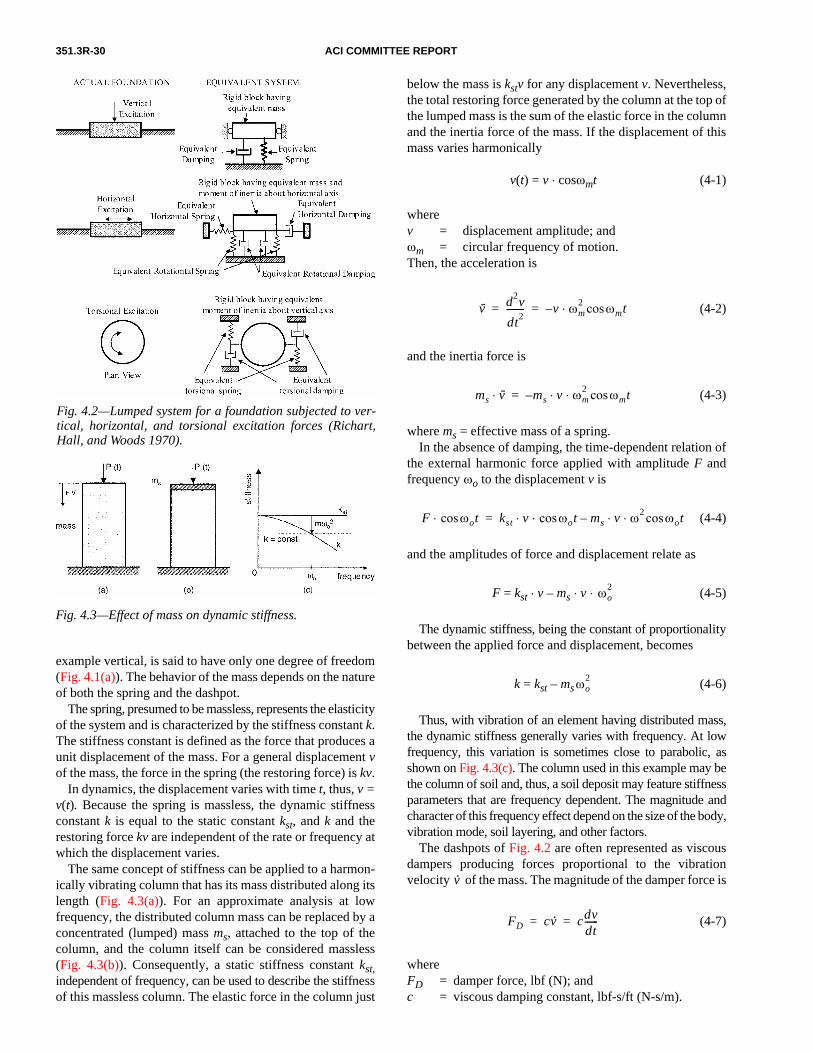
351.3R-30 ACI COMMITTEE REPORT
example vertical, is said to have only one degree of freedom(Fig. 4.1(a)). The behavior of the mass depends on the natureof both the spring and the dashpot.
The spring, presumed to be massless, represents the elasticityof the system and is characterized by the stiffness constant k.The stiffness constant is defined as the force that produces aunit displacement of the mass. For a general displacement vof the mass, the force in the spring (the restoring force) is kv.
In dynamics, the displacement varies with time t, thus, v =v(t). Because the spring is massless, the dynamic stiffnessconstant k is equal to the static constant kst, and k and therestoring force kv are independent of the rate or frequency atwhich the displacement varies.
The same concept of stiffness can be applied to a harmon-ically vibrating column that has its mass distributed along itslength (Fig. 4.3(a)). For an approximate analysis at lowfrequency, the distributed column mass can be replaced by aconcentrated (lumped) mass ms, attached to the top of thecolumn, and the column itself can be considered massless(Fig. 4.3(b)). Consequently, a static stiffness constant kst,independent of frequency, can be used to describe the stiffnessof this massless column. The elastic force in the column just
Fig. 4.2—Lumped system for a foundation subjected to ver-tical, horizontal, and torsional excitation forces (Richart,Hall, and Woods 1970).
Fig. 4.3—Effect of mass on dynamic stiffness.
below the mass is kstv for any displacement v. Nevertheless,the total restoring force generated by the column at the top ofthe lumped mass is the sum of the elastic force in the columnand the inertia force of the mass. If the displacement of thismass varies harmonically
v(t) = v ⋅ cosωmt (4-1)
wherev = displacement amplitude; andωm = circular frequency of motion.Then, the acceleration is
(4-2)
and the inertia force is
(4-3)
where ms = effective mass of a spring.In the absence of damping, the time-dependent relation of
the external harmonic force applied with amplitude F andfrequency ωo to the displacement v is
(4-4)
and the amplitudes of force and displacement relate as
F = kst ⋅ v – ms ⋅ v ⋅ (4-5)
The dynamic stiffness, being the constant of proportionalitybetween the applied force and displacement, becomes
k = kst – ms (4-6)
Thus, with vibration of an element having distributed mass,the dynamic stiffness generally varies with frequency. At lowfrequency, this variation is sometimes close to parabolic, asshown on Fig. 4.3(c). The column used in this example may bethe column of soil and, thus, a soil deposit may feature stiffnessparameters that are frequency dependent. The magnitude andcharacter of this frequency effect depend on the size of the body,vibration mode, soil layering, and other factors.
The dashpots of Fig. 4.2 are often represented as viscousdampers producing forces proportional to the vibrationvelocity of the mass. The magnitude of the damper force is
(4-7)
whereFD = damper force, lbf (N); andc = viscous damping constant, lbf-s/ft (N-s/m).
v·· d2v
dt2-------- v ωm
2 ωmtcos⋅–= =
ms v··⋅ ms v ωm2 ωmtcos⋅ ⋅–=
F ωotcos⋅ kst v ωot ms v ω2 ωotcos⋅ ⋅–cos⋅ ⋅=
ωo2
ωo2
v·
FD cv· cdvdt------= =
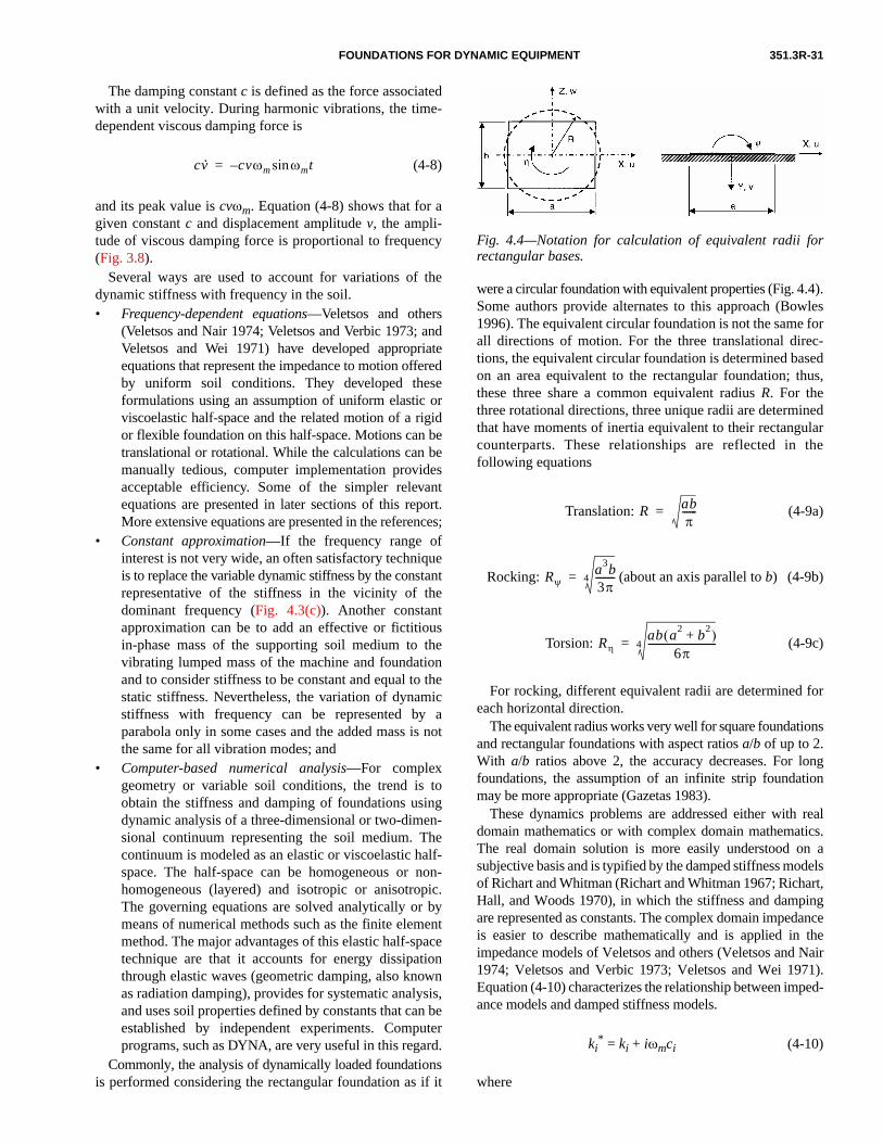
FOUNDATIONS FOR DYNAMIC EQUIPMENT 351.3R-31
The damping constant c is defined as the force associatedwith a unit velocity. During harmonic vibrations, the time-dependent viscous damping force is
(4-8)
and its peak value is cvωm. Equation (4-8) shows that for agiven constant c and displacement amplitude v, the ampli-tude of viscous damping force is proportional to frequency(Fig. 3.8).
Several ways are used to account for variations of thedynamic stiffness with frequency in the soil. • Frequency-dependent equations—Veletsos and others
(Veletsos and Nair 1974; Veletsos and Verbic 1973; andVeletsos and Wei 1971) have developed appropriateequations that represent the impedance to motion offeredby uniform soil conditions. They developed theseformulations using an assumption of uniform elastic orviscoelastic half-space and the related motion of a rigidor flexible foundation on this half-space. Motions can betranslational or rotational. While the calculations can bemanually tedious, computer implementation providesacceptable efficiency. Some of the simpler relevantequations are presented in later sections of this report.More extensive equations are presented in the references;
• Constant approximation—If the frequency range ofinterest is not very wide, an often satisfactory techniqueis to replace the variable dynamic stiffness by the constantrepresentative of the stiffness in the vicinity of thedominant frequency (Fig. 4.3(c)). Another constantapproximation can be to add an effective or fictitiousin-phase mass of the supporting soil medium to thevibrating lumped mass of the machine and foundationand to consider stiffness to be constant and equal to thestatic stiffness. Nevertheless, the variation of dynamicstiffness with frequency can be represented by aparabola only in some cases and the added mass is notthe same for all vibration modes; and
• Computer-based numerical analysis—For complexgeometry or variable soil conditions, the trend is toobtain the stiffness and damping of foundations usingdynamic analysis of a three-dimensional or two-dimen-sional continuum representing the soil medium. Thecontinuum is modeled as an elastic or viscoelastic half-space. The half-space can be homogeneous or non-homogeneous (layered) and isotropic or anisotropic.The governing equations are solved analytically or bymeans of numerical methods such as the finite elementmethod. The major advantages of this elastic half-spacetechnique are that it accounts for energy dissipationthrough elastic waves (geometric damping, also knownas radiation damping), provides for systematic analysis,and uses soil properties defined by constants that can beestablished by independent experiments. Computerprograms, such as DYNA, are very useful in this regard.
Commonly, the analysis of dynamically loaded foundationsis performed considering the rectangular foundation as if it
cv· cvωm ωmtsin–=
were a circular foundation with equivalent properties (Fig. 4.4).Some authors provide alternates to this approach (Bowles1996). The equivalent circular foundation is not the same forall directions of motion. For the three translational direc-tions, the equivalent circular foundation is determined basedon an area equivalent to the rectangular foundation; thus,these three share a common equivalent radius R. For thethree rotational directions, three unique radii are determinedthat have moments of inertia equivalent to their rectangularcounterparts. These relationships are reflected in thefollowing equations
Translation: (4-9a)
Rocking: (about an axis parallel to b) (4-9b)
Torsion: (4-9c)
For rocking, different equivalent radii are determined foreach horizontal direction.
The equivalent radius works very well for square foundationsand rectangular foundations with aspect ratios a/b of up to 2.With a/b ratios above 2, the accuracy decreases. For longfoundations, the assumption of an infinite strip foundationmay be more appropriate (Gazetas 1983).
These dynamics problems are addressed either with realdomain mathematics or with complex domain mathematics.The real domain solution is more easily understood on asubjective basis and is typified by the damped stiffness modelsof Richart and Whitman (Richart and Whitman 1967; Richart,Hall, and Woods 1970), in which the stiffness and dampingare represented as constants. The complex domain impedanceis easier to describe mathematically and is applied in theimpedance models of Veletsos and others (Veletsos and Nair1974; Veletsos and Verbic 1973; Veletsos and Wei 1971).Equation (4-10) characterizes the relationship between imped-ance models and damped stiffness models.
ki* = ki + iωmci (4-10)
where
R abπ
------=
Rψa3b3π--------4=
Rη
ab a2 b2+( )6π
----------------------------4=
Fig. 4.4—Notation for calculation of equivalent radii forrectangular bases.
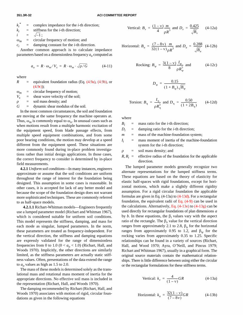
351.3R-32 ACI COMMITTEE REPORT
ki* = complex impedance for the i-th direction;
ki = stiffness for the i-th direction;i = ;ωm = circular frequency of motion; andci = damping constant for the i-th direction.
Another common approach is to calculate impedanceparameters based on a dimensionless frequency ao computed as
(4-11)
whereR = equivalent foundation radius (Eq. (4.9a), (4.9b), or
(4.9c));ωm = circular frequency of motion;Vs = shear wave velocity of the soil;ρ = soil mass density; andG = dynamic shear modulus of the soil.
In the most common circumstances, the soil and foundationare moving at the same frequency the machine operates at.Thus, ωm is commonly equal to ωo. In unusual cases such aswhen motions result from a multiple harmonic excitation ofthe equipment speed, from blade passage effects, frommultiple speed equipment combinations, and from somepoor bearing conditions, the motion may develop at a speeddifferent from the equipment speed. These situations aremore commonly found during in-place problem investiga-tions rather than initial design applications. In those cases,the correct frequency to consider is determined by in-placefield measurements.
4.2.1 Uniform soil conditions—In many instances, engineersapproximate or assume that the soil conditions are uniformthroughout the range of interest for the foundation beingdesigned. This assumption in some cases is reasonable. Inother cases, it is accepted for lack of any better model andbecause the scope of the foundation design does not warrantmore sophisticated techniques. These are commonly referredto as half-space models.
4.2.1.1 Richart-Whitman models—Engineers frequentlyuse a lumped parameter model (Richart and Whitman 1967),which is considered suitable for uniform soil conditions.This model represents the stiffness, damping, and mass foreach mode as singular, lumped parameters. In the norm,these parameters are treated as frequency-independent. Forthe vertical direction, the stiffness and damping equationsare expressly validated for the range of dimensionlessfrequencies from 0 to 1.0 (0 < ao < 1.0) (Richart, Hall, andWoods 1970). Implicitly, the other directions are similarlylimited, as the stiffness parameters are actually static stiff-ness values. Often, presentations of the data extend the rangeto ao values as high as 1.5 to 2.0.
The mass of these models is determined solely as the trans-lational mass and rotational mass moment of inertia for theappropriate directions. No effective soil mass is included inthe representation (Richart, Hall, and Woods 1970).
The damping recommended by Richart (Richart, Hall, andWoods 1970) associates with motion of rigid, circular foun-dations as given in the following equations
1–
ao R ωm Vs⁄⋅ R ωm ρ G⁄⋅ ⋅= =
Vertical: and (4-12a)
Horizontal: and (4-12b)
Rocking: and (4-12c)
Torsion: and (4-12d)
where
Bi = mass ratio for the i-th direction;
Di = damping ratio for the i-th direction;
m = mass of the machine-foundation system;
Ii = mass moment of inertia of the machine-foundationsystem for the i-th direction;
ρ = soil mass density; and
R, Ri = effective radius of the foundation for the applicabledirection.
The lumped parameter models generally recognize twoalternate representations for the lumped stiffness terms.These equations are based on the theory of elasticity forelastic half-spaces with rigid foundations, except for hori-zontal motions, which make a slightly different rigidityassumption. For a rigid circular foundation the applicableformulas are given in Eq. (4-13a) to (4-13d). For a rectangularfoundation, the equivalent radii of Eq. (4-9) can be used inthe calculations. Alternatively, Eq. (4-13e) to (4-13g) can beused directly for rectangular foundations of plan dimensions aby b. In these equations, the βi values vary with the aspectratio of the rectangle. The βv value for the vertical directionranges from approximately 2.1 to 2.8, βu for the horizontalranges from approximately 0.95 to 1.2, and βψ for therocking varies from approximately 0.35 to 1.25. Specificrelationships can be found in a variety of sources (Richart,Hall, and Wood 1970; Ayra, O’Neill, and Pincus 1979;Richart and Whitman 1967), usually in a graphical form. Theoriginal source materials contain the mathematical relation-ships. There is little difference between using either the circularor the rectangular formulations for these stiffness terms.
Vertical: (4-13a)
Horizontal: (4-13b)
Bv1 ν–( )
4---------------- m
ρR3---------= Dv
0.425
Bv
-------------=
Bu7 8ν–( )
32 1 ν–( )----------------------- m
ρR3---------= Du
0.288
Bu
-------------=
Bψ3 1 ν–( )
8--------------------
Iψ
ρRψ
5----------=
Dψ0.15
1 Bψ+( ) Bψ
--------------------------------=
Bη
Iη
ρRη
5----------= Dη
0.501 2Bη+( )
------------------------=
kv4
1 ν–( )----------------GR=
ku32 1 ν–( )
7 8ν–( )-----------------------GR=

FOUNDATIONS FOR DYNAMIC EQUIPMENT 351.3R-33
Rocking: (4-13c)
Torsion: (4-13d)
Vertical: (4-13e)
Horizontal: (4-13f)
Rocking: (4-13g)
(about an axis parallel to b)
whereki = stiffness for the i-th direction;G = shear modulus of the soil;R, Ri = equivalent foundation radius;ν = Poisson’s ratio of the soil;a, b = plan dimensions of a rectangular foundation; andβi = rectangular footing coefficients (Richart, Hall,
and Woods 1970).The damping constants can be determined from the
computed damping ratio, system mass, and stiffness as
or (4-14)
whereci = damping constant for the i-th direction;Di = damping ratio for the i-th direction;ki = stiffness for the i-th direction;m = mass of the machine-foundation system; andIi = mass moment of inertia of the machine-founda-
tion system for the i-th direction.4.2.1.2 Veletsos models—For the impedance functions
of foundations resting on the surface of a viscoelastic half-space, Veletsos and Verbic (1973) determined the analyticalexpressions for impedance dependent on frequency, Poisson’sratio, and internal material damping. Neglecting the internalmaterial damping, the relationships areHorizontal impedance:
(4-15a)
Rocking impedance
(4-15b)
where
kψ8
3 1 ν–( )--------------------GRψ
3=
kη163
------GRη
3=
kvG
1 ν–( )----------------βv ab=
ku 2 1 ν+( )Gβu ab=
kψG
1 ν–( )----------------βψba
2=
ci 2Di kim= ci 2Di kiIi=
ku∗ 8GR
2 v–----------- 1 iaoα1+[ ]=
kψ∗ 8GRψ
3
3 1 v–( )------------------- 1 χψ– β3ao
2–( ) iaoψψ+[ ]=
Vertical impedance
(4-15c)
where
Torsional impedance: (4-15d)
where
whereki
* = impedance in the i-th direction;R, Ri = equivalent foundation radius;G = dynamic shear modulus of the soil;ao = dimensionless frequency;ν = Poisson’s ratio of the soil;α1, βj , and γj = coefficients dependent on Poisson’s ratio
as given in Table 4.1;j = 1 to 4 as appropriate; andb1, b2 = 0.425 and 0.687, respectively (Veletsos
and Nair 1974).The leading terms of each of these impedance equations are
the static stiffnesses of the foundation for motion in thatdirection. For three cases (vertical, rocking, and torsionalmotion), these terms are the same as presented in the Richart-Whitman lumped parameter model. For the horizontal motion,there is a slight difference due to assumptions about thefoundation rigidity. The practicality of the difference is small,especially toward the higher range of Poisson’s ratio values.
These equations may also be expressed as
χψ
β1 β2ao( )2
1 β2ao( )2+---------------------------=
ψψ
β1β2 β2ao( )⋅ 2
1 β2ao( )2+----------------------------------=
kv∗ 4GR
1 ν–( )---------------- 1 χv– γ3ao
2–( ) iao γ4 ψv+( )+[ ]=
χvγ1 γ2ao( )⋅ 2
1 γ2ao( )2+---------------------------=
ψvγ1γ2 γ2ao( )⋅ 2
1 γ2ao( )2+--------------------------------=
kη∗ 16GRη
3
3----------------- A iaoB+[ ]=
A 1b1 b2ao( )2⋅
1 b2ao( )2+----------------------------–=
Bb1b2 b2ao( )2⋅
1 b2ao( )2+---------------------------------=
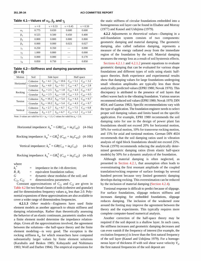
351.3R-34 ACI COMMITTEE REPORT
Horizontal impedance: ku* = GR(Cu1 + iaoCu2) (4-16a)
Rocking impedance: kψ* = GRψ
3 (Cψ1 + iaoCψ2) (4-16b)
Vertical impedance: kv* = GR(Cv1 + iaoCv2) (4-16c)
Rocking impedance: kη* = GRη
3 (Cη1 + iaoCη2) (4-16d)
whereki
* = impedance in the i-th direction;R, Ri = equivalent foundation radius;G = dynamic shear modulus of the soil; andCi1, Ci2 = dimensionless parameters.
Constant approximations of Ci1 and Ci2 are given inTable 4.2 for two broad classes of soils (cohesive and granular)and for dimensionless frequency values ao less than 2.0. Poly-nomial expansions of these approximations are also available tocover a wider range of dimensionless frequencies.
4.2.1.3 Other models—Engineers have used finiteelement models as another approach to obtain stiffness anddamping relationships. Rather than theoretically assessingthe behavior of an elastic continuum, parametric studies witha finite element model determine the impedance relation-ships. Given all the approximations involved, the agreementbetween the solutions—the half-space theory and the finiteelement modeling—is very good. The exception is therocking stiffness kψ for which researchers have computedsubstantially larger values by finite element solutions(Karabalis and Beskos 1985; Kobayashi and Nishimura1983; Wolf and Darbre 1984). The empirical expressions for
Table 4.1—Values of α1, βj, and γj
ν = 0 ν = 0.33 ν = 0.45 ν = 0.50
α1 0.775 0.650 0.600 0.600
β1 0.525 0.500 0.450 0.400
β2 0.800 0.800 0.800 0.800
β3 0.000 0.000 0.023 0.027
γ1 0.250 0.350 — 0.000
γ2 1.000 0.800 — 0.000
γ3 0.000 0.000 — 0.170
γ4 0.850 0.750 — 0.850
Table 4.2—Stiffness and damping parameters(D = 0)
Motion Soil Side layer Half space
HorizontalCohesive Su1 = 4.1 Su2 = 10.6 Cu1 = 5.1 Cu2 = 3.2
Granular Su1 = 4.0 Su2 = 9.1 Cu1 = 4.7 Cu2 = 2.8
RockingCohesive Sψ1 = 2.5 Sψ2 = 1.8 Cψ1 = 4.3 Cψ2 = 0.7
Granular Sψ1 = 2.5 Sψ2 = 1.8 Cψ1 = 3.3 Cψ2 = 0.5
TorsionCohesive Sη1 = 10.2 Sη2 = 5.4 Cη1 = 4.3 Cη2 = 0.7
Granular Sη1 = 10.2 Sη2 = 5.4 Cη1 = 4.3 Cη2 = 0.7
VerticalCohesive Sv1 = 2.7 Sv2 = 6.7 Cv1 = 7.5 Cv2 = 6.8
Granular Sv1 = 2.7 Sv2 = 6.7 Cv1 = 5.2 Cv2 = 5.0
Note: S values are valid for 0.5 < ao < 1.5; C values for valid for ao < 2.0.
the static stiffness of circular foundations embedded into ahomogeneous soil layer can be found in Elsabee and Morray(1977) and Kausel and Ushijima (1979).
4.2.2 Adjustments to theoretical values—Damping in asoil-foundation system consists of two components:geometric damping and material damping. The geometricdamping, also called radiation damping, represents ameasure of the energy radiated away from the immediateregion of the foundation by the soil. Material dampingmeasures the energy loss as a result of soil hysteresis effects.
Sections 4.2.1.1 and 4.2.1.2 present equations to evaluategeometric damping that can be evaluated for various shapefoundations and different types of soils using elastic half-space theories. Both experience and experimental resultsshow that damping values for large foundations undergoingsmall vibration amplitudes are typically less than thoseanalytically predicted values (EPRI 1980; Novak 1970). Thisdiscrepancy is attributed to the presence of soil layers thatreflect waves back to the vibrating foundation. Various sourcesrecommend reduced soil values (EPRI 1980; Novak 1970; DIN4024; and Gazetas 1982). Specific recommendations vary withthe type of application. The foundation engineer needs to selectproper soil damping values and limits based on the specificapplication. For example, EPRI 1980 recommends the soildamping ratio for use in the design of power plant fanfoundations should not exceed 20% for horizontal motion,50% for vertical motion, 10% for transverse rocking motion,and 15% for axial and torsional motions. German DIN 4024recommends that the soil damping ratios used in vibrationanalysis of rigid block foundations should not exceed 25%.Novak (1970) recommends reducing the analytically deter-mined geometric damping ratios (from elastic half-spacemodels) by 50% for a dynamic analysis of the foundation.
Although material damping is often neglected, aspresented in Section 4.2.1, that assumption often leads tooverestimating the first resonant amplitude of the coupledtranslation/rocking response of surface footings by severalhundred percent because very limited geometric dampingdevelops during rocking. This overestimation can be reducedby the inclusion of material damping (Section 4.2.4).
Torsional response is difficult to predict because of slippage.For surface foundations, slippage reduces stiffness andincreases damping; for embedded foundations, slippagereduces damping. The inclusion of the weakened zonearound the footing may improve the agreement between thetheory and the experiments. This typically requires morecomplete computer-based numerical analysis.
Another correction of the half-space theory may berequired if the soil deposit is a shallow layer. In such cases,the stiffness increases and geometric damping decreases andcan even vanish if the frequency of interest (for example, theexcitation frequency) is lower than the first natural frequencyof the soil layer (Kausel and Ushijima 1979). For a homoge-neous layer of thickness H with soil shear wave velocity Vs,the first natural frequencies of the soil deposit are

FOUNDATIONS FOR DYNAMIC EQUIPMENT 351.3R-35
Horizontal direction: (4-17)
Vertical direction: (4-18)
whereωsu, ωsv = circular natural frequencies of a soil layer in u
and v directions;Vs = soil shear wave velocity;H = depth of soil layer; andν = Poisson’s ratio of the soil.
At excitation frequencies ωo lower than ωsu and ωsv, onlymaterial damping remains because no progressive waveoccurs to generate geometric damping in the absence ofmaterial damping, and only a very weak progressive waveoccurs in the presence of material damping. The dampingparameters generated by the material alone to be used forexcitation frequencies ωo lower than ωsu and ωsv are
cu = 2βm ⋅ ku/ωo (4-19)
cv = 2βm ⋅ kv/ωo (4-20)
where βm = material damping ratio, and other terms are aspreviously defined. In the impedance models, the imaginaryterms of the horizontal (ku
*) and vertical (kv*) impedance
become +2βmi within the brackets of Eq. (4-15a) and (4-15c).This correction is most important for the vertical and hori-zontal directions, in which the geometric damping of thehalf-space is high but is minimal for the shallow layer. Thiscorrection is not an absolute breakpoint based on thecomputed layer frequency and the excitation frequency.Short of using computer-based numerical solution tech-niques that reasonably represent the loss of geometricdamping, the foundation engineer should apply judgement todecrease the geometric damping for shallow layer sites.
4.2.3 Embedment effects—Most footings do not rest on thesurface of the soil but are partly embedded. Studies haveshown that embedment increases both stiffness anddamping, but the increase in damping is more significant.
Overall, embedment effects are often overestimatedbecause soil stiffness (shear modulus) diminishes toward thesoil surface due to diminishing confining pressure. This isparticularly so for backfill lacking a stiff surface crust andwhose effects are always much less pronounced than thoseof undisturbed soil. The lack of confining pressure at thesurface often leads to separation of the soil from the foundationand to the creation of a gap as indicated on Fig. 4.5, whichsignificantly reduces the effectiveness of embedment. Tofind an approximate correction for this effect, the engineershould consider an effective embedment depth less than thetrue embedment.
In determining the stiffness of embedded foundations, anapproximate but versatile approach was formulated using theassumption that the soil reactions acting on the base can be
ωsuπVS
2H--------- 2 1 ν–( )
1 2ν–--------------------=
ωsvπVS
2H---------=
taken as equal to those of a surface foundation (half-space)and the reactions acting on the footing sides as equal to thoseof an independent layer overlying the half-space (Fig. 4.5).The evaluation of the reactions of a layer is simplified andcalculated using the assumption of plane strain. This meansthat these reactions are taken as equal to those of a rigid,infinitely long, massless cylinder undergoing a uniformmotion in an infinite homogeneous medium.
The plane strain approach to the side reactions has manyadvantages: it accounts for energy radiation through wavepropagation, leads to closed-form solutions, and allows forthe variation of the soil properties with depth. It can alsoallow for the slippage zone around the footing. Also, theapproach is simple and makes it possible to use the solutionsof surface footings because the effect of the independent sidelayer actually represents an approximate correction of thehalf-space solutions for the embedment effect. Thisapproach works quite well, and its accuracy increases withincreasing frequency.
Equation (4-21a) to (4-21d) describe the side resistance ofthe embedded cylinder, analogous to the surface disc, usingcomplex, frequency-dependent impedance
Horizontal impedance: (4-21a)
Vertical impedance: (4-21b)
Rocking impedance: (4-21c)
Torsional impedance: (4-21d)
wherekei
* = impedance in the i-th direction due to embedment;Gs = dynamic shear modulus of the embedment
(side) material;
keu∗ Gsl Su1 i ao Su2⋅ ⋅+[ ]=
kev∗ Gsl Sv1 i ao Sv2⋅ ⋅+[ ]=
ke ψ∗ GsR ψ
2 l Sψ1 i ao Sψ2⋅ ⋅+[ ]=
ke η∗ GsR η
2 l Sη1 i ao Sη2⋅ ⋅+[ ]=
Fig. 4.5—Schematic of embedded foundation.
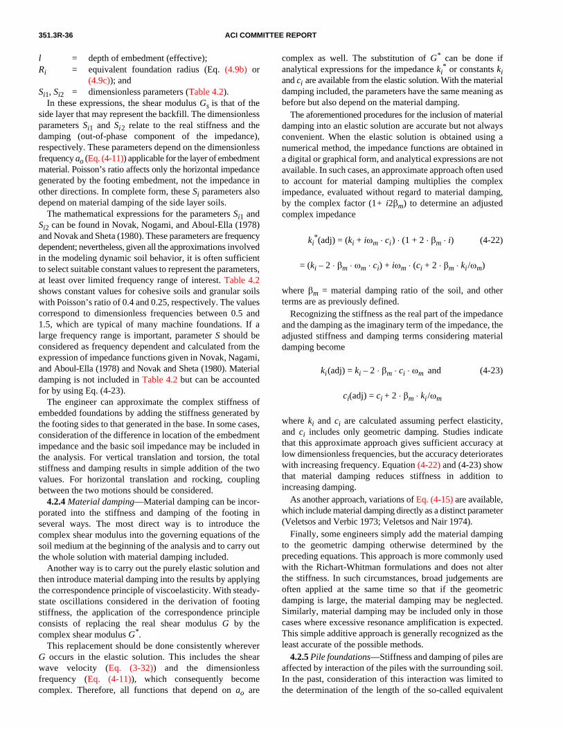
351.3R-36 ACI COMMITTEE REPORT
l = depth of embedment (effective);Ri = equivalent foundation radius (Eq. (4.9b) or
(4.9c)); andSi1, Si2 = dimensionless parameters (Table 4.2).
In these expressions, the shear modulus Gs is that of theside layer that may represent the backfill. The dimensionlessparameters Si1 and Si2 relate to the real stiffness and thedamping (out-of-phase component of the impedance),respectively. These parameters depend on the dimensionlessfrequency ao (Eq. (4-11)) applicable for the layer of embedmentmaterial. Poisson’s ratio affects only the horizontal impedancegenerated by the footing embedment, not the impedance inother directions. In complete form, these Si parameters alsodepend on material damping of the side layer soils.
The mathematical expressions for the parameters Si1 andSi2 can be found in Novak, Nogami, and Aboul-Ella (1978)and Novak and Sheta (1980). These parameters are frequencydependent; nevertheless, given all the approximations involvedin the modeling dynamic soil behavior, it is often sufficientto select suitable constant values to represent the parameters,at least over limited frequency range of interest. Table 4.2shows constant values for cohesive soils and granular soilswith Poisson’s ratio of 0.4 and 0.25, respectively. The valuescorrespond to dimensionless frequencies between 0.5 and1.5, which are typical of many machine foundations. If alarge frequency range is important, parameter S should beconsidered as frequency dependent and calculated from theexpression of impedance functions given in Novak, Nagami,and Aboul-Ella (1978) and Novak and Sheta (1980). Materialdamping is not included in Table 4.2 but can be accountedfor by using Eq. (4-23).
The engineer can approximate the complex stiffness ofembedded foundations by adding the stiffness generated bythe footing sides to that generated in the base. In some cases,consideration of the difference in location of the embedmentimpedance and the basic soil impedance may be included inthe analysis. For vertical translation and torsion, the totalstiffness and damping results in simple addition of the twovalues. For horizontal translation and rocking, couplingbetween the two motions should be considered.
4.2.4 Material damping—Material damping can be incor-porated into the stiffness and damping of the footing inseveral ways. The most direct way is to introduce thecomplex shear modulus into the governing equations of thesoil medium at the beginning of the analysis and to carry outthe whole solution with material damping included.
Another way is to carry out the purely elastic solution andthen introduce material damping into the results by applyingthe correspondence principle of viscoelasticity. With steady-state oscillations considered in the derivation of footingstiffness, the application of the correspondence principleconsists of replacing the real shear modulus G by thecomplex shear modulus G*.
This replacement should be done consistently whereverG occurs in the elastic solution. This includes the shearwave velocity (Eq. (3-32)) and the dimensionlessfrequency (Eq. (4-11)), which consequently becomecomplex. Therefore, all functions that depend on ao are
complex as well. The substitution of G* can be done ifanalytical expressions for the impedance ki
* or constants kiand ci are available from the elastic solution. With the materialdamping included, the parameters have the same meaning asbefore but also depend on the material damping.
The aforementioned procedures for the inclusion of materialdamping into an elastic solution are accurate but not alwaysconvenient. When the elastic solution is obtained using anumerical method, the impedance functions are obtained ina digital or graphical form, and analytical expressions are notavailable. In such cases, an approximate approach often usedto account for material damping multiplies the compleximpedance, evaluated without regard to material damping,by the complex factor (1+ i2βm) to determine an adjustedcomplex impedance
ki*(adj) = (ki + iωm ⋅ ci) ⋅ (1 + 2 ⋅ βm ⋅ i) (4-22)
= (ki – 2 ⋅ βm ⋅ ωm ⋅ ci) + iωm ⋅ (ci + 2 ⋅ βm ⋅ ki /ωm)
where βm = material damping ratio of the soil, and otherterms are as previously defined.
Recognizing the stiffness as the real part of the impedanceand the damping as the imaginary term of the impedance, theadjusted stiffness and damping terms considering materialdamping become
ki(adj) = ki – 2 ⋅ βm ⋅ ci ⋅ ωm and (4-23)
ci(adj) = ci + 2 ⋅ βm ⋅ ki /ωm
where ki and ci are calculated assuming perfect elasticity,and ci includes only geometric damping. Studies indicatethat this approximate approach gives sufficient accuracy atlow dimensionless frequencies, but the accuracy deteriorateswith increasing frequency. Equation (4-22) and (4-23) showthat material damping reduces stiffness in addition toincreasing damping.
As another approach, variations of Eq. (4-15) are available,which include material damping directly as a distinct parameter(Veletsos and Verbic 1973; Veletsos and Nair 1974).
Finally, some engineers simply add the material dampingto the geometric damping otherwise determined by thepreceding equations. This approach is more commonly usedwith the Richart-Whitman formulations and does not alterthe stiffness. In such circumstances, broad judgements areoften applied at the same time so that if the geometricdamping is large, the material damping may be neglected.Similarly, material damping may be included only in thosecases where excessive resonance amplification is expected.This simple additive approach is generally recognized as theleast accurate of the possible methods.
4.2.5 Pile foundations—Stiffness and damping of piles areaffected by interaction of the piles with the surrounding soil.In the past, consideration of this interaction was limited tothe determination of the length of the so-called equivalent

FOUNDATIONS FOR DYNAMIC EQUIPMENT 351.3R-37
cantilever, a freestanding bare pile shorter than the embeddedpile. Pile damping was estimated.
The soil-pile interaction under dynamic loading modifiesthe pile stiffness, making it frequency-dependent. As withshallow foundations, this interaction also generatesgeometric damping. In groups of closely spaced piles, thecharacter of dynamic stiffness and damping is furthercomplicated by interaction between individual piles knownas pile-soil-pile interaction or group effect.
Therefore, recent approaches for determining stiffness anddamping of piles consider soil-pile interaction in terms ofcontinuum mechanics and account for propagation of elasticwaves. The problem solutions are based on a fewapproaches, such as the continuum approach, the lumpedmass model, the finite element model, and the boundaryintegral method (Fig. 4.6).
In most cases, the impedance provided to a pile foundationis determined considering only the effects of the piles.Because piles are typically used due to poor surface layersoils, the effects of the soils directly under the cap are oftenneglected; a settlement gap is assumed to develop. Similarly,the effects of embedment are often neglected. If circumstancesindicate that the embedment effect may be significant, theprocedures outlined in Section 4.2.3 are often applied.
The basic approach toward pile analysis is to first evaluatethe characteristics of a single pile. Once these parameters(stiffness and damping) are established for the single pile,the group effects are determined. Other approaches, such asfinite element analysis, may model and consider both effectssimultaneously.
4.2.5.1 Single piles—Dynamic behavior of embeddedpiles depends on frequency and the properties of both the pileand soil. The pile is described by its length, bending and axialstiffnesses, tip/end conditions, mass, and batter (inclinationfrom the vertical). Soil behavior depends on soil propertiesand the soil’s variation with depth (layering).
Dynamic response of a pile-supported foundation dependson the dynamic stiffness and damping of the piles. Theseproperties for a single pile can be described in terms of eitherimpedance or stiffness and equivalent viscous damping. Aspreviously established, these are related as
ki* = ki + iωmci (4-24)
whereki
* = complex impedance for the i-th direction;
Fig. 4.6—Mathematical models used for dynamic analysisof piles.
ki = stiffness for the i-th direction;i = ;ωm = circular frequency of motion; andci = damping constant for the i-th direction.
The engineer can determine the constants experimentallyor theoretically. The theoretical approach is commonly usedbecause experiments, though very useful, are difficult togeneralize. In the theoretical approach, dynamic stiffness isgenerated by calculating the forces needed to produce a unitamplitude vibration of the pile head in the prescribed direction(Fig. 4.7).
For a single pile, the impedance at the pile head can bedetermined from the following
Vertical translation: (4-25a)
and
Horizontal translation: (4-25b)
and
Rotation of the pile head in the vertical plane:
and (4-25c)
Coupling between horizontal translation and rotation:
and (4-25d)
Torsion: and (4-25e)
wherekij = stiffness of pile j in the i-th direction;
1–
kvjEpAp
ro
------------fv1=
cvjEpAp
VS
------------fv2=
kujEpIp
ro3
----------fu1=
cujEpIp
ro2VS
-----------fu2=
kψjEpIp
ro
----------fψ1= cψjEpIp
VS
---------- fψ2=
kuψjEpIp
R2----------fuψ1= cuψj
EpIp
roVs
----------fuψ2=
knjGpJ
ro
---------fη1= cnjGpJ
Vs
---------fη2=
Fig. 4.7—Generation of pile stiffness in individual directions.

351.3R-38 ACI COMMITTEE REPORT
cij = equivalent viscous damping of pile j in the i-thdirection;
Ep = Young’s modulus of the pile;Ap = cross-sectional area of the pile;Ip = moment of inertia of the pile cross section;ro = pile radius or equivalent radius;Gp J = torsional stiffness of the pile;Vs = shear wave velocity of the soil; andfi1, fi2 = dimensionless stiffness and damping functions
for the i-th direction.Graphical or tabular presentations of the fi1 and fi2 functions
are presented in a variety of sources (Novak 1974, 1977;Kuhlmeyer 1979a,b) and are included in some softwarepackages. If the pile heads are pinned into the foundationblock, then kψ = kuψ = kη = 0 and cψ = cuψ = c η = 0 in theprevious formulas, and ku should be evaluated for pinnedhead piles. The vertical constants labeled v are the same forthe fixed and pinned heads. The rotational parameters (fψ1,fψ2, fuψ1, fuψ2, fη1, and fη2) are applicable only if the pile isassumed or designed to be rotationally fixed to the pile cap.In general, the fi1 and fi2 functions depend on the followingdimensionless parameters:• Dimensionless frequency ao = ωmro/Vs (note that this
value is calculated using the pile radius and is a muchsmaller value than the ao calculated for a complete soilsupported foundation);
• Relative stiffness of the soil to the pile, which can bedescribed either by the modulus ratio G /Ep or thevelocity ratio Vs/Vc in which Vc is the compressionwave velocity of the pile equal to with ρp equalto the pile mass density;
• The mass ratio ρ /ρp of the soil and the pile;• The slenderness ratio lp/ro in which lp is pile length;• Material damping of both soil and pile;• The pile’s tip restraint condition and rotational fixity of
the head; and• Variation of soil and pile properties with depth.
These factors affecting the functions f are not of equalimportance in all situations. Often, some of them can beneglected, making it possible to present numerical values offunction f in the form of tables and charts for some basic cases.
The pile stiffness diminishes with frequency quickly if thesoil is very weak relative to the pile. This happens when thesoil shear modulus is very low or when the pile is very stiff.In addition, dynamic stiffness can be considered practicallyindependent of frequency for slender piles in average soil.
The imaginary part of the impedance (pile damping)grows almost linearly with frequency and, therefore, can berepresented by constants of equivalent viscous damping ci ,which are also almost frequency independent. Only belowthe fundamental natural frequencies of the soil layer Eq. (4-17)and (4-18) does geometric damping vanish and materialdamping remain as the principal source of energy dissipation.Then soil damping can be evaluated using Eq. (4-19) and(4-20). The disappearance of geometric damping may beexpected with low frequencies and shallow layers, stiff soils,or both. Apart from these situations, frequency independent
Ep ρp⁄
viscous damping constants, and functions fi2, which definethem, are sufficient for practical applications.
The mass ratio ρ/ρp is another factor whose effect islimited to extreme cases. Only for very heavy piles do thepile stiffness and damping change significantly with themass ratio.
The Poisson’s ratio effect is very weak for vertical vibration,absent for torsion, and not very strong for the other mode ofvibration, unless the Poisson’s ratio approaches 0.5 andfrequencies are high. The effect of Poisson’s ratio on param-eters fi1 and fi2 can be further reduced if the ratio E/Ep ratherthan G/Ep is used to define the stiffness ratio.
The slenderness ratio, lp/ro, and the tip conditions are veryimportant for short piles, particularly for vertical motionbecause the piles are stiff in that direction. Floating piles(also called friction piles) have lower stiffness but higherdamping than end bearing piles. In the horizontal direction,piles tend to be very flexible. Consequently, parameters fi1and fi2 become practically independent of pile length and thetip condition for ratios lp/ro greater than 25 if the soilmedium is homogeneous.
Observations suggest that the most important factorscontrolling the stiffness and damping functions fi1 and fi2 arethe stiffness ratio relating soil stiffness to pile stiffness, the soilprofile, and, for the vertical direction, the tip restraint condition.
4.2.5.2 Pile groups—Piles are usually used in a group.The behavior of a pile group depends on the distance betweenindividual piles. When the distance between individual piles islarge—20 diameters or more—the piles do not affect eachother, and the group stiffness and damping are the sums ofthe contributions from the individual piles. If, however, thepiles are closely spaced, they interact with each other. Thispile-soil-pile interaction or group effect exerts a consider-able influence on the stiffness and damping of the group.These two basic situations may be treated separately.
Pile interaction neglected—When spacing between pilesreaches 20 diameters or more, the interaction between pilescan be neglected. Then stiffness and damping of the pilegroup can be determined by the summation of stiffness anddamping constants of the individual piles. In many cases,initial calculations are performed neglecting the interaction.An overall group efficiency factor is then determined andapplied to the summations.
In the vertical and horizontal directions, the summation isstraightforward. For torsion and sliding coupled withrocking, the position of the center of gravity CG and thearrangement of the piles in plan are important. Thus, thegroup stiffness and damping with respect to rotation derivefrom the horizontal, vertical, and moment resistance of indi-vidual piles and the pile layout.
As the rigid body is rotated, an amount ψ at the CG (Fig. 4.8),the head of pile j undergoes horizontal translation uj =ψyj,vertical translation vj =ψxj, and rotation ψj = ψ. For thetorsional stiffness and damping of the group, the twist ηapplied at the CG twists the pile by the same angle andtranslates its head horizontally by the distance equals to
(Fig. 4.9). With these considerations and notationsshown on Fig. 4.8 and 4.9, the stiffness and damping constantsη xj
2 zj2+

FOUNDATIONS FOR DYNAMIC EQUIPMENT 351.3R-39
of the pile group for individual motions as referenced to thecentroid of the pile group are as follows
Vertical translation: and (4-26a)
Horiztonal translation:
and (4-26b)
Rotation of the cap in the vertical plane:
and (4-26c)
Coupling between horizontal translation and rotation:
and (4-26d)
Torsion about vertical axis:
and (4-26e)
wherekgi = pile group stiffness in the i-th direction; andcgi = pile group damping in the i-th direction.
The summations extend over all the piles. The distances xjand zj refer to the distances from the centroid of the pilegroup to the individual pile. If the CG is located directlyabove the pile group centroid, these distances are as indi-cated in Fig. 4.8 and 4.9. The vertical eccentricity yc must beaddressed as presented in Section 4.2.6. These stiffness anddamping terms, or their impedance equivalents, representvalues comparable to the terms developed for a soil-supported foundation in Section 4.2.1.
Pile interaction considered—When piles are closelyspaced, they interact with each other because the displacement
kgv kvj
j 1=
N
∑= cgv cvj
j 1=
N
∑=
kgu kuj
j 1=
N
∑= cgu cuj
j 1=
N
∑=
kg ψ k ψj kvj xj2+( )
j 1=
N
∑=
cg ψ c ψj cvj xj2+( )
j 1=
N
∑=
kgu ψ kg ψu ku ψj
j 1=
N
∑= =
cgu ψ cg ψu cu ψj
j 1=
N
∑= =
kg η knj kuj xj2
zj2+( )+[ ]
j 1=
N
∑=
cg η cnj cuj xj2 zj
2+( )+[ ]j 1=
N
∑=
of one pile contributes to the displacements of others.Studies of these effects call for the consideration of the soilas a continuum.
For static loads, these studies indicate that the main resultsof the static pile interaction are an increase in settlement ofthe group, a redistribution of the pile stresses, and, with rigidcaps, a redistribution of pile reactions.
The studies of the dynamic pile-soil-pile interactionsuggest a number of different observations:• Dynamic group effects are profound and differ consid-
erably from static group effects;• Dynamic stiffness and damping of piles groups vary
with frequency, and these variations are more dramaticthan with single piles; and
• Group stiffness and damping can be either reduced orincreased by pile-soil-pile interaction.
These effects can be demonstrated if the group stiffnessand damping are described in terms of the group efficiencyratio GE defined as
Fig. 4.8—Pile displacements for determination of groupstiffness and damping related to unit rotation ψ.
Fig. 4.9—Pile displacements for determination of groupstiffness and damping related to unit torsion η.
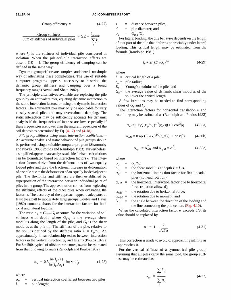
351.3R-40 ACI COMMITTEE REPORT
Group efficiency = (4-27)
= GE =
where kr is the stiffness of individual pile considered inisolation. When the pile-soil-pile interaction effects areabsent, GE = 1. The group efficiency of damping can bedefined in the same way.
Dynamic group effects are complex, and there is no simpleway of alleviating these complexities. The use of suitablecomputer programs appears necessary to describe thedynamic group stiffness and damping over a broadfrequency range (Novak and Sheta 1982).
The principle alternatives available are replacing the pilegroup by an equivalent pier, equating dynamic interaction tothe static interaction factors, or using the dynamic interactionfactors. The equivalent pier may only be applicable for veryclosely spaced piles and may overestimate damping. Thestatic interaction may be sufficiently accurate for dynamicanalysis if the frequencies of interest are low, especially ifthese frequencies are lower than the natural frequencies of thesoil deposit as determined by Eq. (4-17) and (4-18).
Pile group stiffness using static interaction coefficients—An accurate analysis of static behavior of pile groups shouldbe performed using a suitable computer program (Sharnoubyand Novak 1985; Poulos and Randolph 1983). Nevertheless,a simplified approximate analysis suitable for hand calculationscan be formulated based on interaction factors α. The inter-action factors derive from the deformations of two equallyloaded piles and give the fractional increase in deformationof one pile due to the deformation of an equally loaded adjacentpile. The flexibility and stiffness are then established bysuperposition of the interaction between individual pairs ofpiles in the group. The approximation comes from neglectingthe stiffening effects of the other piles when evaluating thefactor α. The accuracy of the approach appears adequate, atleast for small to moderately large groups. Poulos and Davis(1980) contains charts for the interaction factors for bothaxial and lateral loading.
The ratio ρa = Gave /Gl accounts for the variation of soilstiffness with depth, where Gave is the average shearmodulus along the length of the pile, and Gl is the shearmodulus at the pile tip. The stiffness of the pile, relative tothe soil, is defined by the stiffness ratio λ = Ep/Gl. Anapproximately linear relationship exists between interactionfactors in the vertical direction αv and ln(s/d) (Poulos 1979).For λ ≅ 500, typical of offshore structures, αv can be estimatedfrom the following formula (Randolph and Poulos 1982)
for s ≤ lp (4-28)
whereαv = vertical interaction coefficient between two piles;lp = pile length;
Group stiffnessSum of stiffness of individual piles------------------------------------------------------------------------------------
kgroup
krr∑--------------
αv 0.5lp s⁄( )ln
lpdρa( )ln-----------------------=
s = distance between piles;d = pile diameter; andρa = Gave/Gl.
For lateral loading, the pile behavior depends on the lengthof that part of the pile that deforms appreciably under lateralloading. This critical length may be estimated from theformula (Randolph 1981)
lc = 2ro(Ep/Gc)2/7 (4-29)
wherelc = critical length of a pile;ro = pile radius;Ep = Young’s modulus of the pile; andGc = the average value of dynamic shear modulus of the
soil over the critical length.A few iterations may be needed to find corresponding
values of Gc and lc.The interaction factors for horizontal translation u and
rotation ψ may be estimated as (Randolph and Poulos 1982)
αuf = 0.6ρc(Ep/Gc)1/7(ro/s)(1 + cos2β) (4-30a)
αuH = 0.4ρc(Ep/Gc)1/7(ro/s)(1 + cos2β) (4-30b)
αψH = and αψM = (4-30c)
whereρc = Gz/GcGz = the shear modulus at depth z = lc /4;αuf = the horizontal interaction factor for fixed-headed
piles (no head rotation);αuH = the horizontal interaction factor due to horizontal
force (rotation allowed);αψH = the rotation due to horizontal force;αψM = the rotation due to moment; andβp = the angle between the direction of the loading and
the line connecting the pile centers (Fig. 4.10).When the calculated interaction factor α exceeds 1/3, its
value should be replaced by
(4-31)
This correction is made to avoid α approaching infinity ass approaches 0.
For the vertical stiffness of a symmetrical pile group,assuming that all piles carry the same load, the group stiff-ness may be estimated as
(4-32)
αuH2 αuH
3
α′ 1 2
27α--------------–=
kgv
kvjj∑
αvj∑-------------=

FOUNDATIONS FOR DYNAMIC EQUIPMENT 351.3R-41
in which kvj is the vertical stiffness of a single pile, and αv isthe interaction factor between a reference pile i and any otherpile in the group. The summation in the denominator thenrepresents a summation of factors between the reference pileand all other piles in the group. The reference pile should notbe in the center or at the periphery and has an interactionfactor with itself of αv = 1.
If a rigid cap is assumed, which implies the same displace-ments for all piles, the piles have different individual stiffnessvalues and the following formula is applied (Novak 1979)
(4-33)
whereεir = the elements of the inverted matrix [αir]
–1; and[αir] = matrix of factors between any two piles with diag-
onal terms αii = 1.The difference between the two previous formulas for kgv
is usually not great. For horizontal stiffness, the approximatecorrection may be done in a similar fashion using factors αufor αuH.
For rotation of a thin rigid cap, the rocking stiffness comesprimarily from the vertical stiffness of the piles. This part ofthe group stiffness becomes
(4-34)
in which x is the horizontal distance of the pile from the axisof rotation. For thick caps, these corrections can be intro-duced into the equations of the rotation of the cap in thevertical plane—the case where pile interaction is neglected.
For torsion of the cap, ignoring the contribution fromindividual pile twisting, the group stiffness can be writtenanalogously as
(4-35)
in which x and z are the pile coordinates indicated in Fig. 4.9.If αir(x) and αir(z) are horizontal interaction factors betweenpiles i and r in direction X and Z, respectively, εir are theelements in [εir] = [αir]
–1.The static procedure does not offer any guidance as to the
effect of interaction on group damping. Group interactionusually increases the damping ratio, not necessarily the dampingconstant c. To account for this approximately, the group
damping constants may be taken as cg ≅ . Better estimates
may be obtained using dynamic interaction coefficients.Evaluation of group effects using dynamic interaction
coefficients—The dynamic interaction factor αij is a dimen-sionless, frequency-dependent, complex number
(4-36)
kgv kvj εirr∑
i∑=
kg ψ kv εirxixrr∑
i∑=
kηη ku εir x( )zizr εir z( )xixrr∑
i∑+
r∑
i∑
=
crr∑
αij∗ αij 1( ) i αij 2( )⋅+= =
in which the displacement of Pile 2 is caused by a unitharmonic load of Pile 1, and the static displacement of Pile 1 isestablished for an isolated pile. The displacement means eithera translation or rotation. These dynamic interaction factors areused in association with stiffness and damping of single pilesin the same way that static interaction factors are used.
The use of dynamic interaction factors yields complexgroup stiffness kg
* = kg + ik2 whose imaginary part definesthe group damping constant cg = k2/ωm. An increase indamping and strong variation with frequency is oftenobtained. Mitwally and Novak (1987) describe a derivationof all the complex stiffness constants for flexible caps, rigidcaps, and piles with separation (gapping).
4.2.5.3 Battered piles—Pile batter can be considered bycalculating the pile stiffnesses for a vertical pile, assemblingthe stiffnesses as the stiffness matrix [K] in element coordi-nates (along and perpendicular to the axis of the pile), andtransforming this matrix into horizontal and vertical globalcoordinates (Novak 1979). This gives the pile stiffness matrix
[k′]j = [T]T[k]j[T] (4-37)
in which the transformation matrix [T] depends on directioncosines from the batter. The horizontal and vertical stiff-nesses for the individual battered pile can then be combinedwith the other pile stiffnesses as presented in Section 4.2.5.2for pile groups.
When the horizontal coordinate axis lies in the plane of thebatter, the transformation matrix is
(4-38)
where α = the angle between the battered pile and vertical.The pile stiffness matrix in global coordinates becomes
(4-39)
Dynamic displacement of Pile 2Static displacement of Pile 1
-----------------------------------------------------------------------------
T[ ]αcos αsin 0
αsin– αcos 0
0 0 1
=
ku′ kuv′ ku ψ′
kvu′ kv′ kv ψ′
kψu′ kψv′ kψ′
=
kucos2 α( ) kvsin2
α( )+ α( ) α( ) ku kv–( )sincos α( )ku ψcos
α( ) α( ) ku kv–( )sincos kusin2 α( ) kvcos2
α( )+ α( )kuψsin
α( )k ψucos α( )k ψusin kψ
Fig. 4.10—Definitions of s and βp.

351.3R-42 ACI COMMITTEE REPORT
The element stiffness functions k are calculated assumingthat the pile is vertical, thus
kuv = kψv = kvψ = 0 and kuψ = kψu (4-40)
In some cases, the off-diagonal terms of the transformedstiffness matrix may be ignored and only the diagonal termscarried forward. One criterion for this is if the off-diagonalterms are small in comparison to the diagonal terms (forexample, less than 10% on an absolute value comparison).The same process may be applied to the damping terms, or,for more accuracy, the transformation can take place usingthe complex impedance functions.
4.2.6 Transformed impedance relative to center of gravity—A machine foundation implies a body of certain depth, and,typically, the center of gravity of the system is above the centerof resistance provided by the soil, embedment, piles, and anycombination of these. For simplicity of analysis, many founda-tions are treated as a rigid body, and their center of gravity isused as the point of reference for all displacements androtations. Thus, stiffness or impedance provided by the supportsystem (piles, isolation springs, soil, or soil embedment) has tobe transformed to reflect resistance provided against motionsof the center of gravity. In this analysis, a horizontal translationis resisted not only by horizontal soil reactions but also bymoments. This gives rise to a coupling between translation androtation and the corresponding “off-diagonal” or cross stiffnessand damping constants such as kuψ = kψu and cuψ = cψu.Double subscripts are used to indicate coupling. (Note thatEq. (4-25d) and (4-25e) also introduced coupling of terms.)
For coupled horizontal and rocking motions, the generationof the stiffness and damping constants is developed as shownin Fig. 4.11. By applying unit translations to a free body of thefoundation, examining the forces developed in the supportsystem by the translation, and determining the forces neededto cause this unit translation, the coupled impedances can be
Fig. 4.11—Coupling effect introduced by an elevated CG.
determined with respect to the center of gravity. Fig. 4.11 ispresented for a simple system where both embedment andbottom support are provided. Evaluation of the forcesassociated with free-body movements yields an impedancematrix for the system with respect to the center of gravity of
(4-41)
whereKij
* = impedance in the i-th direction due to a displace-ment in the j-th direction;
yc = distance from the CG to the base support;ye = distance from the CG to the level of embedment
resistance; andother terms are as previously defined.
If the CG is not directly over the center of vertical impedance,additional coupling terms between the rotation and the verticalmotion are introduced. Thus, most engineers diligently adhereto guidelines to minimize such in-plan eccentricities. Inextreme cases, it may be appropriate to develop the K*
matrix as a full six-by-six matrix due to eccentricities. Forother combinations of directions in other coordinate systems,the sign on the off-diagonal terms may change, so properdiligence to sign convention is required. This transformationto the CG may be developed on stiffness and damping termsor based on impedance.
4.3—Vibration analysis4.3.1 Foundation stiffness—For a concrete block foundation
on grade, when the foundation block is thick enough, thefoundation block can be considered rigid; a formula used forthis judgement is
T > 2 + LB /30 (SI: T > 0.6 + LB /30) (4-42)
where T is the foundation thickness in ft (m), and LB is thegreater plan dimension of the foundation block in ft (m).Otherwise, the foundation block is considered flexible in thevibration analysis.
Equation (4-42) is based on engineering judgement andthe industry practice for some traditional block-type founda-tions (Fig. 2.4). The applicability of Eq. (4-42) to largecombined block foundations (Fig. 2.5) is not well establishedand may need to be investigated by the engineer on a case-by-case basis. Finite element dynamic analysis shows thatsome of these large combined block foundations may notbehave as rigid foundations. Analysis of the frequency anddynamic response of such foundations using the finiteelement methods given in Section 4.3.5 may be appropriate.
K∗uu K∗u ψ
K∗u ψ K∗ψψ
=
k∗u k∗eu+ k∗u yc k∗eu ye+( )–
k∗u yc k∗eu ye+( )– k∗ψ k∗u yc
2 k∗eu ye2+ +

FOUNDATIONS FOR DYNAMIC EQUIPMENT 351.3R-43
In many applications, concrete provides the required inertialmass so that foundations are often massive and rigid. This, inconjunction with the rigid nature of many machines, cangreatly simplify dynamic analysis of the machine-foundationsystem. For equipment on a rigid foundation, when the positionof all parts of the system can be described by a single variableat any time, the system can be accurately represented by aSDOF model. For example, pure vertical or torsional motion ofa rigid system can be accurately represented by a SDOF model.
Nevertheless, in most rigid machine-foundation systems,the horizontal motion is coupled with the rocking motion dueto the system center of gravity (CG) being at one height andthe center of resistance (CR) being at a different level. A twoDOF model represents the coupled response of the systemfor this condition. In general, a six DOF (degree of freedom)model is needed to properly represent the dynamic perfor-mance of a rigid machine-foundation system. If the foundationis well laid out so that the CG and the CR are positioned overeach other (vertically aligned), then the six DOF modelmathematically uncouples to become two problems of twoDOF (rocking about one horizontal axis coupled with trans-lation along the other horizontal axis for both horizontaldirections) and two SDOF problems (vertical motion andtorsional motion about the vertical axis).
4.3.2 Single degree-of-freedom system—For a SDOFsystem, a closed form solution yields the fundamentalnatural frequency as
(4-43)
wherefn = system natural frequency in cycles/second;k = the dynamic stiffness provided by the supporting
media obtained in accordance with Section 4.2, thespring constant of the system; and
m = mass of the machine-foundation system.If the particular SDOF system under investigation
involved rotational motions, the stiffness term in Eq. (4-43)would be the applicable rocking or torsional stiffness and themass term would be a mass moment of inertia. Thus, thestiffness and mass terms are specifically associated with aspecific direction of motion of the machine-foundationsystem. The calculated natural frequency is then comparedwith operating frequencies of the machine to ensure that thefrequency criteria as set forth in Section 3.4 are satisfied.
A forced response analysis is performed to determineamplitudes of vibration. The forced response analysis can bea harmonic analysis if the forcing function is harmonic. Aclosed form solution for a harmonically excited SDOFsystem yields
(4-44)
where
fn1
2 π⋅---------- k m⁄=
AFo k⁄
1 ωo ωn⁄( )2–( )2
2βωo ωn⁄( )2+
---------------------------------------------------------------------------------=
A = displacement amplitude;Fo = dynamic force amplitude;k = the dynamic stiffness provided by the supporting
media;ωo = circular operating frequency of the machine (rad/s); ωn = circular natural frequency of the machine-foundation
system = (k/m)1/2; andβ = system damping ratio = ci /[2(k/m)1/2].
A SDOF analysis can be a very effective tool in designinga rigid foundation. When used in conjunction with a para-metric study the use of a SDOF in the direction of interestcan often bound the solution. Furthermore, the use of anapproximate SDOF analysis can show the feasibility of satis-fying particular vibration criteria and can provide a roughcheck on more-detailed analysis.
4.3.3 Two degree-of-freedom system—As mentionedearlier, a SDOF system may not be sufficient to represent arigid machine-foundation system. For example, a dynamicforce from a rotating machine acting on shaft supports causestranslation and rocking motions of the system, and a two DOFsystem is a more accurate representation of the system. For atwo DOF system, the following frequency equation can beused in solving for the two natural frequencies
(4-45)
whereωn = natural frequencies of the system;Iψ = mass moment of inertia of the system about the CG;m = mass of the machine-foundation system;Kuu = horizontal spring constant Eq. (4-41);Kuψ = coupling spring constant Eq. (4-41); andKψψ = rocking spring constant Eq. (4-41).
Amplitudes of motion for the two DOF can be calculatedin a manner similar to Eq. (4-44) as a modal combination.When rotational (rocking or torsional) motions of the foun-dation exist, it is important to compute displacements at thekey points of interest machine bearings, for example, bycombining the rotational effects with the translationalmotions. These combined motions may be less than orgreater than the motions of the CG, which are determinedthrough the modal combination.
4.3.4 Three or more degree-of-freedom system—Exceptfor cases described in Sections 4.3.2 and 4.3.3, machinessupported on flexible or even rigid foundations generally cannot be adequately represented by a single or two DOF model,and a three or more DOF system should be used.
4.3.4.1 Mathematical models—The physical structure canbe simplified and represented by a mathematical model fordynamic analysis. The model should include the machine,structure, and stiffnesses of supporting medium (soil or piles).The current state-of-the-art in machine foundation design islimited to linearly elastic theory; nonlinear behavior generallyis not considered in routine foundation design.
4.3.4.2 Frequency analysis—A frequency analysis isperformed on the mathematical model to calculate natural
ωn4 Kuu
m--------
Kψψ
Iψ----------+ ωn
2 Kuu Kψψ Kuψ2–⋅
m Iψ⋅---------------------------------------+⋅– 0=

351.3R-44 ACI COMMITTEE REPORT
frequencies and mode shapes of the system. This calculationis also called normal mode or free vibration analysis. Thegeneral dynamic equation of motion is
(4-46)
where[M] = mass matrix;[C] = damping matrix;[K] = stiffness matrix; andF(t) = time varying force vector.
In Eq. (4-46), X and its derivatives represent displacement,velocity, and acceleration, respectively, of various points onthe machine-foundation system.
For a frequency analysis, the force and damping terms areset to zero. The equation of motion reduces to:
(4-47)
Using the normal mode substitutions (common to allclassical vibration analysis such as in: Arya, O’Neill, andPincus 1979; Harris 1996), the following equation is developed
(4-48)
where[k] = reduced stiffness matrix;[m] = reduced mass matrix;ωi = circular natural frequency for the i-th mode; andΨi = reduced mode shape vector for the i-th mode.
Solving Eq. (4-48), the natural frequencies (eigenvalues)and mode shapes (eigenvectors) are obtained. An examinationis then made to determine how the frequencies associatedwith the excitation forces generated by machine operationmatch up with the natural frequencies of the system. If theseoperating frequencies are close to the computed systemnatural frequencies, a resonance condition exists. Section3.4.3 discusses the criteria for frequency separation.
4.3.4.3 Forced response analysis—In the forcedresponse analysis, Eq. (4-46) is solved for X, the displace-ments of the machine-foundation system as a function oftime. The forced response analysis can take the form of aharmonic frequency analysis or a time history analysis. Theselection of method depends on the forcing functions to beevaluated. For the analysis of rotating or reciprocatingmachinery foundations, the harmonic analysis method isused extensively to determine the steady-state response of alinear structure to a set of given harmonic loads.
Harmonic analysis can be carried out either by direct solutionof the equations of motion or by mode superposition tech-niques. In the direct solution method, the equations of motioncan be solved in the time domain. This method does not requirea natural frequency analysis (Eq. (4-47) and (4-48)). Thisnumerical method is more general and flexible than themode superposition method. In the mode superpositionmethod, a natural frequency analysis is performed first. The
M[ ]X·· t( ) C[ ]X· t( ) K[ ]X t( )+ + F t( )=
M[ ]X·· t( ) K[ ]X t( )+ 0=
k[ ] ωi2 m[ ]–( ) Ψi⋅ 0=
forced response analysis is then carried out on a mode-by-mode basis, in some cases for a limited number of modes.These modal results are summed to obtain forced responseanalysis results. The summation may consider the phaserelationship between the modes or may conservativelyconsider only the amplitudes of the modal responsesdepending on the level of accuracy desired.
The results of the forced response analysis includedisplacements, velocities, and accelerations. These resultsare then compared against allowable limits for acceptance.The allowable limits are typically applicable at discretelocations (for example, the equipment bearing, connectionsto adjacent equipment, and locations where people may beaffected). For these multi-DOF models representing structuraland machine flexibility, the modeling commonly includesnode representations for the locations of interest. The analysisshould account for variation in parameters such as structuralstiffness, mass, and soil properties.
4.3.5 Dynamic analysis using computer codes—Althoughit is possible to calculate frequencies and responses of amachine-foundation system using equations, practicingengineers find it is often impractical and inefficient to do so,especially for flexible systems with multiple DOF. Manycommercially available computer codes, such as ANSYS,DYNA, GTSTRUDL, RISA, SACS, SAP2000, andSTAAD, can be used to perform these tasks.
In the computer application, structural beams and columnsare generally represented by prismatic elastic members, andconcrete floors and mats are represented by plates or solidelements. Stiffnesses of the foundation soil or piles should beproperly included in the model to take into account the soil-structure interaction effects. Section 4.2 discusses theimpedance of the supporting media. The machine can bequite stiff compared with the structural members. If so, themachine can be represented by a mass point or pointsconcentrated at their centers of gravity and connected to theirsupports using rigid links. Solid elements with matchingdensities can also be used to simulate the mass and massmoment of inertia of the machine. If the equipment is not sostiff as compared with the structural members, as is the casefor many large gas compressors, its flexibility should beincluded in the computer model representation.
4.4—Structural foundation design and materials4.4.1 Reinforced concrete—The basic principles of
reinforced concrete design embodied in ACI 318 are used inthe design of foundations supporting dynamic equipment.Engineers working with specific equipment may applyadditional criteria based on their experience. Such equipmentincludes forging hammers, turbine-generator systems, andlarge compressors.
The general equipment foundation includes some compo-nents that primarily act in flexure, others that are primarilyaxial, and others may act primarily in shear. Applicablesections of ACI 318 are often used to establish minimumrequirements for axial, flexural, and shear reinforcement. Insome cases, engineering firms have supplemented thesecriteria with internal criteria or internal interpretations of

FOUNDATIONS FOR DYNAMIC EQUIPMENT 351.3R-45
ACI 318 requirements. Such steps are taken for foundationstructures that are very different from conventional buildingstructures (for example, turbine-generator pedestals). Forthick sections, special criteria involving location of reinforcingor minimum reinforcing may be identified more in line withmass concrete construction. Such criteria are typically structurespecific (for example, only for turbine-generator pedestals oronly for foundation slabs over 6 ft (1.8 m) thick) and, thus,are not extendable to the broad class of foundationsaddressed in this document.
Largely because of the broad range represented in thisclass of construction, accepted standards have not evolved.For example, there is no specific minimum amount ofreinforcement applicable across the board for these designs.In some applications, building code requirements may applyand machine manufacturers may set minimum standards. Aminimum concrete strength of 3000 psi (21 MPa) can beapplied. For most foundations and foundations supportingAPI equipment, a strength of 4000 psi (28 MPa) iscommonly specified and may be required. In most cases, thequality and durability of the concrete is considered more criticalto good performance than strength.
As with most construction, ASTM A 615 Grade 60reinforcing steel is most commonly used for dynamicmachine foundations. Good design practice requires particularattention to the detailing of the reinforcement, includingproper development of the bars well into the block of theconcrete, avoidance of bar ends in high stress regions, andappropriate cover. Excessive reinforcement can createconstructibility and quality problems and should be avoided.Some firms specify a minimum reinforcing of 3.1 lbf/ft3
(50 kg/m3 or 0.64%) for piers (machine support pedestals)and 1.9 lbf/ft3 (30 kg/m3 or 0.38%) for foundation slabs. Forcompressor blocks, some firms suggest 1% reinforcing byvolume and may post-tension the block (Section 4.4.1.5).Many engineers recommend additional reinforcement, suchas hairpin bars, around embedded anchor bolts to ensurelong-term performance. The criteria and presentations inACI 351.2R for static equipment also can be applied todynamic equipment foundations.
4.4.1.1 Fatigue issues—For many dynamic equipmentfoundations, the cyclic stresses are small, and engineerschoose to not perform any specific fatigue stress calculations.Other equipment can require more significant considerationof cyclic stresses. In such cases, ACI 215 provides guidance,particularly where the flexural characteristics of the founda-tion are most important.
Some of the methods used by firms to implicitly or explicitlyaddress fatigue include:• Proportioning sections to resist all conventional loads
plus three times the dynamic load;• Designing such that concrete modulus of rupture is not
exceeded while including the inertial loads from theconcrete motion. In certain cases, the computed modulusof rupture is reduced by 50% to approximate permissiblestresses reduced for fatigue;
• Reducing by as much as 80% the strength reductionfactors specified by ACI 318; and
• Recognizing that cracking is less likely in structuresbuilt with clean, straight lines and not having re-entrantcorners and notches.4.4.1.2 Dynamic modulus of elasticity—The dynamic
modulus of elasticity is stiffer than the static modulus,although not in any simple form. Established relationshipssuggest that the ratio of dynamic to static modulus can varyfrom 1.1 to 1.6, with significant variation with age andstrength. In practice, engineers treat this strain-rate effectdifferently. In some firms, engineers perform calculationsusing the higher dynamic modulus while other firms andengineers consider the difference unimportant and use thestatic modulus from ACI 318. The distinction is more impor-tant for elevated tabletop-type foundations where the frameaction of the structure is stiffer if a dynamic modulus is used.The difference can also be important in compressor founda-tions where the stiffness of the machine frame must be eval-uated against the stiffness of the concrete structure. Forsimple, block-type foundations, the concrete modulus ofelasticity has no real effect on the design.
4.4.1.3 Forging hammer foundations—To the committee’sknowledge, there is no current U.S. document addressingdesign requirements for forging hammer foundations. Mosthammer manufacturers are familiar with German DINStandard 4025. That document is summarized in thefollowing paragraphs for general information.
The required weight of a foundation block sitting on soilshould be determined by calculation, and such calculationsshould consider the effect of vibrations on nearby structures andfacilities. One reference equation suggested by DIN 4025 is
(4-49)
whereWf = weight of the foundation, tons (kN);Br = ram weight, tons (kN);vr = ram impact velocity, ft/s (m/s); andvo = reference velocity 18.4 ft/s (5.6 m/s) from a free fall
of 5.25 ft (1.6 m).This equation assumes an anvil-to-ram weight ratio of
20:1. The foundation weight should be increased ordecreased to make up for a lighter or heavier anvil.
The design of the foundation block considers a staticallyequivalent load determined from the impact energy andcharacteristics of the forging process in addition to otherdesign basis loads. Minimum reinforcement of the foundationblock is set at 1.56 lbf/ft3 (25 kg/m3) or 0.32%. This rein-forcement should be distributed in all three directionsthroughout the block. The upper layer of steel should becapable of resisting 1% of the statically equivalent loadapplied in any horizontal direction. Bending and sheareffects should be addressed in the layout and design of thereinforcement. In large hammer foundations, reinforcementis often installed in all three orthogonal directions anddiagonally in the horizontal and vertical planes. Suitabledevelopment of the reinforcement is very important.
Wf 75 Brvr
vo
---- 2
⋅ ⋅=

351.3R-46 ACI COMMITTEE REPORT
4.4.1.4 Thermal effects—Some types of dynamic equip-ment also develop greater than normal thermal conditions, withconcrete surface temperatures exceeding 150 °F (66 °C)around and within the foundation. This is especially true forcombustion turbines, steam turbines, and compressors. Theengineer should address the effects of these thermal condi-tions in the design phase. Inadequate consideration of thethermal effects can lead to early cracking of the foundation,which is then further increased by the dynamic effects.
Calculation of thermal induced bending requires properdetermination of the heat distribution through the thicknessof the foundation. ACI 307 provides some guidance that canbe extrapolated to hot equipment. ACI 349.1R also providesmethodologies that may be transferable to certain machinefoundations. Heat transfer calculations can also beperformed either one-, two-, or three-dimensionally.
The most effective methods of controlling the thermaleffects are:• Provide sufficient insulation between the hot equipment
and the concrete;• Provide sufficient cover to the reinforcement so that
thermally induced cracking neither degrades the bondof the reinforcement nor increases the exposure of thereinforcement to corrosives; and
• Provide sufficient reinforcement to control the growthof thermal induced cracks.4.4.1.5 Compressor block post-tensioning—Some
engineers prefer that block-type compressor foundations bepost-tensioned to provide residual compressive stress thatwill prevent the generation of cracks. Shrinkage cracks orsurface drying cracks are expected in any concrete blockfoundation, especially when the water content is excessive.
Fig. 4.12—Types of machinery frame support systems(courtesy of Robert L. Rowan & Associates).
With the addition of subsequent vibration, these cracks propa-gate, allowing oil to penetrate the block, and eventuallydestroy the integrity of the foundation. Post-tensioning putsthe block in compression, offsetting the dynamic andshrinkage stresses. When horizontal post-tensioning rods areplaced 1/3 the distance from the top of the block, a triangularcompression stress distribution can be idealized. This ideal-ization maximizes the compression at the top where it isneeded the most. An average pressure of 100 psi (690 kPa)translates to 200 psi (1380 kPa) at the top, providing thenecessary residual compression.
Vertical post-tensioning rods are anchored as deep aspossible into the foundation mat and are sleeved or tapedalong their length to allow them to stretch. The embeddedend is anchored by a nut with a diameter twice the rod diam-eter and a thickness 1.5 times the rod diameter. Horizontalrods are nonbonded (sleeved) and anchored at each end ofthe block through thick bearing plates designed to distributethe load on the concrete. High-strength steel rods are recom-mended for post-tensioning compressor blocks (Smalley andPantermuehl 1997).
The concrete should have a 28-day strength of at least3500 psi (24 MPa), superior tensile strength, and, whencured, be reasonably free of shrinkage cracks. Compliancewith ACI 318 Sections 5.8 to 5.13 (Mixing, Conveying,Depositing, Curing, and Hot and Cold Weather Require-ments) is commonly mandated for these systems.
4.4.2 Machine anchorage—The major components ofmachine anchorage are the anchor bolts and the supportsystem directly under the machine frame at the anchor boltlocation. Support systems range from a full bed of grout tovarious designs of soleplates and chocks, fixed or adjustable,shown in Fig. 4.12. Additionally, isolation support systemsare discussed in Section 4.5. Various styles of anchor boltsare shown in Fig. 4.13.
4.4.2.1 Performance criteria/anchor bolts—The structuralperformance criteria for anchor bolts holding dynamicmachinery require that sufficient clamping force be availableto maintain the critical alignment of the machine. Theclamping force should allow smooth transmission of unbal-anced machine forces into the foundation so that the machineand foundation can act as an integrated structure. Generally,higher clamping forces are preferred because high clampingforces result in less vibration being reflected back into themachine. In the presence of unbalanced forces, a machinethat has a low clamping force (400 psi [2.8 MPa]) at themachine support points can vibrate more than the samemachine with high clamping forces (1000 psi [7 MPa]).Precision machines in the machine tool industry sometimeshave clamping forces as high as 2000 psi (14 MPa) to minimize“tool chatter.” Instead of more refined data, designing for aclamping force that is 150% of the anticipated normaloperating bolt force is good practice. A minimum anchorbolt clamping force of 15% of the bolt material yield strengthis often used if specific values are not provided by the equip-ment manufacturer. Higher values are appropriate for moreaggressive machines. Clamping force, also known aspreload, is developed by pretensioning the anchor bolt.

FOUNDATIONS FOR DYNAMIC EQUIPMENT 351.3R-47
4.4.2.2 Capacity—The capacity of each anchor bolt shouldbe greater than design loads to provide adequate reservecapacity. Conditions can change over time due to machine wearor changes in operating conditions. Properties as given in thecited ASTM standard specifications of the steels commonlyused for anchor bolts are listed in Table 4.3 and 4.4. Becausethe number and diameter of anchor bolts are determined bythe machine manufacturer, the engineer can maximizecapacity by specifying the higher-strength steels. The practi-cable capacity of an anchor bolt is typically 80% of the yieldstrength, not the full tensile strength.
4.4.2.3 Anchor bolt preload—To avoid slippage underdynamic loads at any interface between the frame and chockand soleplate, or chock and foundation top surface, the normalforce at the interface multiplied by the effective coefficient offriction must exceed the maximum horizontal dynamic forceapplied by the frame at the location of the tie-down.
In general, this requires
Fr = µ(Tmin + Wa) or Tmin = Fr/µ – Wa (4-50)
whereFr = maximum horizontal dynamic force;µ = coefficient of friction;Tmin = minimum required anchor bolt tension; andWa = equipment weight at anchorage location.
An anchor bolt and concrete anchorage system that haslong-term tensile strength in excess of Tmin and maintainspreload at or above this tension, coupled with a chock interfacewhose coefficient of friction equals or exceeds µ, will withstandthe force Fr to be resisted. A conservative approach neglectsWa (assumes it to be zero) because distortion of the frame orblock may reduce the effective force due to weight at any oneanchorage location.
In the case of machines, such as reciprocating gascompressors, gas loads or inertia loads may dictate the
Fig. 4.13—Evolution of anchor bolt design (courtesy ofRobert L. Rowan & Associates). Note: J- and L-bolts aregenerally not used for dynamic equipment foundations or inhighly stressed applications.
required frictional holding capacity Fr (Section 3.2.3;Smalley and Pantermuehl [1997]), depending on the locationof the anchor bolt. Because holes in the frame and cross-headguide establish bolt diameter, the bolt material yield strengthdetermines the maximum possible preload.
The Gas Machinery Research Council (GMRC) researchprogram has set out to develop data for friction betweencommon chock interface materials, including steel/cast iron,steel/steel, epoxy/cast iron, epoxy/steel, epoxy/epoxy, dry,and with oil present, using sizes that come close to thosetypical of compressor mounting practice (Smalley 1997). Thisreport presents some values for “breakaway” friction coeffi-cients including a range from 0.22 to 0.41 for dry interfacebetween cast iron and various epoxy products and a value of0.19 for cast iron on cold rolled steel. The presence of oil inthe sliding interfaces reduces the friction coefficient for castiron on epoxy to a range from 0.09 to 0.15 and to a value of0.14 for cast iron on cold rolled steel. Thus, maintaining an oilfree interface greatly enhances frictional holding capacity.
Example:A separate analysis has shown that each 2 in. (50 mm)diameter anchor bolt of A 193 Grade B7 material for acompressor should carry a maximum horizontal dynamicload of 13,500 lbf (60 kN). What preload tension should bemaintained in the anchor bolt?Using a coefficient of friction of 0.12 and setting thecontribution of compressor weight to zero, Eq. (4-50)gives the following minimum tension in the anchor bolt
Table 4.3—Anchor bolt materials—mechanical properties—inch products
ASTMdesignation Grade
Diameter, in. (mm)
Tensile strength, min.
ksi (MPa)
Yield strength, min., 0.2% offset, ksi (MPa)
A 36* — — 50 to 80(400 to 550) 36 (250)
A 307†A
4 (102) and smaller
60 (414) —
C 58 to 80(400 to 550) 36 (250)
A 193* B7
2-1/2 (64) and smaller
over 2-1/2 (64) to 4 (102)
125 (860)115 (795)
105 (720)95 (655)
F 1554†
36
4 (102) and smaller
58 to 80(400 to 552) 36 (248)
55 75 to 95(517 to 655) 55 (380)
105 125 to 150(862 to 1034) 105 (724)
*The values stated in inch-pound units or SI units are to be regarded separately as stan-dard; each system must be used independently of the other. Do not combine valuesfrom the two systems.†The values stated in inch-pound units are to be regarded as the standard.
Table 4.4—Anchor bolt materials—mechanical properties—metric products
ASTMdesignation Grade Diameter, mm
Tensile strength,min. MPa
Yield strength min., 0.2% offset, MPa
A 36M — — 400 to 550 250
A 193M B7M64 and smaller
M64 to M100
860
795
720
655

351.3R-48 ACI COMMITTEE REPORT
Tmin = 13,500 lbf /0.12 = 112,500 lbf = 500 kN.
The recommended clamping force (lacking more explicitinformation) is 150% of this value or 168,750 lbf (750 kN).The nominal area of a 2 in.-diameter bolt is 3.14 in.2
(20.3 cm2). With a yield stress of 105,000 psi (724 MPa),the yield force for the bolt is 330,000 lbf (1467 kN). Therequired force is 51% of the yield force, which is less thanthe 80% maximum and greater than the 15% minimum.The bolt should be preloaded to 168,750 lbf (750 kN) andthat preload maintained. To compute a minimum requiredyield stress for this application
Bolt stress = = 53,700 psi (375 MPa)
Required Fy = 67,200 psi (463 MPa)
A material with a yield stress in excess of 67,200 psi (463MPa) could be substituted for the A 193 Grade B7 material.
4.4.2.4 Monitoring preload—Anchor bolts always lose aportion of the preload both in the first 24 h after tighteningand then during operation. Usually, at least one retighteningis required until the preload stabilizes. Periodic retighteningto the original preload level may be required. Bickford(1995) and field observations explain the reasons for thisretightening. Some types of machines may require shorterintervals between retightening (after the initial series), butcommon periods are 6 months to 1 year.
To aid in knowing if the preload loss is excessive, there areelectrical and mechanical methods of measuring the preloadwhile the machine is operating. Most electrical methodsinvolve strain gages and read-out devices. Their applicationis limited to almost laboratory-type conditions. Mechanicalmethods incorporate the equivalent of a depth micrometer thatmeasures the increase in length of the top of the bolt over a 3 to4 in. (75 to 100 mm) distance. The UK-patented RotaBolt™uses the aforementioned principle with a permanent pin andcap in the top of the bolt and achieves an accuracy of 5%.Other products with related mechanisms exist in the market-place. With any such device, the engineer should seek dataand analysis to ensure its fitness for the planned application.There also have been attempts to incorporate both electricaland mechanical methods into “force” washers, but no exten-sive service history is available at this time. Ultrasonicmethods can accurately measure the increase in length of acleanly terminated bolt (not a J or L) and are available fromservice providers.
4.4.2.5 Depth/length/style—Figure 4.13 shows thevarious styles of common anchor bolt designs. A good prac-tice is to make the anchor bolt as long as possible so theanchoring forces are distributed lower in the foundation orideally into the concrete mat below the foundation pier.Anchor bolts that are designed to exactly match a ductilefailure criterion, just long enough so that the concrete pulloutstrength equals the strength of the steel, are too shallow for
168,750 lbf
3.14 in.2---------------------------
53,700 psi80%
-------------------------
dynamic machinery foundations. Cracking of the upperconcrete has been a common problem when shallowembedment depths are used.
There are additional benefits to using a long anchor bolt.Such systems exhibit greater tolerance to grout creep (that is,less loss of preload from creep). In addition, the lower termi-nation point, in the foundation or in the mat below, movesthe potential site for any crack initiation away from thedynamic loads imposed by the machine and away fromsources of oil.
In addition to the depth, the engineer should pay attentionto the bolt style. J- and L-style bolts can straighten out andpull out of concrete foundations before their maximumtensile capacity is reached. Many engineers prohibit their usewith dynamic machinery. Expansion shell anchors shouldonly be used where they have been tested by the manufac-turer and approved for the vibratory condition of the partic-ular dynamic machinery application.
4.4.3 Grout—The grout chosen should provide the long-term strength to carry the applied load from the machinemounts. For dynamic equipment foundations, engineers oftenspecify cementitious grout (also called hydraulic machinebase grout) or polymer grout (epoxy machine base grout is onepopular type of polymer grout). For dynamic machines,polymer grouts are often specified because of better resistanceto vibration and impact loads and better chemical resistance toprocess fluids and lubricating oils. The engineer, however,should consider cementitious grouts where they can meet therequirements because they cost less. Cementitious grouts canhave compressive strength as high as 6000 psi (42 MPa) butare low in tensile and flexural strength, thereby limiting theiruse for dynamic machines to smooth running rotatingmachines such as electric generators.
Polymer grouts can be formulated much stronger incompression than cementitious grouts, with strengths up to16,000 psi (110 MPa) possible. With machine loads generallyless than 1000 psi (7 MPa), high compressive strengthsshould not be the selection criterion. The higher compressivestrength polymer grouts tend to be more brittle and crackreadily. Additionally, the engineer should consider other prop-erties such as the modulus of elasticity and creep at operatingtemperature. Creep, the tendency of materials to exhibit time-dependent deformation, can be a problem, especially withpolymer grouts. Their deflection under load increases withtime; higher temperatures and thicker grout layers aggravatethe tendency. In general, low creep and high modulus ofelasticity are desirable. There are products in the marketplacewith projected 10-year creep at 140 °F (60 °C) under 600 psi(4.2 MPa) of 0.004 in./in. (mm/mm) or less (tested byASTM C 1181), and short-term (1 h) modulus of elasticityclose to or above 2 × 10⁶ psi (13,800 MPa) at 125 °F (52 °C)(ASTM C 580). Creep generally increases as the modulus ofelasticity decreases, and both are brand-specific properties.Users are cautioned that increasing grout depth beyondnormal thickness of 2 to 4 in. (50 to 100 mm) increases thedeformation due to creep and elastic shortening.
Polymer grouts can exhibit slight shrinkage on curing, butsuch shrinkage is not detrimental to operating life, as

FOUNDATIONS FOR DYNAMIC EQUIPMENT 351.3R-49
evidenced by over 40 years of use of such products. Mostpolymer grouts require expansion joints on 3 to 4 ft (900 to1200 mm) centers because the coefficient of thermal expansionof polymer grouts is greater than concrete and because of theexothermic reaction of the grout during curing. Typicalthicknesses for grout are 2 to 4 in. (50 to 100 mm); however,the maximum allowable thickness can be formula specific.Some formulations permit thicknesses up to 18 in. The engineershould assess any mounting system under load for long-termperformance considering deflection, creep, applied loads,grout thickness, and operating temperature, relative to theperformance criteria in Sections 3.5 and 3.6.
ACI 351.1R provides a more complete explanation of theproperties of both polymer and cementitious grouts. Severalreports by the GMRC address friction properties, creep prop-erties, and methods of engineering and assessing epoxygrouts and chock material for reciprocating compressorapplications (Smalley and Pantermuehl 1997; Smalley 1997;Pantermuehl and Smalley 1997a,b).
4.5—Use of isolation systemsIsolation systems create a dynamic system with stable,
identifiable properties. The consistency of the isolatorproperties allows other conservative factors to be elimi-nated. The isolation system provides the stiffness anddamping to the system with the equipment and inertia block,if applicable, providing the mass. Most commonly the stiffnessprovided to the machine-foundation system by an isolationsystem will be less than that provided by the soil or piles.The isolation system allows the machine-foundation mass to“float” to reduce the transmission of vibrations. The inertia(mass) of the system should resist the dynamic forces fromthe equipment. The growing practice of base-isolation forthe seismic design of buildings has its roots in isolation ofmachinery vibration.
There are three basic isolator concepts generally used fordynamic machinery applications: rubber pad-type materials,steel springs often combined with viscous dampers, and airmounts. Rubber pad-type materials are generally the stiffestdesigns and have a nonlinear load deflection relationship.Steel spring systems are softer, providing better isolation.Whereas the springs themselves lack significant damping,these designs can be augmented with viscous dampers,providing damping levels from 5 to 40%, depending on theparticular application needs. Air-mount systems are thesoftest type isolator.
4.5.1 Direct support systems—With direct isolator supportof the equipment, the equipment and isolators form thecomplete dynamic system. The foundation supporting theisolators is subject only to static loads, with the isolatorsgreatly reducing the dynamic force component.
The isolator manufacturer or engineer should arrange theisolators under the equipment in a manner that properlystabilizes the equipment, distributing both stiffness anddamping. When isolator manufacturers perform this task,they should provide the foundation engineer with all thenecessary design loads for the foundation. If sufficient infor-mation is provided (mass distribution, dynamic loads, and
performance requirements), the isolator manufacturer canoften evaluate the motion of the equipment against the estab-lished limitations. Essentially, these calculations are thesame as those made for soil or pile-supported systems withthe stiffness and damping coming from the isolators.
4.5.2 Inertia block systems—Inertia block systems areused where the mass of the equipment is insufficient to limitthe vibration response of the system to acceptable levels. Forboth direct support systems and inertia block systems, thesame basic principles in laying out the isolators apply.Likewise, the same basic calculations for the dynamic motionsapply. The design of the inertia block follows concrete designrequirements established elsewhere in this document.
4.6—Repairing and upgrading foundations4.6.1 Introduction—Concrete foundations may need
repairing after time because of greater-than-anticipatedloads, use beyond the design life, inadequate original design,or inappropriate maintenance. Cracking and deterioration ofthe concrete that affects the machine’s performance are indi-cators for repair. Through field experience, cracks largerthan 0.016 in. (0.4 mm) have been found to be wide enoughto allow penetration by fluids, such as oil, which can therebycan cause a crack to grow due to hydraulic action. Further-more, cracks can cause anchor bolts to loosen and start avicious cycle (foundation deterioration causes machinedeterioration that, in turn, increases foundation deterioration) asillustrated in Fig. 4.14. Because concrete always cracks, it isimportant to evaluate whether the cracks present a cosmeticproblem or a problem in machine performance.
4.6.2 Upgrading—When the engineer considers repairingthe foundation, he or she may also consider upgrading thefoundation. If the repair is needed because the original designwas inadequate, the loads increased, the machine wasupgraded, or the original technology is significantly belowcurrent standards, then incorporating upgrades into the repairdesign makes sense. It is illogical to repair a foundation backto its original condition after operation has proven the originaldesign to be inadequate. Application of current technologywill likely provide a longer life of trouble-free service than hasbeen experienced with the foundation in the past.
4.6.3 Accomplishing repairs and upgrades—Typically, thecondition of the concrete in foundations needing repair is worsein the upper quarter of the foundation where loads are greaterand deterioration from process fluids or lubricating oil are more
Fig. 4.14—Foundation deterioration caused by cracking.
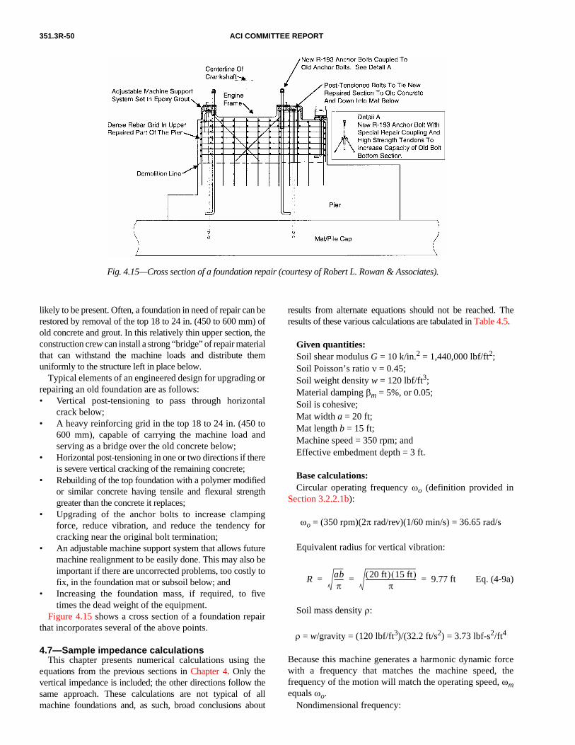
351.3R-50 ACI COMMITTEE REPORT
Fig. 4.15—Cross section of a foundation repair (courtesy of Robert L. Rowan & Associates).
likely to be present. Often, a foundation in need of repair can berestored by removal of the top 18 to 24 in. (450 to 600 mm) ofold concrete and grout. In this relatively thin upper section, theconstruction crew can install a strong “bridge” of repair materialthat can withstand the machine loads and distribute themuniformly to the structure left in place below.
Typical elements of an engineered design for upgrading orrepairing an old foundation are as follows:• Vertical post-tensioning to pass through horizontal
crack below;• A heavy reinforcing grid in the top 18 to 24 in. (450 to
600 mm), capable of carrying the machine load andserving as a bridge over the old concrete below;
• Horizontal post-tensioning in one or two directions if thereis severe vertical cracking of the remaining concrete;
• Rebuilding of the top foundation with a polymer modifiedor similar concrete having tensile and flexural strengthgreater than the concrete it replaces;
• Upgrading of the anchor bolts to increase clampingforce, reduce vibration, and reduce the tendency forcracking near the original bolt termination;
• An adjustable machine support system that allows futuremachine realignment to be easily done. This may also beimportant if there are uncorrected problems, too costly tofix, in the foundation mat or subsoil below; and
• Increasing the foundation mass, if required, to fivetimes the dead weight of the equipment.
Figure 4.15 shows a cross section of a foundation repairthat incorporates several of the above points.
4.7—Sample impedance calculationsThis chapter presents numerical calculations using the
equations from the previous sections in Chapter 4. Only thevertical impedance is included; the other directions follow thesame approach. These calculations are not typical of allmachine foundations and, as such, broad conclusions about
results from alternate equations should not be reached. Theresults of these various calculations are tabulated in Table 4.5.
Given quantities:Soil shear modulus G = 10 k/in.2 = 1,440,000 lbf/ft2;Soil Poisson’s ratio ν = 0.45;Soil weight density w = 120 lbf/ft3;Material damping βm = 5%, or 0.05;Soil is cohesive;Mat width a = 20 ft;Mat length b = 15 ft;Machine speed = 350 rpm; andEffective embedment depth = 3 ft.
Base calculations:Circular operating frequency ωo (definition provided in
Section 3.2.2.1b):
ωo = (350 rpm)(2π rad/rev)(1/60 min/s) = 36.65 rad/s
Equivalent radius for vertical vibration:
Eq. (4-9a)
Soil mass density ρ:
ρ = w/gravity = (120 lbf/ft3)/(32.2 ft/s2) = 3.73 lbf-s2/ft4
Because this machine generates a harmonic dynamic forcewith a frequency that matches the machine speed, thefrequency of the motion will match the operating speed, ωmequals ωo.
Nondimensional frequency:
R abπ
------ 20 ft( ) 15 ft( )π
-------------------------------- 9.77 ft= = =

FOUNDATIONS FOR DYNAMIC EQUIPMENT 351.3R-51
Eq. (4-11)
Method 1: Base vertical impedance—Veletsos: Eq. (4-15)From Table 4.1:(Values for 0.45 are interpolated between 0.33 and 0.5.)ν = 0.33 ν = 0.5 ν = 0.45γ1 = 0.350 0.000 0.103γ2 = 0.800 0.000 0.235γ3 = 0.000 0.170 0.120γ4 = 0.750 0.850 0.821
Parameter χv
Eq. (4-15c)
Parameter ψv
Eq. (4-15c)
Vertical impedance
Eq. (4-15c)
The stiffness is equivalent to the real part of kv*
kv = 98,100,000 lbf/ft or 8,170 k/in. Eq. (4-10)
The damping constant is derived from the imaginary partof kv
*
cv = (48,400,000 lbf/ft)/(36.65 rad/s) = Eq. (4-10)
ao Rωm ρ G⁄=
ao (9.77 ft)(36.65 rad/s) 3.73 lbf-s2 ft4⁄( )
(1,440,000 lbf/ft2 )-------------------------------------------- 0 . 5 7 6= =
χvγ1 γ2ao( )2
1 γ2ao( )+ 2---------------------------= =
0.103( ) 0.235( ) 0.576( )[ ]2
1 0.235( ) 0.576( )[ ]2+-------------------------------------------------------------- 0 . 0 0 1 8 5=
ψvγ1γ2 γ2ao( )2
1 γ2ao( )+ 2---------------------------= =
0.103( ) 0.235( ) 0.235( ) 0.576( )[ ]2
1 0.235( ) 0.576( )[ ]2+--------------------------------------------------------------------------------- 0 . 0 0 0 4 3 6=
kv∗ 4GR
1 ν–( )---------------- 1 χv– γ3ao
2–( ) iao γ4 ψv+( )+[ ]=
kv∗
4 1,440,000 lbf/ft2
( ) 9.77 ft( )
1 0.45–( )---------------------------------------------------------------------=
1 0.00185– 0.12( ) 0.576( )2–( ) i 0.576( ) 0.821 0.000436+( )+[ ]
kv ∗ 102,318,545 0.9583 i0.4731+[ ] 98,100,000 + i48,400,000 lbf/ft= =
1,321,000 lbf-s/ft, or 110.1 k-s/in.
Including material damping through Eq. (4-23) yieldsadjusted stiffness and damping terms ofkv(adj) = kv –2β ⋅ cv ⋅ ωmkv = 98,100 – 2(0.05)(1,321,000)(36.65) = 93,300,000 lb/ft =7770 k/in.cv(adj) = cv + 2β × kv/ωmcv = 1,321,000 + 2(0.05)(98,100,000)/(36.65) = 1,589,000lbf –s2/ft = 132.4 k – s2/in.
Method 2: Base vertical impedance—Veletsos approxi-mated: Eq. (4-16)/Table 4.2
Use the same input data as before. Use of Table 4.2 isallowed because ao is less than 2.0. From Table 4.2, usingcohesive soil, Cv1 = 7.5, Cv2 = 6.8
Vertical impedance
kv* = GR(Cv1 + i aoCv2) = (1,440,000 lbf/ft2) Eq. (4-16c)
(9.77 ft)[7.5 + i (0.576) (6.8)]
kv* = 105,500,000 + i 55,100,000 lbf/ft
The stiffness is equivalent to the real part of kv*
kv = 105,500,000 lbf/ft or 8790 k/in. Eq. (4-10)
The damping constant is derived from the imaginary partof kv
*
cv = 55,100,000/36.65 = 1,503,000 lbf-s/ft Eq. (4-10)
or 125.3 k-s/in.
Calculations using polynomial expansions of Cv1 and Cv2support the tabulated constants for this speed of operation
Table 4.5—Summary of vertical impedance calculations
Calculation basis kv, k/in. cv, k-s/in.* Comment
Noembedment
Eq. (4-15c) 8170 110.1 No material damping
adjust by 4.23 7770 132.4 5% material damping
Eq. (4-16c), Table 4.2 8790 125.3 No material damping
adjust by 4.23 8330 149.3 5% material damping
Eq. (14-3a), (4-12a) 8530 114.0 No material damping
adjust byadding 5% for
material damping
8530 120.4 5% material dampingΣWt = 187.5 k
Veletsos and Verbic (1973)
complete8030 133.5 5% material damping
incl.; “best” calc.
Embedment effects (addi-tive to above)
Eq. (4-21b) 972 37.9 No material damping
adjust by 4.23 833 40.6 5% side material damping
*Note: cv values have not been reduced as discussed in Section 4.2.

351.3R-52 ACI COMMITTEE REPORT
(ao = 0.576). For higher speeds, the difference between theconstant value and the polynomial are significant.
Including material damping through Eq. (4-23) yieldsadjusted stiffness and damping terms of:
kv = 8790 – 2(0.05)(125.3)(36.65) = 8330 k/in.cv = 125.3 + 2(0.05)(8790)/(36.65) = 149.3 k-s2/in.
Method 3: Base vertical impedance—Richart-Whitman: Eq. (4-12) and (4-13)
This approach is valid for ao less than 1.0. Assume themachine weighs 30 kips and the mat is 3.5 ft thick. Theseassumptions are not significant for the impedance in thevertical direction; the kv and cv values are not dependent onthese weights. For rotational motions there is some minordependence on the specific assumed values.
The base stiffness is calculated as
kv = 4GRo/(1 – ν) = 4(1,440,000 lbf/ft2) (4-13a)
(9.77 ft)/(1 – 0.45) = 102,300,000 lbf/ft or 8530 k/in.
The total weight of machine and foundation is
W = (20 ft)(15 ft)(3.5 ft)(0.15 kcf) + (30 kips) = 187.5 kips
Either weights (W, w) or masses (m, ρ) can be used inEq. (4-12) provided consistency is maintained. The massratio for this calculation is
Bv = (1 – ν)W/[4wRo3] Eq. (4-12a)
= (1 – 0.45)(187.5 kips)/[4(0.12 kcf)(9.77 ft)3]
= 0.230
Damping ratio (geometric damping)
Eq. (4-12a)
The total system mass is
Eq. (4-12a)
The damping constant is calculated as
Eq. (4-14)
To include the material damping as a simple addition, the5% material damping is added to the Dv value, and Eq. (4-14)is applied. The stiffness is not altered in this approach.
Dv0.425
Bv
------------- 0.425
0.23-------------- 0.886 88.6%= = = =
M Wg----- 187.5 kips
386.4 in./s2--------------------------- 0.485 k-s2/in.= = =
cv 2Dv kvM( ) 2 0.886( )= =
8530 k/in.( ) 0.485 k-s2/in.( ) 114.0 k-s2/in.=
Method 4: Base vertical impedance—Veletsos andVerbic (1973)
Veletsos and Verbic (1973) presents more completeversions of Eq. (4-15) that include material damping. Shortof a complete complex domain solution, this approach isaccepted as the best calculation basis. With materialdamping of 5%, those equations yield:
kv = 8030 k/in.cv = 133.5 k-s/in.
Embedment vertical impedance—Eq. (4-21)Because the dimensionless frequency (ao = 0.576) is in the
range of 0.5 to 1.5, the use of Table 4.2 factors is permissible.From Table 4.2, Sv1 = 2.7, Sv2 = 6.7
Embedment vertical impedance
kev* = Gsl [Sv1 + iaoSv2] (Eq. (4-21b)
= (1,440,000 lbf/ft2)(3 ft)[(2.7 + i (0.576)(6.7)]
= 11,660,000 + i16,670,000 lbf/ft
The stiffness is equivalent to the real part of kev*
kv = 11,660,000 lbf/ft, or 972 k/in. Eq. (4-10)
The damping constant is derived from the imaginary partof kev
*
cv = (16,670,000 lbf/ft)/(36.65 rad/s) (4-10)
= 455,000 lbf-s/ft, or 37.9 k-s/in.
These values can be adjusted for the material dampingeffects of the embedment material. The material damping ofthis side material may be different from the base material.Using Eq. (4-23) yields adjusted stiffness and damping terms of
kv = (972 k/in.) – 2 (0.05)(37.9 k-s/in.)(36.65 rad/s)
= (972 k/in.) – (139.0 k/in.) = 833 k/in.
cv = (37.9 k-s/in.) + 2 (0.05)(972 k/in.)/(36.65 rad/s)
= (37.9 k-s/in.) + (2.7 k-s/in.) = 40.6 k-s/in.
The embedment impedance values are directly additive tothe base impedance values. For example, combining with theresults from the complete solution of Veletsos yields
(kv)total = (kv)base + (kv)embed
= (8030 k/in.) + (833 k/in.) = 8860 k/in.
cv 2Dv kvM( ) 2 0.936( )= =
8530 k/in.( ) 0.485 k-s2/in.( ) 120.4 k-s2/in.=

FOUNDATIONS FOR DYNAMIC EQUIPMENT 351.3R-53
(cv)total = (cv)base + (cv)embed
= (133.5 k-s/in.) + (40.6 k-s/in.) = 174.1 k-s/in.
Base impedance values from other calculations could alsobe used. Most often, consistent approaches are used. Theoverall results of these various calculations are tabulated inTable 4.5.
Calculation of displacementsOnce the stiffness and damping have been determined, the
engineer calculates the maximum response using the approachin Section 4.3. For demonstration, use the Veletsos and Verbicvalues with the embedment terms added and reduce thedamping by 50% as a rough consideration of possible soillayering effects. Thus, the embedded stiffness is 8860 k/in.,and the embedded damping is 87 k-s/in. The total systemweight is 187.5 kips. (Refer to Method 3 calculation.)
To calculate motions, determining an excitation force is neces-sary. Use a given rotor weight of 10 kips and Eq. (3-7) to get
F = 10,000 lbf ⋅ 350 rpm/6000 = 583 lbf Eq. (3-7)
Applying Eq. (4-44) requires calculating ωn and β.
ωn = (k /m)1/2 = (kg/W) 1/2
ωn = (8860 k/in. ⋅ 32.2 ft/s2 ⋅ 12 in./ft/187.5 k)1/2 = 135.1 rad/s
Eq. (4-44)
The predicted amplitude motion of this SDOF system is0.0662 mils or 0.0000662 in. (0.00168 mm). The peak-to-peak motion is 0.1324 mils (3.36 mm) at 350 rpm. Forcomparison using Fig. 3.10, this motion at this speed is seento qualify as “extremely smooth.” Similarly on Fig. 3.11, theresultant motion at the operating speed is well below thevarious corporate and other standards for acceptance.
β c
2 km-------------- c
2 kWg-----
---------------= =
β 87 k-s/in.
2 8860 k/in. 187.5 k
32.2 ft/s2 12 in./ft⋅---------------------------------------------
------------------------------------------------------------------------------ 0.663= =
A F k⁄
1 ωo ωn⁄( )2–( )2
2βωo ωn⁄( )2+
---------------------------------------------------------------------------------=
A 583 8860⁄
1 36.65 135.1⁄( )2–( )
22 0.663( ) 36.65( ) 135.1( )⁄( )
2+--------------------------------------------------------------------------------------------------------------------------------------=
0.0658 mils0.994
----------------------------=
Although a ωn value is computed for use in Eq. (4-44), thisis not actually the system natural frequency because the valuehas been computed using a stiffness value specific to motion ata specific frequency (350 rpm or 36.65 rad/s). With frequencydependent impedance, as the frequency of excitation increases,the stiffness decreases. Determining the frequency at whichmaximum response occurs requires an iterative solution acrossa range of frequencies. For this problem, such an iterationshows that the maximum undamped response (comparablewith the aforementioned ωn value) occurs at a speed of1030 rpm (108 rad/s) and the more realistic, maximumdamped response occurs at 1390 rpm (146 rad/s).
CHAPTER 5—CONSTRUCTION CONSIDERATIONS5.1—Subsurface preparation and improvement
5.1.1 General considerations—Equipment foundationscan be supported on soil, rock, piles, or drilled piers,depending on the geotechnical conditions of the site. Theengineer and geotechnical consultant determine the extent ofsoil investigation and subsurface preparation, which mayvary from minimal to extensive. The construction contractorexecutes the subsurface preparation and the geotechnicalengineer verifies it. Adjustments are generally made asrequired as work progresses.
The engineer should consider the effect of vibratory andimpulsive loading on the underlying soils to determine ifthey are susceptible to dynamic consolidation, particularlyunder foundations of large dynamic equipment. Thus, addi-tional soil parameters, such as shear wave velocity, dynamicmodulus of elasticity, and Poisson’s ratio, may be requiredfrom the soil investigation to perform a dynamic analysis(Chapter 3).
5.1.2 Specific subsurface preparation and improve-ments—The contractor should prepare the site in a wayconsistent with the assumptions made and parameters usedin the foundation analysis. Due to the dynamic nature ofloads acting on the foundations, the contractor should payparticular attention to proper compaction and consolidationof the soils.
Specific subsurface preparation and related treatment maybe required for one or more of the following reasons:• If the exploratory borings, field tests and observations,
and subsequent laboratory tests dictate the necessity ofa subsurface treatment;
• If the exploratory borings reveal nonuniform and heter-ogeneous conditions with irregularities requiring localremedies; and
• If close inspection of the foundation excavation indicatesconditions other than the ones extrapolated from theborings, thereby requiring special preparation andtreatment—generally of a localized nature.
Common site-specific subsurface preparations and treat-ment for these conditions are:
a) Unstable excavation slopes—Unstable slopes may bestabilized by flattening the slope, benching, dewatering,shoring, freezing, injection with chemical grouts, orsupporting with dense slurries;
351.3R-54 ACI COMMITTEE REPORT
b) Stratification—Excavations with slopes parallel to thedirection of stratification are avoided by flattening the slopeor by providing adequate shoring;
c) Wet excavation—During construction, groundwater isnormally lowered below the bottom level of the excavation;deep well pumps or well points are commonly used. Anothermethod is to create an impervious barrier around the excavationwith cofferdams or caissons, chemical grout injection, sheetpiles, or slurry trenches. A sump pit collects groundwaterintrusion. The selection of an appropriate method dependson the characteristics of the surface soils encountered, costs,and the preferences of the constructor;
d) Small surface pockets of loose sand—Loose sandpockets are normally compacted to the degree of specifiedcompaction. Alternatively, if the predominant soil is hard,the loose sand may be removed and replaced with flowablefill. Loose sand under dynamically loaded foundations isparticularly prone to differential settlement and should beeliminated during construction;
e) Large deposits of loose sands—The loose sands may bestabilized by vibrofloatation or dynamic consolidation,whichever offers an economic advantage. A prediction oflong-term settlements considering the vibratory loads maybe necessary;
f) Presence of organic material or unconsolidated softclays—All organic materials and soft clays are normallyremoved and replaced with suitable, well-compacted fill thatprovides the characteristics desired for the proper perfor-mance of the foundation. Alternatively, piling or drilled piersmay be used to carry foundation loads to sound bearing strata;
g) Fissured rock—The extent of fissures is evaluated todetermine if remedial treatment is needed. Pressure groutingis a suitable remedy for some types of fissures. In the case ofseismic faults, thorough geotechnical and geological evalua-tion is required to ascertain the potential hazard. Wheresignificant hazards exist, relocation of the entire facility toavoid the hazard is a suitable remedy;
h) Irregularly weathered rock—The weathered seams arecleaned and replaced with lean concrete. Alternatively, thefoundation may be revised to reach sound rock;
i) Solution cavities in limestone deposits—The voids, ifsmall, are pumped full of grout or, in the case of large holes,lean concrete under a pressure head;
j) Unconsolidated clay—Clays may be preloaded andrelated settlements monitored. (Early identification is impor-tant to gain lead time and avoid slippage in the constructionschedule.) Alternatively, piling or drilled piers may be usedto carry foundation loads to firm bearing strata; and
k) Cold climates—The construction crew should not placefoundations on fine-grained soils subject to frost heave. Thecrew should provide proper drainage by placing a free-draining sand or gravel layer under the foundation to miti-gate the possibility of frost heave where such hazard exists.As an alternative, the bottom of the foundation is placedbelow the frost line.
5.2—Foundation placement tolerancesFoundation placement tolerances depend largely on the
type of equipment being supported and are specified by theengineer on the drawings or in the specifications. Theconstruction crew should use templates during concreteplacement to support anchor bolts and other embedmentsthat must be precisely positioned.
5.3—Forms and shores5.3.1 General requirements for forms—Forms and shoring
for construction of concrete foundations should follow therecommendations of ACI 347R. As applicable, provisions ofACI 301 should be specified.
5.3.2 Shoring—Shoring should support the concrete loads,impact loads, and temporary construction loads. Transverse andlongitudinal bracing may be required to sustain lateral forces.
The formwork engineer should consider wind loads in theshoring design. It is not usually necessary to considerseismic loads due to the limited time shoring is in place. Alicensed professional engineer should prepare the design ofthe formwork and submit it to the design engineer for review.
5.3.3 Shoring systems and formwork for large elevatedfoundations—For large equipment foundation pedestals,such as turbine-generator foundations, temporary formworksystems are generally used. Less frequently, permanentsystems may be used for special applications. The contractorusually selects a temporary support system. The selection isinfluenced by the erection sequence of the building (if theequipment is enclosed), the equipment installation proce-dure, and access requirements at the time of placement of thefoundation. Some of the permanent systems may affect thedesign and cost of the foundation. Therefore, the designengineer may wish to consult with building contractorsbefore deciding on a permanent formwork system.
Some of the systems used are:• Standard construction shoring consisting of temporary
shore legs supported by the foundation mat and supportingthe soffit forms of a foundation deck;
• Shoring consisting of structural steel beams supportedon brackets attached to the foundation columns. Theforms rest on top of the beams. Jacking devices areused to lower the beams and forms for removal after theconcrete reaches sufficient strength;
• Embedded structural steel shapes (rolled wide flangebeams, girders, angles, or channels) supported on thefoundation columns and carrying the permanent deckforms. The forms (steel decking) usually rest on thebottom flanges of the steel shapes. Because the steelshapes are embedded in the foundation deck, the designengineer should to be careful to avoid interferenceswith the reinforcing bars and with other embedments(anchor bolts, plates, pipe sleeves and conduits);
• Embedded structural steel trusses supported on thefoundation columns and carrying the permanent deckforms on the bottom chords. The trusses, if speciallydesigned, can also be considered as reinforcing to carrythe operating loads acting on the foundation deck.Checking for interferences between the trusses and the

FOUNDATIONS FOR DYNAMIC EQUIPMENT 351.3R-55
reinforcing bars and other embedments is important toavoid serious construction problems; and
• Precast concrete deck forms supported by the foundationcolumns. These can be flat bottom “U” and double “U”shapes.
All of these systems, except the Standard ConstructionShoring System, allow early access under the foundationdeck. The standard shoring system, however, has the leastimpact on the foundation design. The remaining foursystems should be coordinated, in varying degrees, with thefoundation design.
In all five cases, the design engineer should review thecontractor’s construction procedure.
5.4—Sequence of construction andconstruction joints
Many large machine foundations are too massive for theconcrete to be placed in one continuous operation. Constructionjoints subdivide large foundations into smaller placementunits. Subdivision of large foundations by construction jointsalso helps reduce internal heat of hydration in concrete andshrinkage cracks in the foundation. To gain maximumbenefit, the constructor should place alternate foundationsegments and allow them cure and shrink as long as theconstruction schedule permits before the interveningsegments are placed.
The structural integrity of the foundation requires thatjoints be carefully constructed using accepted practices forconstruction joints in major concrete structures, such asspecified in ACI 301. Project specifications normally requirethat the constructor obtain the approval of the engineer forconstruction joint locations and details.
The location of construction joints should follow normalreinforced concrete building practice. Joints in columns shouldbe located at or near the floor line and at the underside forsupported beams. If the beams are haunched, the joints shouldbe located at the underside of the deepest haunch. Joints inbeams and mats should be located at sections of low stress.
Transverse construction joints should be at right angles tothe main reinforcement. Horizontal joints in beams and slabsplaced in more than one lift should be supplied with sufficienttransverse reinforcing to develop the required horizontal shearcapacity by shear friction. Preparation of construction jointsshould be in accordance with ACI 304R.
Transfer of loads across a construction joint should beprovided for by specific means. Tensile loads, for example,should be transferred by extending reinforcing bars across thejoint. Transfer of compressive loads can be accomplished byensuring that the concrete on both sides of the joint is strongand dense. Additional measures are needed to transfer shearloads. Shear keys should be cast in the face of the joint. Alter-natively, the face of the joint can be roughened sufficiently forshear loads to be transferred by shear friction. With the lattermethod, sufficient reinforcing bars should extend across thejoint to hold the surfaces of the joint in close contact.
5.5—Equipment installation and setting5.5.1—Shims, wedges, and bolts represent a typical interface
system between the foundation and the machine base. Thechosen interface system can be influenced by the machinemanufacturer’s recommendations and requirements, thefoundation construction procedures, the setting and adjustmentof the equipment, and the final tolerances.
Shims, which are usually carbon steel or brass stock in variousthicknesses, have both economical and high load-bearingqualities. Shims should be fabricated with rounded corners.
Wedges are usually the double-wedge type and are offeredby several mounting-equipment manufacturers. The doublewedge mount often has one or more threaded studs forprecise vertical adjustment and for locking the sliding wedgeinto the required position. A lock nut may also be used forlocking the main horizontal stud into the final position.
Other types of wedges often used by millwrights includevarious shaped temporary steel wedges. Temporary wedgesare usually tolerance adjustment tools placed beforegrouting, and they are removed after the hardening of thegrout material. Permanent wedge assemblies allow futureadjustments on ungrouted equipment bases.
The manufacturer’s drawings should give the required boltdiameters. For construction, the design drawings or specifi-cations should provide bolt diameters, types, overall lengths,threaded lengths, projections, materials, the method of bolttightening, and required torques. When a specific preload isrequired by the manufacturer or design engineer, Eq. (5-1)can be used to determine the bolt torque
Tb = WpKndn (5-1)
whereTb = bolt torque, lbf-in. (N-m);dn = nominal bolt diameter, in.;Wp = preload, lbf (Section 4.5.2); andKn = nut factor for bolt torque (dimensionless).
Typical values of Kn (often in the range of 0.1 to 0.3) aretabulated in Bickford (1995) and vary with the lubricationand condition of the bolts. Special coatings may requiremanufacturer’s data.
Required bolt tightening can be accomplished with a post-tensioning jacking procedure, a turn-of-the-nut method, or acalibrated wrench. Post-tensioning jacking is used on thedeeper anchorages with nonbonded shanks. When the shanklength is embedded in concrete, the turn-of-the-nut methodor sequential calibrated wrench tightening is specified.Section 4.4.2.4 presents comments on monitoring the bolttension. Impact wrenches are not used for tightening a boltcomponent when part of the anchorage is embedded inconcrete because of the extremely high torque and tensileforces delivered by such tools.
5.5.2—Embedments in the concrete include the anchorbolt assemblies previously described, shear lugs, and sheartransferring devices. Because shear is a component of a totalload transferred to the concrete foundation, steel lugs can beintegral parts of the machine base. Such lugs are grouted intoshear key grooves previously cast into the concrete base.

351.3R-56 ACI COMMITTEE REPORT
5.6—Grouting5.6.1 Types of grout—There are two basic types of grout:
cementitious (cement-based) grouts and polymer (includingepoxy-based) grouts. Cementitious grouts are lower in cost,but polymer grouts have higher resistance to chemicals,shock, and vibratory loads.
5.6.2 Applications—ACI 351.1R contains details on theapplication of grouts. In specifying grout systems, the engi-neer should consider the different characteristics of eachtype of grout along with field limitations and match thesewith specific requirements of the job. In evaluating whichcementitious grout should be used, the engineer shouldconsider the placability of the grout and its physical properties:volume change, compressive strength, working time, consis-tency, and setting time. In evaluating polymer grouts, theengineer should consider the same factors along with creepand the effects of temperature-induced volume changes. Theengineer should review the design of the equipment base,accessibility of the grouting location, clearances providedfor the grout, and design of anchor bolts. Most of the groutson the market are premixed, prepackaged materials and containmanufacturer’s instructions on surface preparation, form-work, mixing, placing, and curing procedures.
5.7—Concrete materials (ACI 211.1, ACI 301)Large machine foundations require special attention to the
design and control of the concrete mixture (ACI 207.1R andACI 207.4R).
Many foundations are massive enough for the heat ofhydration of the cement to generate a large thermal differentialbetween the inside and the outside, which may causeunacceptable surface cracking unless steps are taken toreduce the rate of release of this heat. Creep, differentialthermal expansion, and shrinkage can cause distortion of thefoundation and result in unacceptable changes in machinealignment. It is important to design the concrete mixture tominimize creep and shrinkage and to reduce the thermalexpansion of the hardened concrete. Temperatures may bemonitored using thermocouples or resistance thermometers.If excessive temperatures are detected, surface coolingsystems can be used to provide limited benefits in controllingtemperatures (ACI 207.4R). Expansive reaction of theconcrete aggregate with alkalies in the cement can beavoided by proper choice of cement and aggregate.
To minimize the rate of release of the heat of hydration,and to control shrinkage and creep, the following steps arenormally followed:• The lowest content of cementitious material consistent
with attaining the required strength and durability is used;• Part of the cement is replaced with fly ash or other
pozzolan;• The placing temperature of fresh concrete is lowered by
chilling the aggregate, using chipped ice for mixingwater, or both;
• The largest practical size aggregate is used to allow furtherreduction in the amount of cement;
• Moderate heat cement (Type II) is used;• A water-reducing agent is used to allow further reduction
of the cement factor;• Low slump and effective vibration are used;• Concrete placement by pumps, which require concrete
mixtures having high amounts of cement and smallaggregate sizes, is avoided; and
• Sizes of placements for large foundations are reduced.High-range water-reducing admixtures may be an appro-
priate choice because they are consistent with their generalapplicability to mass concrete applications and heavilyreinforced installations for which workability is an issue.
The coefficient of thermal expansion of the hardenedconcrete can be controlled by the choice because they are ofaggregates and because it primarily depends on the coefficientof thermal expansion of the aggregate. When excessive thermalexpansion may be a problem, the coefficient of expansion ofavailable aggregates is measured to determine their suitabilityfor the application. (In many regions there may be very limitedchoices in the types and sources of aggregates.)
Expansion of concrete from alkali-aggregate reaction canbe minimized by using a low-alkali cement, by replacing aportion of the cement with a fly ash or nonfly ash pozzolanmeeting the requirements of ASTM C 618, and by selectinglow-reactivity aggregates. The potential reactivity ofaggregates can be evaluated with the procedures and testsdescribed in ASTM C 295, ASTM C 227, ASTM C 289, andASTM C 586. ASTM C 33 and ACI 225R cover the evaluationmethods of the potential reactivity of aggregates.
The cement content should be low enough to help meetheat of hydration requirements but high enough to meetstrength, creep, and shrinkage requirements. (It may not bepossible to completely solve the heat problem by reducingthe heat of hydration. Cooling, small placements, orpozzolans may also be needed.)
5.8—Quality controlBecause the foundation for the machine acts as an integral
part of the machine-foundation-soil system, an appropriatequality control program should be implemented to ensurethat the design requirements are met during construction.ACI 311.4R contains guidance on items to include in thequality program. ACI 311.5R contains guidance on concreteplant inspection and testing of ready-mixed concrete. ACI SP-2contains general guidance on inspection of concrete. Thequality control program should include requirements forcontrol of material quality, the engineer’s approval of criticalconstruction procedures, and onsite verification of compli-ance with design drawings and project specifications by aqualified field engineer, preferably certified by ACI as aconcrete construction inspector.
Design drawings and project specifications should providefoundation requirements to the constructor and field engineer.The field engineer typically is required to report to the designengineer or owner any changes or modifications to the spec-ified design warranted by the conditions in the field. Thedesign engineer or owner should approve any changes in thespecified design and document them in accordance withpreestablished procedures.

FOUNDATIONS FOR DYNAMIC EQUIPMENT 351.3R-57
The quality control program and inspections should be thor-oughly documented and be available for the owner’s reviews.The quality control program should be consistent with thosecommonly implemented for construction projects of similarimportance. ACI 301 can be cited as part of that quality controlprogram. Laboratories providing testing and inspections shouldbe accredited to the requirements of ASTM E 329.
CHAPTER 6—REFERENCES6.1—Referenced standards and reports
Documents and standards produced by national and inter-national organizations that are relevant and referenced in thisreport are listed as follows. In the preparation of this report,currently available editions of these documents were used.Because these documents are subject to frequent revision,the reader is advised to contact the sponsoring agency for thelatest versions.
Acoustical Society of America (ASA)ASA/ Mechanical Vibration—Balance Quality ANSI S2.19 Requirements of Rigid Rotors, Part 1:
Determination of Permissible ResidualUnbalance
American Concrete Institute (ACI)ACI 117 Standard Specification for Tolerances for
Concrete Construction and MaterialsACI 116R Cement and Concrete TerminologyACI 121R Quality Management System for Concrete
ConstructionACI 207.1R Mass ConcreteACI 207.2R Cracking of Massive ConcreteACI 207.4R Cooling and Insulating Systems for Mass
ConcreteACI 211.1 Standard Practice for Selecting Proportions
for Normal, Heavyweight, and MassConcrete
ACI 215R Considerations for Design of ConcreteStructures Subjected to Fatigue Loading
ACI 225R Guide to the Selection and Use of HydraulicCements
ACI 301 Specifications for Structural ConcreteACI 304R Guide for Measuring, Mixing, Trans-
porting, and Placing ConcreteACI 307/307R Design and Construction of Reinforced
Concrete Chimneys and CommentaryACI 311.4R Guide for Concrete InspectionACI 311.5R Guide for Concrete Plant Inspection and
Field Testing of Ready-Mixed ConcreteACI 318/318R Building Code Requirements for Structural
Concrete and CommentaryACI 347R Guide to Formwork for ConcreteACI 349.1R Reinforced Concrete Design for Thermal
Effects on Nuclear Power Plant StructuresACI 351.1R Grouting Between Foundations and Bases
for Support of Equipment and MachineryACI 351.2R Foundations for Static EquipmentACI SP-2 ACI Manual of Concrete Inspection
American Petroleum Institute (API)API 541 Form-Wound Squirrel Cage Induction
Motors—250 Horsepower & LargerAPI 610 Centrifugal Pumps for Petroleum, Heavy
Duty Chemical, & Gas Industry ServicesAPI 612 Special-Purpose Steam Turbines for Petro-
leum, Chemical, & Gas Industry ServicesAPI 613 Special-Purpose Gear Units for Petroleum,
Chemical, & Gas Industry ServicesAPI 617 Centrifugal Compressors for Petroleum,
Chemical, and Gas Industry ServicesAPI 618 Reciprocating Compressors for Petroleum,
Chemical, and Gas Industry ServicesAPI 619 Rotary-Type Positive Displacement
Compressors for General Refinery ServicesAPI 684 Tutorial on the API Standard Paragraphs
Covering Rotor Dynamics and Balance (AnIntroduction to Lateral Critical and TrainTorsional Analysis and Rotor Balancing)
API 686 Recommended Practice for MachineryInstallation and Installation Design
American Society of Civil Engineers (ASCE)ASCE 7 Minimum Design Loads for Buildings and
Other Structures
ASTM InternationalASTM A 36/ Standard Specification for Carbon StructuralA 36M SteelASTM A 193 Standard Specification for Alloy-Steel and
Stainless Steel Bolting Materials for High-Temperature Service
ASTM A 307 Standard Specification for Carbon SteelBolts and Studs, 60,000 PSI TensileStrength
ASTM A 615 Standard Specification for Deformed andPlain Billet-Steel Bars for Concrete Rein-forcement
ASTM C 33 Standard Specification for ConcreteAggregates
ASTM C 227 Standard Test Method for Potential AlkaliReactivity of Cement-Aggregate Combina-tions (Mortar-Bar Method)
ASTM C 289 Standard Test Method for Potential Alkali-Silica Reactivity of Aggregates (ChemicalMethod)
ASTM C 295 Standard Guide for Petrographic Examinationof Aggregates for Concrete
ASTM C 580 Standard Test Method for Flexural Strengthand Modulus of Elasticity of Chemical-Resistant Mortars, Grouts, MonolithicSurfacings, and Polymer Concretes
ASTM C 586 Standard Test Method for Potential AlkaliReactivity of Carbonate Rocks for ConcreteAggregates (Rock Cylinder Method)
ASTM C 618 Standard Specification for Coal Fly Ashand Raw or Calcined Natural Pozzolan forUse as a Mineral Admixture in Concrete
351.3R-58 ACI COMMITTEE REPORT
ASTM C 1181 Standard Test Methods for CompressiveCreep of Chemical-Resistant PolymerMachinery Grouts
ASTM D 4015 Standard Test Methods for Modulus andDamping of Soils by the Resonant ColumnMethod
ASTM E 329 Standard Specification for AgenciesEngaged in the Testing and/or Inspection ofMaterials Used in Construction
ASTM F 1554 Standard Specification for Anchor Bolts,Steel, 36, 55, and 105-ksi Yield Strength
ASTM SI10 American National Standard for Use of theInternational System of Units (SI): TheModern Metric System
Deutsches Institut für Normung (DIN)DIN 4024 Part 1 Machine Foundations: Elastic
Supporting Constructions for Machineswith Rotating Masses
DIN 4024 Part 2 Machine Foundations: Rigid SupportingConstructions for Machines with PeriodicExcitation
DIN 4025 Foundations for Drop Forging MachineryDIN 4150 Part 1 Vibrations in Buildings: Prediction of
Vibration ParametersDIN 4150 Part 2 Vibrations in Buildings: Effects on
Persons in BuildingsDIN 4150 Part 3 Vibrations in Buildings: Effects on
Structures
Federal Emergency Management Administration (FEMA)FEMA 302 NEHRP Recommended Provisions for
Seismic Regulations for New Buildings andOther Structures, 1997
International Conference of Building Officials (ICBO)IBC International Building CodeUBC Uniform Building Code
International Standards Organization (ISO)ISO 1940-1 Mechanical Vibration—Balance Quality
Requirements of Rigid Rotors—Part 1:Determination of Permissible ResidualUnbalance
ISO 2631-1 Mechanical Vibration and Shock—Evalu-ation of Human Exposure to Whole BodyVibration—Part 1: General Requirements
ISO 10816-1 Mechanical Vibration—Evaluation ofMachine Vibration by Measurements on Non-Rotating Parts—Part 1: General Guidelines
ISO 10816-2 Mechanical Vibration—Evaluation ofMachine Vibration by Measurements onNon-Rotating Parts—Part 2: Large Land-Based Steam Turbine Generator Sets inExcess of 50 MW
ISO 10816-3 Mechanical Vibration—Evaluation ofMachine Vibration by Measurements onNon-Rotating Parts—Part 3: Industrial
Machines with Nominal Power Above 15 kWand Nominal Speeds Between 120 r/min and15,000 r/min when Measured In Situ
ISO 10816-4 Mechanical Vibration—Evaluation ofMachine Vibration by Measurements onNon-Rotating Parts—Part 4: Gas TurbineDriven Sets Excluding Aircraft Derivatives
ISO 10816-5 Mechanical Vibration—Evaluation ofMachine Vibration by Measurements onNon-Rotating Parts—Part 5: Machine Setsin Hydraulic Power Generating andPumping Plants
ISO 10816-6 Mechanical Vibration—Evaluation ofMachine Vibration by Measurements on Non-Rotating Parts—Part 6: ReciprocatingMachines with Power Ratings above 100 kW
Verein Deutscher Inginieure (VDI)VDI 2057 Effect of Mechanical Vibrations on Human
Beings
These publications may be obtained from these organizations:
Acoustical Society of America335 East 45th St.New York, NY 10017-3483web: http://asa.aip.org
American Concrete Institute38800 Country Club Dr.Farmington Hills, MI 48331Web: http://www.concrete.org
American Petroleum InstituteOrder Desk1220 L St. NWWashington, DC 20005-4070Web: http://www.api.org
American Society of Civil Engineers1801 Alexander Bell Dr.Reston, VA 20191Web: http://www.asce.org
ASTM International100 Barr Harbor Dr.West Conshohocken, PA 19428Web: http://www.astm.org
Deutsches Institut für Normung (DIN)Burggrafenstrasse 6DE-10772 BerlinGermanyWeb: http://www.din.de
Federal Emergency Management AgencyBuilding Seismic Safety Council1090 Vermont Avenue, Suite 700Washington, D.C. 20005Web: http://www.bssconline.org

FOUNDATIONS FOR DYNAMIC EQUIPMENT 351.3R-59
International Conference of Building Officials5360 Workman Mill RoadWhittier, CA 90601-2298Web: http://www.icbo.org
International Standards Organization1, rue de VarembéCase postale 56CH-1211 Genéve 20SwitzerlandWeb: http://www.iso.ch
Verein Deutscher Inginieure (VDI)P.O. Box 10 11 39D-40002 DusseldorfGermanyWeb: http://www.vdi.de
6.2—Cited referencesArya, S. C.; O’Neill, M. W.; and Pincus, G., 1979, Design
of Structures and Foundations for Vibrating Machines, GulfPublishing Co., Houston, Tex.
Baxter, R. L., and Bernhard, D. L., 1967, “Vibration Toler-ances for Industry,” ASME Paper 67-PEM-14, Plant Engi-neering and Maintenance Conference, Detroit, Mich., Apr.
Beredugo, Y. O., and Novak, M., 1972, “Coupled Horizontaland Rocking Vibration of Embedded Footings,” CanadianGeotechnical Journal, NRCC, V. 9, No. 4, pp. 477-497.
Bickford, J. H., 1995, An Introduction to the Design andBehavior of Bolted Joints, New York and Basel, MarcelDekker, Inc., 3rd Edition, 992 pp.
Blake, M. P., 1964, “New Vibration Standards for Mainte-nance,” Hydrocarbon Processing and Petroleum Refiner, GulfPublishing Co, Houston, Tex., V. 43, No. 1, Jan., pp. 111-114.
Bowles, J. E., 1996, Foundation Analysis and Design, 5thEdition, McGraw-Hill, New York, 1024 pp.
Das, B. M., 1993, Principles of Soil Dynamics, Boston,Mass., PWS-Kent Publishers, 592 pp.
Elsabee, F., and Morray, J. P., 1977, “Dynamic Behaviorof Embedded Foundations,” Research Report R77-33, CivilEngineering Department, Massachusetts Institute of Tech-nology, Cambridge, Mass.
EPRI, 1980 “Dynamics of Power Plant Fan-FoundationSystems,” Final Report CS-1440, July, p. 3-12.
Fang, H.-Y., 1991, Foundation Engineering Handbook,2nd Edition, Van Nostrand Reinhold, New York, 924 pp.
Gazetas, G., 1983, “Analysis of Machine FoundationVibrations: State of the Art,” Soil Dynamics and EarthquakeEngineering, V. 2, No. 1, Jan., pp. 2-42.
GERB, 1995, Vibration Isolation Systems, 9th Edition,GERB Vibration Control Systems, Inc., Lisle, Ill.
Hardin, B. O., and Black, W. L., 1968, “VibrationModulus of Normally Consolidated Clay,” Journal of SoilMechanics and Foundations, ASCE, V. 92, No. SM2, Mar.,pp. 353-369.
Hardin, B. O., and Richart, F. E., Jr., 1963, “Elastic WaveVelocities in Granular Soils,” Journal of Soil Mechanics andFoundations, ASCE, V. 89, No. SM1, Feb., pp. 33-65.
Harris, C. M., 1996, Shock and Vibration Handbook, 4thEdition, McGraw-Hill, New York, 1456 pp.
Karabalis, D. L., and Beskos, D. E., 1985, “DynamicResponse of 3-D Embedded Foundations by BoundaryElement Method,” 2nd Joint ASCE/ASME MechanicsConference, Albuquerque, N.M., 34 pp.
Kausel, E., and Ushijima, R., 1979, “Vertical andTorsional Stiffness of Cylindrical Footings,” ResearchReport R79-6, Civil Engineering Department, Massachu-setts Institute of Technology, Cambridge, Mass.
Kobayashi, S., and Nishimura, N., 1983, “Analysis ofDynamic Soil-Structure Interactions by Boundary IntegralEquation Method,” 3rd International Symposium on Numer-ical Methods in Engineering, Paris, pp. 342-353.
Kuhlmeyer, R. L., 1979a, “Vertical Vibration of Piles,”Journal of Geotechnical Engineering, ASCE, V. 105, No. GT2,Feb., pp. 273-287.
Kuhlmeyer, R. L., 1979b, “Static and Dynamic LaterallyLoaded Floating Piles,” Journal of Geotechnical Engi-neering, ASCE, V. 105, No. GT2, Feb., pp. 289-304.
Lakshmanan, N., and Minai, R., 1981, “Dynamic SoilReactions in Radially Non-homogeneous Soil Media,”Bulletin of the Disaster Prevention Research Institute, KyotoUniversity, Part 2, V. 31, No. 279, pp. 79-114.
Lifshits, A.; Simmons, H. R.; and Smalley, A. J., 1986,“More Comprehensive Vibration Limits for RotatingMachinery,” Journal of Engineering for Gas Turbines andPower, ASME , V. 108, No. 4, Oct., pp. 583-590.
Mandke, J. S., and Smalley, A. J., 1989, “FoundationThermoelastic Distortion,” Report No. 89-3, Pipeline andCompressor Research Council.
Mandke, J. S., and Smalley, A. J., 1992, “Thermal Distortionof Reciprocating Compressor Foundation Blocks,” ASMEPaper No. 92-Pet-3, ASME Energy-Sources TechnologyConference and Exhibition, Jan. 26-30, Houston, Tex.
Mandke, J. S., and Troxler, P. J., 1992, “Dynamics ofCompressor Skids,” GMRC Technical Report No. TR 92-2,Gas Machinery Research Council, Mar.
Mitwally, H., and Novak, M., 1987, “Response of OffshoreTowers with Pile Interaction,” Journal of EngineeringMechanics, ASCE, V. 113, No. 7, July, pp. 1065-1084
Novak, M., 1970, “Prediction of Footing Vibrations,”Journal of the Soil Mechanics and Foundations Division,ASCE, V. 96, No. SM3, May, pp. 837-861.
Novak, M., 1974, “Dynamic Stiffness and Damping ofPiles,” Canadian Geotechnical Journal, NRCC, V. 11, No. 4,pp. 574-598.
Novak, M., 1977, Soil-Pile-Foundation Interaction,Proceedings of the 9th International Conference on SoilMechanics and Foundation Engineering, Japanese Societyof Soil Mechanics and Found Engineering, Tokyo, Japan,July 11-15., pp. 309-315.
Novak, M., 1979, “Soil Pile Interaction Under DynamicLoads,” Numerical Methods in Offshore Piling: Proceedingsof a Conference Organized by the Institution of Civil Engineersand Held in London, May 22-23, ICE, London, pp. 59-68.
Novak, M., and Beredugo, Y.O., 1972, “Vertical Vibra-tion of Embedded Footings,” Journal of the Soil Mechanics

351.3R-60 ACI COMMITTEE REPORT
and Foundations Division, ASCE, V. 98, No. SM12, Dec.,pp. 1291-1310.
Novak, M., and Sachs, K., 1973, “Torsional and CoupledVibrations of Embedded Footings,” International Journal ofEarthquake Engineering and Structural Dynamics, V. 2, No. 1,pp. 11-33.
Novak, M., and Sheta, M., 1980, “Approximate Approachto Contact Problems of Piles,” Dynamic Response of PileFoundations, Analytical Aspects: Proceedings of a SessionSponsored by the Geotechnical Engineering Division at theASCE National Convention, Oct. 30, M. W. O’Neill and R.Dobry, eds., ASCE, New York.
Novak, M., and Sheta, M., 1982, “Dynamic Response ofPiles and Pile Groups,” Proceedings of the 2nd InternationalConference on Numerical Methods in Offshore Piling, Apr.29-30, University of Texas, Austin, Tex.
Pantermuehl, P. J., and Smalley, A. J., 1997a,“Compressor Anchor Bolt Design,” GMRC TechnicalReport No. TR 97-6, Gas Machinery Research Council, Dec.
Pantermuehl, P. J., and Smalley, A. J., 1997b, “FrictionTests—Typical Chock Materials and Cast Iron,” GMRCTechnical Report No. TR 97-3, Gas Machinery ResearchCouncil, Dec.
Poulos, H. G., 1979, “Group Factors for Pile-DeflectionEstimation,” Journal of the Geotechnical EngineeringDivision, ASCE, V. 105, No. 12, pp. 1489-1509.
Poulos, H. G., and Davis, E. H., 1980, Pile FoundationAnalysis and Design, John Wiley and Sons, New York., 410 pp.
Poulos, H. G., and Randolph, M. F., 1983, “Pile GroupAnalysis: A Study of Two Methods,” Journal of Geotech-nical Engineering, ASCE, V. 109, No. 3, Mar., pp. 355-372.
Randolph, M. F., 1981, “The Response of Flexible Pilesto Lateral Loading,” Geotechnique, ICE, V. 31, No. 2,June, pp. 247-259.
Randolph, M. F., and Poulos, H. G., 1982, “Estimating theFlexibility of Offshore Pipe Groups,” Proceedings of the 2ndInternational Conference on Numerical Methods in OffshorePiling, Apr. 29-30, 1982, University of Texas, Austin, Tex.
Richart, F. E., Jr.; Hall, J. R., Jr.; and Woods, R. D., 1970,Vibrations of Soils and Foundations, Prentice-Hall, Engle-wood Cliffs, N.J., 414 pp.
Richart, F. E., Jr., and Whitman, R. V., 1967, “Compar-ison of Footing Vibration Tests with Theory,” Journal ofSoil Mechanics and Foundations Division, ASCE, V. 93,No. SM6, Nov., pp. 143-168.
Schenck, T., 1990, Fundamentals of Balancing, SchenckTrebel Corporation, Deer Park, N.Y.
Seed, H. B., and Idriss, I. M., 1970, “Soil Moduli andDamping Factors for Dynamic Response Analysis,” Report70-1, EERC, Dec., Berkeley, Calif.
Sharnouby, E., and Novak, M., 1985, “Static and LowFrequency Response of Pile Groups,” Canadian Geotech-nical Journal, NRCC, V. 22, No. 1, Jan., pp. 79-94.
Smalley, A. J., 1985, “Topical Report: Misalignment andTemperature Measurements on a Fully Grouted Recipro-cating Compressor,” Project PR15-174, American GasAssociation.
Smalley, A. J., 1988, “Dynamic Forces Transmitted by aCompressor to its Foundation,” ASME Conference Paper(preprint), New Orleans, La., Jan. 10-14.
Smalley, A. J., 1997, “Epoxy Chock Material CreepTests,” GMRC Technical Report No. TR 97-5, GasMachinery Research Council, Dec. 1997.
Smalley, A. J. and Harrell, J. P., 1997, “FoundationDesign,” presented at the 1997 PCRC Gas Machinery Confer-ence, October 7, 1997, Austin, Tex., Pipeline and CompressorResearch Council. The Pipeline and Compressor ResearchCouncil (PCRC) is now the Gas Machinery Research Council,(GMRC). Website: http://www.gmrc.org
Smalley, A. J., and Pantermuehl, P. J., 1997, “FoundationGuidelines,” GMRC Technical Report No. TR 97-2, GasMachinery Research Council, Jan. 1997.
Veletsos, A. S., and Nair, V. V. D., 1974, “TorsionalVibration for Viscoelastic Foundations,” Journal ofGeotechnical Engineering, ASCE, V. 100, No. GT3, Mar.,pp. 225-246.
Veletsos, A. S., and Verbic, B., 1973, “Vibration ofViscoelastic Foundations,” Earthquake Engineering andStructural Dynamics, V. 2, No. 1, July-Sept., pp. 87-102.
Veletsos, A. S., and Wei, Y. T., 1971, “Lateral andRocking Vibrations of Footings,” Journal of the SoilMechanics and Foundations Division, ASCE, V. 97, No. SM9,Sept., pp. 1227-1248.
Wolf, J. P., and Darbre, G. R., 1984, “Dynamic-StiffnessMatrix of Soil by the Boundary-Element Method: EmbeddedFoundations,” Earthquake Engineering and StructuralDynamics, V. 12, No. 3, May, pp. 401-416.
6.3—Software sources and other referencesANSYS—ANSYS, Inc., Global HeadquartersSouthpointe275 Technology DriveCanonsburg, PA 15317Web: http://www.ansys.com
DYNA—Dept. of Civil EngineeringGeotechnical Research CentreLondon, Ontario, N6A 5B9CanadaWeb: http://www.engga.uwo.ca/civil/grc/computer.html
GTSTRUDL—Georgia Tech—CASE CenterSchool of Civil & Environmental EngineeringAtlanta, GA 30332-0355Web: http://www.gtstrudl.gatech.edu/
RISA—RISA Technologies26632 Towne Centre Drive, Suite 210Foothill Ranch, CA 92610Web: http://www.risatech.com/
SACS—Engineering Dynamics, Inc.2113 38th StreetKenner, LA 70065Web: http://www.sacs-edi.com

FOUNDATIONS FOR DYNAMIC EQUIPMENT 351.3R-61
SAP2000—Computers & Structures, Inc.1995 University Ave., Suite 540Berkeley, CA 94704Web: http://www.csiberkeley.com
STAAD—Research Engineers International, Headquarters22700 Savi Ranch ParkwayYorba Linda, CA 92887-4608Web: http://www.reiworld.com
Matlock, H.; Foo, H. C.; and Bryant, L. M., 1978, “Simu-lation of Lateral Pile Behavior Under Earthquake Motion,”Earthquake Engineering and Soil Dynamics: Proceedings ofthe ASCE Geotechnical Engineering Division SpecialtyConference, June 19-21, 1978, Pasadena, CA, ASCE.
Novak, M.; Nogami, T.; and Aboul-Ella, F., 1978, “DynamicSoil Reactions for Plain Strain Case,” Journal of EngineeringMechanics, ASCE, V. 104, No. EM4, Aug., pp. 953-959.
6.4—TerminologyThe following terms are common terminology for
dynamic equipment foundations. These terms may differfrom standard ACI terminology (ACI 116R).
acceleration—Time rate of change of velocity; a vectorquantity measured in units of gravity, in./s/s (m/s/s).
amplitude—Maximum value of an oscillating quantitymeasured from the position or level of equilibrium (zero-to-peak value). Amplitude may be expressed in terms ofdisplacement, velocity, acceleration, force, or any othertime-varying quantity. In general, the terms “single,” “zero-to-peak,” and “peak” are unnecessary modifiers for “ampli-tude.” However, the vibration measurement industry oftenreports displacement measurements in terms of “peak-to-peak” or “double” amplitude, although these are mathematicalmisnomers. Thus, the “single” amplitude modifiers are usedto provide specificity.
analysis, dynamic—A general term referring to the processof analyzing a vibratory system for evaluating its naturalfrequencies, mode shapes, and responses to excitation.
analysis, forced response—That part of dynamic analysiscarried out to evaluate the response of a vibratory systemsubjected to general excitation. The response of the system isdescribed by the complete integral of the governing differentialequation. Harmonic and time-history analyses are subsets of themore general forced response analysis.
analysis, harmonic—The dynamic analysis of a vibratorysystem subjected to sinusoidal-type excitation. Harmonicanalysis neglects the initial conditions and involves only theparticular solution to the governing differential equationof motion.
analysis, modal—The dynamic analysis of a multidegree-of-freedom system by which the responses in each mode ofvibration are determined separately and then superimposedto obtain the total response.
analysis, steady-state response—A term synonymouswith “harmonic analysis.”
analysis, time history—The dynamic analysis in whichthe response of a vibratory system is evaluated based on a set
of specified time-varying excitation parameters such asforce, acceleration, or displacement. The excitation input isin the form of a time history for a specified duration ofinterest. Time history analysis is also known as transientresponse analysis.
center of gravity—That point within a body throughwhich, for any orientation of the body, passes the resultant ofthe gravitational forces (weights); in common practice,equivalent to center of mass or mass centroid; common nota-tion: CG.
chock—Part of the interface between the machine and theconcrete foundation that provides final alignment capabilityand adjustability.
critical speed—The speed (usually in rpm) of a rotatingelement at which the element exhibits dynamic instabilityand large amplitude motion. This motion develops when theangular speed of the rotating element matches one of therotating element’s natural frequencies.
damping constant—The ratio between the damping forceand the system velocity. For viscously damped systems, theratio is constant (independent of frequency). Measured in unitsof lbf-s/in. or (N-s/m); common notation: c.
damping ratio—The ratio of the actual system dampingto the system’s critical damping. A system’s criticaldamping is the minimum amount of viscous damping thatleads to a system not oscillating in free vibration situations.
damping, geometric—The dissipation of energyresulting from a reduction in intensity of mechanical wavesradiating from a vibration source and propagating through anelastic medium, also called radiation damping.
damping, hysteretic—See material damping.damping, material—The dissipation of energy within
material as a result of internal friction. The damping force isdirectly proportional to the displacement, independent offrequency, and in phase with the velocity of the system.Material damping may also be called hysteretic damping,structural damping, or internal damping. For consistency,use of the term “material damping” is recommended.
damping, radiation—A variant term for geometricdamping.
damping, viscous—A type of damping in which thedamping force is directly proportional to the velocity of thesystem at all times. Thus, the damping force is in phase withthe velocity.
degrees of freedom—The independent coordinates usedto specify the position of a body (or system) in motion at anytime. (See also single degree-of-freedom system and multi-degree-of-freedom system.)
displacement—A vector quantity that specifies the positionof a body in motion with respect to a defined system ofreference, usually a position of rest or equilibrium. Rotational(angular) displacement is measured in radians. Translationaldisplacement is measured in inches or meters. Peak-to-peakdisplacement reflects the total travel that a point undergoesthrough a full cycle of vibration. For simple harmonicmotion, this is twice the displacement amplitude. This quan-tity is commonly reported by vibration measuring equipmentand is often incorporated into acceptance criteria.

351.3R-62 ACI COMMITTEE REPORT
dynamic force—See excitation force; for discussion offorces, also see the definition of excitation.
elastic half-space—A term used to describe an idealizedsemi-finite medium such as soil mass.
excitation—Mechanical disturbance imparted to a physicalsystem by the direct application of an external force orsupport motion.
excitation force—generated by the source of excitation.These are frequency-dependent forces produced by dynamicequipment. Force is usually express as pounds-force orNewtons.
In English Units (Gravitational System): pound-force (lbf)is the unit of force that, when acting on a mass of one slug,will impart to it an acceleration of 1.0 ft/s/s. One kip (K) is1000 lbf.
In SI Units (absolute System): newton (N) is the unit offorce that, when acting on a mass of one kilogram, willimpart to it an acceleration of 1.0 m/s/s. One kilo-Newton(kN) is 1000 N.
In North America, pound is often taken to mean pound-force (lbf). It may, however, sometimes cause confusionwith pound-mass (lbm).
frequency—Number of complete vibrations per second.The unit is cycles per second (cps) or Hertz (Hz). The latterterm is more commonly used; common notion: f.
frequency, circular—Frequency expressed in radians persecond (rad/s). Sometimes called angular frequency oreigenvalue; common notation: ω.
frequency, excitation—The frequency of the vibrationsource.
frequency, fundamental—The lowest natural frequencyof the vibratory system. This term may be used in a direction-dependent manner so that the vertical fundamentalfrequency may differ from a lateral fundamental frequency.
frequency, natural—The frequency at which a vibratorysystem will vibrate without the influence of any externalforce or damping. May be expressed in terms of frequency(cps or Hz) or circular frequency (rad/s).
frequency ratio—The ratio of excitation frequency to thenatural frequency of the system.
frequency, resonant—The frequency at which thedynamic magnification is a maximum.
geophone—A velocity transducer often used in soil tests.inertia block—A solid, heavy piece, often made of
concrete and assumed to be rigid, that is used as part of thefoundation system principally for its weight contribution.
machine foundation—This term has always caused someconfusion as to exactly what it means. To the structural orgeotechnical engineer, foundation is the concrete substructureresting on or below ground. The machine manufacturer,however, has traditionally used this term to designate thestructural supporting system below the soleplate of themachine. Thus, the elevated concrete structure supporting amachine such as the paper machine is still called a machinefoundation by the manufacturer; although, such foundationcan be as high as 25 ft above ground. Such confusion maylead to misinterpretation by the structural engineer of themanufacturer’s design parameters and criteria. Within this
document the manufacturer’s understanding is used: thesupporting structure below the soleplate of the machine.
mass—The physical quality of a body reflecting the quan-tity of matter inherent in the body. A specific body’s massdoes not vary whereas the body’s weight will changedepending on the local gravitational field (on earth versus onthe moon). In vibration applications, a body’s mass is a crit-ical parameter. Units associated with mass are typicallygrams or kilograms in absolute SI units and pound-mass(lbm) or slugs in FPS systems. A slug is a mass that, whensubjected to a force of one pound, accelerates one ft/s2. (1 slug= 1 lbf-s2/ft). A pound-mass, when subjected to a force ofone pound, accelerates 32.2 ft/s2 (9.81 m/s2). That is, onearth, a mass of one lbm weighs one lbf. Further explanationcan be found in ASTM SI-10.
mathematical model—The idealized representation of aphysical system for mathematical treatment and computeranalysis. The level of complexity should be compatible withthe required degree of accuracy. For dynamic analysis, amathematical model may include the following information:• Geometry of the structure (joint coordinates);• Types of members (such as beam, truss, plate, mem-
branes, and solids), and physical properties (such assection, sizes, and thickness);
• Concentrated masses;• Member connectivity, end-fixity, and boundary conditions;• Material properties (such as mass densities and elastic
constants);• Damping; and• Excitation forces, their locations, magnitudes, and
frequencies.mode of vibration—A characteristic deflection shape of
a structure corresponding to a specific natural frequency ofthe system, also known as an eigenvector.
modulus of elasticity—The ratio of axial stress to axialstrain, also known as Young’s Modulus.
modulus of subgrade reaction—The soil pressure perunit displacement of a foundation (usually in the verticaldirection), also called coefficient of subgrade reaction. Thissoil property is strain-rate dependent, therefore, differentvalues apply for static and dynamic loading.
modulus, shear—The ratio of shear stress to shear strain,also know as modulus of rigidity; however, the term shearmodulus is more common and is always used in discussioninvolving soils.
multi-degree-of-freedom system (MDOF)—A vibratorysystem that requires two or more independent coordinates tocompletely specify its motion. (See also single degree-of-freedom system.)
resonance—The state of steady-state vibration in whichthe excitation frequency is equal to or close to a systemdamped natural frequency. In this state, system displacementsare usually amplified (for lightly damped systems) and canbe very sensitive to changes in the excitation frequency,system stiffness, or system mass.
response—The motion of a vibratory system resulting fromexcitation. The motion can be mathematically described in termsof displacement, velocity, acceleration, or other parameters.

FOUNDATIONS FOR DYNAMIC EQUIPMENT 351.3R-63
root-mean-square (rms) value—A time-weightedaverage measurement of a particular quantity (force,displacement, velocity, or acceleration). Rms velocity is auseful measure of vibration severity in cases where thevibration is complex such that displacement, velocity, andacceleration are not clearly related. For general functions, arms value is calculated as
For single-frequency, harmonic functions, an rms value isequal to 0.707 of the function amplitude.
single degree-of-freedom system (SDOF)—A vibratorysystem the motion of which can be completely specified by
vrms1T--- v2 t( ) td
0
T
∫=
a single coordinate. (See also Multi-degree-of-freedomsystem.)
soleplate—The member that interfaces to or between themachine and the supporting structure.
stiffness—The ratio of the applied force to the resultingfoundation movement, expressed in lb/in. or (N/m); commonnotation: k.
transmissibility—A measure of the ability of a dynamicsystem to transmit energy from a source to a location,commonly computed as a transmissibility ratio.
unbalanced force—See excitation force.
velocity—A vector quantity that identifies the time rate ofchange of motion. Translational velocity is measured in in./s(m/s), rotational velocity is rarely used.