346 carbonmonoxidecoadjustments for gas ranges copy
DESCRIPTION
Carbon Monoxide oven AdjustmentsTRANSCRIPT

2008 All Rights Reserved Electrolux Major Appliances Publication # 5995304697
PROCEDURES FOR REPAIR ANDADJUSTMENT OF GAS COOKING
PRODUCTS TO MINIMIZE CARBONMONOXIDE (CO) LEVELS
Technical Service Manual

2
INTRODUCTION
This Technical Assistance Manual will provide the technician with information and procedures necessary to properlyunderstand safe Carbon Monoxide levels. Test for the possibility of excessive levels and make necessary adjustments and repairs to gas cooking products should excessive levels exist. This manual does not replace theProduct Service Manual or the Installation Instructions provided with the Product or the Use and Care Guide. In certain instances this Manual may refer to other reference manuals for additional goals and information.
GOALS and OBJECTIVES
The overall goal of this Manual is to equip the technician with a basic understanding of the existence of dangers ofcarbon monoxide (CO) and provide procedures for testing for and correcting dangerous levels.
The specific objectives of this manual are to have the technician understand:
What Carbon Monoxide is and how it is produced.
How it affects the human body.
How to test and measure levels of Carbon Monoxide produced by gas cooking products.
How to adjust and repair gas cooking products to minimize Carbon Monoxide levels.
This service manual is intended for use by persons having a license to service gas products in areas thatrequire such a license as well as electrical and mechanical training and a level of knowledge of these subjects generally considered acceptable in the appliance repair trade. Electrolux Major Appliances cannot be responsible, nor assume any liability, for injury or damage of any kind arising from the use ofthis manual.

3
INTRODUCTION.................................................................................................................................................... 2
TABLE OF CONTENTS ........................................................................................................................................ 3
THE NATURE OF CARBON MONOXIDE (CO)WHAT IS CARBON MONOXIDE (CO) ........................................................................................................ 4HOW DOES IT AFFECT THE HUMAN BODY............................................................................................ 4HOW CAN CONSUMERS BE PROTECTED FROM CO POISONING ...................................................... 5CARBON MONOXIDE EMISSION STANDARDS ...................................................................................... 6STANDARDS OVERVIEW .......................................................................................................................... 6
HOW CARBON MONOXIDE IS PRODUCEDBURNER OPERATION ................................................................................................................................ 7MIXING GAS AND PRIMARY AIR .............................................................................................................. 7COMBUSTION ............................................................................................................................................ 8PROPERLY BURNING FLAME .................................................................................................................. 8TOO MUCH PRIMARY AIR ........................................................................................................................ 9TOO LITTLE PRIMARY AIR ........................................................................................................................ 10OVER FUELED BURNER .......................................................................................................................... 10FLAME QUENCHING .................................................................................................................................. 11GAS PRESSURE AND PRESSURE REGULATORS ................................................................................ 11MEASURING GAS PRESSURE.................................................................................................................. 12APPLIANCE REGULATOR TEST .............................................................................................................. 13
TESTING FOR CARBON MONOXIDE IN THE HOMETO TEST FOR CARBON MONOXIDE ........................................................................................................ 13COOKTOP MEASUREMENTS .................................................................................................................... 13
ADJUSTMENT AND REPAIR PROCEDURESBAKE BURNER ADJUSTMENT ................................................................................................................ 14BROIL BURNER ADJUSTMENT ................................................................................................................ 14CONVENTIONAL SURFACE BURNERS.................................................................................................... 15SEALED BURNERS .................................................................................................................................... 16SURFACE BURNERS DO NOT OPERATE PROPERLYWHEN OVEN IS IN OPERATION ................................................................................................................ 16
CUSTOMER RELATED ISSUESRED TAGGED PRODUCTS ........................................................................................................................ 17EXPLAINING INSPECTION RESULTS TO THE CUSTOMER .................................................................. 17
TABLE OF CONTENTS

4
The Nature Of Carbon Monoxide (CO)THE NATURE OF CARBON MONOXIDE (CO)
WHAT IS CARBON MONOXIDE (CO)?
Carbon Monoxide is a chemical compound of Carbonand Oxygen with the chemical symbol CO. CO is anundetectable gas, which means that it has no taste, odor,color and does not irritate the skin or eyes. It has a specific gravity of 0.98, which means it is slightly lighterthan air and disperses quickly and freely. Because it isundetectable, and because it is toxic when inhaled, it isoften referred to as the "Silent Killer".
Because of the changes in construction of homes tomake them more energy efficient, homes are sealedtighter than ever before. Consumers are being madeaware of the dangers of CO in the home over the lastfew years. In 1993, when CO detectors first went onsale, 400,000 were sold. In the next year, 1994, salesleaped to 3.85 million. Today millions of consumershave CO detectors in their homes.
CO is a by-product of the incomplete combustion ofpetrol-chemicals. This occurs when there isn't enoughoxygen to combine with the carbon that is released.Below is a list of items commonly found in the home thatmay be sources of CO:
Unvented Gas Cooking AppliancesGas, Oil, Wood or Coal FurnacesWater HeatersUnvented Gas Clothes DryersBarbecue GrillsTobacco SmokeFuel Burning Space HeatersWood Burning Fireplaces / InsertsBlocked ChimneyGas RefrigeratorsAutomobile Exhaust (Attached Garage)Gas Pool or Spa HeatersCeiling Mounted Unit HeatersAny Other Combustion Based Appliance
CO detectors in the home will alert a customer that thereis CO in the air in concentrations that may be harmful tothe inhabitants. A consumer should then call a profes-sional to locate the source of the CO contamination andtry to find a solution. This is often done by the local firedepartment or utility company.
For those who do not have a CO detector in their homes,there are some visual clues that there may be excessiveconcentrations of CO in the air. These are listed below:
1. Loose or disconnected ventilation or chimney connections.
2. Rust, scale, soot or other deposits on the burners, inthe heat exchange, vent or any appliance clean out.
3. Debris or soot falling from chimney, fireplace orappliance.
4. Moisture on insides of windows.
None of these visual clues is conclusive, and should notbe used as anything more than clues that there may bea CO problem.
All people are in danger of CO poisoning when they areexposed for extended periods of time, or if it is highenough concentrations. Certain groups of people havelower tolerances than others, and should avoid exposure. Below is a list of these at-risk groups:
Infants / childrenPregnant womenPeople with Angina (Chest Pains)Anyone who has trouble breathingElderly peopleIndividuals with Anemic Conditions
HOW DOES CO AFFECT THE HUMAN BODY?
Carbon Monoxide can cause a serious health riskbecause it can only be detected using special instruments. If one does not recognize the symptoms ofCO poisoning, or is in a place where contamination is notvery concentrated and therefore not causing these symptoms very quickly, they may not even know theyare being affected by CO poisoning. It is important toknow these effects so that you can avoid permanentinjury or death.
The particles in the blood that carry oxygen from thelungs to the rest of the body are called HemoglobinCells. They attach to the oxygen, which comes into thelungs as a Diatomic Particle (which means there are twoatoms stuck together), and flow throughout the body.Once a Hemoglobin Cell has released its oxygen to beused by the body, it will carry the carbon dioxide (thesame chemical released in normal combustion) by-product back to the lungs, where it is exhaled.

5
The Nature Of Carbon Monoxide (CO)When CO is inhaled, it is in the same shape that adiatomic oxygen particle is, and is 242 times more attractive to Hemoglobin Cells than oxygen is. It cantherefore replace oxygen in the blood and reduce theavailable oxygen for major body organs.
Even though the blood will carry CO just like normal oxygen, and even though CO does contain one oxygenatom, the bond between the oxygen and the carbon is sostrong that the body cannot use it to nourish the cells. Itremains attached to the hemoglobin, and does not allowthe carbon dioxide the body is producing to be expelled.A person who is breathing too much CO will appear tobe suffocating, even though they are able to inhale andexhale freely.
Below is a list of the most noticeable symptoms of COPoisoning:Mild Exposure: Flu-like feeling, slight headache,
irritability, nausea, vomiting.Medium Exposure: Disorientation, fatigue, confusion,
throbbing headache, drowsiness.Extreme Exposure: Vomiting, collapse, coma, brain
damage, heart and lung failure, death.
The Consumer Products Safety Commission (CPSC)states that there are about 300 accidental deaths resulting from CO exposure annually. The AmericanMedical Association puts the number closer to 1500 accidental deaths per year. The University of KentuckyMedical Center reported that 24% of flu patients areactually suffering from mild exposure to CO, and theJournal of Clinical Toxicology reported that 30% of COpoisonings go unreported. CO is rated as the leadingcause of poisoning deaths in the United States.
HOW CAN CONSUMERS BE PROTECTED FROM COPOISONING?
The most common form of in-home protection availableto consumers are Carbon Monoxide Detectors. Thesedetectors will sense the level of CO concentration in the ambient air and emit an audible alarm when those levelsare too high. All CO detectors must be UL (UnderwritersLaboratories) approved under 2034 - Design andPerformance Standards (revised in 1995).
There are two common types of CO detectors on themarket. Most manufacturers (over 30 different manufacturers on the market) use the Taguchi/FigaroElectro- Chemical device, a technology that's beenaround for many years. They usually require a 120V ACinstallation.
The second type of CO sensor technology is calledBiomimetic Sensing. A Biomimetic Sensor mimics thehuman hemoglobin cells to attract and capture CO particles in ambient air, then tests the amount collectedby measuring the electrical resistance caused by the oxidized particles between three electrodes.
The Underwriter Laboratories 2034 Design andPerformance Standards (revised in 1995) regarding COdetectors dictates the following alarm levels:
Low Battery Alarm: Intermittent Chirping Signal
CO LEVEL ALARM TYPE/TIME STANDARD400 PPM Must alarm every 15 minutes200 PPM Must alarm every 35 minutes100 PPM Must alarm within 90 minutes15 PPM Will alarm every 30 days
Low Level CO Warning: An intermittent warning consisting of a 3 second alarm every 4 minutes (warnsof chronic CO developing problems within a home)
Full CO Alarm: A continuous alarm signaling that CO isat or is approaching hazardous levels.
The revised UL 2034 standard allows for one other feature: The Test / Silence ButtonIf a warning or full alarm sounds and the consumerpresses the Test/Silence Button, the alarm will besilenced for four to six minutes. After this period, thealarm will begin if the CO level has not dropped. If COhave returned to a safe level, the alarm will return to normal operation.
The Consumer Product Safety Commission (CPSC) recommends at least one CO detector be installed inevery home. They further recommend that it be mounted in or near the sleeping area, and that multi-leveled homes should have detectors mounted on eachlevel.
NOTE: CO DETECTORS MUST NOT BE MOUNTEDDIRECTLY ABOVE AN APPLIANCE, they should beinstalled a minimum of 8 to 10 feet from any combustionappliance.
Most CO detectors will have a test button that can bepressed to verify proper operation. Most manufacturersrecommend that the test button be pressed to test theunit weekly. Battery powered units will require batteryreplacements every two years at the longest, and allunits require sensor pack replacements every two years.Some manufacturers will offer extra features such asextended-life sensor packs or indicator lights to ensure proper operation.

6
CARBON MONOXIDE EMISSION STANDARDS
Ambient Level CO Exposure Standards
There are many ways that Carbon Monoxide measure-ments can be stated. One of the most common forms isthe Diluted or Atmospheric reading which is reported asa single gas, and is stated in parts per million (PPM).Most ambient levels are measured in this way. CO canalso be measured in percentage (percent by volume),but this is uncommon.
CO Air-Free (CO A/F) is a calculation that allows a carbon monoxide reading to be stated as an Undiluted orAbsolute reading in PPM. For this reason, this is themethod used most commonly to measure appliance andheating equipment emissions.
The CO A/F measurements is computed from the COand O2 measurements. It is a concept for determiningthe amount of CO present in a sample of air by compensating for the amount of excess air provided bythe burner. Excess air from a burner dilutes the productsof combustion, causing a CO test to be understated. ACO A/F measurement eliminates excess air dilution.
Instruments can now determine the CO A/F reading bymeasuring both CO and O2 levels then calculating theformula below.
STANDARDS OVERVIEW
Various Authorities have set human CO exposure standards:
CPSCMaximum exposure level of an average of 15 PPM over8 hours; maximum average of 25 PPM over 1 hour.
EPAMaximum level 9 PPM over 24 hours as the residentialinterior ambient level maximum standard. (Note: A properly ventilated home will have a normal COlevel less than 5 PPM).
OSHAMaximum of 50 PPM over 8 hours in a work environment.
The American Gas Association publishes CO emissionsfor appliances and heating equipment through AmericanNational Standards Institute as ANSIZ21.1. These maximums are stated in CO A/F and do not necessarilyrelate to human exposure standards. These Standardsare applicable:
800 PPMMaximum concentration allowed from an unvented gasoven.
NON-VENTED GAS COOKING APPLIANCES in residential application are normally used for short periods of time. The CO generated during operation willdisperse to the air in the house and be purged to theoutside through normal air exchange.
VENTED APPLIANCES such as furnaces and hot waterheaters are limited to 400 PPM, as they are expected tooperate at full output for extended periods. Normal operation can vary from a few hours to days at a time.All vented appliances are required, by law, to be connected to a properly operating venting system.Vented appliances are safe during normal operation, butcan become hazardous if the venting system fails toremove the products of combustion.
20.920.9 - O2
X MeasuredCO (in PPM) = CO Air Free
Carbon Monoxide Emission Standards

7
HOW CARBON MONOXIDE IS PRODUCED
BURNER OPERATION
The unit used to measure the amount of heat a gasburner produces is called the British Thermal Unit (BTU).All gas burners and fuel gasses have BTU ratings. Thiscan be compared to the wattage of an electrical heatingelement. Most surface burners used on gas ranges /cook tops have burners rated between 9,000 and 12,000BTUs on natural gas installation under 2,000 feet abovesea level. The burner is derated by 4% per 1000 feet.The BTU rating is listed on the serial label attached tothe product. (See Figure 1)
In order to understand how a burner operates, you mustbe familiar with the following terms. (See Figure 2)
GAS This is the fuel used by the burner, either natural or L.P.
PRIMARY AIR This is the air mixed with gas in order to make the gas combustible.
SECONDARY AIR This is supplemental air or ambient air surrounding the flame.
AIR/GAS RATIO Comparison of amounts of fuel, gas and air to act as primary and secondary air.
For proper operation, a burner needs the correct amountof gas mixed with the correct amount of air. This iscalled a correct air/gas ratio. A correct air/gas ratio willresult in a flame that is stable without yellow tips. Theratio depends upon the fuel gas type being used. Tencubic feet of air is needed to completely burn one cubicfoot of natural gas( 10 to 1 ratio, 10:1) and twenty-fourcubic feet of air is needed to completely burn one cubic foot of L.P. gas (24 to 1 ratio, 24:1). (See Figure 3)
When broken down into primary and secondary air, 70%to 80% of the total air required is mixed with the gas asprimary air. The remaining 20% to 30% is pulled into theflame as secondary air.
MIXING GAS AND PRIMARY AIR
Gas flows through the orifice (metering device) from thevalve. (See Figure 4) The diameter of the hole in theorifice determines the amount of gas entering the burner.The size of the hole in the orifice is based upon the BTUrating of the gas, the regulated pressure of the gas in themanifold, and the BTU rating of the burner.
MODEL NO. XXXXXXXXX XXXXXXXXXXXXXXXXXXXXXXXXXXXXXXXXXXXXXXXXXXXX
XXXXXXXXXXXXXXXXXXXXXX
SERIAL NO. XXXXXXXXX
120 V 60HZ 15A
XXXXXXXXXXXXXXXXXXXXXXXXXXXXXXXXXXXX
Gas
Primary Air
Primary Air
1 cu. ft.Gas
10 cu. ft.Air
Air/GasMixing
PrimaryAir
PrimaryAir
Gas
Figure 1
Figure 2
Figure 3
Figure 4
How Carbon Monoxide Is Produced

8
As the pressurized gas stream flows out of the orificeand into the burner, a vacuum is created around the gasflow. (This is called Aspiration) Primary air is pulled inby this vacuum through the openings in the base of theburner or between the burner and the orifice, and thenmixes with the gas as it passes through the burner tubeon the way to the burner head. (See Figure 5)
The amount of primary air pulled in by the vacuum isdetermined by the air shutter opening, (Older models thisair shutter was adjustable. On newer ranges, this is afixed opening), or the gap between the orifice and theburner base on models without an air shutter.
The gas must be injected straight into the burner in orderto create enough vacuum to pull the right amount of primary air into the burner. If the gas enters the burnersat an angle, it will not create enough vacuum to pull theproper amount of primary air to mix with gas entering theburner. The loss of this air will cause yellow tipping onthe flame coming from the burner. You will see the sameproblem if the gas pressure is low, and / or the orifice isdistorted in any way.
When you have the proper amount of air and gas entering the burner, the flame will burn clean and steady, without yellow tips and you will have the correct BTU'sout of the burner. The air / gas mixture must be suppliedto the burner in proper amounts to match the burningspeed of the burner to obtain a properly burning flame.
Decreasing the primary air will result in a lazy high flamewith a lot of yellow as you slow the speed at which thegas burns. Increasing the primary air increases theburning speed of the gas and can result in the flamelifting away, and a loud sound to come from the burner.(See Figure 6) A lazy flame that occasionally leapsupward away from the burner, soot, and a chemical odorare a sure sign of incomplete combustion.
COMBUSTION
Because gas cooking appliances are not vented to theoutside, all by-products from the combustion of the gaswill remain in the room. When incomplete combustionoccurs, the CO discharge will increase and possibly theAldehydes.
FLAME QUENCHING occurs as a result of the gasflame cooling before the supplemental air (SecondaryAir) can mix with the gas flame for complete combustion.One of the most common causes of flame quenching isthe burner grate too close to the burner head, resultingin the flame contacting the bottom of the pan. The potwill absorb the heat before complete combustion cantake place. (See Figure 7)
GasPrimary Air
Primary AirOrifice
AirShutterOpening
Figure 5
Yellow Tippingin Outer Envelope
OuterCone
ConeInner
UnburnedAir/Gas
Figure 6
Flame Quenching
Figure 7
How Carbon Monoxide Is Produced
9
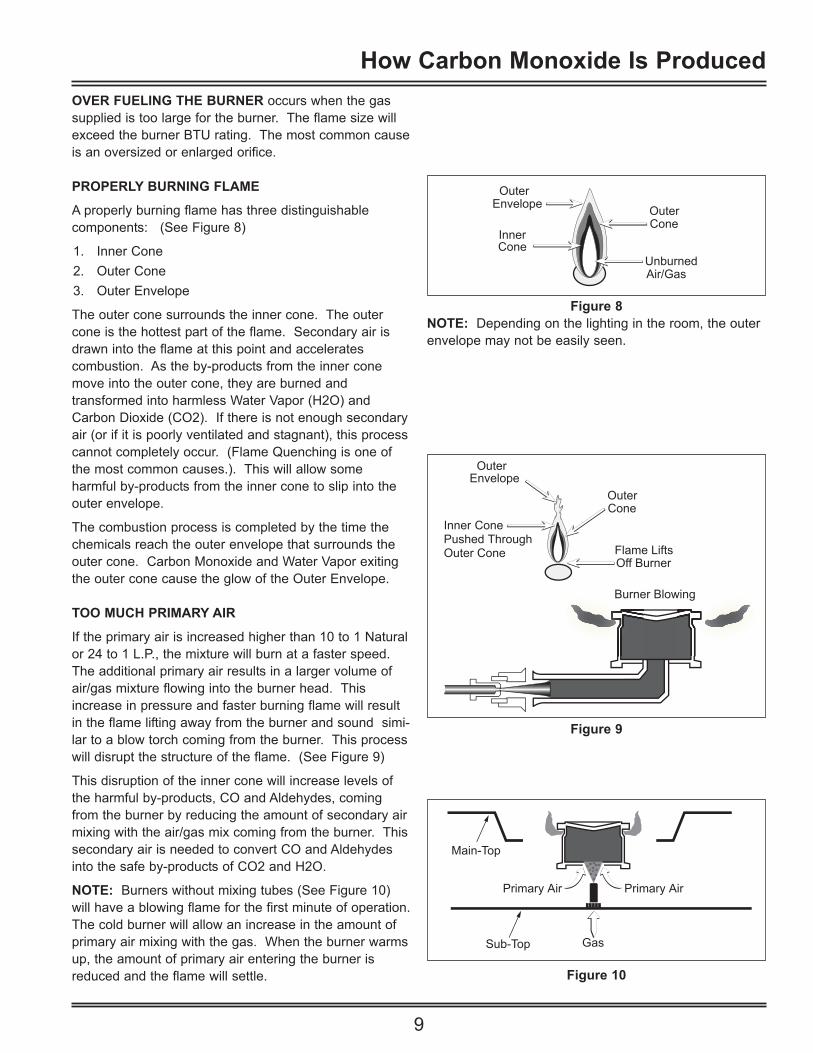
OVER FUELING THE BURNER occurs when the gassupplied is too large for the burner. The flame size willexceed the burner BTU rating. The most common causeis an oversized or enlarged orifice.
PROPERLY BURNING FLAME
A properly burning flame has three distinguishable components: (See Figure 8)
1. Inner Cone2. Outer Cone3. Outer Envelope
The outer cone surrounds the inner cone. The outercone is the hottest part of the flame. Secondary air isdrawn into the flame at this point and accelerates combustion. As the by-products from the inner conemove into the outer cone, they are burned and transformed into harmless Water Vapor (H2O) andCarbon Dioxide (CO2). If there is not enough secondaryair (or if it is poorly ventilated and stagnant), this processcannot completely occur. (Flame Quenching is one ofthe most common causes.). This will allow some harmful by-products from the inner cone to slip into theouter envelope.
The combustion process is completed by the time thechemicals reach the outer envelope that surrounds theouter cone. Carbon Monoxide and Water Vapor exitingthe outer cone cause the glow of the Outer Envelope.
TOO MUCH PRIMARY AIR
If the primary air is increased higher than 10 to 1 Naturalor 24 to 1 L.P., the mixture will burn at a faster speed.The additional primary air results in a larger volume ofair/gas mixture flowing into the burner head. Thisincrease in pressure and faster burning flame will resultin the flame lifting away from the burner and sound simi-lar to a blow torch coming from the burner. This processwill disrupt the structure of the flame. (See Figure 9)
This disruption of the inner cone will increase levels ofthe harmful by-products, CO and Aldehydes, comingfrom the burner by reducing the amount of secondary airmixing with the air/gas mix coming from the burner. Thissecondary air is needed to convert CO and Aldehydesinto the safe by-products of CO2 and H2O.
NOTE: Burners without mixing tubes (See Figure 10)will have a blowing flame for the first minute of operation.The cold burner will allow an increase in the amount ofprimary air mixing with the gas. When the burner warmsup, the amount of primary air entering the burner isreduced and the flame will settle.
Burner Blowing
EnvelopeOuterCone
ConeInner
Outer
Flame Lifts Off Burner
Pushed ThroughOuter Cone
Figure 9
Primary Air Primary Air
Sub-Top
Main-Top
Gas
Figure 10
Envelope OuterCone
ConeInner
UnburnedAir/Gas
Outer
Figure 8NOTE: Depending on the lighting in the room, the outerenvelope may not be easily seen.
How Carbon Monoxide Is Produced

10
TOO LITTLE PRIMARY AIR
A reduction in primary air will slow the burning processand result in the inner cone rising higher in the flame.This will cause less burning in the inner cone and allow alarger amount of by-products to pass into the outer cone.
This lack of air will cause the outer cone to decrease insize, and it will not consume the amount of by-productscoming from the inner cone. Some of these by-productsflow into the outer envelope, where the carbon is burned.This shows up as a yellow tipping on the top of the burner flame. (See Figure 11)
OVER FUELED BURNER
The over fueling of a burner may be caused by:1. Excessive gas pressure entering the burner.2. The BTU rating of the gas is too high for the burner.3. The metering orifice is too large for the burner.
It is difficult to determine if the burner is over fueled or ifit is getting too much primary air. Both cases will allowthe flame to lift away from the burner. (See Figure 12)
The most noticeable difference on an over fueled burneris that the flame is closer to normal, and the burner hasless of the blowing sound than what is present with toomuch primary air.
The best way to distinguish between an over fueledburner or too much primary air, is to open or close the airopening in the burner. If the closing of some of the airopening, therefore reducing the amount of air enteringthe burner, lowers the flame level to normal, the problemis too much primary air, not too much fuel.
If reducing the primary air does not correct the problem,turn the orifice hood down toward the valve while observing the flame. If this procedure brings the flameback to normal, the problem is an over fueled burner.
Top burners should have a cone length of approximately5/8". (See Figure 13)
Oven burners should have a cone length of approximately 5/8" with the oven bottom and flamespreader remover. (See Figure 14)
NOTE: Some lift off of the flame with the oven bottomand flame spreader removed is normal.
For L.P. installation of models without adjustable orifices,the range must have a L.P. conversion kit installed. Thiskit will contain the proper sized orifice, and on some burners, a new air shutter.
Yellow Tippingin Outer Envelope
OuterCone
ConeInner
UnburnedAir/Gas
Figure 11
Flame Lifts Off Burner
ConeLong InnerFlame
To Tall
Yellow Tips &Soot Can AppearIn Extreme Cases
Figure 12
OuterCone
5/8”
CooktopBurner
Figure 13
OuterCone5/8”
Bake/BroilBurner
Figure 14
How Carbon Monoxide Is Produced
11
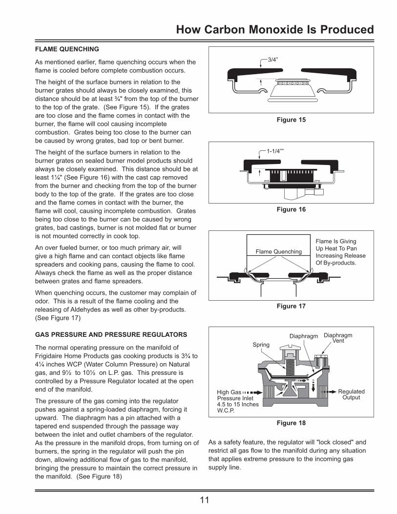
FLAME QUENCHING
As mentioned earlier, flame quenching occurs when theflame is cooled before complete combustion occurs.
The height of the surface burners in relation to the burner grates should always be closely examined, thisdistance should be at least ¾" from the top of the burnerto the top of the grate. (See Figure 15). If the gratesare too close and the flame comes in contact with theburner, the flame will cool causing incomplete combustion. Grates being too close to the burner can be caused by wrong grates, bad top or bent burner.
The height of the surface burners in relation to the burner grates on sealed burner model products shouldalways be closely examined. This distance should be atleast 1¼" (See Figure 16) with the cast cap removedfrom the burner and checking from the top of the burnerbody to the top of the grate. If the grates are too closeand the flame comes in contact with the burner, theflame will cool, causing incomplete combustion. Gratesbeing too close to the burner can be caused by wronggrates, bad castings, burner is not molded flat or burneris not mounted correctly in cook top.
An over fueled burner, or too much primary air, will give a high flame and can contact objects like flame spreaders and cooking pans, causing the flame to cool.Always check the flame as well as the proper distancebetween grates and flame spreaders.
When quenching occurs, the customer may complain ofodor. This is a result of the flame cooling and the releasing of Aldehydes as well as other by-products.(See Figure 17)
GAS PRESSURE AND PRESSURE REGULATORS
The normal operating pressure on the manifold ofFrigidaire Home Products gas cooking products is 3¾ to4¼ inches WCP (Water Column Pressure) on Naturalgas, and 9½ to 10½ on L.P. gas. This pressure is controlled by a Pressure Regulator located at the openend of the manifold.
The pressure of the gas coming into the regulator pushes against a spring-loaded diaphragm, forcing itupward. The diaphragm has a pin attached with atapered end suspended through the passage waybetween the inlet and outlet chambers of the regulator.As the pressure in the manifold drops, from turning on ofburners, the spring in the regulator will push the pindown, allowing additional flow of gas to the manifold,bringing the pressure to maintain the correct pressure inthe manifold. (See Figure 18)
3/4”
Figure 15
1-1/4””
Figure 16
Flame Quenching
Flame Is GivingUp Heat To PanIncreasing ReleaseOf By-products.
Figure 17
Figure 18
As a safety feature, the regulator will "lock closed" andrestrict all gas flow to the manifold during any situationthat applies extreme pressure to the incoming gas supply line.
How Carbon Monoxide Is Produced

12
MEASURING GAS PRESSURE
Gas pressure in the home is measured in Inches ofWater Column Pressure (WCP). It takes 28 inches WCPto equal 1 Pound per Square Inch (PSI).
In most locations, natural gas pressure coming into thehouse is regulated between 6 and 7 inches WCP. Theregulator on a home L.P. tank in most locations is set at11 to 13 inches WCP. The regulator on the product isset to bring the pressure down to the product manufacturer's recommended manifold pressure.
NOTE: There are some areas where the gas supplypressure can drop as low as 2 to 3 inches WCP, usuallyduring the winter. If the service technician finds thepressure below 3½ inches on natural gas or 9½ incheson L.P., the product will not work properly. There is nothing the technician can do except show the customerthe low pressure problem and advise the customer tocontact the gas company or a plumber.
A manometer is used to measure gas pressure in inchesof water column. (See Figure 19). A manometer is aclear tube shaped like the letter "U". The tube has marking starting at zero across from each other, andgoing up one inch at a time on one side, and down oneinch at a time on the other side. To use a manometer, fillwith water until both tubes are at "0". You may want toadd a little food coloring to the water to make reading thegauge easier. Connect the tubing (supplied with themanometer) over one end of the manometer, and theother end of the tube to the burner orifice at the end ofthe manifold. (Usually the Left Rear Burner). Turn theburner on, observe the movement of the water. The gaspressure is read by adding the inches of movement inboth legs of the gauge. (See Figure 20) Now turn onthe rest of the burners, checking the pressure each timeyou turn on another burner.
EXAMPLE: If the manometer shows a reading of 2inches below "0" on one side, and 2 inches below "0" onthe other, you add up the two together and you get areading of 4 inches WCP.
Another gauge used to measure gas pressure is themagnehelic gauge. (See Figure 21) This is a simplerand faster gauge to use to make pressure readings.Connect the rubber tube on the gauge to the burner orifice, turn on the burner and read the pressure.
0123456
123456
Figure 19
0123456
123456
Gas Pressure
Figure 20
INCHES OF WATER
OUNCES
MAGNEHELIC
2 4 68
10515
Figure 21
How Carbon Monoxide Is Produced

13
APPLIANCE REGULATOR TEST
Check the data plate on the product and find the recommended operating pressure before attempting tocheck the pressure.
Connect the manometer to the burner orifice at the endof the manifold. (Usually the Left Rear Burner) Turn theburner on, observe the gas pressure. Now turn on therest of the burners, one at a time, checking the pressureeach time you turn on another burner. The pressureshould not fall more than ½ inch below the require operating pressure listed on the product data plate. Ifthe pressure is low, you need to check the pressure onthe supply line under flow. If the supply line pressure isgood, but the manifold pressure is bad, replace the regulator. If the supply line pressure is low, show thecustomer and advise them to contact the utility company.
TESTING FOR CARBON MONOXIDE IN THE HOME
There are a number of Combustion Analyzers on themarket today, some are better than others. TheBacharach Model PCA-12 is one of the better analyzers.J and N Enterprizes also makes some good models, theUltra-trac 2000, the TKX-7, and the Trak-It Dm Series.The Trak-It Dm Series features direct reading using anydigital Multimeter (800-820-9792).
As with any Meter or Analyzer read the operation manualsupplied with the instrument. Know and understand howto use the instrument before going to a Customers hometo test for Carbon Monoxide. Follow manufacturers recommend calibration procedures.
BACHARACHCO (Air Free) 15 RCO (Diluted) 12 Oxygen 4.0 PTemperature 370 S
Portable Combustion Analyzer
ENTER
PCA
RUN
MENU
LIGHT
ONOFF
TO TEST FOR CARBON MONOXIDE:
1. Determine the type of fuel being used, Natural Gas or L.P.
2. Program the oven to bake at 500°. (Set oventhermostat to the highest setting to avoid oven burners cycling off during test)
3. Allow oven to cycle for 7 minutes before attempting to measure the CO. (Do not Test or Hold Equipment on or around the oven during the warm-up period.)
4. After the 7 minute warm up period, run test per the recommendation of the equipment manufacturer.
5. Record your test results on the service invoice.
Measurements must be within ANSI (American NationalStandards Institute) standards:
800 PPM CO AIR-FREE
If test results of CO Air-Free are above 400 PPM checkto see all adjustments are correct.
COOKTOP MEASUREMENTS
You can not check CO levels from the surface burners inthe field. Check that all surface burners for yellow tipping, loud sound (blow torch), and check pilot lightadjustment if applicable. Make any necessary adjustments needed to obtain proper flame. Checkburner to grate height for proper spacing. (See page 11)
How Carbon Monoxide Is Produced

14
ADJUSTMENT AND REPAIR PROCEDURES
BAKE BURNER ADJUSTMENT
Depending on the style of the range, adjustment of theBake Burner may be accomplished as follows:1. If a bake burner has an adjustable air shutter and
broil drawer under oven:Open broiler drawer and turn on oven. Observe the burner for length and color of flame. Length of flame should be ¾ to 1" total length with an inner cone of about ½". There should be no yellow tips on natural gas, and very little on products installed on L.P.
2. If the flame is yellow:First check alignment of burner and orifice. Next, open air shutter until you get a good flame. If opening the air shutter does not help, adjust the orifice down until you get a good flame. (See Figure 23)
3. If the flame is lifting off the burner: Close the air shutter until you get a good flame. If you have problems getting a good flame, check yourgas pressure.
BROIL BURNER ADJUSTMENT
On products with broil burners mounted in the top of the oven, adjustment of the Broil Burner may be accomplished as follows:
1. If broil burner has an adjustable air shutter: (See Figure 23)Turn on oven to broil. Observe the burner for length and color of flame. Length of flame should be ¾” to1" in total length with an inner cone of about ½". There should be no yellow tips on natural gas and very little on products installed on L.P.
2. If the flame is yellow:First check alignment of burner and orifice. Next, open air shutter until you get a good flame. If opening the air shutter does not help, adjust the orifice down until you get a good flame.
3. If the flame is lifting off the burner:Close the air shutter until you get a good flame. If you have problems getting a good flame, check yourgas pressure.
Air/GasMixing
PrimaryAir
PrimaryAir
Gas
SafetyValve
Oven Burner
Air Shutter Location(Adjustable or Fixed)
Figure 23
Adjustment And Repair Procedures

15
CONVENTIONAL SURFACE BURNERS
NOTE: Check the height of the burner in relation to thegrate before making any adjustment. The product musthave ¾" from the top of the burner to the top of thegrate. If the burner is too close to the grate, check for abent burner and/or bracket, deformed burner box orincorrect grates. (See Figure 24)
1. Turn burner on high; observe the burner for length and color of flame. Length of flame should be ¾" in total length with an inner cone of about ½". There should be no yellow tips on natural gas, and verylittle on products installed on L.P.
2. If the flame is yellow; first check alignment of burner and orifice. Next, open air shutter until you get a good flame. If opening the shutter does not help, adjust the orifice down until you get a good flame.
3. If the flame is lifting off the burner; close the air shutter until you get a good flame. If you have problems getting a good flame, check your gas pressure.
If the burner does not have an adjustable air shutter:
1. Turn the burner on high; observe the burner for length and color of flame. Length of flame should be¾" in total length with an inner cone of about ½". There should be no yellow tips on natural gas, and very little on products installed on L.P.
2. If the flame is yellow; check alignment of burner and orifice. If alignment is good, adjust the orifice down until you get a good flame.
If you still have problems getting a good flame, check thegas pressure.
If the flame is lifting off the burner; adjust the orificedown until you get a good flame. If you have problemsgetting a good flame, check the gas pressure.
NOTE: Most gas ranges are shipped set for natural gasinstallation, and must be converted for use on L.P. gas.When you are having problems with a gas range connected to L.P. gas:
1. Check the regulator to see that it was converted to L.P. use.
2. Check the gas pressure (Should be between 9½ and 10½" WCP at the burners under flow.)
3. On standard burner models; is the outer spud turneddown against the inner pin, (See Figure 25), or is it turned down so tight that the inner pin is damaged?
4. On sealed burner models, was the orifice changed tothe proper orifice?
3/4”
Figure 24
Natural Gas
L.P. Gas Increase GasIncreases Flame Size(Pre-Set at Factory
For Natural Gas) Decrease GasDecreases
PinSpud
Flame Size
Figure 25
Adjustment And Repair Procedures

16
SEALED BURNERS
Sealed burners are secured to the cook top and requireless secondary air than conventional burners. Thereduced secondary air requirement eliminates the needfor the large opening surrounding the burner. The primary air mixes with the gas in the venturi of the burner. (See Figure 26)
The burner consists of two parts, the burner base andthe burner cap. The orifice is not adjustable and thereare no adjustable air shutters. There is an individualspark electrode for each burner. (See Figure 27)
If the burner flame appears to be abnormal, check thefollowing:1. Check the gas pressure. (Natural 3¾ to 4¼ WCP,
L.P. gas 9½ to 10½ WCP)2. Make sure the range is set for the proper type gas
being used for operation.3. Check the burner cap by pushing down and turning
back and forth.4. Check for a draft that may be entering under the top
and extinguishing the burner flame.5. Check for a partial or total blockage of the orifice.
SURFACE BURNERS DO NOT OPERATE PROPERLYWHEN OVEN IS IN OPERATION (This can apply to allranges.)
If the complaint is that the surface burners work properlywhen the oven is off, but do not operate properly whenthe oven is on; this is an indication that the oven is venting by-products from the oven under the range top.Check for the following possible cause:1. Check the oven vent to see that it is above the range
top. Model with vent coming into a grill in lift up range top.
2. Check position of insulation around oven liner and vent to see if in proper location. (See Figure 27)
3. Check oven vent for separation, or bad seal betweenvent and oven liner.
4. Check oven door and seal alignment.
Seal
Orifice
Burner CapIgnitor
Figure 26
Vent OpeningIn Cook Top
Insulation
Oven Vent
Seal BetweenVent And LinerFront Face
Oven Liner
Figure 27
Adjustment And Repair Procedures

17
CUSTOMER RELATIONS ISSUESWhen a consumer calls with a carbon monoxide safetyconcern, a service call to check for the cause and correction of the CO problem should be provided within24 hours of receiving the complaint. Also advise not touse range.
All safety related inspection will be provided free ofcharge to the consumer. Process all safety relatedclaims as a "SPECIAL AUTHORIZATION". List as service Policy # in the special authorization space of theService Invoice Form and process it as any other warranty claim. Record the CO readings before andafter the repair on the Service Invoice, and obtain customer signature.
RED TAGGED PRODUCTS
When a product has been "Red Tagged" by a UtilityCompany because of unsafe Carbon Monoxide levels,the technician should inspect and repair the product.Then instruct the customer to call the Utility Companywith the test results of the service call and have theproduct placed back into service.
If, after testing and adjustment procedures are performed, the CO level is still high, contact theConsumer Assistance Center (CAC) and advise of theproblem. Document all CO readings and repairs on theService Invoice and fax a copy to the TechnicalInformation Department (TID).
EXPLAINING INSPECTIONS RESULTS TO THE CONSUMER
The difference in CO Detection Equipment and themethod used to check the product can be very confusingto the consumer. The problem could be worse than theythought, or it may not be a problem at all.
Many consumers who become aware of elevated COlevels in their homes will call a professional to inspectthe situation, and try to find the source. They will bemost likely looking for infractions to the EPA ambient airCO level guidelines. These professionals, who are oftenFiremen or technicians from the local utility company,may be monitoring the "Diluted CO" measurementsrather than the CO A/F (undiluted) measurement, whichis more accurate.
When you are called to inspect a Gas Range, it isimportant to make your own readings and be sure to findthe CO A/F readings as the original readings may havebeen taken CO only. CO only readings are not recognized by the American National Standards Institute(ANSI). When explaining this situation to the customer, itis important to give them a basic understanding of thetwo measurement systems, (diluted vs. undiluted) andexplain to them the reasons they are both used.
If a home has a high level of CO in its ambient air, itcould be caused by many factors. Any gas burningappliance might emit some level of Carbon Monoxide;cigarette smoke, car exhaust, and wood burning fireplaces can all be causes of elevated CO in the home. If a number of CO sources are present in the area withpoor ventilation, it could cause high levels of CO withoutbreaking any standards for emissions from any oneappliance. It is possible that a range is a factor in aproblem, but it is not the only factor.
If a product is tested by a technician and found to beoperating above the ANSI standard of 800 PPM CO A/F,then the product must be repaired. If a product is testedby a technician and found to be operating at or below theANSI standard of 800 PPM CO A/F, then it must beexplained to the customer that the level of CO in theambient air might be high, but it is not because of a malfunctioning Gas Range. It could be from a combination of low-level CO sources, or from poor ventilation.
Consumer Relations Issues

18
Notes
Electrolux Major Appliances Publication # 5995304697