3.4 proposed tower solutions - applied and...
TRANSCRIPT
62 | 3.4
3.4 Proposed Tower Solutions - Applied and Theoretical Plans
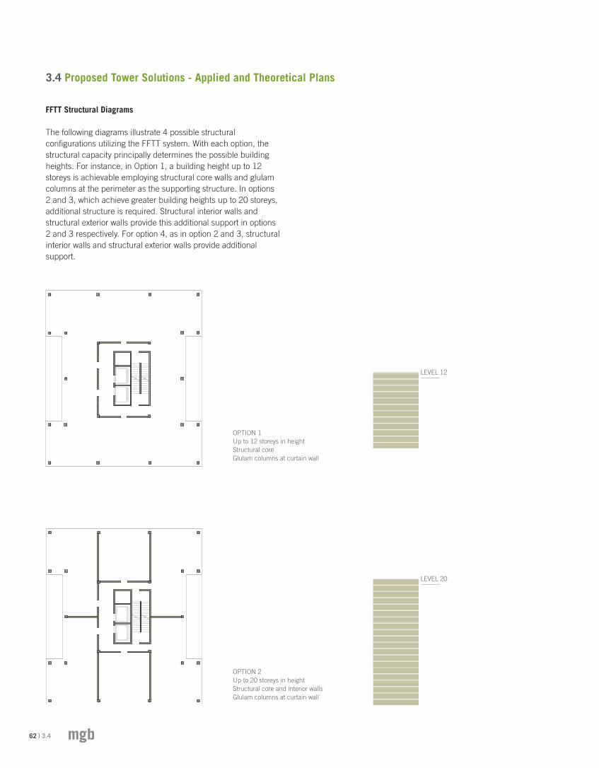
OPTION 1Up to 12 storeys in heightStructural core Glulam columns at curtain wall
OPTION 2Up to 20 storeys in heightStructural core and interior walls Glulam columns at curtain wall
LEVEL 12
LEVEL 20
FFTT Structural Diagrams
The following diagrams illustrate 4 possible structural configurations utilizing the FFTT system. With each option, the structural capacity principally determines the possible building heights. For instance, in Option 1, a building height up to 12 storeys is achievable employing structural core walls and glulam columns at the perimeter as the supporting structure. In options 2 and 3, which achieve greater building heights up to 20 storeys, additional structure is required. Structural interior walls and structural exterior walls provide this additional support in options 2 and 3 respectively. For option 4, as in option 2 and 3, structural interior walls and structural exterior walls provide additional support.

3.4 | 63THE CASE FOR Tall Wood BUILDINGS
OPTION 3Up to 20 storeys in heightStructural core and exterior walls
OPTION 4Up to 30 storeys in heightStructural core, interior walls or exterior walls
LEVEL 20
LEVEL 30

64 | 3.4
OPTION 1 - Up to 12 Storeys
Building envelope
Glulam columns + steel/glulam beams
Concrete below grade
Structural core (wood)
Building envelope
Glulam columns + steel beams
Concrete below grade
Structural core (wood)
Structural interior walls
OPTION 2 - Up to 20 Storeys
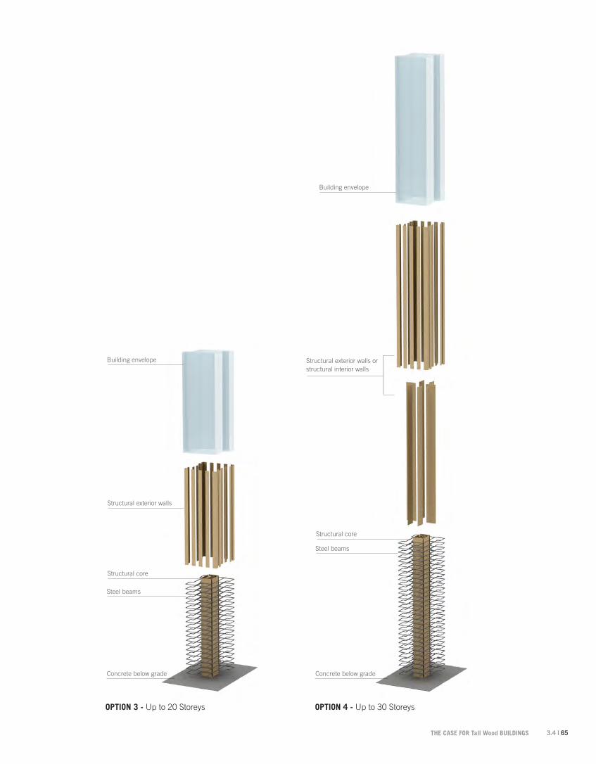
FFTT Axonometric Diagrams
3.4 | 65THE CASE FOR Tall Wood BUILDINGS
Building envelope
Steel beams
Concrete below grade
Structural core
Structural exterior walls
Building envelope
Structural exterior walls or structural interior walls
Steel beams
Concrete below grade
Structural core
OPTION 3 - Up to 20 Storeys OPTION 4 - Up to 30 Storeys

66 | 3.4
OPTION 3 - Up to 20 Storeys OPTION 4 - Up to 30 StoreysOPTION 1 - Up to 12 Storeys OPTION 2 - Up to 20 Storeys
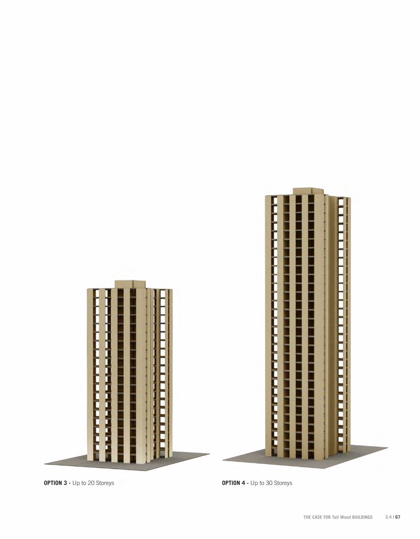
Implied Architectural Impact as Result of the Structure
The structural configurations, in addition to determining the achievable building heights will impact both the design of the envelope and floor plan of the building. For example, Option 1 offers the greatest amount of flexibility in the design of its interior partitioning. This structural configuration bears closest resemblance to the typical concrete benchmark in that it utilizes a structural core and perimeter columns that affords it a free-plan. In options 3 and 4, where additional structure is required for the increase in building height, constraints are placed on the design of either the interior partitions or envelope. As a result, these configurations can be more advantageously applied to specific uses. For instance, where interior walls are utilized as structure, a residential application would be appropriate where these structural walls could double as unit demising walls.
3.4 | 67THE CASE FOR Tall Wood BUILDINGS
OPTION 3 - Up to 20 Storeys OPTION 4 - Up to 30 StoreysOPTION 1 - Up to 12 Storeys OPTION 2 - Up to 20 Storeys

68 | 3.4
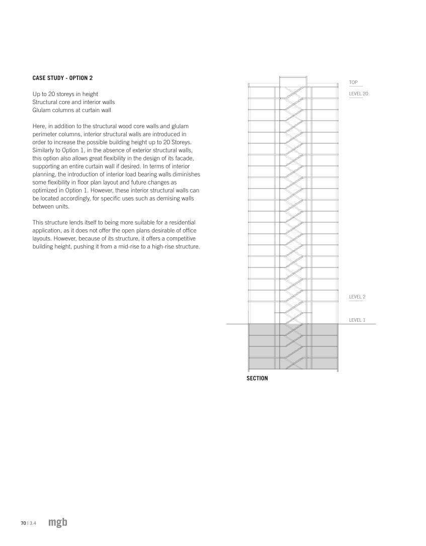
LEVEL 2
LEVEL 1
LEVEL 12
TOP
SECTION
CASE STUDY - OPTION 1
Up to 12 storeys in heightStructural core Glulam columns at curtain wall
In this option, which allows up to 12 storeys in building height, the wood core walls and glulam perimeter columns are deployed as the supporting structure. Since none of the interior walls are required to have a load bearing function, a great amount of flexibility is afforded in terms of floor plan layout. As well, in the absence of exterior load bearing walls, this option allows flexibility in the design of its façade, including the ability to support an entire curtain wall envelope if desired.
Additionally, like many buildings with such open spaces, interior modifications are easily made to allow for future changes in occupancy or use. Its open floor plan and ability to easily accommodate future changes positions this option quite competitively in terms of use and planning to its concrete benchmark, particularly in the office market.

3.4 | 69THE CASE FOR Tall Wood BUILDINGS
Unit 1
750 SF
Unit 2
550 SF
Unit 3
750 SF
Unit 4
750 SF
Unit 5
550 SF
Unit 6
750 SF
Uni
t 4
Bal
cony
Uni
t 1
Bal
cony
Uni
t 6
Bal
cony
Uni
t 3
Bal
cony
Glulam columnSteel beam
Structural core
Glulam beam
PLAN OPTION 1Refer to Section 3.6 Structural Intent for structural information
70 | 3.4
CASE STUDY - OPTION 2
Up to 20 storeys in heightStructural core and interior walls Glulam columns at curtain wall
Here, in addition to the structural wood core walls and glulam perimeter columns, interior structural walls are introduced in order to increase the possible building height up to 20 Storeys. Similarly to Option 1, in the absence of exterior structural walls, this option also allows great flexibility in the design of its facade, supporting an entire curtain wall if desired. In terms of interior planning, the introduction of interior load bearing walls diminishes some flexibility in floor plan layout and future changes as optimized in Option 1. However, these interior structural walls can be located accordingly, for specific uses such as demising walls between units.
This structure lends itself to being more suitable for a residential application, as it does not offer the open plans desirable of office layouts. However, because of its structure, it offers a competitive building height, pushing it from a mid-rise to a high-rise structure.
LEVEL 2
LEVEL 1
LEVEL 20
TOP
SECTION

3.4 | 71THE CASE FOR Tall Wood BUILDINGS
Unit 1
750 SF
Unit 2
550 SF
Unit 3
750 SF
Unit 4
750 SF
Unit 5
550 SF
Unit 6
750 SF
Uni
t 4
Bal
cony
Uni
t 1
Bal
cony
Uni
t 6
Bal
cony
Uni
t 3
Bal
cony
Glulam columnStructural core
Steel beam
Structural wall
PLAN OPTION 2Refer to Section 3.6 Structural Intent for structural information.

72 | 3.4
CASE STUDY - OPTION 3
Up to 20 storeys in heightStructural core and exterior walls
This option is similar to Option 2, with a maximum achievable building height of 20 storeys. This is accomplished utilizing structural wood core walls and introducing exterior structural wood walls. Here, the exterior structural walls have replaced the interior structural walls and perimeter glulam columns in Option 2.
The impact of this is that the plan is now structure free, again allowing flexibility in terms of interior partitioning and allowing future interior modifications. On the other hand, the presence of the exterior structural walls now limits the flexibility of the facade. For example, where solid structural walls occur, it would not be possible to have vision glass. As a result of this structure, punched or bay windows would be most suitable. Additionally, from a thermal performance point, these exterior walls provide opportunities for greater insulating assemblies.
This structure would be particularly suitable for residential applications in consideration of its exterior structure and facade composition. While, its open interior plan would be suitable for an office arrangement, it would be challenged in the office market because of its obstructed views and amount of daylight the interior receives relative to its concrete benchmark which can utilize a completely glazed curtain wall. Again, like Option 2, it offers a competitive building height at 20 storeys.
LEVEL 2
LEVEL 1
LEVEL 20
TOP
SECTION

3.4 | 73THE CASE FOR Tall Wood BUILDINGS
Unit 1
750 SF
Unit 2
550 SF
Unit 3
750 SF
Unit 4
750 SF
Unit 5
550 SF
Unit 6
750 SF
Uni
t 4
Bal
cony
Uni
t 1
Bal
cony
Uni
t 6
Bal
cony
Uni
t 3
Bal
cony
Steel beam
Structural core
Steel ledger
Structural wall
PLAN OPTION 3Refer to Section 3.6 Structural Intent for structural information
Note: Our analysis has shown that a 30 storey model performed adequately with either the interior partition walls or perimeter frame.

74 | 3.4
CASE STUDY - OPTION 4
Up to 30 storeys in heightStructural core, interior walls and exterior walls
This option pushes the maximum building height to 30 storeys. To do so, it utilizes structural core walls, structural interior walls and structural exterior walls. As a result, it offers the least flexibility of the four options. Its interior structural walls would limit it to residential use, as in Option 2, its exterior structural walls would limit the envelope options as discussed in earlier in Option 3.
The primary advantage of this option is its building height. However, the structure that is required to achieve this height becomes disadvantageous to its planning and design flexibility. As a result, this option is limited in its flexibility and use.
LEVEL 2
LEVEL 1
LEVEL 30
TOP
SECTION
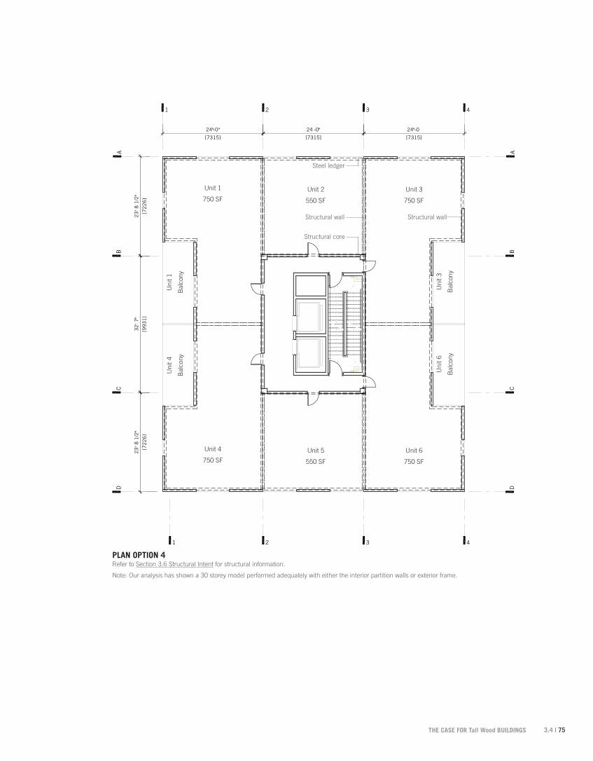
3.4 | 75THE CASE FOR Tall Wood BUILDINGS
Unit 1
750 SF
Unit 2
550 SF
Unit 3
750 SF
Unit 4
750 SF
Unit 5
550 SF
Unit 6
750 SF
Uni
t 4
Bal
cony
Uni
t 1
Bal
cony
Uni
t 6
Bal
cony
Uni
t 3
Bal
cony
Structural core
Steel ledger
Structural wall Structural wall
PLAN OPTION 4Refer to Section 3.6 Structural Intent for structural information.
Note: Our analysis has shown a 30 storey model performed adequately with either the interior partition walls or exterior frame.
76 | 3.5
3.5 Architectural Application of an Idea
The FFTT system is designed and considered as a universal structural system to engineer Tall Wood buildings. However, it is important to understand that it has also been driven by a number of architectural issues pertinent to tall buildings that are crucial to the system’s success. The FFTT system allows for flexibility in tower planning and facade design with some decrease in flexibility once the system is utilized in applications above 20 storeys. Above this height, an FFTT tower would likely be limited to residential use. The flexibility in tower planning is important for a number of reasons:
1. An open plan (where there are no interior structural partition walls) allows for a variety of uses including office or residential.
2. An open plan (where there are no interior structural partition walls) allows for future modifications as uses and tenants change.
3. Developers typically look to flexibility in the structural system to ensure they can manipulate the solution to meet their market goals. Open plans give enormous design flexibility to the developers and architects.
4. Exterior character and massing are important to adjust to the specifics of a given site, setback requirements, views and view corridors, shadowing conditions or architectural expression.
In addition to these considerations, a review of acoustic and vibration conditions, systems integration, life safety, fire and finishing relevant to tower construction follow in subsequent sections. In summary, what we have found is that there are no obstacles with FFTT to satisfying the typical needs of a tower design leaving possibilities open to the imagination of all architects.
3.5 | 77THE CASE FOR Tall Wood BUILDINGS
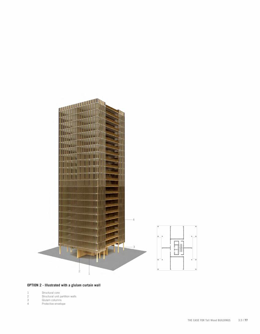
1 Structural core2 Structural unit partition walls 3 Glulam columns4 Protective envelope
OPTION 2 - Illustrated with a glulam curtain wall
12
3
4

78 | 3.5
OPTION 2 - Illustrated with a glulam curtain wall and corner balconies
1 Structural core2 Structural unit partition walls 3 Glulam columns4 Protective envelope5 Corner balcony
12
3
4
5