3/4 lvl reinforced joining guide
TRANSCRIPT

3/4" LVL Reinforced Joining Guide (1-Way Vertical Joining) or (1-Way Horizontal Joining)
“Andersen” and all other marks where denoted are marks of Andersen Corporation. ©2004-2007 Andersen Corporation. All rights reserved.0005382 BD Revised 11/24/08
3/4" LVL Reinforced Joining Guide (1-Way Vertical Joining) or (1-Way Horizontal Joining)for Andersen® 400 Series Tilt-Wash Double-Hung, Picture, and Transom Windows and Narroline® Circle Top™ Windows with Stormwatch® Protection.
1-Way Vertical Joining (Pages 2-22)
1-Way Horizontal Joining (Pages 23-44)
• Notallpartsincludedwillbeused.• Checkspecifichorizontalorverticaljoiningsectioninthisguideforpartsneeded.• Properlydisposeofunusedparts.
1

3/4" LVL Reinforced Joining Guide (1-Way Vertical Joining)
Windows and doors can be heavy. Use safe lifting techniques and a reasonable number of people with enough strength to lift, carry and install window and door products to avoid injury and/or product damage.
Use caution when working at elevated heights and around unit openings. Follow manufacturer’s instructions for safe use of ladder and/or scaffolding. Failure to do so may result in injury or death.
Follow manufacturer’s instructions for safe operation of hand/power tools. Always wear safety glasses. Failure to do so may result in injury and/or product damage.
Impact Resistant Glass used by Andersen is not hurricane proof or shatter proof, and may not offer a high level of security. Proper installation of window and door units with impact resistant glass is as important to product performance as the glass. Every assembly and installation is different (windloads, structural support, etc.), and Andersen strongly recommends consultation with an Andersen supplier or an experienced contractor, architect, or structural engineer prior to the assembly and installation of any Andersen product. Andersen has no responsibility in regard to the post-manufactured assembly and installation of Andersen products.
Congratulations! You have just purchased one of the many fine Andersen® products. Proper assembly, installation and maintenance are essential if the benefits of your Andersen product are to be fully attained. Therefore, please read and follow this Instruction Guide completely. If your abilities do not match this procedure’s requirements, contact an experienced contractor. You may direct any questions about this or other products to your local Andersen dealer, found in the Yellow Pages under “Windows” or call Andersen WindowCare® service center at 1-888-888-7020 Monday through Friday, 7 a.m. to 7 p.m. Central Time and Saturday, 8 a.m. to 4 p.m. Central Time. Thank you for choosing Andersen.
• Andersen® Installation Flanges DO NOT take the place of standard window and door flashing. Unit must be properly flashed and sealed with sealant, and full width drip cap for protection against water and air infiltration. Use non-reflective flashings. Highly reflective flashing tapes can raise the surface temperature of the vinyl to the point where vinyl deformation and product damage may occur.
• Donotapplyanytypeoffilmtoglass.Thermalstressconditionsresultinginglassdamagecouldoccur.
• Useofmovableinsulatingmaterialssuchaswindowcoverings,shutters,andothershadingdevicesmaydamageglass and/or vinyl. In addition, excessive condensation may result causing deterioration of windows and doors.
Unless specifically ordered, Andersen windows and doors are not equipped with safety glass, and if broken, could fragment causing injury. Many laws and building codes require safety glass in locations adjacent to or near doors. Andersen windows are available with safety glass that may reduce the likelihood of injury when broken. Information on safety glass is available from your local Andersen dealer.
2 Revised 11/24/08
3/4" LVL Reinforced Joining Guide(1-Way Vertical Joining)for Andersen® 400 Series Tilt-Wash Double-Hung, Picture, and Transom Windows with Stormwatch Protection
“Andersen” and al l other marks where denoted are trademarks of Andersen Corporation. ©2004-2007 Andersen Corporation. Al l r ights reser ved.

Metal fasteners and other hardware components may corrode when exposed to preservative treated and fire-retardant treated lumber. Obtain and use the appropriate metal fasteners and hardware as called out by the installation guide to fasten unit to any rough opening made from pressure treated and fire-retardant treated lumber. Failure to use the appropriate materials for the installation may cause a failure resulting in injury, property or product damage.
Tools and Supplies•SafetyGlasses•TapeMeasure•Pencil•Level•Hammer•Clamps•PowerDrill•CaulkGun•HackSaw•WoodBlock
Parts Included(1) Instruction Guide(1) Head Gusset Plate(1) Sill Gusset Plate(1) 3/4"LVLJoiningStrip(1) Exterior Trim Strip(1) Installation Screw Pack
Component Identification
Use this guide to join two or more units vertically.
3/4"LVLJoiningStrip
Exterior Trim Strip
Head Gusset Plate Sill Gusset Plate
Exterior Views
Additional Parts Required•DripCap(fullwidth)
•Sealant•ViseGrip/Pliers•SmallPryBar•3/8"WoodShims•PowerSaw•SmallFile/Rasp•3/32"DrillBit•UtilityKnife•IsopropylAlcohol
3/4" LVL Reinforced Joining Guide (1-Way Vertical Joining)
3

1. Verify that LVL Joining is Adequate for Your Installation• Calculatetheaverageadjacentunitdimension((A+B)÷2).• Determinethemullionlength(C).• Usethewindloadchartbelowtocrossreferencetheaverage
adjacent unit dimension with the mullion length to determine the windload performance of your combination.
• Besurethatthisperformanceisadequateforyourinstallationrequirements.
• RefertotheCombinationDesignsectionintheAndersen ® Product Guide for Professionals for further information.
Design Windload PSF Table for 3/4" LVL Reinforced JoiningType of Combination: Vertical JoiningFor Combining: Tilt-Wash Double-Hung, Transom, or Picture Windows
PSF
(A + B) ÷ 2 = 6' 1" 82 70(A + B) ÷ 2 = 5' 6" 82 71(A + B) ÷ 2 = 5' 1" 82 72(A + B) ÷ 2 = 4' 6" 82 75(A + B) ÷ 2 = 4' 1" 82 79(A + B) ÷ 2 = 3' 6" 82 82 (A + B) ÷ 2 = 3' 1" 82 82(A + B) ÷ 2 = 2' 6" 82 82(A + B) ÷ 2 = 2' 1" 82 82(A + B) ÷ 2 = 1' 6" 82 82Av
erAg
e
ADjA
cenT
U
niT
Di
men
Sion
C = (mullion length)
Double-Wide Unit
Picture Window with Flanking Units
Exterior View
Exterior View
5' 6"or less
6' 1"
3/4" LVL Reinforced Joining Guide (1-Way Vertical Joining)
4

3. Prepare Units• Placeunitsexteriorsideuponaclean,flat
work surface.• RemoveInstallation Flange from sides of units
to be joined.• Removeanddiscardprotruding3"screwfrom
Outer Frame Member Bracket on Tilt-Wash Unit sides to be joined.
• Removebandingtapefrom double-hung units.• ForExtension Jambapplication, see step 17.
2. Prepare Rough Opening•Determineroughopeningwidthformultiple
units using the formula: rough opening width = 3/8" (shim)+ total unit width(s) + 3/4" for each join(LVLJoiningStrip)+ 3/8" (shim).
•Determineroughopeningheightusingtheformula: rough opening height = 3/8" (shim) + unit height + 3/8" (head clearance).
•Checkroughopeningforplumbandlevel.Ifrough opening is not plumb or level, correct as necessary.
•Checkopeningforsquarebymeasuringdiagonally, upper left to lower right and upper right to lower left corner. If measurements are within 1/8", opening is square. If rough opening is not square, correct as necessary.
Exterior View
Tilt-Wash Unit
3/4"LVLJoiningStrip
Head Gusset Plate
Exterior Side Up
Exterior Side Up
Sill Gusset Plate
Double-Wide Unit
Picture Window with Flanking Units
Triple-Wide Unit
Exterior Side Up
Picture Unit
Tape Measure
Level
OuterFrameMemberBracket(Remove 3" Screw)
Head
Sill
Remove Installation Flange
Remove Installation Flange
3/4" LVL Reinforced Joining Guide (1-Way Vertical Joining)
5
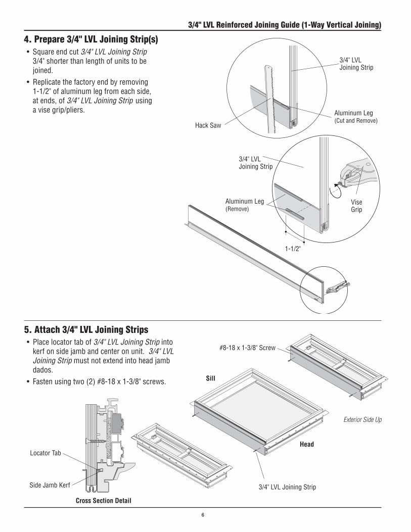
4. Prepare 3/4" LVL Joining Strip(s)• Squareendcut3/4" LVL Joining Strip
3/4" shorter than length of units to be joined.
• Replicatethefactoryendbyremoving1-1/2" of aluminum leg from each side, at ends, of 3/4" LVL Joining Strip using a vise grip/pliers.
5. Attach 3/4" LVL Joining Strips • Placelocatortabof3/4" LVL Joining Strip into
kerf on side jamb and center on unit. 3/4" LVL Joining Strip must not extend into head jamb dados.
• Fastenusingtwo(2)#8-18x1-3/8"screws.
AluminumLeg(Remove)
3/4"LVLJoiningStrip
#8-18x1-3/8"Screw
3/4"LVLJoiningStrip
Exterior Side Up
ViseGrip
1-1/2"
Head
Sill
Cross Section Detail
LocatorTab
SideJambKerf
AluminumLeg(Cut and Remove)
3/4"LVLJoiningStrip
Hack Saw
3/4" LVL Reinforced Joining Guide (1-Way Vertical Joining)
6

6. Join Units
• Slideunitstogether.Exteriornoseofunitsandside jambs must be flush full length.
• Clampunitstogether,fromtheexterior,usingclamps and surface protectors.
• Drill3/32"holes,at22˚ontheOuterFrameMember, 4" from head and sill, no deeper than 2-1/4". Offset holes 1/4" on adjacent units to avoid screw interference.
• Fastenunitsusing#10x2-1/2"colormatchedscrews with ring washers.
• Exteriornoseofunitsandsidejambsmustbe flush full length. If not flush, there will not be a proper seal and water infiltration may result.
• DONOTovertightenclamps,excesstightening of clamps may mar surface.
• UpperunitInstallationFlangemustoverlaplower unit Installation Flange to the exterior on horizontal joins. Failure to do so may adversely affect product performance.
Clamp#10x2-1/2"Screw
Exterior Side Up
Cross Section DetailDouble-HungtoDouble-Hung
Cross Section DetailPictureWindowtoDouble-Hung
22º
22º 22º
Outer Frame MemberRing Washer
22º
Outer Frame Member
#10x2-1/2"Screw
Ring Washer
DrilledHole DrilledHole
DrilledHole
DrilledHole
Head
Sill
3/4" LVL Reinforced Joining Guide (1-Way Vertical Joining)
7

6. Join Units (Continued)
• Ononeoftheunitsbeingjoinedmovethe1-1/4"screwremainingintheCheckrailBracketfromitscurrentholetotheotherholeintheCheckrailBracketwherethe3"screw was removed in Step 3. Moving this screw will makesurethatthescrewsontheCheckrailBracketonthe adjacent unit do not interfere with the screws on thisCheckrailBracket.
• Drilla3/32"hole,nodeeperthan2-1/2"deep,inthehole where the screw was just removed.
• FastentheremainingCheckrailBracketholewitha#10x2-1/2"colormatchedscrew.
• Placea#10x2-1/2"colormatchedscrewintheemptyCheckrailBracketholeontheotherunit.
Clamp#10x2-1/2"Screw
Exterior Side Up
Double-Hung to Double-Hung Combination
Picture Window to Double-Hung Combination
• Drill3/32"hole,at22˚ontheOuterFrameMemberofPicture Unit, at the center of side jambs, on joined sides.DONOTdrilldeeperthan2-1/2".Offsethole1/4" from 2-1/2" screw in the Tilt-Wash Unit Checkrail Brackettoavoidscrewinterference.
• Fastenunitusing#10x2-1/2"colormatchedscrewswith ring washers.
• FastenTilt-WashUnitusing#10x2-1/2"ColorMatched Screw where the 3" screw was removed in Step 3.
Transom Units
• Noadditionalfastenersneededforvertical,1-way,transom joins.
Exterior Side Up
#10x2-1/2"Screw
1-1/4" Screw
CheckrailBracket
#10x2-1/2"Screw
Clamp
Head
Sill
Head
Sill
3/4" LVL Reinforced Joining Guide (1-Way Vertical Joining)
8

• PositionsillGusset Plate on sill centered over unitjoinsandfastenusing(12)#8x1"Screws.
• PositionheadGusset Plate in jamb dado centered over unit joins and fasten using (12)#8x5/8"Screws.
7. Attach Gusset Plates
8. Apply Exterior Trim Strip• CleansurfaceofTrim Strip Receivers and vinyl
surface of unit with isopropyl alcohol for proper adhesion.
• Applyacontinuous1/8"beadofsealantalongjoins of Trim Strip Receivers and jambs.
• CutExteriorTrim Strip to match unit length.• PositionedgeofExterior Trim Strip flush with
unit edge and press in with thumbs from one end to the other. Pound in place using a hammer and wood block.
Initial positioning of Exterior Trim Strip is important because it is very difficult to remove once inserted.
Sill Gusset Plate
#8x5/8"Screws
Exterior Side Up
Exterior Side Up
Trim Strip
#8x1"Screws
Head Gusset Plate
Exterior Side Up
Caulk Gun
Cross Section Detail
Sealant
Trim Strip Receiver
Head
Sill
Head
Sill
Head
Sill
Sill Gusset Plate
#8x1"Screws
3/4" LVL Reinforced Joining Guide (1-Way Vertical Joining)
9

9. Apply Sealant
Exterior Side Up
• ApplysealanttoendsofTrimStripReceiversat head and sill. Fill the void at the head and sill with sealant. Apply sealant to the void at the interior side of the Installation Flange.
• ApplysealantbetweenallInstallation Flange overlaps.
Caulk Gun
Trim Strip
Sealant
Head
Sill
Installation Flange(overlap)
3/4" LVL Reinforced Joining Guide (1-Way Vertical Joining)
10

10. Apply Jamb Clips
• PositionJamb Clips in kerf on back side of jambs, long leg to interior, extending 1-1/8" above jambs.
TW18 (1'-9 5/8") - TW210 Units (2'-11 5/8")
• LocatefourJamb Clips on side jambs adjacent to rough opening; 1" above Check Rail Interlock Bracket, 1" below Check Rail Interlock Bracket, 8" from bottom, and next to Gusset Plate.
• LocatetwoJamb Clips on sill 8" from each side.• FastenJamb Clips to sill and side jambs using two (2)
#8x5/8"screws.
8"
1"1"
Check Rail InterlockBracket
JambClip
TW18 - TW210 Units
8"
1"1"
8" 8"
Double-Hung Units
JambClip(Nextto Gusset Plate)
JambClip
#8x5/8"Screw
Interior Side Up
Interior View
JambClip(Nextto Gusset Plate)
8" 8"
Head
Sill
JambClip(Standard) Or
6"JambClip
Extension Jamb
#8x5/8"Screw
Kerf
Failure to properly anchor using jamb clips will adversely affect design pressure rating, product performance and may result in injury, product and/or property damage.
3/4" LVL Reinforced Joining Guide (1-Way Vertical Joining)
11

10. Apply Jamb Clips (continued)
• Determinequantityofclipsbasedonunitsize from chart on Page 13.
• PositionJamb Clips in kerf on back side of jambs, long leg to interior.
• LocateJamb Clips 6 " from each corner on head and jamb. Equally space remaining clips (if required) in between.
• LocateJamb Clips 6 " from top corner on side jambs and next to Gusset Plate. EquallyspacethethirdJambClip(ifrequired) in between.
• FastenJamb Clips using two 5/8" screws.
Transom Units
JambClip(NexttoGusset Plate)
JambClip
#8x5/8"Screw
Interior Side Up
Head
Sill
Gusset Plate
6"
6" 6"MultipleJambClipsEqually Spaced
6"
Interior View
JambClip(NexttoGusset Plate)
TW30 (3'-1 5/8") - TW38 Units (3'-9 5/8")
• LocatefourJamb Clips on side jambs adjacent to rough opening; 1" above Check Rail Interlock Bracket, 1" below Check Rail Interlock Bracket, 8" from bottom, and next to Gusset Plate.
• LocatethreeJamb Clips on sill 8" from each side and one at center.
• FastenJamb Clips to sill and side jambs using two (2)#8x5/8"screws.
8"
1"1"
Check Rail InterlockBracket
TW30 - TW38 Units
8"
1"1"
8" 8"
Interior View
8" 8"
JambClip
JambClip(Nextto Gusset Plate)
Metal fasteners and other hardware components may corrode when exposed to preservative treated and fire-retardant treated lumber. Obtain and use the appropriate metal fasteners and hardware as called out by the installation guide to fasten unit to any rough opening made from pressure treated and fire-retardant treated lumber. Failure to use the appropriate materials for the installation may cause a failure resulting in injury, property or product damage.
Failure to properly anchor using jamb clips will adversely affect design pressure rating, product performance and may result in injury, product and/or property damage.
3/4" LVL Reinforced Joining Guide (1-Way Vertical Joining)
12
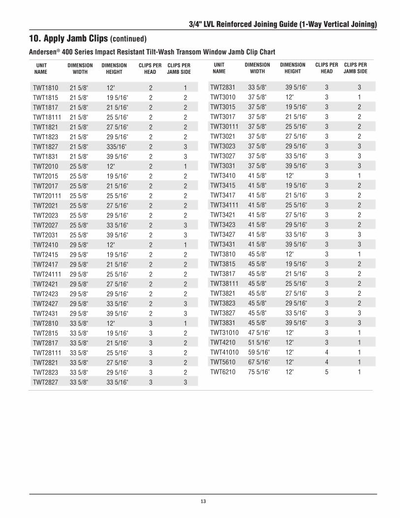
UNIT DIMENSION DIMENSION CLIPS PER CLIPS PER NAME WIDTH HEIGHT HEAD JAMB SIDE
TWT1810 21 5/8" 12" 2 1
TWT1815 21 5/8" 19 5/16" 2 2 TWT1817 21 5/8" 21 5/16" 2 2 TWT18111 21 5/8" 25 5/16" 2 2 TWT1821 21 5/8" 27 5/16" 2 2
TWT1823 21 5/8" 29 5/16" 2 2 TWT1827 21 5/8" 335/16" 2 3 TWT1831 21 5/8" 39 5/16" 2 3 TWT2010 25 5/8" 12" 2 1 TWT2015 25 5/8" 19 5/16" 2 2 TWT2017 25 5/8" 21 5/16" 2 2 TWT20111 25 5/8" 25 5/16" 2 2 TWT2021 25 5/8" 27 5/16" 2 2 TWT2023 25 5/8" 29 5/16" 2 2 TWT2027 25 5/8" 33 5/16" 2 3 TWT2031 25 5/8" 39 5/16" 2 3 TWT2410 29 5/8" 12" 2 1 TWT2415 29 5/8" 19 5/16" 2 2 TWT2417 29 5/8" 21 5/16" 2 2 TWT24111 29 5/8" 25 5/16" 2 2 TWT2421 29 5/8" 27 5/16" 2 2 TWT2423 29 5/8" 29 5/16" 2 2 TWT2427 29 5/8" 33 5/16" 2 3 TWT2431 29 5/8" 39 5/16" 2 3 TWT2810 33 5/8" 12" 3 1 TWT2815 33 5/8" 19 5/16" 3 2 TWT2817 33 5/8" 21 5/16" 3 2 TWT28111 33 5/8" 25 5/16" 3 2 TWT2821 33 5/8" 27 5/16" 3 2 TWT2823 33 5/8" 29 5/16" 3 2 TWT2827 33 5/8" 33 5/16" 3 3
Andersen® 400 Series Impact Resistant Tilt-Wash Transom Window Jamb Clip Chart
UNIT DIMENSION DIMENSION CLIPS PER CLIPS PER NAME WIDTH HEIGHT HEAD JAMB SIDE
TWT2831 33 5/8" 39 5/16" 3 3 TWT3010 37 5/8" 12" 3 1 TWT3015 37 5/8" 19 5/16" 3 2 TWT3017 37 5/8" 21 5/16" 3 2 TWT30111 37 5/8" 25 5/16" 3 2 TWT3021 37 5/8" 27 5/16" 3 2 TWT3023 37 5/8" 29 5/16" 3 3 TWT3027 37 5/8" 33 5/16" 3 3 TWT3031 37 5/8" 39 5/16" 3 3 TWT3410 41 5/8" 12" 3 1 TWT3415 41 5/8" 19 5/16" 3 2
TWT3417 41 5/8" 21 5/16" 3 2 TWT34111 41 5/8" 25 5/16" 3 2 TWT3421 41 5/8" 27 5/16" 3 2 TWT3423 41 5/8" 29 5/16" 3 2 TWT3427 41 5/8" 33 5/16" 3 3 TWT3431 41 5/8" 39 5/16" 3 3 TWT3810 45 5/8" 12" 3 1 TWT3815 45 5/8" 19 5/16" 3 2 TWT3817 45 5/8" 21 5/16" 3 2 TWT38111 45 5/8" 25 5/16" 3 2 TWT3821 45 5/8" 27 5/16" 3 2 TWT3823 45 5/8" 29 5/16" 3 2 TWT3827 45 5/8" 33 5/16" 3 3 TWT3831 45 5/8" 39 5/16" 3 3 TWT31010 47 5/16" 12" 3 1 TWT4210 51 5/16" 12" 3 1 TWT41010 59 5/16" 12" 4 1 TWT5610 67 5/16" 12" 4 1 TWT6210 75 5/16" 12" 5 1
10. Apply Jamb Clips (continued)
3/4" LVL Reinforced Joining Guide (1-Way Vertical Joining)
13

6"
Center
6"
6"
MultipleJambClipsEqually Spaced
6"MultipleJambClipsEqually Spaced
6" 6"Center
6"
Center
Center
10. Apply Jamb Clips (continued)
Picture Window Units
• Determinequantityofclipsbasedon unit size from chart on Page 15.
• PositionJamb Clips in kerf on back side of jambs, long leg to interior.
• LocateJamb Clips 6 " from each corner on head and jamb. Equally space remaining clips (if required) in between.
• LocateJamb Clips 6 " from top corner on side jambs and next to Gusset Plate. Equally space the thirdJambClip(ifrequired)inbetween.
• FastenJamb Clipsusingtwo(2)#8x 5/8" screws.
JambClip5/8" Screw
Interior Side Up
Interior View
Head
Sill
JambClip(NexttoGussetPlate)
Gusset Plate
Failure to properly anchor using jamb clips will adversely affect design pressure rating, product performance and may result in injury, product and/or property damage.
Metal fasteners and other hardware components may corrode when exposed to preservative treated and fire-retardant treated lumber. Obtain and use the appropriate metal fasteners and hardware as called out by the installation guide to fasten unit to any rough opening made from pressure treated and fire-retardant treated lumber. Failure to use the appropriate materials for the installation may cause a failure resulting in injury, property or product damage.
3/4" LVL Reinforced Joining Guide (1-Way Vertical Joining)
14

Andersen® 400 Series Tilt-Wash Impact Resistant Picture Window Jamb Clip Chart
UNIT UNIT UNIT CLIPS PER CLIPS PER NAME WIDTH HEIGHT HEAD JAMB SID
DHP31052 475/16" 6414/16" 3 4DHP31056 475/16" 6814/16" 3 4DHP310510 475/16" 7214/16" 3 5DHP31062 475/16" 7614/16" 3 5DHP42310 515/16" 4814/16" 3 3DHP4242 515/16" 5214/16" 3 4DHP4246 515/16" 5614/16" 3 4DHP42410 515/16" 6014/16" 3 4DHP4252 515/16" 6414/16" 3 4DHP4256 515/16" 6814/16" 3 4DHP42510 515/16" 7214/16" 3 5DHP4262 515/16" 7614/16" 3 5DHP410310 595/16" 4814/16" 4 3DHP41042 595/16" 5214/16" 4 4DHP41046 595/16" 5614/16" 4 4DHP410410 595/16" 6014/16" 4 4DHP41052 595/16" 6414/16" 4 4DHP41056 595/16" 6814/16" 4 4DHP410510 595/16" 7214/16" 4 5DHP41062 595/16" 7614/16" 4 5DHP56310 675/16" 4814/16" 4 3DHP5642 675/16" 5214/16" 4 4DHP5646 675/16" 5614/16" 4 4DHP56410 675/16" 6014/16" 4 4DHP5652 675/16" 6414/16" 4 4DHP5656 675/16" 6814/16" 4 4DHP56510 675/16" 7214/16" 4 5DHP5662 675/16" 7614/16" 4 5
UNIT UNIT UNIT CLIPS PER CLIPS PER NAME WIDTH HEIGHT HEAD JAMB SIDE
DHP10310 12" 4814/16" 1 3
DHP1042 12" 5214/16" 1 4DHP1046 12" 5614/16" 1 4DHP10410 12" 6014/16" 1 4DHP1052 12" 6414/16" 1 4
DHP1056 12" 6814/16" 1 4DHP10510 12" 7214/16" 1 5DHP1062 12" 7614/16" 1 5DHP30310 3710/16" 4814/16" 3 3DHP3042 3710/16" 5214/16" 3 4DHP3046 3710/16" 5614/16" 3 4DHP30410 3710/16" 6014/16" 3 4DHP3052 3710/16" 6414/16" 3 4DHP3056 3710/16" 6814/16" 3 4DHP30510 3710/16" 7214/16" 3 5DHP3062 3710/16" 7614/16" 3 5 DHP34310 4110/16" 4814/16" 3 3DHP3442 4110/16" 5214/16" 3 4DHP3446 4110/16" 5614/16" 3 4DHP34410 4110/16" 6014/16" 3 4DHP3452 4110/16" 6414/16" 3 4DHP3456 4110/16" 6814/16" 3 4DHP34510 4110/16" 7214/16" 3 5DHP3462 4110/16" 7614/16" 3 5DHP310310 475/16" 4814/16" 3 3DHP31042 475/16" 5214/16" 3 4DHP31046 475/16" 5614/16" 3 4DHP310410 475/16" 6014/16" 3 4
10. Apply Jamb Clips (continued)
3/4" LVL Reinforced Joining Guide (1-Way Vertical Joining)
15

11. Apply Jamb Clips at Gusset Plates• DeterminenumberofclipsperGusset
Plate from chart below.• ForSill Gusset Plates, Position Jamb
Clips to the side of each sill Gusset Plate, long leg to interior, extending 1-1/8" above jambs, and fasten using two(2)#8-1-1/4"screws.
• ForHead Gusset Plates, Position Jamb Clips in kerf at each head Gusset Plate, long leg to interior, extending 1-1/8" above jambs, and fasten using two(2)#8-15x5/8"screws.
Head Gusset Plate
JambClip
1"1" 1'6" 2'1" 2'6" 3'1" 3'6" 4'1" 4'6" 5'1" 5'6" 6’1
(A + B) ÷ 2 = 6' 1" 2 2 2 2 2 2 4 4 4 4 4(A + B) ÷ 2 = 5' 6" 2 2 2 2 2 2 4 4 4 4 4(A + B) ÷ 2 = 5' 1" 2 2 2 2 2 2 4 4 4 4 4(A + B) ÷ 2 = 4' 6" 2 2 2 2 2 2 4 4 4 4 4(A + B) ÷ 2 = 4' 1" 2 2 2 2 2 2 4 4 4 4 4(A + B) ÷ 2 = 3' 6" 2 2 2 2 2 2 4 4 4 4 4(A + B) ÷ 2 = 3' 1" 2 2 2 2 2 2 2 4 4 4 4(A + B) ÷ 2 = 2' 6" 2 2 2 2 2 2 2 4 4 4 4(A + B) ÷ 2 = 2' 1" 2 2 2 2 2 2 2 2 4 4 4 (A + B) ÷ 2 = 1' 6" 2 2 2 2 2 2 2 2 2 2 4 (A + B) ÷ 2 = 1' 1" 2 2 2 2 2 2 2 2 2 2 2
Aver
Age
AD
jAce
nT
Uni
T
Dim
enSi
on
C = (mullion length)
Installation Clip Application at Mull Ends (clips per end)
Two Jamb Clip Application at Head
#8x5/8"Screws
JambClips
JambClips
#8x5/8"Screws
Four Jamb Clip Application at Head
Interior Side Up
Head Gusset Plate
Head
Sill
Jamb Clip Application at Sill
#8x1-1/4"Screws
Sill Gusset Plate
3/4" LVL Reinforced Joining Guide (1-Way Vertical Joining)
16
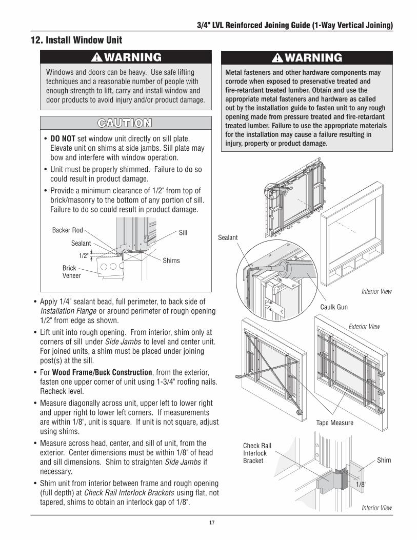
12. Install Window Unit
• DO NOT set window unit directly on sill plate. Elevate unit on shims at side jambs. Sill plate may bow and interfere with window operation.
• Unitmustbeproperlyshimmed.Failuretodosocould result in product damage.
• Provideaminimumclearanceof1/2"fromtopofbrick/masonry to the bottom of any portion of sill. Failure to do so could result in product damage.
Windows and doors can be heavy. Use safe lifting techniques and a reasonable number of people with enough strength to lift, carry and install window and door products to avoid injury and/or product damage.
Tape Measure
BrickVeneer
Sill
Shims
Sealant
Interior View• Apply1/4"sealantbead,fullperimeter,tobacksideof
Installation Flange or around perimeter of rough opening 1/2" from edge as shown.
• Liftunitintoroughopening.Frominterior,shimonlyatcorners of sill under Side Jambs to level and center unit. For joined units, a shim must be placed under joining post(s) at the sill.
• For Wood Frame/Buck Construction, from the exterior, fasten one upper corner of unit using 1-3/4" roofing nails. Recheck level.
• Measurediagonallyacrossunit,upperlefttolowerrightand upper right to lower left corners. If measurements are within 1/8", unit is square. If unit is not square, adjust using shims.
• Measureacrosshead,center,andsillofunit,fromtheexterior. Center dimensions must be within 1/8" of head and sill dimensions. Shim to straighten Side Jambs if necessary.
• Shimunitfrominteriorbetweenframeandroughopening(full depth) at Check Rail Interlock Brackets using flat, not tapered, shims to obtain an interlock gap of 1/8".
BackerRod
Interior View
1/8"
Check Rail Interlock Bracket Shim
Caulk Gun
Sealant
Exterior View
Metal fasteners and other hardware components may corrode when exposed to preservative treated and fire-retardant treated lumber. Obtain and use the appropriate metal fasteners and hardware as called out by the installation guide to fasten unit to any rough opening made from pressure treated and fire-retardant treated lumber. Failure to use the appropriate materials for the installation may cause a failure resulting in injury, property or product damage.
3/4" LVL Reinforced Joining Guide (1-Way Vertical Joining)
17

Interior View
Exterior View
12. Install Window Unit (Continued)
Outer Frame MemberBracket
#8x3"ColorMatched Screw
Wood Frame/Buck Construction
• Fastenunittowoodframeroughopeningusingtwo(2)#8x1-1/4"screwsthrougheachJamb Clip.
• SecureOuter Frame Member Brackets to rough openingusing#8x3"Color Matched Screws.
• Fastenunittomasonryroughopeningusingtwo(2)#8x1-1/4"(minimum)masonryanchorsthrougheachJamb Clip.
• Removeexisting3" Color Matched Screw and secure Outer Frame Member Bracket to rough opening using #8x3"(minimum)masonryanchor.
Masonry Construction
JambClip JambClip(bentintoposition)
Outer Frame MemberBracket
Outer Frame MemberBracket#8x3"Color
Matched Screw(provided)
#8x3"MinimumMasonry Screw(by others)
JambClip
Outer Frame MemberBracket
JambClip
#8x1-1/4"Screw
3/4" LVL Reinforced Joining Guide (1-Way Vertical Joining)
18

14. Apply Flashing Tape
• ApplyflashingtapeoverInstallation Flange at sill.• ApplyflashingtapeoverInstallation Flange at sides, overlapping flashing tape at sill.• ApplyflashingtapeoverInstallation Flange at head, overlapping flashing tape at sides.
• Thisinstructionstepdepictsoneofmanyoptionsforproperflashing.• Moistureinfiltrationproblemsinanytypeofbuildingcanbereducedbyproperlyflashingand/orsealing
around all building openings, including windows and doors. Proper flashing under and around window and door openings can reduce moisture problems, but the performance of any building system depends upon the design and construction of the building system in its entirety, which should address local environment, climate, building codes and product and material limitations. The design and installation of flashing and sealing systems are the responsibility of the architect, contractor, installer, and/or the manufacturer of the building exterior specified for the project.
Exterior View
Flashing Tape
Sill (apply first)
Sides (apply second)
Head (apply third)
13. Apply Full Width Drip Cap• Applysealantattoponly.Quicklyplacedripcap
(full width) in sealant, centering over unit(s).
DripCap(full width)
Caulk Gun
Exterior View
3/4" LVL Reinforced Joining Guide (1-Way Vertical Joining)
19

16. Insulate and Seal Unit
• Insulatebetweenframe,extensionjambs,andrough opening on all sides from the interior. DO NOT overpack or overfill with insulation, bowed jambs may result.
• Applybackerrodandsealantaroundexteriorperimeter of window after siding (or other finish) is applied.
A minimum space of 1/4" is required around exterior perimeter of unit between frame andsiding.Masonry/BrickVeneerinstallations require a minimum 1/2" space along sill and 1/4" space around the remaining perimeter.
When insulating between unit's frame and rough opening or between units when joining, DO NOT overpack batt insulation oroverfillwithfoam.Bowedjambswillresult affecting product performance and/or proper operation of unit.
Brick VeneerSiding
Exterior View
BackerRod
SealantBackerRod Sealant
Cross Section Detail -SideJamb
Cross Section Detail - Sill
15. Seal Sides• Applysealanttosideswhereinstallationflange
meets sides of units.
Exterior View
Caulk Gun
Caulk Gun
3/4" LVL Reinforced Joining Guide (1-Way Vertical Joining)
20

17. Apply Extension Jambs
RippingofExtensionJambsmayberequiredtofitnonstandard wall depths. Contact your Andersen® dealer for further information.
• Drill3/32"holes,12"-18"apart,througheachExtension Jamb on back side of kerf if Extension Jambisnotalreadypre-drilled.
• Start#8x1-1/4"drywallscrewsinholes.• PositionHead,Sill and Side Extension Jambs on
frame. Fasten center screw into each Extension Jamb using a power drill with Phillips extension.
• SquareHead, Sill, and Side Extension Jambs to unit. • FastenscrewsinExtension Jambs.• ShimbetweenExtension Jambs and rough opening.• FacenailExtension Jambs to rough opening at shims.
#8x1-1/4"Screw
Head Extension Jam
Side Extension Jamb
SillExtensionJamb
#8x1-1/2"Corner Screw
Center Screw
RippingofExtensionJambsmayberequiredtofitnonstandard wall depths. Contact your Andersen dealer for further information.
Interior Views
Interior Views
3/4" LVL Reinforced Joining Guide (1-Way Vertical Joining)
21

• DO NOT expose unfinished wood to high moisture conditions, excessive heat or humidity. Finish interior wood surfaces immediately after installation. Unfinished wood surfaces will discolor, deteriorate, and/or may bow and split.
• DO NOT stain or paint weatherstrip, silicone beads, vinyl,glass,orhardware.Damagetoproductmayoccur and unit operation may be impaired.
• Acidsolutionsusedtowashmasonry/concretewilldamage glass, fasteners, hardware, and metal flashing. If these solutions are used, follow the acid solution manufacturer's instructions carefully. Protect and/or cover Andersen products during the cleaning process to prevent acid contact. If acid does come in contact with unit, immediately wash all surfaces with clean water.
MAINTENANCEImmediately sand and refinish any interior wood thatbecomes stained or mildewed to prevent further discoloration and/or damage. For further information,contact your local Andersen dealer.Dealerscanbefound in the Yellow Pages under Windows.
Finishing, Cleaning, and Maintenance Instructions
INTERIOR FINISHING Read and follow finishing manufacturer’s instructions
and warnings on each container of finish material for priming, painting, staining, and varnishing.
CLEANING Clean exterior frame, sash members, and insect
screens using a mild detergent-and-water solution and a soft cloth or brush. DO NOT use abrasive cleaners or solutions containing corrosive solvents. For persistent dirt or grime, use a nonabrasive cleanser or a mixture of water and alcohol or ammonia.
3/4" LVL Reinforced Joining Guide (1-Way Vertical Joining)
22

3/4" LVL Reinforced Joining Guide (1-Way Horizontal Joining)
Windows and doors can be heavy. Use safe lifting techniques and a reasonable number of people with enough strength to lift, carry and install window and door products to avoid injury and/or product damage.
Impact Resistant Glass used by Andersen is not hurricane proof or shatter proof, and may not offer a high level of security. Proper installation of window and door units with impact resistant glass is as important to product performance as the glass. Every assembly and installation is different (windloads, structural support, etc.), and Andersen strongly recommends consultation with an Andersen supplier or an experienced contractor, architect, or structural engineer prior to the assembly and installation of any Andersen product. Andersen has no responsibility in regard to the post-manufactured assembly and installation of Andersen products.
Congratulations! You have just purchased one of the many fine Andersen® products. Proper assembly, installation and maintenance are essential if the benefits of your Andersen product are to be fully attained. Therefore, please read and follow this Instruction Guide completely. If your abilities do not match this procedure’s requirements, contact an experienced contractor. You may direct any questions about this or other products to your local Andersen dealer, found in the Yellow Pages under “Windows” or call Andersen WindowCare® service center at 1-888-888-7020 Monday through Friday, 7 a.m. to 7 p.m. Central Time and Saturday, 8 a.m. to 4 p.m. Central Time. Thank you for choosing Andersen.
• Andersen® Head Flashing and Installation Flanges DO NOT take the place of standard window and door flashing. Unit must be properly flashed and sealed with silicone for protection against water and air infiltration. Use non-reflective flashings. Highly reflective flashing tapes can raise the surface temperature of the vinyl to the point where vinyl deformation and product damage may occur.
• Donotapplyanytypeoffilmtoglass.Thermalstressconditionsresultinginglassdamagecouldoccur.
• Useofmovableinsulatingmaterialssuchaswindowcoverings,shutters,andothershadingdevicesmaydamageglass and/or vinyl. In addition, excessive condensation may result causing deterioration of windows and doors.
Unless specifically ordered, Andersen windows and doors are not equipped with safety glass, and if broken, could fragment causing injury. Many laws and building codes require safety glass in locations adjacent to or near doors. Andersen windows are available with safety glass that may reduce the likelihood of injury when broken. Information on safety glass is available from your local Andersen dealer.
Use caution when working at elevated heights and around unit openings. Follow manufacturer’s instructions for safe use of ladder and/or scaffolding. Failure to do so may result in injury or death.
Follow manufacturer’s instructions for safe operation of hand/power tools. Always wear safety glasses. Failure to do so may result in injury and/or product damage.
3/4" LVL Reinforced Joining Guide(1-Way Horizontal Joining)for Andersen® 400 Series Tilt-Wash Transom or Narroline® Circle Top™ Window over 400 Series Tilt-Wash Double-Hung or Tilt-Wash Picture Windows with Stormwatch® Protection
Revised 11/24/08
“Andersen” and al l other marks where denoted are trademarks of Andersen Corporation. ©2004-2007 Andersen Corporation. Al l r ights reser ved.
23

Tools and Supplies•SafetyGlasses•TapeMeasure•Pencil•Level•Hammer•Clamps•PowerDrill•CaulkGun•Sealant•ViseGrip/Pliers•ScrewDriver•UtilityKnife
Additional Parts Required•DripCap(fullwidth)
Parts Included(1) Instruction Guide(2) Gusset Plates(1)3/4"LVLJoiningStrip(1) Exterior Trim Strip(1) Installation Screw Pack(2) Gusset Plates (for Narroline® Circle Top™ Windows)(1) Head Filler Piece (for Narroline® Circle Top™ Windows)
Component Identification
Use this guide to join two units horizontally.
3/4"LVLJoiningStrip
Exterior Trim Strip
Gusset Plate
• Unitsmustbeinstalledaccordingtothefollowing installation instructions using JambClipsorproductwillnotmeetdesignated performance levels.
•DONOTapplyExtensionJambspriortounit installation.
Exterior Views
•SmallPryBar•3/8"WoodShims•PowerSaw•File/Rasp•PuttyKnife•3/32"DrillBit•IsopropylAlcohol•WoodBlocks•Shims•7/16"x1/2"x16GaugeStaples•PneumaticStapler•1-3/4"RoofingNails
Gusset Plate (for Narroline® Circle Top™ Windows)
Head Filler Piece(for Narroline® Circle Top™ Windows)
Metal fasteners and other hardware components may corrode when exposed to preservative treated and fire-retardant treated lumber. Obtain and use the appropriate metal fasteners and hardware as called out by the installation guide to fasten unit to any rough opening made from pressure treated and fire-retardant treated lumber. Failure to use the appropriate materials for the installation may cause a failure resulting in injury, property or product damage.
3/4" LVL Reinforced Joining Guide (1-Way Horizontal Joining)
24

1. Verify that LVL Joining is Adequate for Your Installation• Calculatetheaverageadjacentunitdimension((A+B)÷2).• Determinethemullionlength(C).• Usethewindloadtablebelowtocrossreferencetheaverage
adjacent unit dimension with the mullion length to determine the windload performance of your combination.
• Besurethatthisperformanceisadequateforyourinstallationrequirements.
• RefertotheCombinationDesignsectionintheAndersen ® Product Guide for Professionals for further information.
Design Windload PSF Table for 3/4" LVL Reinforced JoiningType of Combination: Horizontal JoiningFor Combining: 400 Series Double-Hung Transom Window over 400 Series Tilt-Wash Double-Hung or Picture Windows
PSF 1"1" 1'6" 2'1" 2'6" 3'1" 3'6" 4'1" 4'6" 5'1" 5'6" 6'1"
(A + B) ÷ 2 = 6' 1" 82 82 82 82 82 82 82 82 82 82 70(A + B) ÷ 2 = 5' 6" 82 82 82 82 82 82 82 82 82 82 71(A + B) ÷ 2 = 5' 1" 82 82 82 82 82 82 82 82 82 82 72(A + B) ÷ 2 = 4' 6" 82 82 82 82 82 82 82 82 82 82 75(A + B) ÷ 2 = 4' 1" 82 82 82 82 82 82 82 82 82 82 79(A + B) ÷ 2 = 3' 6" 82 82 82 82 82 82 82 82 82 82 82 (A + B) ÷ 2 = 3' 1" 82 82 82 82 82 82 82 82 82 82 82(A + B) ÷ 2 = 2' 6" 82 82 82 82 82 82 82 82 82 82 82(A + B) ÷ 2 = 2' 1" 82 82 82 82 82 82 82 82 82 82 82(A + B) ÷ 2 = 1' 6" 82 82 82 82 82 82 82 82 82 82 82(A + B) ÷ 2 = 1' 1" 82 82 82 82 82 82 82 82 82 82 82
Aver
Age
AD
jACe
NT
UNi
T
Dim
eNSi
oN
C = (mullion length)
Transom Unit
Double-HungUnit
Exterior View
3/4" LVL Reinforced Joining Guide (1-Way Horizontal Joining)
25

•Determineroughopeningheightformultipleunitsusingtheformula: rough opening height = 3/8" (shim)+total unit heights + 3/4" for each join(LVLJoiningStrip)+ 3/8" (shim).
•Determineroughopeningwidthusingtheformula:rough opening width = 3/8" (shim)+ unit width + 3/8" (shim).
•Checkroughopeningforplumbandlevel.Ifroughopeningisnot plumb or level, correct as necessary.
•Checkopeningforsquarebymeasuringdiagonally,upperleftto lower right and upper right to lower left corner. If measurements are within 1/8", opening is square. If rough opening is not square, correct as necessary.
3. Prepare Units• Placeunitsinteriorsideuponaclean,
flat work surface.• RemoveInstallation Flange(s) on head
jambofDouble-HungUnitandsillofTransom / Circle Top Unit.
• RemovebandingtapeonDouble-HungWindow.
2. Prepare Rough Opening
Exterior View
Installation Flanges(Removed)
Transom Unit
Double-HungUnit
Double-HungUnit
Transom Unit
3/4"LVLJoiningStrip
Gusset Plate
Interior Side Up
Interior Side Up
Tape Measure
Level
The use of building wrap and/or flashing materials will reduce the rough opening size. Adjust as necessary.
HeadJamb(Double-HungUnit)
Sill (Transom Unit)
Exterior View
Head
Sill
Head
Sill
3/4" LVL Reinforced Joining Guide (1-Way Horizontal Joining)
26

3. Prepare Units (Continued)• ForDouble-Hung Units, remove the end of
head jamb tenon joints that protrudes into the side jamb kerf, using a small file or rasp. Remove enough material so Gusset Plate will lie flat in kerf.
• ForPicture Window Units, remove the end of head jamb tenon joint that protrudes into the side jamb kerf, using a small file or rasp. Remove enough material so Gusset Plate will lie flat in kerf.
• ForTransom Window Units, remove the end of sill jamb tenon joint that protrudes into the side jamb kerf, using a small file or rasp. Remove enough material so Gusset Plate will lie flat in kerf.
• ForNarroline® Circle Top™, position Head Filler Piece flush with Interior Frame. Attach using 3/4" fasteners every 8"
Interior Side Up
TenonJointSideJambKerf
Side JambKerf
TenonJoint
Transom Unit
Double-HungUnit
4. Prepare 3/4" LVL Joining Strip• Squareendcut3/4" LVL Joining Strip 1/2"
shorter than width of units to be joined.• Remove1-1/2"ofaluminumlegfromeach
side at ends of 3/4" LVL Joining Strip using a vise grip/pliers.
AluminumLeg
3/4"LVLJoiningStrip
1-1/2"
5. Attach 3/4" LVL Joining Strip • Placelocatortabof3/4" LVL Joining Strip into kerf on
head jamb and center on unit. 3/4" LVL Joining Strip must not extend into side jamb kerfs.
• Fastenusingthree(3)#8x1-3/8" screws, equally spaced.
#8x1-3/8" Screw
3/4"LVLJoiningStrip
SideJambKerf
Kerf LocatorTab
Interior Side Up
Head
Sill
ViseGrip/Pliers
Head
Sill
Level
Filler Piece
Narroline® Circle-Top™ Unit
3/4" LVL Reinforced Joining Guide (1-Way Horizontal Joining)
27

6. Join Units
• Slideunitstogether,overlappingupperunitInstallation Flange over lower unit Installation Flange to the exterior. Exterior nose of units and side jambs must be flush full length.
• Clampunitstogether,fromtheinterior,usingtwoclamps with surface protectors/wood blocks.
• SlideupperandlowersashdowninTilt-WashUnitframe so Head Jamb Liner is accessible and brace with a wood block.
• RemoveHead Jamb Liner screws on Tilt-Wash unit ifpresent.Drill3/32" holes through existing holes no deeper than 2-1/2".
• IfHead Jamb Liner Screws are not present, use a 3/32" drill bit to drill pilot holes on Head Jamb Liner scribe line 4" from each end and equally spaced between as shown. See table below for total quantity of holes required.
• FastenunitstogetherthroughlowerunitHead Jamb using#10x2-1/2" screws.
• Exteriornoseofunitsandsidejambsmustbeflushfull length. Failure to do so will prevent proper sealing causing water infiltration.
• Excesstighteningofclampsmaymarsurface.• UpperunitsidejambInstallationFlangemust
overlap lower unit side Installation Flange to the exterior.
3/4"LVLJoiningStrip ClampTransom / Circle Top™ over Tilt-Wash
Installation Flange(Upper Unit)
Installation Flange(LowerUnit)
Interior Side UpHead
Sill
Unit Width Total Holes Required
TW38 & TW34 4
All Others 3
Wood Block
Interior Side Up
4"
3 or 4 Holes Equally Spaced
4"
HeadJambLinerScrew(Remove if Present)
4"
ScribeLine
#10x2-1/2" Screws(Through Pilot Holes in HeadJambLiner)
Drill
Pilot Hole
Head JambLiner
3/4" LVL Reinforced Joining Guide (1-Way Horizontal Joining)
28

6. Join Units (Continued)
• Slideunitstogether,overlappingupperunitInstallation Flange over lower unit Installation Flange to the exterior. Exterior nose of units and side jambs must be flush full width.
• InsertasmallprybarbetweenSide Jamb Liner and Interior Trim Stop, approximately 2" down from head jamb. Pry Side Jamb Liner toward exterior and insert a thin blade putty knife at bottom of Side Jamb Liner next to sill. Pry Side Jamb Liner toward the exterior and remove. Repeat procedure for opposite Side Jamb Liner.
• Insertaputtyknifebetween Head Jamb Liner and Interior Glass Stop. Twist blade of putty knife until can be grasped and removed.
• Exteriornoseofunitsandsidejambsmustbeflush full width. Failure to do so will prevent proper sealing causing water infiltration.
• Excesstighteningofclampsmaymarsurface.• UpperunitInstallationFlangemustoverlaplower
unit Installation Flange to the exterior.
Transom / Circle Top™ over Picture Window
HeadSill
Interior Side Up
SideJambLiner
PuttyKnife
HeadJambLiner
PuttyKnife
Picture Window Unit
SmallPryBar
Interior Side Up
HeadSill
Picture Window Unit
Head
Sill
Interior Side Up
Installation Flange(LowerUnit)
Installation Flange(Upper Unit)
Interior Glass Stop
3/4" LVL Reinforced Joining Guide (1-Way Horizontal Joining)
29

6. Join Units (Continued)
• Clampunitstogether,fromtheinterior,usingtwoclamps and surface protectors.
Transom/Circle Top™ over Picture Window (Continued)
Clamp
#10x2-1/2"Screw(4" from side jambs)
3/4"LVLJoiningStrip
Head
Sill
Interior Side Up
Interior
Exterior
Cross Section Detail
2-1/2" Screw
HeadJamb(Picture Unit)
HeadJambLiner
Interior Side Up
HeadSill
Picture Window Unit
DO NOTdrillholesdeeperthan2-1/2".Drillingdeeper than 2-1/2" will result in a hole through the Transom Glass Stop.
DO NOT drive screw heads deeper than flush with headjamb.Drivingscrewsdeeperthansurfaceofhead jamb may result in damage to Transom Glass Stop
• Clampunitstogether,fromtheinterior,usingtwoclamps and surface protectors.
• DrillthreeholesthroughheadjambofDouble-HungPicture Unit in the middle of void exposed when Head JambLinerwasremoved.Holesshouldbelocated4"from each side jamb and on center, midway between thesidejambs.Drillthroughtheheadjamboftheunit,through3/4"LVLJoiningStrip,andintothejamboftheTransom/CircleTopUnitusinga3/32"drillbit.DONOTdrill deeper than 2-1/2".
• Fastenunitsusing#10x2-1/2"screwsthroughdrilledholesintheDouble-HungPictureUnitheadjamb.DONOT drive/insert screws further than flush with the head jamb.
• ReinstallHead Jamb Liner by inserting long leg of liner into head pocket, pushing up on short leg to snap into place.
• InsertinteriorlegofSide Jamb Liner behind Interior Trim Stop, pushing in on exterior leg to snap into place. Repeat for opposite side.
LongLeg
3/4" LVL Reinforced Joining Guide (1-Way Horizontal Joining)
30

7. Attach Gusset Plates• PositionGusset Plate in jamb kerf centered over unit
joinandfastenusing#8x5/8"Screws.Gusset Plate
Gusset Plate
JambKerf
#8x5/8"Screws
1/2" Staples
Interior Side Up
Interior Side Up
Head
Head
Sill
Sill
• PlaceGusset Plates on side jambs 3/4" down from interior edge and in center of joint.
• Securewithtworowsof1/2"staples.
Narroline® Circle Top™ over Tilt-Wash or Picture Window
Narroline® Circle Top™
3/4" LVL Reinforced Joining Guide (1-Way Horizontal Joining)
31

8. Apply Exterior Trim Strip• Turnunitassemblyexteriorsideup.• CleansurfaceofTrim Strip Receiver and vinyl surface
of unit for proper adhesion using isopropyl alcohol.• Applyacontinuous1/8"beadofsealantalongjoinsof
Trim Strip Receivers and jambs.
• PositionedgeofExterior Trim Strip flush with unit edge and press in with thumbs from one end to the other. Pound in place using a hammer and wood block.
•ApplysealanttovoidsatbothendsofExteriorTrimStrip. Completely fill void between units on exterior side of Installation Flange.
• Turnunitassemblyinteriorsideup.• Applysealanttovoidbetweenunitsoninteriorsideof
Installation Flange for 1/2" on both sides.
Initial positioning of Exterior Trim Strip is important because it is very difficult to remove once inserted.
Exterior Side Up
Exterior Trim Strip Caulk Gun
Sealant
Caulk Gun
Sealant
Apply sealant behind Installation Flange for 1/2” on both sides.
Trim Strip Receiver
3/4" LVL Reinforced Joining Guide (1-Way Horizontal Joining)
32

9. Apply Jamb Clips
• PositionJamb Clips in kerf on back side of jambs, long leg to interior, extending 1-1/8" above jambs, as shown.
TW18 (1'-9 5/8") - TW210 Units (2'-11 5/8")
• LocatefourJamb Clips on side jambs; 1" above Check Rail Interlock Bracket, 1" below Check Rail Interlock Bracket, 8" from bottom, and next to Gusset Plate.
• LocatetwoJamb Clips on sill 8" from each side.• FastenJamb Clips to sill and side jambs using two (2)
#8x5/8"screws.
8"
Check Rail InterlockBracket
JambClip
8"
1"
1"
8" 8"
Double-Hung Units
JambClip(Next to Gusset Plate) JambClip(Next
to Gusset Plate)
1"
1"
Transom Unit (JambClipsApplied on Page 12)
Interior Side Up
Interior View
Head
Sill
JambClip(Standard)
Or6"JambClip
Extension Jamb
#8x5/8"Screw
Kerf
TW18 - TW210 Units
Failure to properly anchor using jamb clips will adversely affect design pressure rating, product performance and may result in injury, product and/or property damage.
3/4" LVL Reinforced Joining Guide (1-Way Horizontal Joining)
33

Interior Side Up
9. Apply Jamb Clips (continued)
Picture Window Units JambClip
#8x5/8"Screw
• DeterminequantityofJamb Clips based on unit size from chart on Page 35.
• PositionJamb Clips in kerf on back side of jambs, long leg to interior.
• LocateJamb Clips6 " from each corner on head and jamb. Equally space remaining clips (if required) in between.
• LocateJamb Clips6 " from top corner on side jambs and next to Gusset Plate. Equally space the additionalJambClip(ifrequired)inbetween.
• FastenJamb Clipsusingtwo(2)#8x5/8"screws.
Transom Unit (JambClipsApplied on Page 12)
6"6"
6" Equal
JambClip(Next to Gusset Plate)
EqualEqual
EqualEqual
EqualEqual
6"6"
Equal 6"Interior View
TW30 (3'-1 5/8") - TW38 Units (3'-9 5/8")
• LocatefourJamb Clips on side jambs; 1" above Check Rail Interlock Bracket, 1" below Check Rail Interlock Bracket, 8" from bottom, and next to Gusset Plate.
• LocatethreeJamb Clips on sill 8" from each side and one at center.
• FastenJamb Clips to sill and side jambs using two (2)#8x5/8"screws.
8"
1"1"
Check Rail InterlockBracket
JambClip
TW30 - TW38 Units
8"
1"1"
8" 8"
JambClip(Next to Gusset Plate)
Interior View
Transom Unit (JambClipsApplied on Page 12)
Failure to properly anchor using jamb clips will adversely affect design pressure rating, product performance and may result in injury, product and/or property damage.
3/4" LVL Reinforced Joining Guide (1-Way Horizontal Joining)
34

Andersen® 400 Series Tilt-Wash Double-Hung Picture Window Jamb Clip Chart
UNIT UNIT UNIT CLIPS PER CLIPS PER NAME WIDTH HEIGHT HEAD JAMB SIDE
DHP31052 475/16" 6414/16" 3 4DHP31056 475/16" 6814/16" 3 4DHP310510 475/16" 7214/16" 3 5DHP31062 475/16" 7614/16" 3 5DHP42310 515/16" 4814/16" 3 3DHP4242 515/16" 5214/16" 3 4DHP4246 515/16" 5614/16" 3 4DHP42410 515/16" 6014/16" 3 4DHP4252 515/16" 6414/16" 3 4DHP4256 515/16" 6814/16" 3 4DHP42510 515/16" 7214/16" 3 5DHP4262 515/16" 7614/16" 3 5DHP410310 595/16" 4814/16" 4 3DHP41042 595/16" 5214/16" 4 4DHP41046 595/16" 5614/16" 4 4DHP410410 595/16" 6014/16" 4 4DHP41052 595/16" 6414/16" 4 4DHP41056 595/16" 6814/16" 4 4DHP410510 595/16" 7214/16" 4 5DHP41062 595/16" 7614/16" 4 5DHP56310 675/16" 4814/16" 4 3DHP5642 675/16" 5214/16" 4 4DHP5646 675/16" 5614/16" 4 4DHP56410 675/16" 6014/16" 4 4
DHP5652 675/16" 6414/16" 4 4DHP5656 675/16" 6814/16" 4 4DHP56510 675/16" 7214/16" 4 5DHP5662 675/16" 7614/16" 4 5
UNIT UNIT UNIT CLIPS PER CLIPS PER NAME WIDTH HEIGHT HEAD JAMB SIDE
DHP10310 12" 4814/16" 1 3
DHP1042 12" 5214/16" 1 4DHP1046 12" 5614/16" 1 4DHP10410 12" 6014/16" 1 4DHP1052 12" 6414/16" 1 4
DHP1056 12" 6814/16" 1 4DHP10510 12" 7214/16" 1 5DHP1062 12" 7614/16" 1 5DHP30310 3710/16" 4814/16" 3 3DHP3042 3710/16" 5214/16" 3 4DHP3046 3710/16" 5614/16" 3 4DHP30410 3710/16" 6014/16" 3 4DHP3052 3710/16" 6414/16" 3 4DHP3056 3710/16" 6814/16" 3 4DHP30510 3710/16" 7214/16" 3 5DHP3062 3710/16" 7614/16" 3 5 DHP34310 4110/16" 4814/16" 3 3DHP3442 4110/16" 5214/16" 3 4DHP3446 4110/16" 5614/16" 3 4DHP34410 4110/16" 6014/16" 3 4DHP3452 4110/16" 6414/16" 3 4DHP3456 4110/16" 6814/16" 3 4DHP34510 4110/16" 7214/16" 3 5DHP3462 4110/16" 7614/16" 3 5DHP310310 475/16" 4814/16" 3 3DHP31042 475/16" 5214/16" 3 4DHP31046 475/16" 5614/16" 3 4DHP310410 475/16" 6014/16" 3 4
9. Apply Jamb Clips (continued)
3/4" LVL Reinforced Joining Guide (1-Way Horizontal Joining)
35

9. Apply Jamb Clips (continued)
Interior Side Up• DeterminequantityofJamb Clips based on unit size
from chart on Page 37.• PositionJamb Clips in kerf on back side of jambs, long
leg to interior.• LocateJamb Clips6 " from each corner on head and
jamb. Equally space remaining clips (if required) in between.
• LocateJamb Clips6 " from top corner on side jambs and next to Gusset Plate. Equally space the additional JambClip(ifrequired)inbetween.
• FastenJamb Clipsusingtwo(2)#8x5/8"screws.
Multiple Clips Equally Spaced
6"
Transom Units
JambClip
5/8" Screw
6"
6"
6"
6"6"
Transom Unit
Double-HungUnit
Interior View
Head
Sill
Failure to properly anchor using jamb clips will adversely affect design pressure rating, product performance and may result in injury, product and/or property damage.
3/4" LVL Reinforced Joining Guide (1-Way Horizontal Joining)
36

UNIT DIMENSION DIMENSION CLIPS PER CLIPS PER NAME WIDTH HEIGHT HEAD JAMB SIDE
TWT1810 21 5/8" 12" 2 1
TWT1815 215/8" 195/16" 2 2TWT1817 215/8" 215/16" 2 2TWT18111 215/8" 255/16" 2 2TWT1821 215/8" 275/16" 2 2
TWT1823 215/8" 295/16" 2 2TWT1827 215/8" 335/16" 2 3TWT1831 215/8" 395/16" 2 3TWT2010 25 5/8" 12" 2 1 TWT2015 255/8" 195/16" 2 2TWT2017 255/8" 215/16" 2 2TWT20111 255/8" 255/16" 2 2TWT2021 255/8" 275/16" 2 2TWT2023 255/8" 295/16" 2 2TWT2027 255/8" 335/16" 2 3TWT2031 255/8" 395/16" 2 3TWT2410 29 5/8" 12" 2 1 TWT2415 295/8" 195/16" 2 2TWT2417 295/8" 215/16" 2 2TWT24111 295/8" 255/16" 2 2TWT2421 295/8" 275/16" 2 2TWT2423 295/8" 295/16" 2 2TWT2427 295/8" 335/16" 2 3TWT2431 295/8" 395/16" 2 3TWT2810 33 5/8" 12" 3 1 TWT2815 335/8" 195/16" 3 2TWT2817 335/8" 215/16" 3 2TWT28111 335/8" 255/16" 3 2TWT2821 335/8" 275/16" 3 2TWT2823 335/8" 295/16" 3 2TWT2827 335/8" 335/16" 3 3
Andersen® 400 Series Tilt-Wash Transom Window Jamb Clip Chart
UNIT DIMENSION DIMENSION CLIPS PER CLIPS PER NAME WIDTH HEIGHT HEAD JAMB SIDE
TWT2831 335/8" 395/16" 3 3TWT3010 37 5/8" 12" 3 1 TWT3015 375/8" 195/16" 3 2TWT3017 375/8" 215/16" 3 2TWT30111 375/8" 255/16" 3 2TWT3021 375/8" 275/16" 3 2TWT3023 375/8" 295/16" 3 3TWT3027 375/8" 335/16" 3 3TWT3031 375/8" 395/16" 3 3TWT3410 41 5/8" 12" 3 1 TWT3415 415/8" 195/16" 3 2
TWT3417 415/8" 215/16" 3 2TWT34111 415/8" 255/16" 3 2TWT3421 415/8" 275/16" 3 2TWT3423 415/8" 295/16" 3 2TWT3427 415/8" 335/16" 3 3TWT3431 415/8" 395/16" 3 3TWT3810 45 5/8" 12" 3 1 TWT3815 455/8" 195/16" 3 2TWT3817 455/8" 215/16" 3 2TWT38111 455/8" 255/16" 3 2TWT3821 455/8" 275/16" 3 2TWT3823 455/8" 295/16" 3 2TWT3827 455/8" 335/16" 3 3TWT3831 455/8" 395/16" 3 3TWT31010 475/16" 12" 3 1TWT4210 515/16" 12" 3 1TWT41010 595/16" 12" 4 1TWT5610 675/16" 12" 4 1TWT6210 755/16" 12" 5 1
9. Apply Jamb Clips (continued)
3/4" LVL Reinforced Joining Guide (1-Way Horizontal Joining)
37

#8x1"Screw
Short JambClip
UNIT DIM. DIM. CLIPS PER CLIPS PER CLIPS PER DES. WIDTH HEIGHT ARCH SILL UNIT
CTN20 255/8" 153/16" 3 2 5CTN24 295/8" 173/16" 3 2 5CTN28 335/8" 193/16" 3 2 5CTN30 375/8" 213/16" 3 2 5CTN34 415/8" 233/16" 4 3 7CTN28-2 675/16" 36" 5 3 8CTN30-2 755/16" 40" 5 3 8
Circle Top™ Unit Dimensions & Jamb Clip Chart
• ForshortJamb Clips, flatten leg as shown.• SeeTablebelowforJamb Clip quantity based on unit size.• ForLineal Jamb, position Jamb Clips evenly along lineal
portionofunit,asshown.Spaceamaximumof6"fromany corner and approximately 30" on center.
• ForArched Jamb, space Jamb Clips evenly around arch portion of unit, approximately 25" on center, as shown. Spaceamaximumof6"fromanycorner,ifpresent.
• PositionJamb Clips as shown; Place short jamb clips in kerf on back side of jamb, long leg to the interior and extending 1-1/8” above jambs. Position long jamb clips 5-3/8” above jambs.
• FastenJamb Clips to unit using two (2) #8 x 1" Screws.
LegJambClip
30" max.6"max.
6"max.
25" max.
ShortJambClip
Leg
1-1/8"
Circle Top™ Windows
Exterior View
Interior Side Up or
#8x1"Screw
5-3/8"
LongJambClip
Failure to properly anchor using jamb clips will adversely affect design pressure rating, product performance and may result in injury, product and/or property damage.
9. Apply Jamb Clips (continued)
3/4" LVL Reinforced Joining Guide (1-Way Horizontal Joining)
38
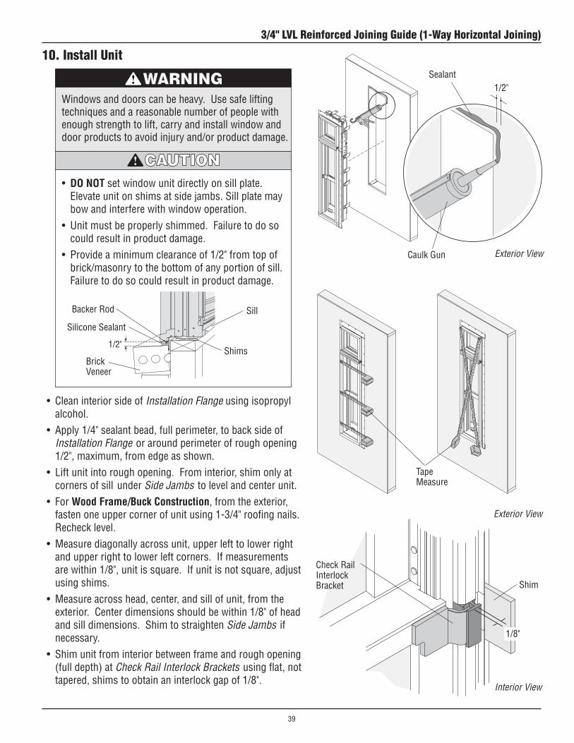
10. Install Unit
• DO NOT set window unit directly on sill plate. Elevate unit on shims at side jambs. Sill plate may bow and interfere with window operation.
• Unitmustbeproperlyshimmed.Failuretodosocould result in product damage.
• Provideaminimumclearanceof1/2"fromtopofbrick/masonry to the bottom of any portion of sill. Failure to do so could result in product damage.
Windows and doors can be heavy. Use safe lifting techniques and a reasonable number of people with enough strength to lift, carry and install window and door products to avoid injury and/or product damage.
BrickVeneer
Sill
Shims
Silicone Sealant
Exterior View
• CleaninteriorsideofInstallation Flange using isopropyl alcohol.
• Apply1/4"sealantbead,fullperimeter,tobacksideofInstallation Flange or around perimeter of rough opening 1/2", maximum, from edge as shown.
• Liftunitintoroughopening.Frominterior,shimonlyatcorners of sill under Side Jambs to level and center unit.
• For Wood Frame/Buck Construction, from the exterior, fasten one upper corner of unit using 1-3/4" roofing nails. Recheck level.
• Measurediagonallyacrossunit,upperlefttolowerrightand upper right to lower left corners. If measurements are within 1/8", unit is square. If unit is not square, adjust using shims.
• Measureacrosshead,center,andsillofunit,fromtheexterior. Center dimensions should be within 1/8" of head and sill dimensions. Shim to straighten Side Jambs if necessary.
• Shimunitfrominteriorbetweenframeandroughopening(full depth) at Check Rail Interlock Brackets using flat, not tapered, shims to obtain an interlock gap of 1/8".
BackerRod
Interior View
1/8"
Check Rail Interlock Bracket Shim
Exterior View
Tape Measure
1/2"Sealant
Caulk Gun
3/4" LVL Reinforced Joining Guide (1-Way Horizontal Joining)
39

Interior View
Exterior View
10. Install Window Unit (Continued)
OuterFrameMemberBracket
#8x3"ColorMatched Screw
Wood Frame/Buck Construction
• Fastenunittowoodframeroughopeningusingtwo(2)#8x1-1/4"screwsthrougheachJamb Clip.
• SecureOuter Frame Member Brackets to rough openingusing#8x3"Color Matched Screws.
• Drillholesintomasonryusingappropriatesizemasonry bit.
• Fastenunittomasonryroughopeningusingtwo(2)#8x1-1/4"(minimum)masonryanchorsthrougheachJamb Clip.
• Removeexisting3" Color Matched Screw and secure Outer Frame Member Bracket to rough opening using #8x3"(minimum)masonryanchor.
Masonry Construction
JambClip JambClip(bentintoposition)
Outer Frame MemberBracket
Outer Frame MemberBracket#8x3"ColorMatched
Screw (provided)
#8x3"MinimumMasonryScrew (by others)
JambClip
Outer Frame MemberBracket
JambClip
1-1/4" Screw
Masonry Screw
Wood Frame/Buck Construction
Wood Frame/Buck Construction Masonry Construction
Metal fasteners and other hardware components may corrode when exposed to preservative treated and fire-retardant treated lumber. Obtain and use the appropriate metal fasteners and hardware as called out by the installation guide to fasten unit to any rough opening made from pressure treated and fire-retardant treated lumber. Failure to use the appropriate materials for the installation may cause a failure resulting in injury, property or product damage.
3/4" LVL Reinforced Joining Guide (1-Way Horizontal Joining)
40

13. Apply Flashing Tape
• ApplyflashingtapeoverInstallation Flange at sill.• ApplyflashingtapeoverInstallation Flange at sides,
overlapping flashing tape at sill.• ApplyflashingtapeoverInstallation Flange at head,
overlapping flashing tape at sides.
• Thisinstructionstepdepictsoneofmanyoptionsfor proper flashing.
• Moistureinfiltrationproblemsinanytypeofbuilding can be reduced by properly flashing and/or sealing around all building openings, including windows and doors. Proper flashing under and around window and door openings can reduce moisture problems, but the performance of any building system depends upon the design and construction of the building system in its entirety, which should address local environment, climate, building codes and product and material limitations. The design and installation of flashing and sealing systems are the responsibility of the architect, contractor, installer, and/or the manufacturer of the building exterior specified for the project.
Unit must be properly flashed and sealed for protection against water and air infiltration. Use non-reflective flashings. Highly reflective flashing tapes can raise the surface temperature of the vinyl to the point where vinyl deformation and product damage may occur.
Exterior View
Flashing Tape
Sill (apply first)
Sides(apply second)
Head (apply third)
3/4" LVL Reinforced Joining Guide (1-Way Horizontal Joining)
41

14. Insulate and Seal Unit
• Insulatebetweenframe,extensionjambs,androughopening on all sides from the interior. DO NOT overpack or overfill with insulation, bowed jambs may result.
• Applybackerrodandsealantaroundexteriorperimeterof window after siding (or other finish) is applied.
A minimum space of 1/4" is required around exterior perimeter of unit between frame and siding.Masonry/BrickVeneerinstallationsrequireaminimum 1/2" space along sill and 1/4" space around the remaining perimeter.
When insulating between unit's frame and rough opening or between units when joining, DO NOT overpack batt insulation or overfill with foam. Bowedjambswillresultaffectingproductperformance and/or proper operation of unit.
Brick VeneerSiding
Exterior View
BackerRod
Sealant
BackerRod
Sealant
Cross Section Detail -SideJamb
Cross Section Detail - Sill
Caulk Gun
3/4" LVL Reinforced Joining Guide (1-Way Horizontal Joining)
42

15. Apply Extension Jambs
RippingofExtensionJambsmayberequiredtofitnonstandard wall depths. Contact your Andersen® dealer for further information.
• Drill3/32"holes,12"-18"apart,alongeachExtension Jamb on back side of kerf, if not predrilled.
• Start#8x1-1/4"drywallscrewsinholes.• PositionHead, Sill and Side Extension Jambs on
frame. Fasten center screw into each Extension Jamb using a power drill with Phillips extension.
• Fastencornersusing#8x1-1/2"drywallscrews.• FastenremainingscrewsinExtension Jambs.• ShimbetweenExtension Jambs and rough opening.• FacenailExtension Jambs to rough opening at shims.
#8x1-1/4"Screw
Head Extension Jamb
Side Extension Jamb
SillExtensionJamb
#8x1-1/2"Corner Screw
Center Screw
Interior Views
Interior Views
Interior Views
3/4" LVL Reinforced Joining Guide (1-Way Horizontal Joining)
43
• DO NOT expose unfinished wood to high moisture conditions, excessive heat or humidity. Finish interior wood surfaces immediately after installation. Unfinished wood surfaces will discolor, deteriorate, and/or may bow and split.
• DO NOT stain or paint weatherstrip, silicone beads, vinyl,glass,orhardware.Damagetoproductmayoccur and unit operation may be impaired.
• Acidsolutionsusedtowashmasonry/concretewilldamage glass, fasteners, hardware, and metal flashing. If these solutions are used, follow the acid solution manufacturer's instructions carefully. Protect and/or cover Andersen products during the cleaning process to prevent acid contact. If acid does come in contact with unit, immediately wash all surfaces with clean water.
MAINTENANCEImmediately sand and refinish any interior wood thatbecomes stained or mildewed to prevent further discoloration and/or damage. For further information,contact your local Andersen dealer.Dealerscanbefound in the Yellow Pages under Windows.
Finishing, Cleaning, and Maintenance Instructions
INTERIOR FINISHING Read and follow finishing manufacturer’s instructions
and warnings on each container of finish material for priming, painting, staining, and varnishing.
CLEANING Clean exterior frame, sash members, and insect
screens using a mild detergent-and-water solution and a soft cloth or brush. DO NOT use abrasive cleaners or solutions containing corrosive solvents. For persistent dirt or grime, use a nonabrasive cleanser or a mixture of water and alcohol or ammonia.
3/4" LVL Reinforced Joining Guide (1-Way Horizontal Joining)
44