3/31/2020usf physics 1011 physics 101 ac circuits
Post on 22-Dec-2015
229 views
TRANSCRIPT

3/31/2020 USF Physics 101 1
Physics 101
AC Circuits

3/31/2020 USF Physics 101 2
Agenda• Administrative matters
– EVB is still ill– Homework due today?
• AC Circuits– AC in R, L, C
• Phase Shifts• Filters
– Series LCR Circuit• Phasors
– Parallel LCR Circuit– Resonance

3/31/2020 USF Physics 101 3
AC Circuits
0( ) sin i.e. At 0, 0 and 0I t I t t I
Note that I could just as well use cos with a different ’ = + 90° or 2 rad.
sin lags cos by 90°
0 0 2 2
RMS RMS
V IV I
We will assume a sinusoidal voltage source which supplies a current
0 sin( )V V t

3/31/2020 USF Physics 101 4
R only:
Loop rule: 0V IR
0 0sin sinV I R t V t
I and V are in phase
Energy is transformed onto heat
22 RMS
RMS RMS RMS
VP IV I V I R
R

3/31/2020 USF Physics 101 5
L Only:
0
Loop rule: 0
and sin
dI dIV L V L
dt dtI I t
0 0cos cosdI
V L LI t V tdt
0
Identity: cos sin 2
so sin 90V V t
In an inductor the current lags the voltage in phase by 90°.
Alternatively, the voltage leads the current by 90°.
cos sin 0 0 0t t dt IV dt P On the average, no energy is transformed into heat

3/31/2020 USF Physics 101 6
Flow of charge impeded by back EMF as energy is stored in L
In analogy to Ohm’s Law
RMS RMS LV I X
= LX L The inductive reactance
Units:
Notes: V0 and I0 are peak values. Can also write
0 0 LV I X
V and I do not peak at the same time so V ≠ I XL at a particular time. For a resistor V = IR t.
XL = 0 for DC ( = 0)
(End of previous)
3/31/2020 USF Physics 101 7
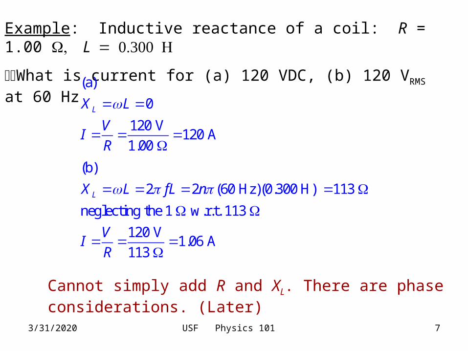
Example: Inductive reactance of a coil: R = 1.00 L
What is current for (a) 120 VDC, (b) 120 VRMS at 60 Hz
(a)
0
120 V120 A
1.00
LX L
VI
R
(b)
2 2 (60 Hz)(0.300 H) 113
neglecting the 1 w.r.t. 113
120 V1.06 A
113
LX L fL n
VI
R
Cannot simply add R and XL. There are phase considerations. (Later)
3/31/2020 USF Physics 101 8
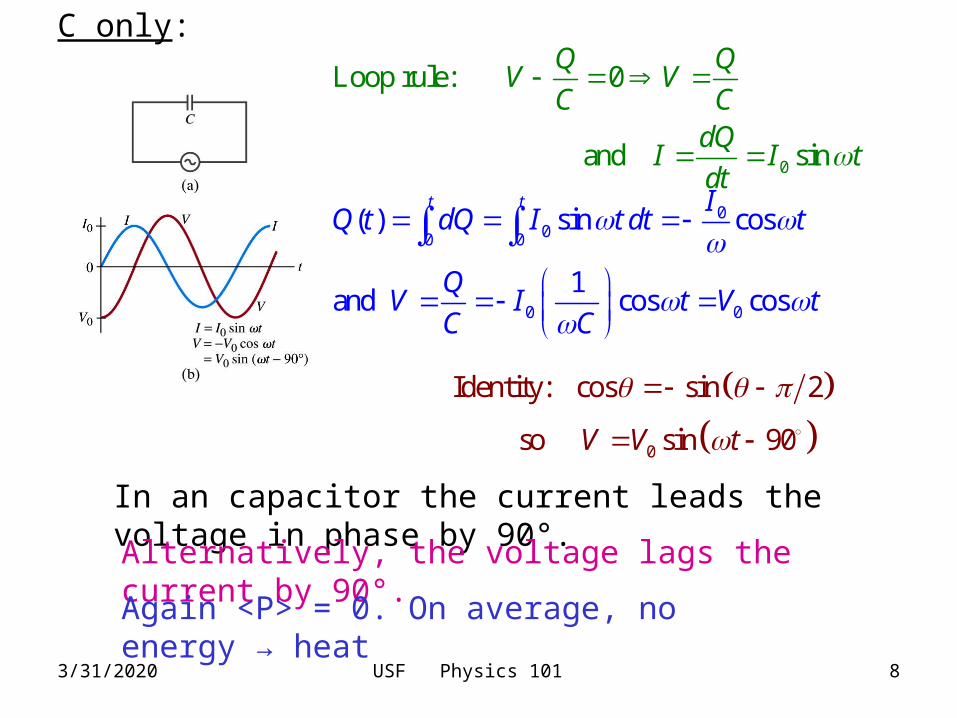
C only:
0
Loop rule: 0
and sin
Q QV V
C CdQ
I I tdt
000 0
0 0
( ) sin cos
1and cos cos
t t IQ t dQ I t dt t
QV I t V t
C C
0
Identity: cos sin 2
so sin 90V V t
In an capacitor the current leads the voltage in phase by 90°.
Alternatively, the voltage lags the current by 90°.
Again <P> = 0. On average, no energy → heat

3/31/2020 USF Physics 101 9
Flow of charge impeded by back EMF as energy is stored in C
In analogy to Ohm’s Law
1= CX
CThe capacitive reactance
0 0 CV I X
RMS RMS CV I XUnits:
Notes: V0 and I0 are peak values. Can also write
V and I are not in phase so V ≠ I XL at a particular time.
XC = for DC ( = 0)

3/31/2020 USF Physics 101 10
Example: Peak and RMS currents in C = 1.0 F, VRMS = 120 V for (a) f = 60 Hz and (b) 600 Khz
6
0
00 3
3
1 1 1(a) 2.7 k
2 2 60 Hz 1.0 10 F
2 2 120 V 170 V
170 V .063 A or 63 mA
2.7 10
120 V 44 mA
2.7 10
C
RMS
C
RMSRMS
C
XC fC
V V
VI
X
VI
X
5 6
00
1 1 1(b) 0.27
2 2 6.0 10 Hz 1.0 10 F
170 V 120 V 630 A 440 A
0.27 0.27
C
RMSRMS
C C
XC fC
V VI I
X X

3/31/2020 USF Physics 101 11
Filters:
High pass
Low pass
Replace Cs with Ls

3/31/2020 USF Physics 101 12
Series LCR Circuit:
D
At any time t, loop rule R L CV V V V
Continuity currents same in all elements at any time t
Consequence: 0 0 0 0 and RMS RMS RMSR L C RMS R L CV V V V V V V V
0 sinI I t everywhere in the series circuit. Because of their phase differences, the voltages add in a more complicated fashion.
2 Approaches: Complex variables
Graphical analysis, phasors

3/31/2020 USF Physics 101 13
Phasors: Represent voltages as vectors in a plane
0 sinI I t
t = 0
Length of each arrow = peak V gives phase w.r.t. I
Let this diagram rotate, angular velocity
0 sinRV I R t
0 sin2L LV I X t
0 sin2L CV I X t

3/31/2020 USF Physics 101 14
The vector sum of these voltages is the voltage across the whole circuit.
0 sinV V t
Source V is out of phase with I by
Define impedance, Z
0 0 or RMS RMSV I Z V I Z
Pythagoras
2 22 2 20 0 0 0 0 0 0
22 20 0 0
R L C L C
L C
V V V V I R I X I X
I R I X I X

3/31/2020 USF Physics 101 15
Phase angle 00 0
0 0
0
0
tan
or cos
L CL C L C
R
R
I X XV V X X
V I R R
V R
V Z
Power dissipated 2
cosRMSP I R
R Z
2 2 cos cosRMS RMS RMS RMSP I R I Z I V
cos is called the power factor
R alone: = 0, cos = 1
L or C alone: = ± 90°, cos = 0, no power dissipated

3/31/2020 USF Physics 101 16
Example: In series, R = 25.0 , L = 30 mH and C = 12.0 F. Driven by 90.0 VRMS at 500 Hz. (a) current in circuit, (b) voltmeter (RMS) reading across each element, (c) phase angle and (d) power dissipated.
6
2 2 22
2 2 500 Hz 0.0300 H = 94.2
1 1 126.5
2 2 500 Hz 12.0 10 F
25.0 94.2 26.5 72.2
L
C
L C
X L fL
XC fC
Z R X X
90.0 V(a) = = 1.25 A
72.2 RMS
RMS
VI
Z
3/31/2020 USF Physics 101 17
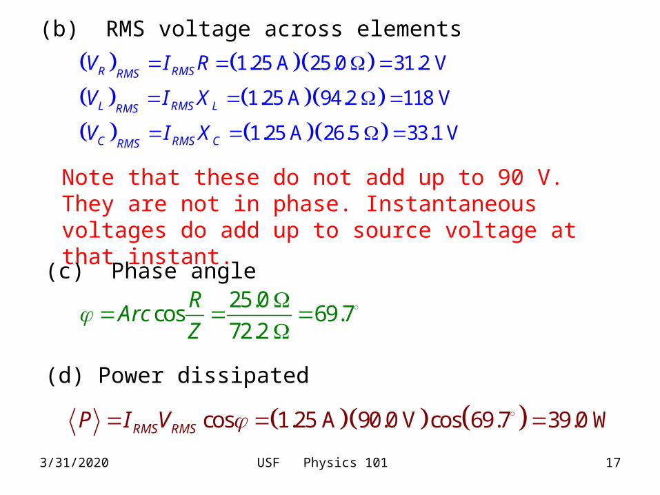
(b) RMS voltage across elements
1.25 A 25.0 31.2 V
1.25 A 94.2 118 V
1.25 A 26.5 33.1 V
R RMSRMS
L RMS LRMS
C RMS CRMS
V I R
V I X
V I X
Note that these do not add up to 90 V. They are not in phase. Instantaneous voltages do add up to source voltage at that instant.
(c) Phase angle25.0
cos 69.772.2
RArc
Z
(d) Power dissipated
cos 1.25 A 90.0 V cos 69.7 39.0 WRMS RMSP I V

3/31/2020 USF Physics 101 18
Parallel LCR Circuit 0 00
00
0 00 01
LL
R
CC
V VI
X L
VI
RV V
I V LX C
Phases differ by 90°
Here the voltage across each element is just the source voltage at any time t with no phase differences.
, , or 0 sinL R CV V t
The currents are not in phase but must obey the node rule at any point in time to preserve continuity.

3/31/2020 USF Physics 101 19
IR0
IC0
IL0
t
IL0 – IC0
IR0 I0
Pythagorean Theorem
220 0 0 0R L CI I I I
220 0 02
2
0 2
1 1 1
L C
L C
V V V
R X X
VR X X
3/31/2020 USF Physics 101 20
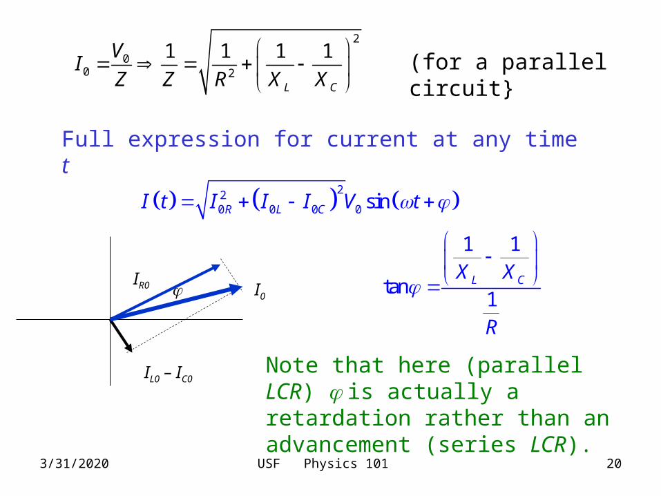
2
00 2
1 1 1 1
L C
VI
Z Z R X X
(for a parallel circuit}
Full expression for current at any time t
220 0 0 0 sinR L CI t I I I V t
IL0 – IC0
IR0 I0
1 1
tan1
L CX X
R
Note that here (parallel LCR) is actually a retardation rather than an advancement (series LCR).
3/31/2020 USF Physics 101 21
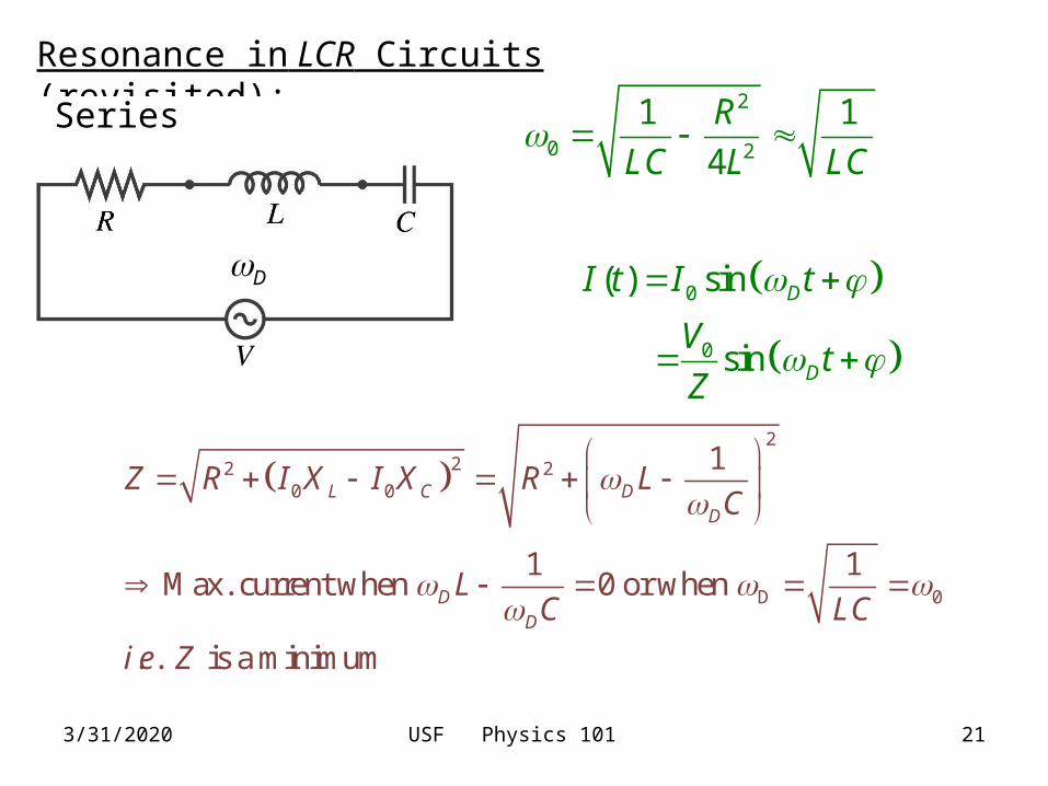
Resonance in LCR Circuits (revisited):
0
0
( ) sin
sin
D
D
I t I t
Vt
Z
D
Series 2
0 2
1 1
4
R
LC L LC
2
22 20 0
D 0
1
1 1Max. current when 0 or when
. . is a minimum
L C DD
DD
Z R I X I X R LC
LC LC
i e Z
3/31/2020 USF Physics 101 22
0
0
( ) sin
sin
D
D
I t I t
Vt
Z
D
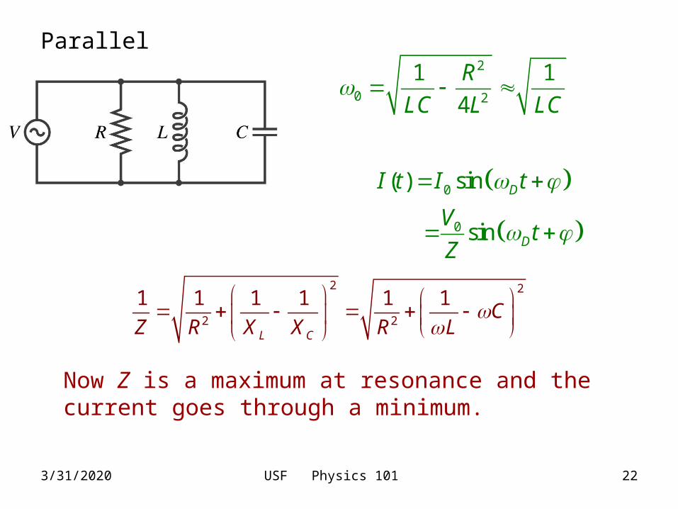
Parallel 2
0 2
1 1
4
R
LC L LC
2 2
2 2
1 1 1 1 1 1
L C
CZ R X X R L
Parallel
Now Z is a maximum at resonance and the current goes through a minimum.
3/31/2020 USF Physics 101 23
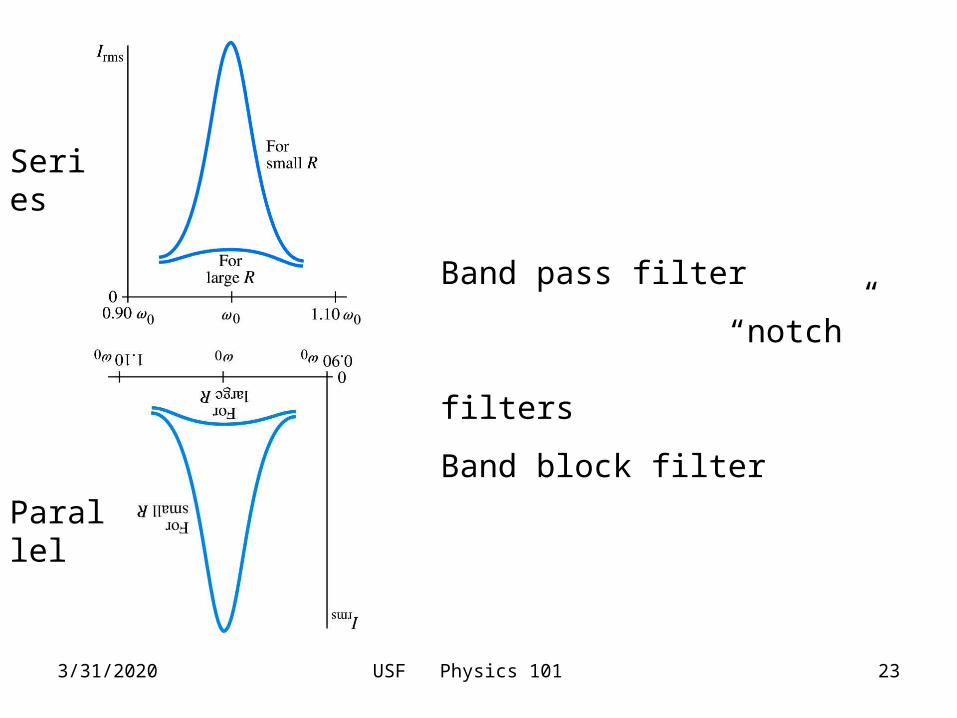
Series
Parallel
Band pass filter
“notch” filters
Band block filter
3/31/2020 USF Physics 101 24
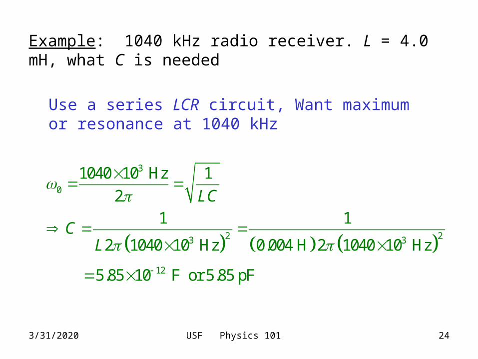
Example: 1040 kHz radio receiver. L = 4.0 mH, what C is needed
Use a series LCR circuit, Want maximum or resonance at 1040 kHz
3
0
2 23 3
12
1040 10 Hz 1
21 1
2 1040 10 Hz 0.004 H 2 1040 10 Hz
5.85 10 F or 5.85 pF
LC
CL