3300 4400 - woodmaster · 4 woodmaster owner’s manual july 2016 woody woodmaster best burn...
TRANSCRIPT
7994-500
Owner’s Manual
Northwest Manufacturing, Inc.600 Polk Ave SW
Red Lake Falls, MN 56750Retain this manual/Conserver ce manuel
COMMERCIAL USE ONLY
33004400 Heavy Duty
5500 Super Duty
6500 Super Duty
Installation, Operation& Maintenance Manual
Models:
www.woodmaster.com

Dear Customer,
We at Northwest Mfg., Inc. would like to thank you for purchasing the
WoodMaster heating system.
It is our goal to build the highest quality product at a competitive price,
and maintain total customer satisfaction.
This manual is a guide for installing, operating, and maintaining your
new WoodMaster.
Follow and observe all safety and warning instructions.
The Staff,
WoodMaster Furnaces
Web: www.woodmaster.com
3Woodmaster Owner’s ManualJuly 2016
Woody Woodmaster
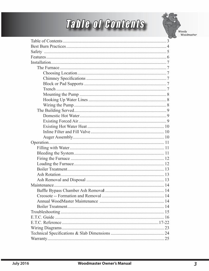
T a b l e o f C o n t e n t sTable of Contents ............................................................................................. 3Best Burn Practices .......................................................................................... 4Safety .............................................................................................................. 5Features ............................................................................................................ 6Installation ........................................................................................................ 7 The Furnace ................................................................................................ 7 Choosing Location ................................................................................ 7 ChimneySpecifications ........................................................................ 7 Block or Pad Supports .......................................................................... 7 Trench ................................................................................................... 7 Mounting the Pump .............................................................................. 8 Hooking Up Water Lines ...................................................................... 8 Wiring the Pump ................................................................................... 8 The Building Served ................................................................................... 9 Domestic Hot Water .............................................................................. 9 Existing Forced Air ............................................................................... 9 Existing Hot Water Heat ..................................................................... 10 Inline Filter and Fill Valve .................................................................. 10 Auger Assembly .................................................................................. 10Operation ........................................................................................................ 11 Filling with Water ..................................................................................... 11 Bleeding the System ................................................................................. 11 Firing the Furnace .................................................................................... 12 Loading the Furnace ................................................................................. 12 Boiler Treatment ....................................................................................... 13 Ash Rotation ............................................................................................. 13 Ash Removal and Disposal ...................................................................... 13Maintenance ................................................................................................... 14 BaffleBypassChamberAshRemoval ..................................................... 14 Creosote -- Formation and Removal ........................................................ 14 Annual WoodMaster Maintenance .......................................................... 14 Boiler Treatment ....................................................................................... 14Troubleshooting ............................................................................................. 15E.T.C. Guide .................................................................................................. 16E.T.C. Reference .......................................................................................17-22Wiring Diagrams ............................................................................................ 23TechnicalSpecifications&SlabDimensions ................................................ 24Warranty ......................................................................................................... 25
4 Woodmaster Owner’s Manual July 2016
Woody Woodmaster
B e s t B u r n P r a c t i c e s
1. Read and follow all operating instructions supplied by the manufacturer. For Commercial use only. Do not connect to a residence.
2. FUEL USED: Burn only split and seasoned wood with 25% moisture content or less. DO NOT burn green wood. Never use the following: trash, plastics, gasoline, rubber, naphtha, household garbage, material treated with petroleum products (particle board, railroad ties and pressure treated wood), leaves and cardboard.Paperproductsshouldonlybeusedwhenfiringyourfurnace.
3. LOADING FUEL:Foramoreefficientburn,paycarefulattentiontoloadingtimesandamounts.Follow the manufacturer’s written instructions for recommended loading times and amounts.
4. STARTERS:Donotuselighterfluids,gasoline,orchemicals.Usepaperproductsandkindlingonly.
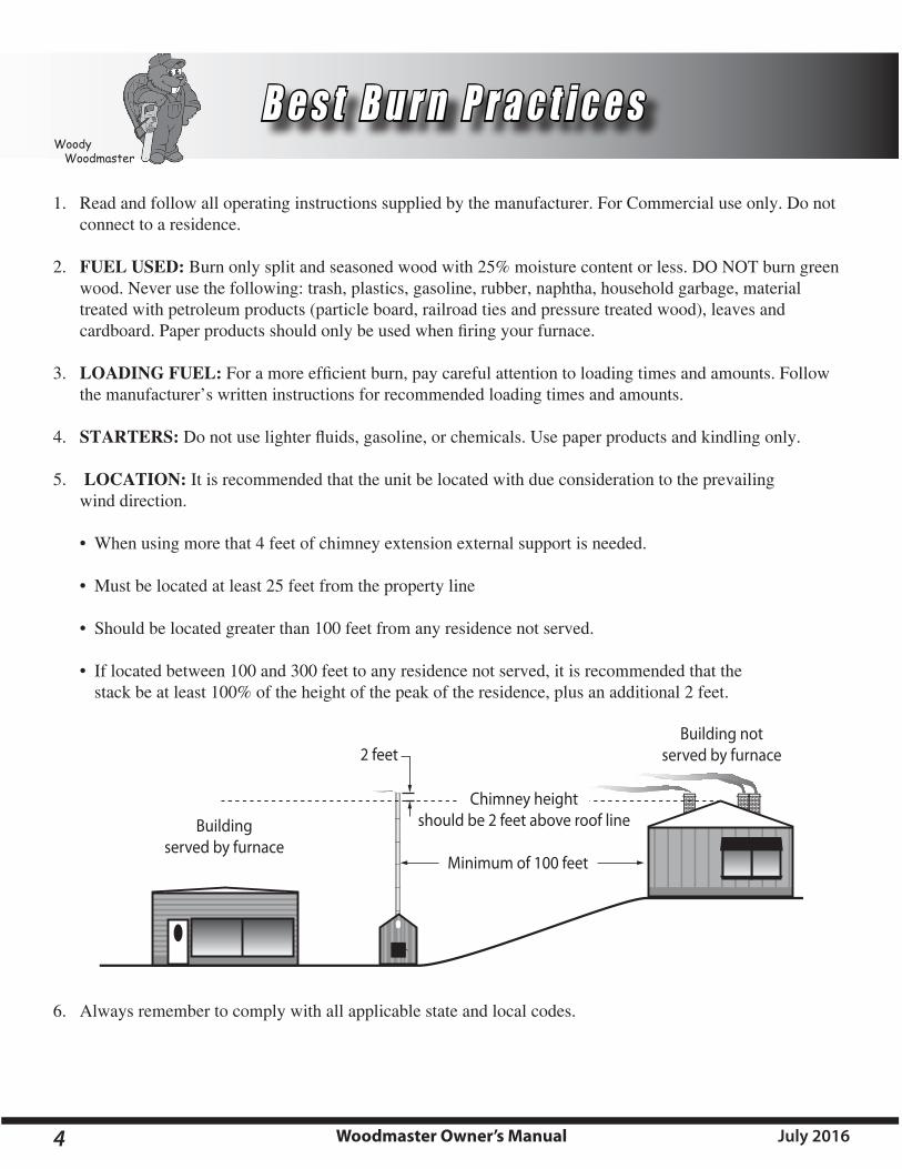
5. LOCATION: It is recommended that the unit be located with due consideration to the prevailing wind direction.
• Whenusingmorethat4feetofchimneyextensionexternalsupportisneeded.
•Mustbelocatedatleast25feetfromthepropertyline
•Shouldbelocatedgreaterthan100feetfromanyresidencenotserved.
•Iflocatedbetween100and300feettoanyresidencenotserved,itisrecommendedthatthe stackbeatleast100%oftheheightofthepeakoftheresidence,plusanadditional2feet.
6. Always remember to comply with all applicable state and local codes.
Building notserved by furnace2 feet
Buildingserved by furnace
Minimum of 100 feet
Chimney heightshould be 2 feet above roof line

5Woodmaster Owner’s ManualJuly 2016
Woody Woodmaster
IMPORTANTS INSTRUCTIONS DE SECÛRITÉ
LISEZ TOUT CES INSTRUCTIONSAVANT L’INSTALLATION
Precautions a prendre avant l’installation
Tout installations et opérations doivent être faites en accord aux régulations en force dans
votre localité, province ou etat pour le cablage electrique, la plomberie et l’opération de cette unité. Ces régulations peuvent differer de celle de ce manuel. L’installation doit être entrepris par un TechnicienQualifié.
Lisez et suivez attentivement ces directions. Conservez ce manuel aussi longtemps que
vous possederez votre WoodMaster.
Tous les models WoodMaster s’opèrent à la pression atmosphérique. NE PAS boucher ou
crée d’obstructions qui pourrai restreindre de débit du tuyau de surcharge situé directement a l’arrière de la cheminée en haut de foyer.
Le WoodMaster a été concue pour être utilisé a l’extérieure. Nous ne recommandons pas
qu’il soit installé a l’intérieure d’un batiment.
Il est recommandé par le fabricant qu’une distance minimal de 25 piéds entre le foyer et
toutbatimentsouzoneinflammable.Siplacéàproximitéd’unezoneinflammable,unebarièrreanti-étincellesdoitêtreutilisé.
L’opération de la chaudière doit être restreinte aux adultes responsable. Si la chaudière
n’est pas operé proprement, elle risque d’être endommagé et la garantie serait annulé.
Ne jamais permettre aux enfants de jouer a proximité ou de toucher la chaudière. Gardez
toujours les alentours et l’avant de la porte propre et sans materiaux combustibles.
Ne pas connecter cette unité à une chemine utilisé par un autre equipment.
Faites atteution à vos mains et doigts en mettantleboisaufourafind’éviterdeles
coincer eutre le bois et les bords de la porte.
All installation and operations must follow STATE and LOCAL CODES for wiring, plumbing,andfiringofthisunit.TheseCODES may differ from this manual. Installa-tion must be performed by a QualifiedInstaller.
Read and follow these directions carefully. Retain this manual for as long as you own your WoodMaster.
All WoodMaster models operate at atmospheric pressure. DO NOT obstruct, block, or plug inanywaytheoverflowventpipewhichislocated directly behind the chimney on top of the furnace.
The WoodMaster is designed for outdoor use. We do not recommend installing in a building.
Manufacturer recommends a minimum 25 footclearancefrombuildingsorfirehazards.Ifplacednearafirehazardareaanapprovedspark arrester should be used.
Only responsible adults should operate your furnace.Iffurnaceisnotfiredproperlydam-age could result and the warranty be voided.
Never allow small children to play near or tamper with furnace. Always keep the area around, and in front of fuel door clean and free from combustible materials.
Donotconnectthisunittoachimneyflueserv-ing another appliance.
Load Wood Carefully to avoid injury to hands andfingersthatmaycomeintocontactwithfurnace opening.
Pump must run continuously whenever the WoodMaster is being used.
Cut split seasoned wood is the recommended fuel. (approximately 25% moisture or less)
S a f e t yIMPORTANT SAFETY
INSTRUCTIONSREAD ALL INSTRUCTIONS
BEFORE INSTALLATION
Pre-Installation Precautions
6 Woodmaster Owner’s Manual July 2016
Woody Woodmaster
F e a t u r e s
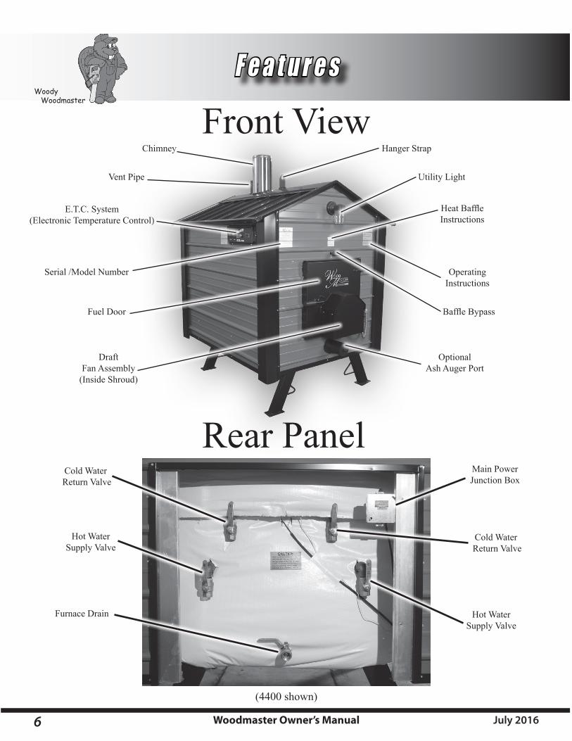
Front View
Rear Panel
Chimney
Vent Pipe
Fuel Door
E.T.C. System(Electronic Temperature Control)
Optional Ash Auger Port
Draft Fan Assembly
(Inside Shroud)
BaffleBypass
Operating Instructions
HeatBaffleInstructions
Utility Light
Hanger Strap
Serial /Model Number
Main PowerJunction Box
Furnace Drain
Hot WaterSupply Valve
Cold Water Return Valve
Cold Water Return Valve
Hot WaterSupply Valve
(4400 shown)
7Woodmaster Owner’s ManualJuly 2016
Woody Woodmaster
CAUTION!!!Using a non-insulated chimney or failure to use a Class A Insulated
Chimney WILL result in a voided warranty
I n s t a l l a t i o nTHE FURNACE
Choosing LocationThe WoodMaster is designed for outdoor use. We do not recommend installing in a building. When installing your WoodMaster, keep in mind the direction of the winds during heating months. Try to place the furnace in an area where exhaust will not be a problem for yourself or any surrounding neighbors. For commercial use only, not to be connected to a residence.
Chimney SpecificationsTo insure proper insulation, use only a Class A Insulated Chimney and Chimney Adapter from your local WoodMaster Dealer or Northwest Mfg., Inc.
Block or Pad SupportsUnder normal conditions four cement blocks are all that is required to support the furnace. Blocks should be at least 6 inches wide, 10 inches long, and 3 inches thick. Under very soft conditions a concrete pad may be needed. For Model 4400 the pad should be no less than 5 feet wide, 6 feet long, and 4 to 6 inches thick. For Model 5500 no less than 6 feet wide, 7 feet long, and 4 to 6 inches thick. Always use a non-combustible base. For model specific Slab Dimensions, see page 21 in this manual.
TrenchThe trench must be 24 inches deep and 6 to 12 inches wide. It can be dug with a shovel or a backhoe. Place all the dirt to one side of the trench to allow room for working on the other side.
WiringPlace electrical supply in bottom of trench and cover with 6 inches of dirt. Electrical wire rated for underground use (14-2 +ground or 12-2 + ground for the 6500) can be buried in the same trench as the water lines but must maintain a minimum 24 inch depth. Al-ways follow state and local codes.
Water LinesThe remaining 18 inches of open trench is where the water lines are placed. Use a one inch water line with a minimum rating of 100 PSI at 180 degrees and insure that your water line insulation has a minimum R-value of eight in order to maintain adequate heating efficiency.
NOTE: If lines travel under a driveway or where heavy equipment travels, the line should be buried two to three feet deep. If lines travel through a low or wet area, they should be insulated and installed in a water tight piping, (PVC).
NOTE: Leave a minimum of three feet of water line exposed above ground at the furnace to insure adequate length for connection.
NOTE: Before insulating and burying the water lines, label the hot water supply line at both ends. Once the lines are covered you will be able to easily determine which line is connected to the pump.
NOTE: Use only approved water line insulation sold through your WoodMaster Dealer. Poor insulation will cause your WoodMaster furnace to burn large amounts of wood.
CAUTION!!!Call Before you dig.
8 Woodmaster Owner’s Manual July 2016
Woody Woodmaster
Caution!!Never run the pumps dry!! The furnace must be full of water and the valves must be open.
I n s t a l l a t i o nTHE FURNACE
1” Cast Iron Pump Flange
Pump
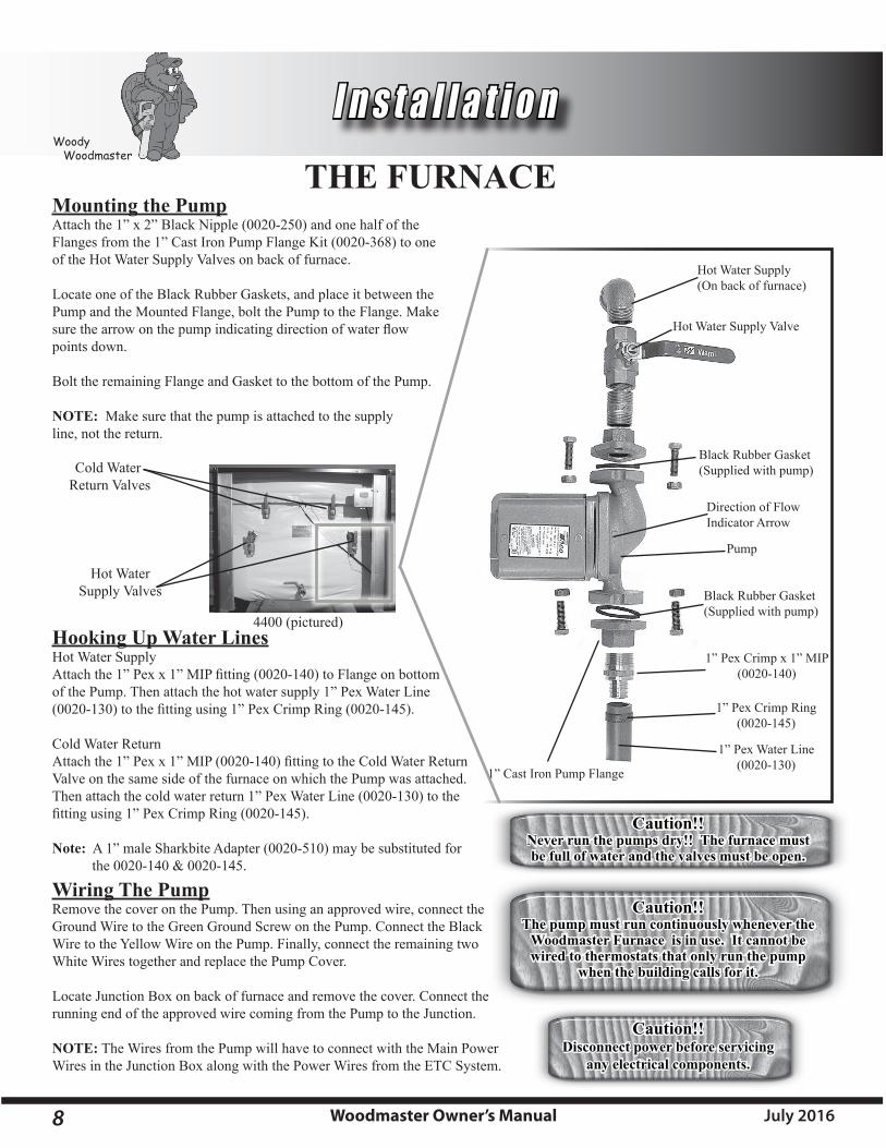
Hooking Up Water LinesHot Water SupplyAttachthe1”Pexx1”MIPfitting(0020-140)toFlangeonbottomof the Pump. Then attach the hot water supply 1” Pex Water Line (0020-130)tothefittingusing1”PexCrimpRing(0020-145).
Cold Water ReturnAttachthe1”Pexx1”MIP(0020-140)fittingtotheColdWaterReturnValve on the same side of the furnace on which the Pump was attached. Then attach the cold water return 1” Pex Water Line (0020-130) to the fittingusing1”PexCrimpRing(0020-145).
Note: A 1” male Sharkbite Adapter (0020-510) may be substituted for the0020-140&0020-145.
Wiring The PumpRemove the cover on the Pump. Then using an approved wire, connect the Ground Wire to the Green Ground Screw on the Pump. Connect the Black Wire to the Yellow Wire on the Pump. Finally, connect the remaining two White Wires together and replace the Pump Cover.
Locate Junction Box on back of furnace and remove the cover. Connect the running end of the approved wire coming from the Pump to the Junction.
NOTE: The Wires from the Pump will have to connect with the Main Power Wires in the Junction Box along with the Power Wires from the ETC System.
Black Rubber Gasket(Supplied with pump)
Hot Water Supply Valve
Black Rubber Gasket(Supplied with pump)
Hot Water Supply(On back of furnace)
Direction of Flow Indicator Arrow
Mounting the PumpAttach the 1” x 2” Black Nipple (0020-250) and one half of the Flanges from the 1” Cast Iron Pump Flange Kit (0020-368) to one of the Hot Water Supply Valves on back of furnace.
Locate one of the Black Rubber Gaskets, and place it between the Pump and the Mounted Flange, bolt the Pump to the Flange. Make surethearrowonthepumpindicatingdirectionofwaterflowpoints down.
Bolt the remaining Flange and Gasket to the bottom of the Pump.
NOTE: Make sure that the pump is attached to the supply line, not the return.
1” Pex Crimp x 1” MIP (0020-140)
1” Pex Water Line (0020-130)
1” Pex Crimp Ring (0020-145)
Caution!!The pump must run continuously whenever the
Woodmaster Furnace is in use. It cannot be wired to thermostats that only run the pump
when the building calls for it.
Caution!!Disconnect power before servicing
any electrical components.
Hot WaterSupply Valves
Cold Water Return Valves
4400 (pictured)

9Woodmaster Owner’s ManualJuly 2016
Woody Woodmaster
I n s t a l l a t i o nTHE BUILDING SERVED
Domestic Hot WaterThe Domestic Hot Water/Flatplate Kit consists of a Water toWaterHeatTransferunitandthefittingsneededtohookit up. The unit mounts on the wall VERTICALLY in your utility room and is connected as shown below.
Entering the building with water lines can be done underground or over the sill plate. Once inside the building the typical hookup wouldrunfirsttotheDomesticHotWaterSupplyandnexttoanexistingheatingsystemsuchasaforcedairfurnaceorahotwa-terheatingsystem.Finally,beforeleavingthebuilding,afillvalvemustbeinstallednearenoughtoawatersupplyforfillingandflushingtheboilerintheWoodMasterfurnace.
Existing Forced AirA water to air heat exchanger is inserted in the existing plenum. In most cases the heat exchanger is placed in a horizontal position, keeping all four sides level. Theairmustbeforcedthroughthefinnedareaoftheheatexchangerevenly.Thehotwaterlinecomingfromthehot-watertubeentersthebottomfittingoftheheatexchangerandexitsthetopfitting,whichreturnstothefurnace.Iftheplenumistoolargeortoosmall,itmustbealteredtofittheheatexchangerproperly.
NOTE: The WoodMaster Plus Water to Air Heat Exchanger must be installed below any existing Off-Peak electric coils already in the plenum.
After the installation of the WoodMaster add-on water to air exchanger, the air flowmayneedtobeincreasedtofuelfurnaces,electricfurnaces,andelectric/gasfurnaces. Methods of doing this are:
Belt Drive SystemBlowerpulleysandmotorpulleysmaybechangedbuttheelectriccurrentflow-ing through the motor shall not exceed the nameplate rating. (A blower motor or larger power may be used.)
Direct Drive SystemThe motor shall not be changed, however the speed of the motor may be in-creased.
The heat exchanger works on the same princi-pal as your car heater. Air blows through the heat exchanger, taking the heat from the water and blowing it into your existing duct work.
Hot Water Supply from WoodMaster Plus(Always put supply in lower port.)
Cold Water Return to WoodMaster Plus
Caution!!All wiring must follow state and local codes and should be done by a qualified electrician. Wire thermostats according to directions
provided by the manufacturer.
WoodMasterwater in
WoodMasterwater out
Domestic Cold Water in
Domestic Hot Water out
10 Woodmaster Owner’s Manual July 2016
Woody Woodmaster
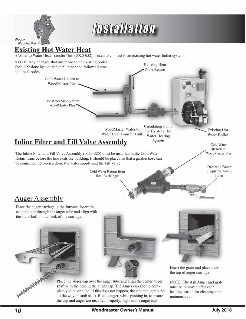
I n s t a l l a t i o nExisting Hot Water HeatA Water to Water Heat Transfer Unit (0020-052) is used to connect to an existing hot water boiler system. NOTE: Any changes that are made to an existing boiler shouldbedonebyaqualifiedplumberandfollowallstateand local codes.
The Inline Filter and Fill Valve Assembly (0020-325) must be installed in the Cold Water Return Line before the line exits the building. It should be placed so that a garden hose can be connected between a domestic water supply and the Fill Valve.
Inline Filter and Fill Valve Assembly
Hot Water Supply from WoodMaster Plus
Cold Water Return to WoodMaster Plus
Existing Heat Zone Return
WoodMaster Water to Water Heat Transfer Unit
Circulating Pump for Existing Hot Water Heating
System
Existing Hot Water Boiler
Cold Water Return from Heat Exchanger
Domestic Water Supplyforfilling
boiler
Cold Water Return to
WoodMaster Plus
Auger AssemblyPlace the auger carriage in the furnace, insert the center auger through the auger tube and align with the stub shaft on the back of the carriage.
Place the auger cap over the auger tube and align the center auger shaft with the hole in the auger cap. The Auger cap should com-pletely slide on tube. If this does not happen, the center auger is not all the way on stub shaft. Rotate auger, while pushing in, to insure the cap and auger are installed properly. Tighten the auger cap.
Insert the grate and place over the top of auger carriage.
NOTE: The Ash Auger and grate must be removed after each heating season for cleaning and maintenance .
11Woodmaster Owner’s ManualJuly 2016
Woody Woodmaster
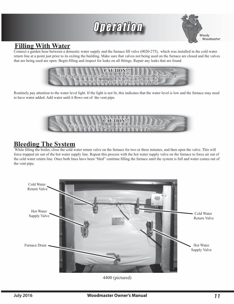
O p e r a t i o nFilling With WaterConnectagardenhosebetweenadomesticwatersupplyandthefurnacefillvalve(0020-275),whichwasinstalledinthecoldwaterreturn line at a point just prior to its exiting the building. Make sure that valves not being used on the furnace are closed and the valves thatarebeingusedareopen.Beginfillingandinspectforleaksonallfittings.Repairanyleaksthatarefound.
Routinely pay attention to the water level light. If the light is not lit, this indicates that the water level is low and the furnace may need tohavewateradded.Addwateruntilitflowsoutoftheventpipe.
Bleeding The SystemWhilefillingtheboiler,closethecoldwaterreturnvalveonthefurnacefortwoorthreeminutes,andthenopenthevalve.Thiswillforce trapped air out of the hot water supply line. Repeat this process with the hot water supply valve on the furnace to force air out of thecoldwaterreturnline.Oncebothlineshavebeen“bled”continuefillingthefurnaceuntilthesystemisfullandwatercomesoutofthe vent pipe.
CAUTION!!!Feed and return valves that are not being used must be insulated
or removed to prevent freezing and breaking.
CAUTION!!!Air in the water lines can cause damage to the pump.
Furnace Drain
Hot WaterSupply Valve
Cold Water Return Valve
Cold Water Return Valve
Hot WaterSupply Valve
4400 (pictured)

12 Woodmaster Owner’s Manual July 2016
Woody Woodmaster
O p e r a t i o n
Firing The FurnacePaperandkindlingshouldbeusedforstartingthefire.Buildasmallfire,thenaddwoodasneeded.Besurethatthepumpsarecirculatingwhenfiringthefurnace.Oncethefurnacehasreached170degrees,thefurnaceisreadytobefilledtocapacitytooperatefora12hourperiod.Loadwoodtowardsthebackofthefurnaceforimprovedefficiency.WoodMaster recommendsburningcut,splitandseasonedwood.Donotoverfillsothathotcoalsfalloutofthefurnacewhenopeningthefueldoor.Duringperiodsofwarmerweather,youmayfindittohavecreosoteinsidethefirebox.Itisimportanttofillthefurnaceonlywithenoughwoodtolasta12to24hour period. After burning your furnace for a period of time, you will discover how much wood is needed per day and what types of wood burn the best.
CAUTION!!!Donotfirewithgarbage,rubber,gasolineoranyoilproducts.Donotusechemicalsoranyoilproductsthatwerelistedabovetostartfires.
Note: The amount of wood needed to heat your system will vary depending on many different factors. System design, insulation values and type of wood are a few of the contributing factors that will determine how much wood is needed.
Loading the FurnaceBeforeopeningthefueldoorpulltheBypassBafflerodouttothefirststoppointtoventthefurnace.Use cautionwhenopeningthefueldoorsincefireandhightemperaturesmaybepresent. When loading your furnace the manufacturer recommends that you stack your wood lengthwise in two rows as shown below. This will allow air from the draft fan to circulate properly creating the optimum burn environment.
Loadthebackofthefurnacefirst,stackingthewoodlengthwiseinthefirebox.Aftertherearisloaded,fillthefrontofthefurnaceinthesamefashion.Bemindfulofthelatchonthe door when you are stacking the wood in the front.
SIDE VIEW FRONT VIEW

13Woodmaster Owner’s ManualJuly 2016
Woody Woodmaster
Ash RotationMaintaining proper ash rotation is crucial to the performance of your WoodMaster furnace. Keeping a fresh bed of coals on the top of your ashes will ensure that you get the most out of whatever kind of wood that you burn by burning and breaking down the wood to its smallest usable form. To make sure that you are rotating your ashes properly, follow the instructions below.
1. With your Ash Hoe, pull the hot coals from the back of the furnace to the front.2.Loadthebackofthefurnacefirst,stackingthewoodasshownintheprevioussection.Thenfillthefrontofthefurnace.
Byloadingthefurnaceasexplained,theflamewillbe towards the front of the furnace and work its way back. This will cause your wood to burn more thoroughly.
Boiler TreatmentAllow the system to burn for 2 hours and then add the boiler treatment as follows: Make sure that the water temperature is at least 100 degrees or higher. Add the boiler treatment that came with your furnace to the vent pipe located directly behind the chimney. Treat-ment must be added on an annual basis. If you are interested in testing the water in your furnace, contact your local dealer for details. For details on how to add your treatment while performing your annual maintenance, refer to page 14.
Ash Removal and Disposal (Weekly or as needed)Remove the ashes when the furnace is very low on wood. If your WoodMaster furnace is not equipped with an Ash Auger System use ashoveltotaketheashesfromthefrontofthefireboxandusearaketopulltheashesfromtherearofthefurnacetocreatealevelbedofhotcoals.Theashesshouldbeplacedinametalcontainerwithatightfittinglid.Theclosedcontainerofashesshouldbeplacedonanoncombustiblefloororonthegroundandwellawayfromallcombustiblematerials,pendingfinaldisposal.Ashesshouldberetained in the closed container until all of the cinders have thoroughly cooled.
CAUTION!!!Hotcoalscanlastfordays,disposingofthemimproperlyortoosooncancauseafire.
Ash Hoe
Hot CoalsAsh Bed
O p e r a t i o n

14 Woodmaster Owner’s Manual July 2016
Woody Woodmaster
M a i n t e n a n c e
Creosote -- Formation and need for removalWhen wood is burned slowly, it produces tar and other organic vapors, which combine with expelled moisture to form creosote. The creosotevaporscondenseintherelativelycoolchimneyflueofaslow-burningfire.Asaresult,creosoteresidueaccumulatesonthefluelining.Whenignitedthiscreosotemakesanextremelyhotfire.Thechimneyconnectorandchimneyshouldbeinspectedatleasttwice monthly during the heating season to determine if a creosote buildup has occurred. If creosote has accumulated it should be removedtoreducetheriskofachimneyfire.
BOILER TREATMENT: Itisveryimportanttodrainandflushyourfurnaceeachspring.Todrainfurnace--opendrainvalveandletfurnaceemptycompletely.Toflush--leavedrainvalveopenandclosepumpvalve.Addwatertofurnacethroughthereturnlines.Letflushforseveralminutes.Closedrainvalveandopenpumpvalve.Refillfurnaceandtreatwater right away.
Leaving your furnace empty exposes the water jacket to oxygen which will shorten the life of your furnace. If your system has anti-freeze, you do not need to drain it. However you should then test your water annually. For water sampling contact your dealer.
Annual WoodMaster MaintenancePROTECTyourfirechamberbyplacingthechimneycapoverthechimneyduringtheoff-season,inspectallsiliconecaulkingandmake sure it has a good seal so moisture can’t enter furnace. If you have an ash auger, remove it, clean out all ashes and scrape excess creosotefromthefirechambersurface.Reinstalltheashauger.Moisturecombinedwithasheswilleatthroughmetalinaveryshorttime.
CAUTION!!!Warranty does not cover ash corrosion! Neglecting to clean your furnace or cover the chimney,
when not in use, will void your warranty. When the furnace is in use , be sure that you maintain a good ash rotation. This should be done weekly.
If you are using a spark arrester or a chimney cap, you will need to provide your furnace with a little more maintenance. It is very important that you keep these areas free of any creosote build up at all times. Failure to do this will cause harm to the roof of your furnace.
Caution!!Use of a Spark Arrester or chimney cap will require extra care and
maintenance. If you don’t maintain it properly, it may cause damage to your roof.
Caution!!Youmustfillwithboilertreatmentannually.
Baffle Bypass Ash Removal (Weekly or as needed)ToensurethatyourBaffleBypassremainsclearofanyexcessivebuild-up,youwillneedtocleanitout.ToeffectivelycleanouttheBaffleBypassyoumust:
1. Pull the rod back until it hits the stop.2. Twist the rod clockwise and pull back in order to pass over the stop.3.SliderodinandoutseveraltocleantheBaffleBypass.4. Slide the rod all the way in.
15Woodmaster Owner’s ManualJuly 2016
Woody Woodmaster
T r o u b l e s h o o t i n g
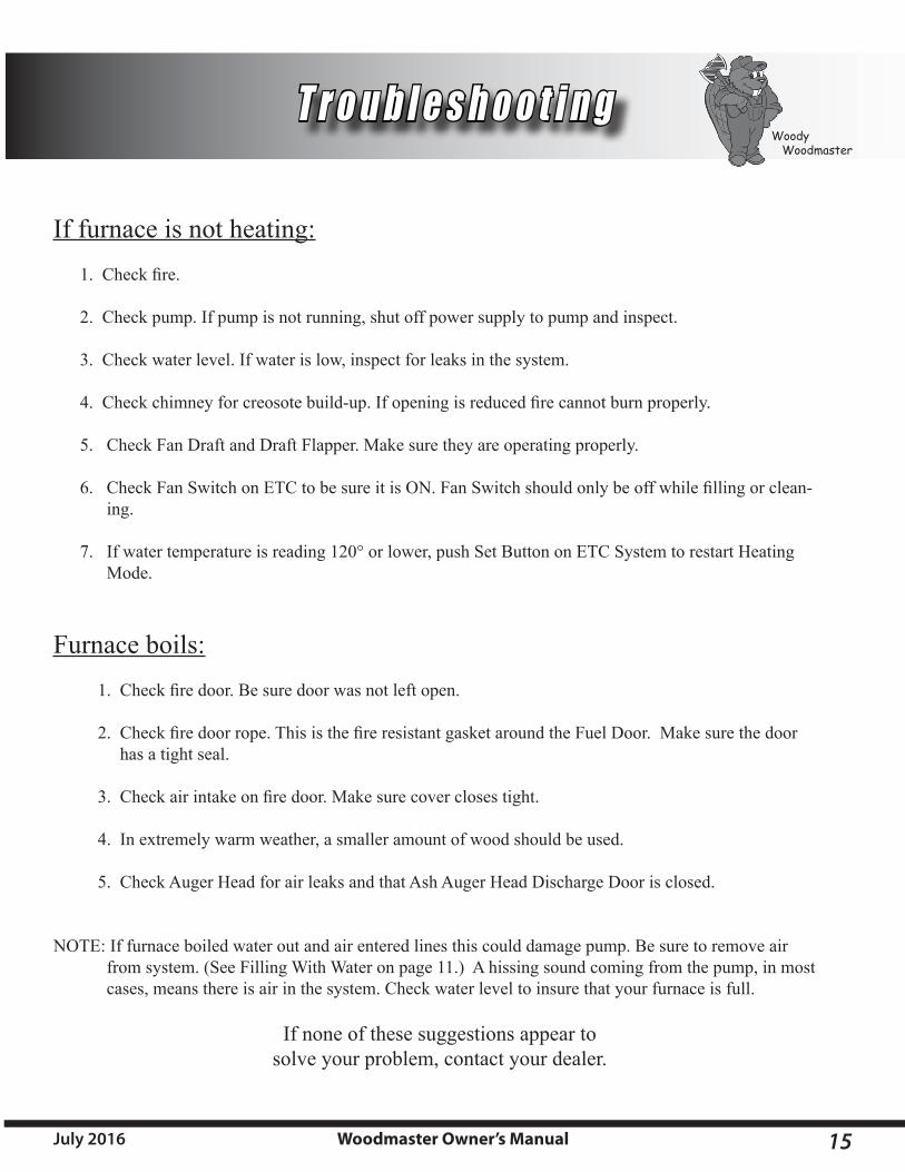
If furnace is not heating:1.Checkfire.
2. Check pump. If pump is not running, shut off power supply to pump and inspect.
3. Check water level. If water is low, inspect for leaks in the system.
4.Checkchimneyforcreosotebuild-up.Ifopeningisreducedfirecannotburnproperly.
5. Check Fan Draft and Draft Flapper. Make sure they are operating properly.
6. CheckFanSwitchonETCtobesureitisON.FanSwitchshouldonlybeoffwhilefillingorclean-ing.
7. If water temperature is reading 120° or lower, push Set Button on ETC System to restart Heating Mode.
Furnace boils: 1.Checkfiredoor.Besuredoorwasnotleftopen.
2.Checkfiredoorrope.ThisisthefireresistantgasketaroundtheFuelDoor.Makesurethedoor has a tight seal.
3.Checkairintakeonfiredoor.Makesurecoverclosestight.
4. In extremely warm weather, a smaller amount of wood should be used.
5. Check Auger Head for air leaks and that Ash Auger Head Discharge Door is closed.
NOTE: If furnace boiled water out and air entered lines this could damage pump. Be sure to remove air from system. (See Filling With Water on page 11.) A hissing sound coming from the pump, in most cases, means there is air in the system. Check water level to insure that your furnace is full.
If none of these suggestions appear tosolve your problem, contact your dealer.

16 Woodmaster Owner’s Manual July 2016
Woody Woodmaster
E . T. C . G u i d e
ELECTRONIC TEMPERATURE CONTROL (ETC):
Function: (Factory Settings below)• TheETCmonitorsandcontrolstheWoodMasterwatertemperaturebycontrollingthedraftanddraftfan.• Duringnormaloperation(adequatewoodsupply)thecontrollerwillturnoffthedraftanddraftfanwhenthewaterreaches170°F
(Set) and will turn on the draft and draft fan when the water falls 10° F (Hy).• Duringshutdown(lowwoodsupply)orwhenthewaterfallsto120°F(ALL)thecontrollerwillshutoffthedraftanddraftfan.At
thistime,theWoodMasterwillneedtobefilledwithwoodandtheETCwillneedtobereset(seeStartup)
Energy Start Shut-Down:• ThisfunctionshutsdowntheWoodMasterdraftanddraftfanwhennotinuseandback-upsystemisoperating(example:ifgone
fortheweekend,woodfiringfurnacerunsoutofwoodandback-upsystemtakesover).TorestarttheWoodMaster,simplypushtheSet Button.
Start Up / Reset• ThefirsttimetheWoodMasterispowereduporwhenithasshutdown,thecontrollerdisplaywillflash“LA”(LowAlarm)two
times and then display the water temperature for two seconds and then start over. This is normal and indicates the system has shut down because the water is at or below 120° F.
• Tostartup(orreset)yourWoodMaster,pressthesetbuttononetime.Thedisplaywillindicate“rSt”(reset)andafter1to2seconds,thedraftwillopenandthedraftfanwillturnon.Thedisplaywillcontinuetoflash“LA”andthewatertemperaturewill be displayed until the water temperature reaches 140° (ALL + 20). After water temperature reaches 140° F, only the water temperature will be displayed until the water temperature falls to 120° F.
• Note: The fan switch must be in the on position.• Note: Fan switch can be shut off when loading or for servicing.
Parameter Description and Factory Settings:• Set(setpoint)-170°F• Hy(Differential)-10°F• ALL(LowAlarm)-120°F
How To:• View Set Point — Push and immediately release the set key, display will indicate set point and will return to water temperature
after 5 seconds.• Change the Set Point — Push and hold the set key until the set point is displayed, change the value using the up and down arrows,
andpressthesetkey.Thesetpointwillflashafewtimesandthenthedisplaywillreturntowatertemperature.• Change Hy or ALL — Push and hold the set and down arrow keys at the same time until HY is displayed. Using the up and down
arrows, select the parameter to be changed (Hy or ALL), push the set key once (value of parameter should be displayed), use arrowstochangevalue,andpushthesetkey(valueshouldflashafewtimes).After10-15secondsthedisplaywillchangebacktowater temperature.
Green Float Light:• Greenlighton:WaterlevelO.K.• Greenlightoff:Waterlevellow,addwaterthroughventpipe.
Light Switch: Operates light.
Fan Switch:Thefanswitchmustbeonduringnormaloperation,butmaybeturnedofftofillfurnaceorformaintenance.

17Woodmaster Owner’s ManualJuly 2016
Woody Woodmaster
E . T. C . R e f e r e n c e
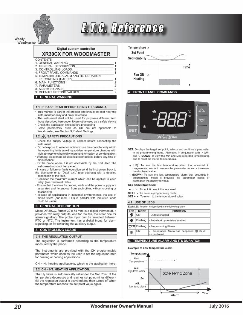
Time
Temperature
Fan ONHeating
Set PointSet Point- Hy
4. FRONT PANEL COMMANDS
LED1
LED 2
SET: Displays the target set point; selects and confirms a parameter in the programming mode. Also used in conjunction with (UP) and (DOWN) to view the Min and Max recorded temperatures and to reset the stored temperatures.
�
�
�
�
(UP): To see the last temperature alarm that occurred; in programming mode it browses the parameter codes or increases the displayed value.
�
�
�
�
(DOWN) To see the last temperature alarm that occurred; in programming mode it browses the parameter codes or decreases the displayed value.
KEY COMBINATIONS: + To lock & unlock the keyboard.
SET + To enter in programming mode. SET + To return to the temperature display.
4.1 USE OF LEDS Each LED function is described in the following table.
LED MODE FUNCTION
ON - Output enabled
Flashing - Programming Phase (flashing with LED1) - Anti-short cycle delay enabled
LED1 Flashing - Programming Phase (flashing with ) LED2 ON - Temperature Alarm has happened, LED2 stays
on until reset
5. TEMPERATURE ALARM AND ITS DURATION Example of Low temperature alarm
Digital custom controller
XR30C FOR WOODMASTER
1. GENERAL WARNING
1.1 PLEASE READ BEFORE USING THIS MANUAL
1.2 SAFETY PRECAUTIONS
2. GENERAL DESCRIPTION
3. CONTROLLING LOADS
3.1 THE REGULATION OUTPUT
3.2 CH = HT: HEATING APPLICATION.
CONTENTS1. GENERAL WARNING ___________________________ 12. GENERAL DESCRIPTION_______________________ 13. CONTROLLING LOADS_________________________ 14. FRONT PANEL COMMANDS _____________________ 15. TEMPERATURE ALARM AND ITS DURATION RECORDING (HACCP)_________________________ 16. MAIN FUNCTIONS_____________________________ 27. PARAMETERS________________________________ 28. ALARM SIGNALS______________________________ 29. DEFAULT SETTING VALUES ____________________ 2
• This manual is part of the product and should be kept near the instrument for easy and quick reference• The instrument shall not be used for purposes different from those described hereunder. It cannot be used as a safety device• Check the application limits before proceeding• Some parameters, such as CH are not applicable to Woodmaster see default settings grid fig. 15 on next page
• Check the supply voltage is correct before connecting the instrument• Do not expose to water or moisture: use the controller only within the operating limits avoiding sudden temperature changes with high atmospheric humidity to prevent formation of condensation• Warning: disconnect all electrical connections before any kind of maintenance• Fit the probe where it is not accessible by the End User. The instrument must not be opened• In case of failure or faulty operation send the instrument back tothe distributor or to “Dixell s.r.l.” (see address) with a detailed description of the fault• Consider the maximum current, which can be applied to each relay (see Technical Data)• Ensure that the wires for probes, loads and the power supply are separated and far enough from each other, without crossing or intertwining• In case of applications in industrial environments, the use of mains filters (our mod. FT1) in parallel with inductive loads could be useful
Model XR30C, format 32 x 74 mm, is a digital thermostat. Itprovides two relay outputs, one for the fan, the other one foralarm signalling. The probe input can be selected betweenPTC or NTC. The instrument has a digital input, for alarmsignalling, or for switching the auxiliary output.
The regulation is performed according to the temperaturemeasured by the probe.
The instruments are provided with the CH programmable parameter, which enables the user to set the regulation bothfor heating or cooling applications:
CH = Ht: heating applications, which is the application here.
The Hy value is automatically set under the Set Point. If thetemperature decreases and reaches set point minus differen-tial the regulation output is activated and then turned off whenthe temperature reaches the set point value again.
Alarm
18 Woodmaster Owner’s Manual July 2016
Woody Woodmaster
E . T. C . R e f e r e n c e
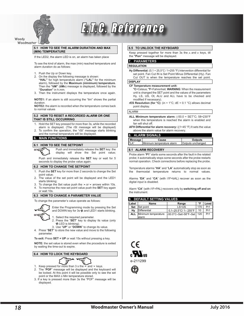
If the LED2, the alarm LED is on, an alarm has taken place
To see the kind of alarm, the max (min) reached temperature andalarm duration do as follows:
1. Push the Up or Down key.2. On the display the following message is shown: “HAL” for high temperature alarm (“LAL” for the minimum alarm), followed by the Maximum (minimum) temperature. Then the “tiM” (tiMe) message is displayed, followed by the “Duration” in h.mm.3. Then the instrument displays the temperature once again.
NOTE1: if an alarm is still occurring the “tim” shows the partialduration.NOTE2: the alarm is recorded when the temperature comes backto normal values
1. Hold the SET key pressed for more than 3s, while the recorded alarm is displayed. (The rSt message will be displayed)2. To confirm the operation, the “rSt” message starts blinking and the normal temperature will be displayed.
Push and immediately release the SET key: the display will show the Set point value;
Push and immediately release the SET key or wait for 5 seconds to display the probe value again.
1. Push the SET key for more than 2 seconds to change the Set point value;2. The value of the set point will be displayed and the LED1 starts blinking;3. To change the Set value push the or arrows within 10s.4. To memorise the new set point value push the SET key again or wait 10s.
To change the parameter’s value operate as follows:
Enter the Programming mode by pressing the Set and DOWN key for 3s and LED1 starts blinking.
1. Select the required parameter. 2. Press the “SET” key to display its value (only LED is blinking). 3. Use “UP” or “DOWN” to change its value.4. Press “SET” to store the new value and move to the following parameter.
To exit: Press SET + UP or wait 15s without pressing a key.
NOTE: the set value is stored even when the procedure is exitedby waiting the time-out to expire.
1. Keep pressed for more than 3 s the and keys.2. The “POF” message will be displayed and the keyboard will be locked. At this point it will be possible only to see the set point or the MAX o Min temperature stored.3. If a key is pressed more than 3s the “POF” message will be displayed.
5.1 HOW TO SEE THE ALARM DURATION AND MAX (MIN) TEMPERATURE
5.2 HOW TO RESET A RECORDED ALARM OR ONE THAT IS STILL OCCURRING
6. MAIN FUNCTIONS
6.1 HOW TO SEE THE SETPOINT
6.2 HOW TO CHANGE THE SETPOINT
6.3 HOW TO CHANGE A PARAMETER VALUE
6.4 HOW TO LOCK THE KEYBOARD
6.5 TO UNLOCK THE KEYBOARD
7. PARAMETERS REGULATION
DISPLAY
ALARM
8. ALARM SIGNALS Message Cause Outputs “LA” Minimum temperature alarm Outputs unchanged.
8.1 ALARM RECOVERY
9. DEFAULT SETTING VALUES Label Name Range °F Level
Set 1rP071 SU÷SL tniop teSHy Differential 0,125.5°C/ 1 255°F 10 Pr1
ALL Minimum temperature alarm
-50.0°CSet/-58°FSet 120 Pr1
Keep pressed together for more than 3s the and keys, tillthe “Pon” message will be displayed.
Hy Differential: (0,1 ÷ 25,5°C / 1÷255 °F) Intervention differential for set point. Fan Cut IN is Set Point Minus Differential (Hy). Fan Cut OUT is when the temperature reaches the set point.
CF Temperature measurement unit: °C=Celsius; °F=Fahrenheit. WARNING: When the measurement unit is changed the SET point and the values of the parameters Hy, LS, US, Ot, ALU and ALL have to be checked and modified if necessary).rES Resolution (for °C): (in = 1°C; dE = 0.1 °C) allows decimal point display.
ALL Minimum temperature alarm: (-50.0 ÷ SET°C; 58÷230°F when this temperature is reached the alarm is enabled and fan will shut off.AFH Differential for alarm recovery: ((1÷45 °F) It sets the value above the alarm value for alarm recovery.
Probe alarm “P1” starts some seconds after the fault in the relatedprobe; it automatically stops some seconds after the probe restartsnormal operation. Check connections before replacing the probe.
Temperature alarms “HA” and “LA” automatically stop as soon asthe thermostat temperature returns to normal values.
Alarms “EA” and “CA” (with i1F=bAL) recover as soon as thedigital input is disabled.
Alarm “CA” (with i1F=PAL) recovers only by switching off and onthe instrument.

19Woodmaster Owner’s ManualJuly 2016
Woody Woodmaster
E . T. C . R e f e r e n c e
(Fig. 2)
(Fig. 6)
(Fig. 5)
(Fig. 4)
(Fig. 3)
(Fig. 1)
WoodMaster Digital Aqua Stat Settings
Set Point (SP) 170° F 76.7° CDifferential (HY) 10° F 5.5° CLow Alarm (ALL) 120° F 48.9° C
Factory Settings
WoodMaster Digital Aqua Stat Minimum and Maxi-mum Settings
SetPoint(SP) 100°Fto180°F 38°Cto82°CDifferential (HY) 1° F to 45° F 1° C to 25° CLowAlarm(ALL) -67°Fto302° F -55°Cto150°C
Caution!!Do not set your (SP) lower than your (ALL)!
Changing E.T.C. SettingsFor units equipped with the XR30C
Changing the Set Point
1. Press and hold the set button for 3 seconds or until the fan symbol is flashing.ThenumberthatappearedistheSetPoint.(Fig.1)2.Usetheupordownarrowbuttonstoadjustthesetting.3.Pressthesetbuttontolockinthesetting.
Changing the Hy1. Press and hold the arrow down and set buttons until the display reads Hy. (Fig. 2)2. Release the arrow down and set buttons.3. Press set button, the number displayed is the differential. (Fig. 3)4.Pressthearrowupordownbuttontoadjust.(Fig.4)5. Press the set button. (Fig. 5)6.ThedisplaywillreadALLforapproximately30seconds,itwill then return to the water temperature reading. (Fig. 6)
Changing the ALL1.WhentheETCreadsALLfromthepreviousstep,presstheset button. The number that appears is the Low Alarm temperature.2.Toadjustthenumberpresstheupordownarrow.3.PresstheSetbuttontolockinthesetting.
DefinitionsSet Point- The temperature at which the fan will shut down.HyakaDifferential- The amount, in degrees, the temperature has to drop in order to start the fan.ALL-akaLow Alarm- The temperature at which the furnace will shut down.
Note: The procedures are the same wether you are using degrees (F) or degrees (C).
20 Woodmaster Owner’s Manual July 2016
Woody Woodmaster
Time
Temperature
Fan ONHeating
Set PointSet Point- Hy
4. FRONT PANEL COMMANDS
SET: Displays the target set point; selects and confirms a parameter in the programming mode. Also used in conjunction with (UP) and (DOWN) to view the Min and Max recorded temperatures and to reset the stored temperatures.
�
�
�
�
(UP): To see the last temperature alarm that occurred; in programming mode it browses the parameter codes or increases the displayed value.
�
�
�
�
(DOWN) To see the last temperature alarm that occurred; in programming mode it browses the parameter codes or decreases the displayed value.
KEY COMBINATIONS: + To lock & unlock the keyboard.
SET + To enter in programming mode. SET + To return to the temperature display.
4.1 USE OF LEDS Each LED function is described in the following table.
5. TEMPERATURE ALARM AND ITS DURATION Example of Low temperature alarm
Digital custom controller
XR30CX FOR WOODMASTER
1. GENERAL WARNING
1.1 PLEASE READ BEFORE USING THIS MANUAL
1.2 SAFETY PRECAUTIONS
2. GENERAL DESCRIPTION
3. CONTROLLING LOADS
3.1 THE REGULATION OUTPUT
3.2 CH = HT: HEATING APPLICATION.
CONTENTS1. GENERAL WARNING ___________________________ 12. GENERAL DESCRIPTION_______________________ 13. CONTROLLING LOADS_________________________ 14. FRONT PANEL COMMANDS _____________________ 15. TEMPERATURE ALARM AND ITS DURATION RECORDING (HACCP)_________________________ 16. MAIN FUNCTIONS_____________________________ 27. PARAMETERS________________________________ 28. ALARM SIGNALS______________________________ 29. DEFAULT SETTING VALUES ____________________ 2
• This manual is part of the product and should be kept near the instrument for easy and quick reference• The instrument shall not be used for purposes different from those described hereunder. It cannot be used as a safety device• Check the application limits before proceeding• Some parameters, such as CH are not applicable to Woodmaster, see Section 9, Default Settings.
• Check the supply voltage is correct before connecting the instrument.• Do not expose to water or moisture: use the controller only within the operating limits avoiding sudden temperature changes with high atmospheric humidity to prevent formation of condensation.• Warning: disconnect all electrical connections before any kind of maintenance.• Fit the probe where it is not accessible by the End User. The instrument must not be opened.• In case of failure or faulty operation send the instrument back tothe distributor or to “Dixell s.r.l.” (see address) with a detailed description of the fault.• Consider the maximum current which can be applied to each relay. (see Technical Data)• Ensure that the wires for probes, loads and the power supply are separated and far enough from each other, without crossing or intertwining.• In case of applications in industrial environments, the use of mains filters (our mod. FT1) in parallel with inductive loads could be useful.
Model XR30CX, format 32 x 74 mm, is a digital thermostat. Itprovides two relay outputs, one for the fan, the other one foralarm signalling. The probe input can be selected betweenPTC or NTC. The instrument has a digital input, for alarmsignalling, or for switching the auxiliary output.
The regulation is performed according to the temperaturemeasured by the probe.
The instruments are provided with the CH programmable parameter, which enables the user to set the regulation bothfor heating or cooling applications:
CH = Ht: heating applications, which is the application here.
The Hy value is automatically set under the Set Point. If thetemperature decreases and reaches set point minus differen-tial the regulation output is activated and then turned off whenthe temperature reaches the set point value again.
Alarm
LED MODE FUNCTION
ON - Output enabled
Flashing - Anti-short cycle delay enabled
Flashing - Programming Phase
ON - Temperature Alarm has happened, stays on until reset
E . T. C . R e f e r e n c e

21Woodmaster Owner’s ManualJuly 2016
Woody Woodmaster
If the alarm LED is on, an alarm has taken place
To see the kind of alarm, the max (min) reached temperature andalarm duration do as follows:
1. Push the Up or Down key.2. On the display the following message is shown: “HAL” for high temperature alarm (“LAL” for the minimum alarm), followed by the Maximum (minimum) temperature. Then the “tiM” (tiMe) message is displayed, followed by the “Duration” in h.mm.3. Then the instrument displays the temperature once again.
NOTE1: if an alarm is still occurring the “tim” shows the partialduration.NOTE2: the alarm is recorded when the temperature comes backto normal values.
1. Hold the SET key pressed for more than 3s, while the recorded alarm is displayed. (The rSt message will be displayed)2. To confirm the operation, the “rSt” message starts blinking and the normal temperature will be displayed.
Push and immediately release the SET key: the display will show the Set point value;
Push and immediately release the SET key or wait for 5 seconds to display the probe value again.
1. Push the SET key for more than 2 seconds to change the Set point value;2. The value of the set point will be displayed and the “˚C” or “˚F” starts blinking;3. To change the Set value push the or arrows within 10s.4. To memorise the new set point value push the SET key again or wait 10s.
To change the parameter’s value operate as follows:
1. Enter the Programming mode by pressing Set and keys for three seconds. (the “˚C” or”˚F” LED start blinking)
2. Select the required parameter. Press the SET” key to display its value.
3. Use “UP” or “DOWN” to change its value.
4. Press “SET” to store the new value and move to the following parameter.
To exit: Press SET + UP or wait 15s without pressing a key.
NOTE: the set value is stored even when the procedure is exitedby waiting the time-out to expire.
1. Keep pressed for more than 3 s the and keys.2. The “POF” message will be displayed and the keyboard will be locked. At this point it will be possible only to see the set point or the MAX o Min temperature stored.3. If a key is pressed more than 3s the “POF” message will be displayed.
5.1 HOW TO SEE THE ALARM DURATION AND MAX (MIN) TEMPERATURE
5.2 HOW TO RESET A RECORDED ALARM OR ONE THAT IS STILL OCCURRING
6. MAIN FUNCTIONS
6.1 HOW TO SEE THE SETPOINT
6.2 HOW TO CHANGE THE SETPOINT
6.3 HOW TO CHANGE A PARAMETER VALUE
6.4 HOW TO LOCK THE KEYBOARD
6.5 TO UNLOCK THE KEYBOARD
7. PARAMETERS REGULATION
DISPLAY
ALARM
8. ALARM SIGNALS Message Cause Outputs “LA” Minimum temperature alarm Outputs unchanged.
8.1 ALARM RECOVERY
9. DEFAULT SETTING VALUES Label Name Range °F Level
Set 1rP071 SU÷SL tniop teSHy Differential 0,125.5°C/ 1 255°F 10 Pr1
ALL Minimum temperature alarm
-50.0°CSet/-58°FSet 120 Pr1
Keep pressed together for more than 3s the and keys, tillthe “Pon” message will be displayed.
Hy Differential: (0,1 ÷ 25,5°C / 1÷255 °F) Intervention differential for set point. Fan Cut IN is Set Point Minus Differential (Hy). Fan Cut OUT is when the temperature reaches the set point.
CF Temperature measurement unit: °C=Celsius; °F=Fahrenheit. WARNING: When the measurement unit is changed the SET point and the values of the parameters Hy, LS, US, Ot, ALU and ALL have to be checked and modified if necessary).rES Resolution (for °C): (in = 1°C; dE = 0.1 °C) allows decimal point display.dLy Display Delay: (0 ÷20.0m; risul. 10s) when the temperature increases, the display is updateed of 1°C/1°F after this time.
ALL Minimum temperature alarm: (-50.0 ÷ SET°C; 58÷230°F when this temperature is reached the alarm is enabled and fan will shut off.AFH Differential for alarm recovery: ((1÷45 °F) It sets the value above the alarm value for alarm recovery.
Probe alarm “P1” starts some seconds after the fault in the relatedprobe; it automatically stops some seconds after the probe restartsnormal operation. Check connections before replacing the probe.
Temperature alarms “HA” and “LA” automatically stop as soon asthe thermostat temperature returns to normal values.
Alarms “EA” and “CA” (with i1F=bAL) recover as soon as thedigital input is disabled.
Alarm “CA” (with i1F=PAL) recovers only by switching off and onthe instrument.
E . T. C . R e f e r e n c e

22 Woodmaster Owner’s Manual July 2016
Woody Woodmaster
Changing the Set Point1. Press and hold the set button for 3 seconds or until the ˚C/˚F is flashing. The number that appears is the Set Point. (Fig. 1)2. Use the up or down arrow buttons to adjust the setting.3. Press the set button to lock in the settings.
Changing the Hy1. Press and hold the down arrow and set buttons until the display reads Hy. (Fig. 2)3. Press set button, the number displayed is the differential. (Fig. 3)2. Release the arrow down and set buttons.4. Press the arrow up or down button to adjust. (Fig. 4)5. Press the set button. (Fig. 5)6. The display will read ALL for approximately 30 seconds, (Fig. 5) it will then return to the water temperature reading. (Fig. 6)
Changing the All1. When the E.T.C. reads ALL from the previous step press the set -button. The number that appears is the Low Alarm temperature.2. To adjust the number press the up or down arrow.3. Press the Set button to lock in the setting.
DefinitionsSet Point- The temperature at which the fan will shut down, until hysteresis is achieved.Hy aka Differential- The amount, in degrees, the temperature has to drop in order to start the fan.ALL aka Low Alarm- The temperature at which the furnace will shut down. At which point the furnace should be reloaded and the control is reset.Note: The temperature scale can be changed from Fahrenheit to Celsius with the hot key from your WoodMaster Dealer.
WoodMaster Digital Aqua Stat Factory Settings
Do not set your (SP) lower than your (ALL)!CAUTION!!
(Fig. 1)
(Fig. 2)
(Fig. 3)
(Fig. 4)
(Fig. 5)
(Fig. 6)
Set Point (SP) 170° F 76.7°CDifferential (HY) 10° F 5.5°CLow Alarm (ALL) 120° F 48.9°C
WoodMaster Digital Aqua StatMinimum and Maximum Factory Settings
Set Point (SP) 100° F to 180° F 38° C to 82° CDifferential (HY) 1° F to 45° F 1° C to 25° CLow Alarm (ALL) -67° F to 302° F -55° C to 150° C
Note: The procedures are the same wether you are using degrees (F) or degrees (C).
Changing E.T.C. SettingsFor units equipped with the XR30CX
E . T. C . R e f e r e n c e
23Woodmaster Owner’s ManualJuly 2016
Woody Woodmaster
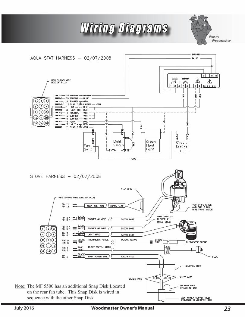
W i r i n g D i a g r a m s
The MF 5500 has an additional Snap Disk Located on the rear fan tube. This Snap Disk is wired in sequence with the other Snap Disk
Note:
k
k

24 Woodmaster Owner’s Manual July 2016
Woody Woodmaster
3300 Slab Dimensions
5500 Slab Dimensions 6500 Slab Dimensions
4400 Slab Dimensions
T e c h n i c a l S p e c i f i c a t i o n s & S l a b D i m e n s i o n s
3300 4400 5500 6500Specification
Water Capacity 105 Gallons 487 Gallons194 Gallons117 Gallons
Heating Capacity 20,000 sq. ft. 12000 sq. ft. 1
Amp. Draw@ 120v AC, 60 Hz
Max- 19.8 AmpIdle- .5 AmpAvg. Running- 6.41
5000 sq. ft. 1 10,000 sq. ft. 1
Firebox Dimensions 34” x 32” 60” x 58”50” x 56”38” x 44”
Loading Door OpeningOutside Dimensions 20” x 21” 44” x 31”27” x 27”
WeightofFurnacefilledwith water 2292 lb. 7789 lb.4450 lb.2784 lb.
24” x 24”
* Amp draw may vary depending on the revision of your furnace and external devices attached to your furnace. Maximum Amp Draw can only occur when all devices are operating, this only happens momentarily at the start up.1 Actual results will vary depending on the system, applications and insulation values.
Max- 7.5 AmpIdle- .5 AmpAvg. Running- 3.5
Max- 6.9 AmpIdle- .5 AmpAvg. Running- 2.5
Max- 6 AmpIdle- .5 AmpAvg. Running- 1.5
* ***
F= Stove Footprint

WoodMaster Limited Lifetime Warranty3300/4400/5500/6500
NORTHWEST MANUFACTURING, INC.600 Polk Ave. SW – Red Lake Falls, MN 56750
Toll free (800) 932-3629 or (218) 253-4328
Limited Lifetime Warranty on Fire Drum and Water Jacket Northwest Manufacturing, Inc. of Red Lake Falls, MN 56750 warrants material and labor on any defects in workmanship on the Fire drum and Water Jacket for a period of ten years from the purchase date to the original owner only. If there is a leak in your properly delivered and installed WoodMaster furnace in the first year, WoodMaster will replace the furnace at no cost to the original owner. (A leak means; a leak in the firebox or water jacket.) Northwest Manufacturing, Inc. will not be responsible for environmental conditions we cannot control. Therefore, Northwest Manu-facturing, Inc. will only pay these percentages of costs of warranty work per year, years two (2) through five (5) – 100% of warranty work, the sixth (6) year – 70% of warranty work, the seventh (7) year – 60% of warranty work, the eight (8) year – 40% of warranty work, the ninth (9) year – 20% of warranty work, the tenth (10) year – 10% of warranty work. Years eleven through twenty (11-20) WoodMaster will give you a 10% discount on the purchase of a new WoodMaster furnace. (furnace only) Years twenty-one (21) and beyond WoodMaster will give you a 5% discount on the purchase of a new WoodMaster furnace. (furnace only) WARNING: Northwest Manufacturing, Inc. will not warranty the inside of fire drum due to ash corrosion. Rotation of ashes must be taken care of as displayed on the maintenance list, located on the side of the furnace. The fire drum must be completely cleaned of all ashes and creosote a minimum of two (2) times per year, preferably half way through the heating season and immediately after the heating season. The chimney must be covered when the furnace is not in use. If antifreeze is not being used the water jacket must be drained and flushed yearly after each heating season. After the furnace has been drained, immediately refill completely and treat with new boiler treatment.
Two Year Warranty – Parts and LaborNorthwest Manufacturing, Inc. warrants to the original owner only, any electrical components in the furnace that is defective during normal usage for a period of two (2) years from the date of purchase.Northwest Manufacturing, Inc. warrants to the original owner only, any defects in materials or workmanship to the front door of the furnace for a period of two (2) years from the date of purchase.Northwest Manufacturing, Inc. warrants to the original owner only, any defects in materials or workmanship to the stainless steel chimney on the furnace itself for a period of two (2) years from the date of purchase.
These warranties apply only if the device is installed and operated as defined in the Owner’s Manual.Your dealer may charge you for a service call to do warranty work. Parts will be replaced on an even exchange basis.WoodMaster outdoor wood furnaces are not intended to be the only source of heat; therefore a backup system should be in place to prevent any damage caused by lack of heat. Damage caused by abuse, accidents, improper installation, overheating, corrosion, freezing or negligence will not be covered under warranty. Damage caused by burning flammable materials (such as petroleum products) will not be covered under warranty. This warranty is limited to defective parts – repair and/or replacement only, and excludes any incidental and consequential damages connected therewith. Northwest Manufacturing, Inc. is not responsible for replacement of water, water treatment, antifreeze, costs of transportation, or shipping charges. On-site service work will be offered to you. Please call Northwest Manufacturing, Inc. for current non-warranty rates.Antifreeze – Only nontoxic antifreeze is acceptable. Antifreeze will break down over a period of time and therefore should be tested annually. Always dispose of antifreeze by state and local codes. Loss of antifreeze under any condition will not be covered.How to file a claim – ANY CLAIM UNDER THIS WARRANTY MUST BE MADE TO YOUR DEALER.
Auger Stove Supplement – One Year Limited Warranty
This warranty is in addition to the warranty on your WoodMaster Northwest Manufacturing, Inc. warrants to the original owner only, material and labor on any defects in workmanship, on ash auger removable parts, including grate and auger for one (1) year from the date of purchase. Removable ash auger parts are considered and designed to be consum-able parts. Grates and augers may warp due to high heat or deteriorate over time and will have to be adjusted or replaced. This warranty will not cover warped grates or augers, nor cover deterioration due to ash corrosion. Ash auger stove modification such as the auger tube, which is welded to the stove, will carry the normal stove warranty. This warranty is limited to defective parts – repair and/or replacement only – and excludes any incidental or consequential damage connected therewith. Northwest Manufacturing, Inc. is not responsible for replacement of water, water treatment, anti-freeze, and cost of transportation or shipping charges. Once a year this Auger System must be removed from the furnace and the furnace completely cleaned out. Refer to the WoodMaster Owner’s Manual for Maintenance Procedures.
Customer’s Name ________________________________ Dealer’s Name _____________________________
Customer’s Signature _____________________________ Dealer’s Signature __________________________

Installed by: Dealer Customer
If customer, was installation explained to you?
Yes No
Type of Installation:
House/Garage Shop/Shed Greenhouse Kiln Other ____________________________
Purchased: With Auger Without Auger
Northwest Manufacturing Inc.600 Polk Ave. SWRed Lake Falls, MN 56750
Northwest Manufacturing Inc.600 Polk Ave. SWRed Lake Falls, MN 56750
PLACEPOSTAGE
HERE
Name _________________________________________
Address _______________________________________
_______________________________________________
Phone ________________________________________
Date of Purchase ________________________________
Model No. ______________________________________
Serial No. ______________________________________(Model and serial numbers are located on the decal on front of furnace.)
Dealer’s Name __________________________________
OWNER’S REGISTRATION CARD
WoodMaster Limited Lifetime Warranty3300/4400/5500/6500
NORTHWEST MANUFACTURING, INC.600 Polk Ave. SW – Red Lake Falls, MN 56750
Toll free (800) 932-3629 or (218) 253-4328
Limited Lifetime Warranty on Fire Drum and Water Jacket Northwest Manufacturing, Inc. of Red Lake Falls, MN 56750 warrants material and labor on any defects in workmanship on the Fire drum and Water Jacket for a period of ten years from the purchase date to the original owner only. If there is a leak in your properly delivered and installed WoodMaster furnace in the first year, WoodMaster will replace the furnace at no cost to the original owner. (A leak means; a leak in the firebox or water jacket.) Northwest Manufacturing, Inc. will not be responsible for environmental conditions we cannot control. Therefore, Northwest Manu-facturing, Inc. will only pay these percentages of costs of warranty work per year, years two (2) through five (5) – 100% of warranty work, the sixth (6) year – 70% of warranty work, the seventh (7) year – 60% of warranty work, the eight (8) year – 40% of warranty work, the ninth (9) year – 20% of warranty work, the tenth (10) year – 10% of warranty work. Years eleven through twenty (11-20) WoodMaster will give you a 10% discount on the purchase of a new WoodMaster furnace. (furnace only) Years twenty-one (21) and beyond WoodMaster will give you a 5% discount on the purchase of a new WoodMaster furnace. (furnace only) WARNING: Northwest Manufacturing, Inc. will not warranty the inside of fire drum due to ash corrosion. Rotation of ashes must be taken care of as displayed on the maintenance list, located on the side of the furnace. The fire drum must be completely cleaned of all ashes and creosote a minimum of two (2) times per year, preferably half way through the heating season and immediately after the heating season. The chimney must be covered when the furnace is not in use. If antifreeze is not being used the water jacket must be drained and flushed yearly after each heating season. After the furnace has been drained, immediately refill completely and treat with new boiler treatment.
Two Year Warranty – Parts and LaborNorthwest Manufacturing, Inc. warrants to the original owner only, any electrical components in the furnace that is defective during normal usage for a period of two (2) years from the date of purchase.Northwest Manufacturing, Inc. warrants to the original owner only, any defects in materials or workmanship to the front door of the furnace for a period of two (2) years from the date of purchase.Northwest Manufacturing, Inc. warrants to the original owner only, any defects in materials or workmanship to the stainless steel chimney on the furnace itself for a period of two (2) years from the date of purchase.
These warranties apply only if the device is installed and operated as defined in the Owner’s Manual.Your dealer may charge you for a service call to do warranty work. Parts will be replaced on an even exchange basis.WoodMaster outdoor wood furnaces are not intended to be the only source of heat; therefore a backup system should be in place to prevent any damage caused by lack of heat. Damage caused by abuse, accidents, improper installation, overheating, corrosion, freezing or negligence will not be covered under warranty. Damage caused by burning flammable materials (such as petroleum products) will not be covered under warranty. This warranty is limited to defective parts – repair and/or replacement only, and excludes any incidental and consequential damages connected therewith. Northwest Manufacturing, Inc. is not responsible for replacement of water, water treatment, antifreeze, costs of transportation, or shipping charges. On-site service work will be offered to you. Please call Northwest Manufacturing, Inc. for current non-warranty rates.Antifreeze – Only nontoxic antifreeze is acceptable. Antifreeze will break down over a period of time and therefore should be tested annually. Always dispose of antifreeze by state and local codes. Loss of antifreeze under any condition will not be covered.How to file a claim – ANY CLAIM UNDER THIS WARRANTY MUST BE MADE TO YOUR DEALER.
Auger Stove Supplement – One Year Limited Warranty
This warranty is in addition to the warranty on your WoodMaster Northwest Manufacturing, Inc. warrants to the original owner only, material and labor on any defects in workmanship, on ash auger removable parts, including grate and auger for one (1) year from the date of purchase. Removable ash auger parts are considered and designed to be consum-able parts. Grates and augers may warp due to high heat or deteriorate over time and will have to be adjusted or replaced. This warranty will not cover warped grates or augers, nor cover deterioration due to ash corrosion. Ash auger stove modification such as the auger tube, which is welded to the stove, will carry the normal stove warranty. This warranty is limited to defective parts – repair and/or replacement only – and excludes any incidental or consequential damage connected therewith. Northwest Manufacturing, Inc. is not responsible for replacement of water, water treatment, anti-freeze, and cost of transportation or shipping charges. Once a year this Auger System must be removed from the furnace and the furnace completely cleaned out. Refer to the WoodMaster Owner’s Manual for Maintenance Procedures.
Customer’s Name ________________________________ Dealer’s Name _____________________________
Customer’s Signature _____________________________ Dealer’s Signature __________________________
Installed by: Dealer Customer
If customer, was installation explained to you?
Yes No
Type of Installation:
Garage Shop/Shed Greenhouse Kiln Other ____________________________
Purchased: With Auger Without Auger
Northwest Manufacturing Inc.600 Polk Ave. SWRed Lake Falls, MN 56750
Northwest Manufacturing Inc.600 Polk Ave. SWRed Lake Falls, MN 56750
PLACEPOSTAGE
HERE
Name _________________________________________
Address _______________________________________
_______________________________________________
Phone ________________________________________
Date of Purchase ________________________________
Model No. ______________________________________
Serial No. ______________________________________(Model and serial numbers are located on the decal on front of furnace.)
Dealer’s Name __________________________________
OWNER’S REGISTRATION CARD
29Woodmaster Owner’s ManualJuly 2016
Woody Woodmaster
W a r r a n t y
WoodMaster Limited Lifetime Warranty3300/4400/5500/6500
NORTHWEST MANUFACTURING, INC.600 Polk Ave. SW – Red Lake Falls, MN 56750
Toll free (800) 932-3629 or (218) 253-4328
Limited Lifetime Warranty on Fire Drum and Water Jacket Northwest Manufacturing, Inc. of Red Lake Falls, MN 56750 warrants material and labor on any defects in workmanship on the Fire drum and Water Jacket for a period of ten years from the purchase date to the original owner only. If there is a leak in your properly delivered and installed WoodMaster furnace in the first year, WoodMaster will replace the furnace at no cost to the original owner. (A leak means; a leak in the firebox or water jacket.) Northwest Manufacturing, Inc. will not be responsible for environmental conditions we cannot control. Therefore, Northwest Manu-facturing, Inc. will only pay these percentages of costs of warranty work per year, years two (2) through five (5) – 100% of warranty work, the sixth (6) year – 70% of warranty work, the seventh (7) year – 60% of warranty work, the eight (8) year – 40% of warranty work, the ninth (9) year – 20% of warranty work, the tenth (10) year – 10% of warranty work. Years eleven through twenty (11-20) WoodMaster will give you a 10% discount on the purchase of a new WoodMaster furnace. (furnace only) Years twenty-one (21) and beyond WoodMaster will give you a 5% discount on the purchase of a new WoodMaster furnace. (furnace only) WARNING: Northwest Manufacturing, Inc. will not warranty the inside of fire drum due to ash corrosion. Rotation of ashes must be taken care of as displayed on the maintenance list, located on the side of the furnace. The fire drum must be completely cleaned of all ashes and creosote a minimum of two (2) times per year, preferably half way through the heating season and immediately after the heating season. The chimney must be covered when the furnace is not in use. If antifreeze is not being used the water jacket must be drained and flushed yearly after each heating season. After the furnace has been drained, immediately refill completely and treat with new boiler treatment.
Two Year Warranty – Parts and LaborNorthwest Manufacturing, Inc. warrants to the original owner only, any electrical components in the furnace that is defective during normal usage for a period of two (2) years from the date of purchase.Northwest Manufacturing, Inc. warrants to the original owner only, any defects in materials or workmanship to the front door of the furnace for a period of two (2) years from the date of purchase.Northwest Manufacturing, Inc. warrants to the original owner only, any defects in materials or workmanship to the stainless steel chimney on the furnace itself for a period of two (2) years from the date of purchase.
These warranties apply only if the device is installed and operated as defined in the Owner’s Manual.Your dealer may charge you for a service call to do warranty work. Parts will be replaced on an even exchange basis.WoodMaster outdoor wood furnaces are not intended to be the only source of heat; therefore a backup system should be in place to prevent any damage caused by lack of heat. Damage caused by abuse, accidents, improper installation, overheating, corrosion, freezing or negligence will not be covered under warranty. Damage caused by burning flammable materials (such as petroleum products) will not be covered under warranty. This warranty is limited to defective parts – repair and/or replacement only, and excludes any incidental and consequential damages connected therewith. Northwest Manufacturing, Inc. is not responsible for replacement of water, water treatment, antifreeze, costs of transportation, or shipping charges. On-site service work will be offered to you. Please call Northwest Manufacturing, Inc. for current non-warranty rates.Antifreeze – Only nontoxic antifreeze is acceptable. Antifreeze will break down over a period of time and therefore should be tested annually. Always dispose of antifreeze by state and local codes. Loss of antifreeze under any condition will not be covered.How to file a claim – ANY CLAIM UNDER THIS WARRANTY MUST BE MADE TO YOUR DEALER.
Auger Stove Supplement – One Year Limited Warranty
This warranty is in addition to the warranty on your WoodMaster Northwest Manufacturing, Inc. warrants to the original owner only, material and labor on any defects in workmanship, on ash auger removable parts, including grate and auger for one (1) year from the date of purchase. Removable ash auger parts are considered and designed to be consum-able parts. Grates and augers may warp due to high heat or deteriorate over time and will have to be adjusted or replaced. This warranty will not cover warped grates or augers, nor cover deterioration due to ash corrosion. Ash auger stove modification such as the auger tube, which is welded to the stove, will carry the normal stove warranty. This warranty is limited to defective parts – repair and/or replacement only – and excludes any incidental or consequential damage connected therewith. Northwest Manufacturing, Inc. is not responsible for replacement of water, water treatment, anti-freeze, and cost of transportation or shipping charges. Once a year this Auger System must be removed from the furnace and the furnace completely cleaned out. Refer to the WoodMaster Owner’s Manual for Maintenance Procedures.
Customer’s Name ________________________________ Dealer’s Name _____________________________
Customer’s Signature _____________________________ Dealer’s Signature __________________________

30 Woodmaster Owner’s Manual July 2016
Woody Woodmaster
N o t e s
31Woodmaster Owner’s ManualJuly 2016
Woody Woodmaster
N o t e s