physics3/25/2019 1 for scientists and engineers a strategic approach 4/ e physics randall d. knight...
TRANSCRIPT

3/25/2019
1
FOR SCIENTISTS AND ENGINEERS A STRATEGIC APPROACH 4/EPHYSICS
RANDALL D. KNIGHT
Chapter 34 Lecture
© 2017 Pearson Education, Inc. Slide 34-2
Chapter 34 Ray Optics
IN THIS CHAPTER, you will learn about and apply the ray model of light
© 2017 Pearson Education, Inc. Slide 34-3
Chapter 34 Preview

3/25/2019
2
© 2017 Pearson Education, Inc. Slide 34-4
Chapter 34 Preview
© 2017 Pearson Education, Inc. Slide 34-5
Chapter 34 Preview
© 2017 Pearson Education, Inc. Slide 34-6
Chapter 34 Preview

3/25/2019
3
© 2017 Pearson Education, Inc. Slide 34-7
Chapter 34 Preview
© 2017 Pearson Education, Inc. Slide 34-8
Chapter 34 Reading Questions
© 2017 Pearson Education, Inc. Slide 34-9
What is specular reflection?
A. The image of a specimen
B. A reflection that separates different colors
C. Reflection by a flat smooth object
D. Reflection in which the image is virtual and special
E. This topic is not covered in Chapter 34.
Reading Question 34.1

3/25/2019
4
© 2017 Pearson Education, Inc. Slide 34-10
What is specular reflection?
A. The image of a specimen
B. A reflection that separates different colors
C. Reflection by a flat smooth object
D. Reflection in which the image is virtual and special
E. This topic is not covered in Chapter 34.
Reading Question 34.1
© 2017 Pearson Education, Inc. Slide 34-11
What is diffuse reflection?
A. A reflection that separates different colors
B. Reflection by a surface with tiny irregularities that cause the reflected rays to leave in many random directions
C. Reflection that increases in size linearly with distance from the mirror
D. Reflection in which the image is virtual
E. This topic is not covered in Chapter 34.
Reading Question 34.2
© 2017 Pearson Education, Inc. Slide 34-12
What is diffuse reflection?
A. A reflection that separates different colors
B. Reflection by a surface with tiny irregularities that cause the reflected rays to leave in many random directions
C. Reflection that increases in size linearly with distance from the mirror
D. Reflection in which the image is virtual
E. This topic is not covered in Chapter 34.
Reading Question 34.2

3/25/2019
5
© 2017 Pearson Education, Inc. Slide 34-13
A paraxial ray
A. Moves in a parabolic path.
B. Is a ray that has been reflected from a parabolic mirror.
C. Is a ray that moves nearly parallel to the
optical axis.
D. Is a ray that moves exactly parallel to the
optical axis.
Reading Question 34.3
© 2017 Pearson Education, Inc. Slide 34-14
A paraxial ray
A. Moves in a parabolic path.
B. Is a ray that has been reflected from a parabolic mirror.
C. Is a ray that moves nearly parallel to the
optical axis.
D. Is a ray that moves exactly parallel to the
optical axis.
Reading Question 34.3
© 2017 Pearson Education, Inc. Slide 34-15
A virtual image is
A. The cause of optical illusions.
B. A point from which rays appear to diverge.
C. An image that only seems to exist.
D. The image that is left in space after you remove a viewing screen.
Reading Question 34.4

3/25/2019
6
© 2017 Pearson Education, Inc. Slide 34-16
A virtual image is
A. The cause of optical illusions.
B. A point from which rays appear to diverge.
C. An image that only seems to exist.
D. The image that is left in space after you remove a viewing screen.
Reading Question 34.4
© 2017 Pearson Education, Inc. Slide 34-17
The focal length of a converging lens is
A. The distance at which an image is formed.
B. The distance at which an object must be placed to form an image.
C. The distance at which parallel light rays are
focused.
D. The distance from the front surface to the back
surface.
Reading Question 34.5
© 2017 Pearson Education, Inc. Slide 34-18
The focal length of a converging lens is
A. The distance at which an image is formed.
B. The distance at which an object must be placed to form an image.
C. The distance at which parallel light rays are
focused.
D. The distance from the front surface to the back
surface.
Reading Question 34.5

3/25/2019
7
© 2017 Pearson Education, Inc. Slide 34-19
Chapter 34 Content, Examples, and
QuickCheck Questions
© 2017 Pearson Education, Inc. Slide 34-20
� Let us define a light ray as a line in the direction along which light energy is flowing.
� Any narrow beam of light, such as a laser beam, is actually a bundle of many parallel light rays.
� You can think of a single light ray as the limiting case of a laser beam whose diameter approaches zero.
The Ray Model of Light
© 2017 Pearson Education, Inc. Slide 34-21
The Ray Model of Light

3/25/2019
8
© 2017 Pearson Education, Inc. Slide 34-22
The Ray Model of Light
© 2017 Pearson Education, Inc. Slide 34-23
� Objects can be either self-luminous, such as the sun, flames, and
lightbulbs, or reflective.
� Most objects are reflective.
Objects
© 2017 Pearson Education, Inc. Slide 34-24
� The diverging rays from a point source are emitted in all directions.
� Each point on an object is a point source of light rays.
� A parallel bundle of rays could be a laser beam or light from a distant object.
Objects

3/25/2019
9
© 2017 Pearson Education, Inc. Slide 34-25
� Rays originate from every point on an object and travel outward in all directions, but a diagram trying to show all these rays would be messy and confusing.
� To simplify the picture, we use a ray diagram showing
only a few rays.
Ray Diagrams
© 2017 Pearson Education, Inc. Slide 34-26
� A camera obscura is a darkened room with a single, small hole, called an aperture.
� The geometry of the rays causes the image to be upside down.
� The object and image
heights are related by
Apertures
© 2017 Pearson Education, Inc. Slide 34-27
� We can apply the ray model to more complex apertures, such as the L-shaped aperture below.
Apertures
3/25/2019
10
© 2017 Pearson Education, Inc. Slide 34-28
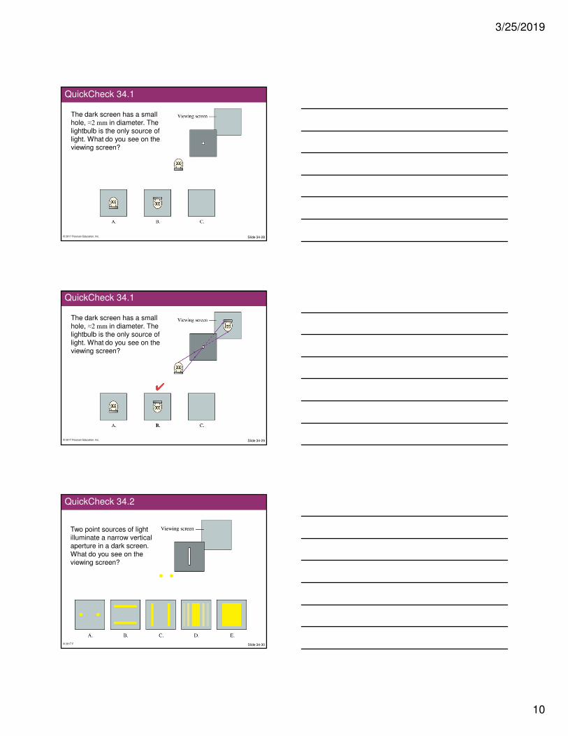
QuickCheck 34.1
The dark screen has a small hole, ≈2 mm in diameter. The lightbulb is the only source of light. What do you see on the viewing screen?
© 2017 Pearson Education, Inc. Slide 34-29
QuickCheck 34.1
The dark screen has a small hole, ≈2 mm in diameter. The lightbulb is the only source of light. What do you see on the viewing screen?
© 2017 Pearson Education, Inc. Slide 34-30
QuickCheck 34.2
Two point sources of light illuminate a narrow vertical aperture in a dark screen. What do you see on the viewing screen?

3/25/2019
11
© 2017 Pearson Education, Inc. Slide 34-31
QuickCheck 34.2
Two point sources of light illuminate a narrow vertical aperture in a dark screen. What do you see on the viewing screen?
© 2017 Pearson Education, Inc. Slide 34-32
� Reflection from a flat, smooth surface, such as a mirror or a piece of polished metal, is called specular reflection.
Specular Reflection of Light
© 2017 Pearson Education, Inc. Slide 34-33
� The law of reflection states that
1. The incident ray and the reflected ray are in the same plane normal to the surface, and
2. The angle of reflection equals the angle of incidence:
θr = θi
Reflection

3/25/2019
12
© 2017 Pearson Education, Inc. Slide 34-34
Example 34.1 Light Reflecting from a Mirror
© 2017 Pearson Education, Inc. Slide 34-35
Example 34.1 Light Reflecting from a Mirror
© 2017 Pearson Education, Inc. Slide 34-36
Example 34.1 Light Reflecting from a Mirror

3/25/2019
13
© 2017 Pearson Education, Inc. Slide 34-37
Example 34.1 Light Reflecting from a Mirror
© 2017 Pearson Education, Inc. Slide 34-38
� Most objects are seen by virtue of their reflected light.
� For a “rough” surface, the law of reflection is obeyed at each point but the irregularities of the surface cause the reflected rays to leave in many random directions.
� This situation is called diffuse reflection.
� It is how you see this slide, the wall, your
hand, your friend, and so on.
Diffuse Reflection
© 2017 Pearson Education, Inc. Slide 34-39
� Consider P, a source of rays that reflect from a mirror.
� The reflected rays appear to emanate from P′, the same distance behind the mirror as P is in front of the mirror.
� That is, s′ = s
The Plane Mirror

3/25/2019
14
© 2017 Pearson Education, Inc. Slide 34-40
The Plane Mirror
© 2017 Pearson Education, Inc. Slide 34-41
QuickCheck 34.3
You are looking at the image of a pencil in a mirror. What do you see in the mirror if the top half of the mirror is covered with a piece of dark paper?
A. The full image of the pencil
B. The top half only of the pencil
C. The bottom half only of the pencil
D. No pencil, only the paper
© 2017 Pearson Education, Inc. Slide 34-42
QuickCheck 34.3
You are looking at the image of a pencil in a mirror. What do you see in the mirror if the top half of the mirror is covered with a piece of dark paper?
A. The full image of the pencil
B. The top half only of the pencil
C. The bottom half only of the pencil
D. No pencil, only the paper

3/25/2019
15
© 2017 Pearson Education, Inc. Slide 34-43
Example 34.2 How High Is the Mirror?
© 2017 Pearson Education, Inc. Slide 34-44
Example 34.2 How High Is the Mirror?
© 2017 Pearson Education, Inc. Slide 34-45
Example 34.2 How High Is the Mirror?

3/25/2019
16
© 2017 Pearson Education, Inc. Slide 34-46
Example 34.2 How High Is the Mirror?
© 2017 Pearson Education, Inc. Slide 34-47
Example 34.2 How High Is the Mirror?
© 2017 Pearson Education, Inc. Slide 34-48
� Two things happen when a light ray is incident on a smooth boundary between two transparent materials:
1. Part of the light reflects
from the boundary, obeying the law of reflection.
2. Part of the light continues into the second medium. The transmission of light from one medium to another, but with a change in direction, is called
refraction.
Refraction

3/25/2019
17
© 2017 Pearson Education, Inc. Slide 34-49
Refraction
© 2017 Pearson Education, Inc. Slide 34-50
Refraction
© 2017 Pearson Education, Inc. Slide 34-51
Indices of Refraction

3/25/2019
18
© 2017 Pearson Education, Inc. Slide 34-52
� The figure shows a wave crossing the boundary between two media, where we’re assuming n2 > n1.
� Because the wavelengths differ on opposite sides of the boundary, the wave fronts can stay lined up only if the waves in the two media are traveling in different directions.
Refraction
© 2017 Pearson Education, Inc. Slide 34-53
A laser beam passing from medium 1 to medium 2 is refracted as
shown. Which is true?
QuickCheck 34.4
A. n1 < n2
B. n1 > n2
C. There’s not enough information to compare n1 and n2.
© 2017 Pearson Education, Inc. Slide 34-54
QuickCheck 34.4
A laser beam passing from medium 1 to medium 2 is refracted as
shown. Which is true?
A. n1 < n2
B. n1 > n2
C. There’s not enough information to compare n1 and n2.

3/25/2019
19
© 2017 Pearson Education, Inc. Slide 34-55
Tactics: Analyzing Refraction
© 2017 Pearson Education, Inc. Slide 34-56
Example 34.4 Measuring the Index of Refraction
© 2017 Pearson Education, Inc. Slide 34-57
Example 34.4 Measuring the Index of Refraction

3/25/2019
20
© 2017 Pearson Education, Inc. Slide 34-58
Example 34.4 Measuring the Index of Refraction
© 2017 Pearson Education, Inc. Slide 34-59
n1 = 1.59
Example 34.4 Measuring the Index of Refraction
© 2017 Pearson Education, Inc. Slide 34-60
� When a ray crosses a boundary into a material with a lower index of refraction, it bends away from the normal.
� As the angle θ1 increases, the refraction angle θ2 approaches 90º, and the fraction of the light energy transmitted decreases
while the fraction reflected increases.
� The critical angle of incidence occurs when θ2 = 90º:
� The refracted light vanishes at the critical angle and the reflection becomes 100% for any angle θ1 > θc.
Total Internal Reflection

3/25/2019
21
© 2017 Pearson Education, Inc. Slide 34-61
Total Internal Reflection
© 2017 Pearson Education, Inc. Slide 34-62
A laser beam undergoes two refractions plus total internal reflection at the interface between medium 2 and medium 3. Which is true?
QuickCheck 34.5
A. n1 < n3
B. n1 > n3
C. There’s not enough
information to compare n1 and n3.
© 2017 Pearson Education, Inc. Slide 34-63
QuickCheck 34.5
A laser beam undergoes two refractions plus total internal reflection at the interface between medium 2 and medium 3. Which is true?
A. n1 < n3
B. n1
> n3
C. There’s not enough
information to compare n1 and n3.

3/25/2019
22
© 2017 Pearson Education, Inc. Slide 34-64
Example 34.5 Total Internal Reflection
© 2017 Pearson Education, Inc. Slide 34-65
Example 34.5 Total Internal Reflection
© 2017 Pearson Education, Inc. Slide 34-66
Example 34.5 Total Internal Reflection

3/25/2019
23
© 2017 Pearson Education, Inc. Slide 34-67
� The most important modern application of total internal reflection (TIR) is optical fibers.
� Light rays enter the glass fiber, then impinge on the inside wall of the glass at an angle above the critical
angle, so they undergo TIR and remain inside the glass.
� The light continues to “bounce” its way down the tube as if it were inside a pipe.
Fiber Optics
© 2017 Pearson Education, Inc. Slide 34-68
� In a practical optical fiber, a small-diameter glass core is surrounded by a layer of glass cladding.
� The glasses used for the core and the cladding have
ncore > ncladding
Fiber Optics
© 2017 Pearson Education, Inc. Slide 34-69
� If you see a fish that appears to be swimming close to the front window of the
aquarium, but then look through the side of the aquarium, you’ll find that the fish is actually farther from the window than you thought.
Image Formation by Refraction

3/25/2019
24
© 2017 Pearson Education, Inc. Slide 34-70
� Rays emerge from a material with n1 > n2.
� Consider only paraxial rays, for which θ1 and θ2
are quite small.
� In this case:
where s is the object distance and s′ is the image distance.
� The minus sign tells us that
we have a virtual image.
Image Formation by Refraction
© 2017 Pearson Education, Inc. Slide 34-71
A fish in an aquarium with flat sides looks out at a hungry cat. To the fish, the distance to the cat appears to be
QuickCheck 34.6
A. Less than the actual distance.
B. Equal to the actual distance.
C. More than the actual distance.
© 2017 Pearson Education, Inc. Slide 34-72
QuickCheck 34.6
A fish in an aquarium with flat sides looks out at a hungry cat. To the fish, the distance to the cat appears to be
A. Less than the actual distance.
B. Equal to the actual distance.
C. More than the actual distance.

3/25/2019
25
© 2017 Pearson Education, Inc. Slide 34-73
Example 34.6 An Air Bubble in a Window
© 2017 Pearson Education, Inc. Slide 34-74
Example 34.6 An Air Bubble in a Window
© 2017 Pearson Education, Inc. Slide 34-75
Example 34.6 An Air Bubble in a Window

3/25/2019
26
© 2017 Pearson Education, Inc. Slide 34-76
� The photos below show parallel light rays entering two different lenses.
� The left lens, called a converging lens, causes the rays to refract toward the optical axis.
� The right lens, called a diverging lens, refracts parallel rays away from the optical axis.
Lenses
© 2017 Pearson Education, Inc. Slide 34-77
� A converging lens is thicker in the center than at the edges.
� The focal length f is the
distance from the lens at which rays parallel to the optical axis converge.
� The focal length is a
property of the lens, independent of how the lens is used.
Converging Lenses
© 2017 Pearson Education, Inc. Slide 34-78
� A diverging lens is thicker at the edges than in the center.
� The focal length f is the
distance from the lens at which rays parallel to the optical axis appear to diverge.
� The focal length is a
property of the lens, independent of how the lens is used.
Diverging Lenses

3/25/2019
27
© 2017 Pearson Education, Inc. Slide 34-79
You can use the sun’s rays and a lens to start a fire. To do so, you should use
QuickCheck 34.7
A. A converging lens.
B. A diverging lens.
C. Either a converging or a diverging lens will work if you use it correctly.
© 2017 Pearson Education, Inc. Slide 34-80
QuickCheck 34.7
You can use the sun’s rays and a lens to start a fire. To do so, you should use
A. A converging lens.
B. A diverging lens.
C. Either a converging or a diverging lens will work if you use it correctly.
© 2017 Pearson Education, Inc. Slide 34-81
� Three situations form the basis for ray tracing through a thin converging lens.
� Situation 1:
A ray initially parallel to the optic axis will go through the far focal point after
passing through the lens.
Thin Lenses: Ray Tracing

3/25/2019
28
© 2017 Pearson Education, Inc. Slide 34-82
� Three situations form the basis for ray tracing through a thin converging lens.
� Situation 2:
A ray through the near focal point of a thin lens becomes parallel to the optic axis after
passing through the lens.
Thin Lenses: Ray Tracing
© 2017 Pearson Education, Inc. Slide 34-83
� Three situations form the basis for ray tracing through a thin converging lens.
� Situation 3:
A ray through the center of a thin lens is neither bent nor displaced but travels
in a straight line.
Thin Lenses: Ray Tracing
© 2017 Pearson Education, Inc. Slide 34-84
Thin Lenses: Ray Tracing
� Rays from an object point P are refracted by the lens and
converge to a real image at point P′.

3/25/2019
29
© 2017 Pearson Education, Inc. Slide 34-85
A lens produces a sharply focused, inverted image on a screen. What will you see on the screen if the lens is removed?
A. An inverted but blurry image
B. An image that is dimmer but otherwise unchanged
C. A sharp, upright image
D. A blurry, upright image
E. No image at all
QuickCheck 34.8
© 2017 Pearson Education, Inc. Slide 34-86
A lens produces a sharply focused, inverted image on a screen. What will you see on the screen if the lens is removed?
A. An inverted but blurry image
B. An image that is dimmer but otherwise unchanged
C. A sharp, upright image
D. A blurry, upright image
E. No image at all
QuickCheck 34.8
© 2017 Pearson Education, Inc. Slide 34-87
A lens produces a sharply focused, inverted image on a screen. What will you see on the screen if a piece of dark paper is
lowered to cover the top half of the lens?
A. An inverted but blurry image
B. An image that is dimmer but otherwise unchanged
C. Only the top half of the image
D. Only the bottom half of the image
E. No image at all
QuickCheck 34.9

3/25/2019
30
© 2017 Pearson Education, Inc. Slide 34-88
QuickCheck 34.9
A lens produces a sharply focused, inverted image on a screen. What will you see on the screen if a piece of dark paper is
lowered to cover the top half of the lens?
A. An inverted but blurry image
B. An image that is dimmer but otherwise unchanged
C. Only the top half of the image
D. Only the bottom half of the image
E. No image at all
© 2017 Pearson Education, Inc. Slide 34-89
A lens produces a sharply focused, inverted image on a screen. What will you see on the screen if the lens is covered by a dark mask having only a small hole in the center?
A. An inverted but blurry image
B. An image that is dimmer but otherwise unchanged
C. Only the middle piece of the image
D. A circular diffraction pattern
E. No image at all
QuickCheck 34.10
© 2017 Pearson Education, Inc. Slide 34-90
A lens produces a sharply focused, inverted image on a screen. What will you see on the screen if the lens is covered by a dark mask having only a small hole in the center?
A. An inverted but blurry image
B. An image that is dimmer but otherwise unchanged
C. Only the middle piece of the image
D. A circular diffraction pattern
E. No image at all
QuickCheck 34.10

3/25/2019
31
© 2017 Pearson Education, Inc. Slide 34-91
� The figure is a close-up view of the rays very near the image plane.
� To focus an image, you
must either move the screen to coincide with the image plane or move the lens or object to make the image plane coincide with the
screen.
Image Formation
© 2017 Pearson Education, Inc. Slide 34-92
Tactics: Ray Tracing for a Converging Lens
© 2017 Pearson Education, Inc. Slide 34-93
Tactics: Ray Tracing for a Converging Lens

3/25/2019
32
© 2017 Pearson Education, Inc. Slide 34-94
A lens creates an image as shown. In this situation, the object distance s is
QuickCheck 34.11
A. Larger than the focal length f.
B. Equal to the focal length f.
C. Smaller than focal length f.
© 2017 Pearson Education, Inc. Slide 34-95
A lens creates an image as shown. In this situation, the object distance s is
QuickCheck 34.11
A. Larger than the focal length f.
B. Equal to the focal length f.
C. Smaller than focal length f.
© 2017 Pearson Education, Inc. Slide 34-96
A lens creates an image as shown. In this situation, the image distance s′ is
QuickCheck 34.12
A. Larger than the focal length f.
B. Equal to the focal length f.
C. Smaller than focal length f.

3/25/2019
33
© 2017 Pearson Education, Inc. Slide 34-97
QuickCheck 34.12
A lens creates an image as shown. In this situation, the image distance s′ is
A. Larger than the focal length f.
B. Equal to the focal length f.
C. Smaller than focal length f.
© 2017 Pearson Education, Inc. Slide 34-98
� The image can be either larger or smaller than the object, depending on the location and focal length of the lens.
� The lateral magnification m is defined as
� A positive value of m indicates that the image is upright relative to the object.
� A negative value of m indicates that the image is inverted relative to the object.
� The absolute value of m gives the size ratio of the image and object: h′/h = |m|
Lateral Magnification
© 2017 Pearson Education, Inc. Slide 34-99
� Consider a converging lens for which the object is inside the focal point, at distance s < f.
� You can see all three rays appear to diverge from point P′.
� Point P′ is an upright, virtual image of the object point P.
Virtual Images

3/25/2019
34
© 2017 Pearson Education, Inc. Slide 34-100
� You can see a virtual image by looking through the lens.
� This is exactly what you
do with a magnifying glass, microscope, or binoculars.
Virtual Images
© 2017 Pearson Education, Inc. Slide 34-101
Example 34.8 Magnifying a Flower
© 2017 Pearson Education, Inc. Slide 34-102
Example 34.8 Magnifying a Flower

3/25/2019
35
© 2017 Pearson Education, Inc. Slide 34-103
Example 34.8 Magnifying a Flower
© 2017 Pearson Education, Inc. Slide 34-104
� Three situations form the basis for ray tracing through a thin diverging lens.
� Situation 1:
A ray initially parallel to the optic axis will appear to diverge from the near focal point after passing
through the lens.
Thin Lenses: Ray Tracing
© 2017 Pearson Education, Inc. Slide 34-105
� Three situations form the basis for ray tracing through a thin diverging lens.
� Situation 2:
A ray directed along a line toward the far focal point becomes parallel to the optic
axis after passing through the lens.
Thin Lenses: Ray Tracing

3/25/2019
36
© 2017 Pearson Education, Inc. Slide 34-106
� Three situations form the basis for ray tracing through a thin diverging lens.
� Situation 3:
A ray through the center of a thin lens is neither bent nor displaced but travels in
a straight line.
Thin Lenses: Ray Tracing
© 2017 Pearson Education, Inc. Slide 34-107
QuickCheck 34.13
Light rays are converging to
point 1. The lens is inserted into
the rays with its focal point at
point 1. Which picture shows
the rays leaving the lens?
© 2017 Pearson Education, Inc. Slide 34-108
QuickCheck 34.13
Light rays are converging to
point 1. The lens is inserted into
the rays with its focal point at
point 1. Which picture shows
the rays leaving the lens?

3/25/2019
37
© 2017 Pearson Education, Inc. Slide 34-109
Tactics: Ray Tracing for a Diverging Lens
© 2017 Pearson Education, Inc. Slide 34-110
Example 34.9 Demagnifying a Flower
© 2017 Pearson Education, Inc. Slide 34-111
Example 34.9 Demagnifying a Flower

3/25/2019
38
© 2017 Pearson Education, Inc. Slide 34-112
Example 34.9 Demagnifying a Flower
© 2017 Pearson Education, Inc. Slide 34-113
� Consider a spherical boundary between two transparent media with indices of refraction n1 and n2.
� The sphere has radius of curvature R and is centered at point C.
Thin Lenses: Refraction Theory
© 2017 Pearson Education, Inc. Slide 34-114
� If an object is located at distance s from a spherical refracting surface, an image will be formed at distance s′ given by
Thin Lenses: Refraction Theory

3/25/2019
39
© 2017 Pearson Education, Inc. Slide 34-115
Example 34.11 A Goldfish in a Bowl
© 2017 Pearson Education, Inc. Slide 34-116
Example 34.11 A Goldfish in a Bowl
© 2017 Pearson Education, Inc. Slide 34-117
Example 34.11 A Goldfish in a Bowl

3/25/2019
40
© 2017 Pearson Education, Inc. Slide 34-118
Example 34.11 A Goldfish in a Bowl
s′ = −8.3 cm
© 2017 Pearson Education, Inc. Slide 34-119
� In an actual lens, rays refract twice, at spherical surfaces having radii of curvature R1 and R2.
Lenses
© 2017 Pearson Education, Inc. Slide 34-120
where f is the focal length of the lens, which can be found from
where R1 is the radius of curvature of the first surface, and R2 is the radius of curvature of the second surface, and the material surrounding the lens has n = 1.
� The object distance s is related to the image distance s′ by
The Thin Lens Equation

3/25/2019
41
© 2017 Pearson Education, Inc. Slide 34-121
A lens creates an image as
shown. In this situation,
QuickCheck 34.14
A. s < f
B. f < s < 2f
C. s > 2f
D. There’s not enough information
to compare s to f.
© 2017 Pearson Education, Inc. Slide 34-122
The image is real, which requires s > f.
The image is taller than the object, and
s′ > s requires s < 2f.
A lens creates an image as
shown. In this situation,
QuickCheck 34.14
A. s < f
B. f < s < 2f
C. s > 2f
D. There’s not enough information
to compare s to f.
© 2017 Pearson Education, Inc. Slide 34-123
Example 34.12 Focal Length of a Meniscus Lens

3/25/2019
42
© 2017 Pearson Education, Inc. Slide 34-124
Example 34.12 Focal Length of a Meniscus Lens
© 2017 Pearson Education, Inc. Slide 34-125
Example 34.14 A Magnifying Lens
© 2017 Pearson Education, Inc. Slide 34-126
Example 34.14 A Magnifying Lens

3/25/2019
43
© 2017 Pearson Education, Inc. Slide 34-127
Example 34.14 A Magnifying Lens
© 2017 Pearson Education, Inc. Slide 34-128
� The figure shows a concave mirror, a mirror in which the edges curve toward
the light source.
� Rays parallel to the optical axis reflect and pass through the focal point of the mirror.
Image Formation with Concave Spherical Mirrors
© 2017 Pearson Education, Inc. Slide 34-129
A Real Image Formed by a Concave Mirror

3/25/2019
44
© 2017 Pearson Education, Inc. Slide 34-130
� The figure shows parallel light rays approaching a mirror in which the edges curve away from the light
source.
� This is called a convex mirror.
� The reflected rays appear to come from a point
behind the mirror.
Image Formation with Convex Spherical Mirrors
© 2017 Pearson Education, Inc. Slide 34-131
A Real Image Formed by a Convex Mirror
© 2017 Pearson Education, Inc. Slide 34-132
� A city skyline is reflected in this polished sphere.
Image Formation with Spherical Mirrors

3/25/2019
45
© 2017 Pearson Education, Inc. Slide 34-133
Tactics: Ray Tracing for a Spherical Mirror
© 2017 Pearson Education, Inc. Slide 34-134
Tactics: Ray Tracing for a Spherical Mirror
© 2017 Pearson Education, Inc. Slide 34-135
� For a spherical mirror with negligible thickness, the object and image distances are related by:
where the focal length f is related to the mirror’s radius of
curvature by:
The Mirror Equation

3/25/2019
46
© 2017 Pearson Education, Inc. Slide 34-136
You see an upright, magnified image of your face
when you look into magnifying “cosmetic mirror.”
The image is located
QuickCheck 34.15
A. In front of the mirror’s surface.
B. On the mirror’s surface.
C. Behind the mirror’s surface.
D. Only in your mind because it’s a virtual image.
© 2017 Pearson Education, Inc. Slide 34-137
You see an upright, magnified image of your face
when you look into magnifying “cosmetic mirror.”
The image is located
QuickCheck 34.15
A. In front of the mirror’s surface.
B. On the mirror’s surface.
C. Behind the mirror’s surface.
D. Only in your mind because it’s a virtual image.
© 2017 Pearson Education, Inc. Slide 34-138
Example 34.16 Analyzing a Concave Mirror

3/25/2019
47
© 2017 Pearson Education, Inc. Slide 34-139
Example 34.16 Analyzing a Concave Mirror
© 2017 Pearson Education, Inc. Slide 34-140
Example 34.16 Analyzing a Concave Mirror
© 2017 Pearson Education, Inc. Slide 34-141
Example 34.16 Analyzing a Concave Mirror

3/25/2019
48
© 2017 Pearson Education, Inc. Slide 34-142
Chapter 34 Summary Slides
© 2017 Pearson Education, Inc. Slide 34-143
General Principles
© 2017 Pearson Education, Inc. Slide 34-144
General Principles

3/25/2019
49
© 2017 Pearson Education, Inc. Slide 34-145
Important Concepts
© 2017 Pearson Education, Inc. Slide 34-146
Important Concepts
© 2017 Pearson Education, Inc. Slide 34-147
Applications

3/25/2019
50
© 2017 Pearson Education, Inc. Slide 34-148
Applications
© 2017 Pearson Education, Inc. Slide 34-149
Applications