3233689 r00 (03-2014) - imer usa inc 750.pdf · fax 510.783.4255 imer east 221 westhampton place...
TRANSCRIPT

MASONRY 750SAWING MACHINE
1188858 220V/60Hz SPH - 1188859 220V/60Hz TPH
OPERATING, MAINTENANCE, SPARE PARTS MANUAL
IMER WEST3654, Enterprise AvenueHayward, CA 94545Ph. 510.670.7970Fax 510.783.4255
IMER EAST221 Westhampton PlaceCapitol Heights, MD 20743Ph. 301.336.3700Fax 301.336.6687
IMER U.S.A. Inc.Toll Free: 800.275.5463
2014/03 - R00Cod. 3233689

IMER U.S.A. Inc.MASONRY 750
2
6
2
5 18
8
37
11
9
4
15
13
12
1
14
10
17
16
19
FIG. 1
REF. DESCRIPTION1 Frame2 Screw3 Guide bar4 Carriage5 Trolley clamping6 Workpiece7 Spray guard8 Motor9 Junction box
10 Plug11 Cutting head group12 Blade13 Disc cover14 Blade cover15 Drum16 Water pump17 Adjusting cut lever18 Cam
Special attention must be given to warnings with this symbol:

IMER U.S.A. Inc.MASONRY 750
3
Dear Customer,Congratulations on your choice of purchase: this IMER saw, the result of years of experience, is a fully reliable machine and is equipped with the latest technical innovations.
- WORKING IN SAFETYTo work in complete safety, read the following instructions care-fully.
This OPERATION AND MAINTENANCE manual must be kept on site by the person in charge, e.g. the SITE FOREMAN, and must always be available for consultation.This manual is to be considered an integral part of the machine, and it must be preserved for future reference (EN 12100/2) throughout the machine’s normal working life. If the manual is damaged or lost, a repla-cement may be requested from the saw manufacturer.The manual contains important information regarding site preparation, installation, machine use, maintenance procedures and requests for spare parts. Nevertheless, the installer and the operator must both have adequate experience and knowledge of the machine prior to use.To guarantee complete safety of the operator, safe operation and long life of equipment, follow the instructions in this manual carefully, and observe all safety standards currently in force for the prevention of accidents at work. Use personal protection (safety footwear, suitable clothing, gloves, goggles, etc.).
- The use of protective goggles is compulsory.
- Ear protection must be worn at all times.
- Make sure that warning signs are always legible.
- It is strictly forbidden to carry out any form of modifi cation to the steel structure or working parts of the machine.
IMER INTERNATIONAL declines all responsibility for non-compliance with laws and standards governing the use of this equipment, in par-ticular; improper use, defective power supply, lack of maintenance, unauthorised modifi cations, and partial or total failure to observe the instructions contained in this manual.IMER INTERNATIONAL is entitled to modify the characteristics of the sawing machine and/or the contents of this manual without necessarily updating previous machines and/or manuals.
1. TECHNICAL DATATechnical data are stated in table 1 and electrical specifi cations in table 2.
Table 1 - TECHNICAL DATAModel Masonry 700Blade diameter 30" inBlade mounting hole 1" inBlade rpm (220V/60Hz) single-phaseBlade rpm (220V/60Hz) three-phase
1220 rpm1710 rpm
Blade rotation direction(seen from blade clamping fl ange) clockwise
Motor rating 220V/60Hz single-phase Motor rating 220V/60Hz three-phase
5,4 Hp7,4 Hp
Cutting table dimension 490x660 mmOverall dimensions(width x length x height) 850x1550x1600 mm
Overall dimensions for transport(width x length x height) 850x1550x1600 mm
Sawing machine operating weight 630 lbsWeight for transport 450 lbs
Table 2
Feature Motor (220V/60Hz) three-phase
Motor (220V/60Hz) single-phase
Power (Hp) 7,4 5,4Rated voltage (V) 220 220Frequency (Hz) 60 60
Absorbed current (A) 22 23.2rpm 1710 1220
Service type S1 S1Insulation category F FProtection category IP55 IP55
Capacitor (μF) 180
2. DESIGN STANDARDSThe MASONRY 700 sawing machine has been designed and manu-factured in accordance with the following standards: EN 12100-1-2; EN 12418 and meets directives 89/336/EEC; 98/37/CE.
3. SOUND PRESSURE LEVEL AND VIBRATIONSTable 3 shows the sound pressure level measured loadless at the ope-rator’s ear (LPA) and of the vibrations transmitted during operation.
Table 3
Model Type of motor LpA Aeq
Masonry 750 Electric 95 dB 2.33 m/s2
4. CUTTING SPECIFICATIONSThis saw model has been specially designed for cutting stone, ceramics, marble, granite, concrete and similar materials. Only water-cooled dia-mond blades with continuous or segmented edges must be used. Under no circumstances must dry cutting blades be used or materials other than those specifi ed above. IMER INTERNATIONAL declines all re-sponsibility for damage caused by improper use of the above machine.
5. CUTTING CAPACITY (Blade diameter 750 mm)• max. cutting capacity with vertical blade= 300 mm in one single pass.• max. height of workpiece: 460 mm.• min. width of workpiece: 50 mm.• max. cutting length: 500 mm (with blade lowered), 560 mm (vertical movement of the disk).
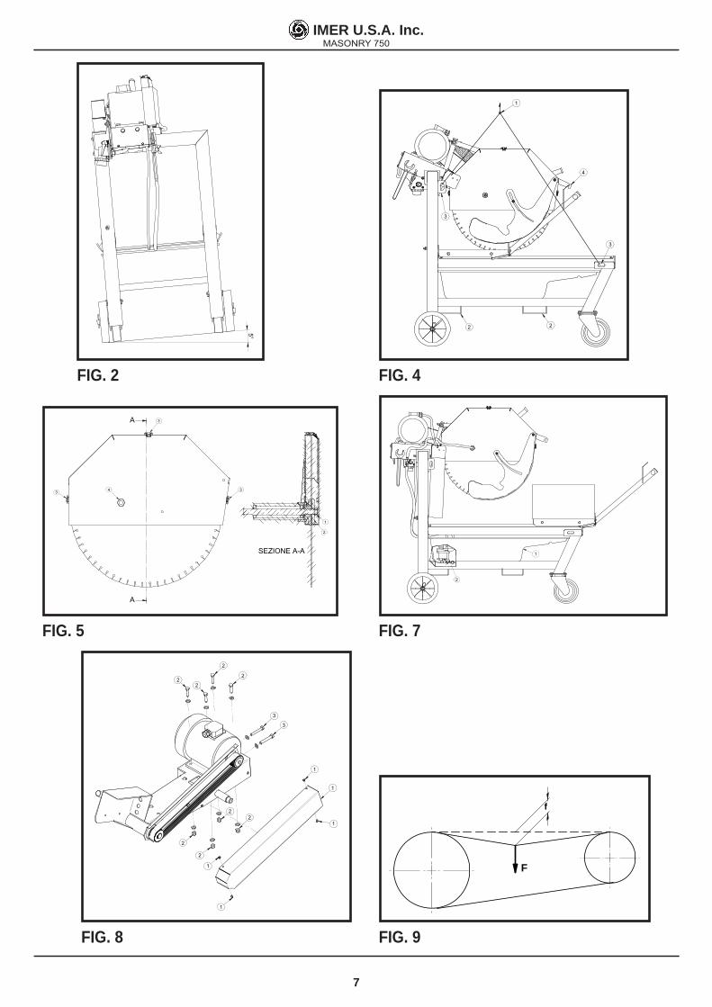
6. WARNING• Do not load the saw with workpieces that exceed the specifi ed weight (max. 40 kg)• Ensure stability of machine: it must be installed on a solid base with a maximum slope of 5° (fi g.2).• The machine is fi tted with a brake on the front castor wheels. Block the wheels with the brake before starting cutting operations.• Ensure the workpiece is stable before, during and after cutting: in any case, workpieces must not overhang the worktable.• Respect the environment; use suitable receptacles for collection of cooling water contaminated with cutting dust.
7. SAFETY PRECAUTIONSIMER saws are designed for work on construction sites and under con-ditions of natural light, hence the workplace must be adequately lit (min 500 lux).
- It must never be used in environments where the danger of explosions and/or fi res exists.
1. IMER saws may only be used when fi tted with all required safety devices, which must be in perfect condition.2. Never use makeshift and/or faulty power cables.3. Make electrical connections on the construction site where they will not be subject to damage. Never stand the saw on power sup-ply cables.4. Lay power cables in such a way as to prevent water penetration. Only use connectors fi tted with water-spray protection (IP67).5. Repairs to electrical installations must only be carried out by qualifi ed technicians. Always ensure that the machine is discon-nected from the power supply and is completely immobile during repairs and maintenance operations.
- The machine should be connected to the site’s equipotential earth system with a copper plait with a minimum cross section of 16 mm2. The connection point is made with a screw welded on the frame (ref.2, fi g.1) and identifi ed with the earth symbol.
- Stop the saw only by means of the main switch (ref.9, fi g.1).
8. ELECTRICAL SAFETYThe IMER saw meets Std. EN 60204-1, EN 61029-1 and is in particular fi tted with:• Protection device against automatic re-start after power failure.• Short-circuit cutout device.• Motor overload cutout switch.

IMER U.S.A. Inc.MASONRY 750
4
9. TRANSPORTATION
- Before removing the panel saw, lock the carriage using the stop (ref.4, fi g.4).
For hoisting the machine use a brace with three arms and (ref.1, fi g.4), inserting the hooks in the special couplings (ref.3, fi g.4). When transpor-ting the machine with a fork lift, insert the left fork in the slot provided (ref.2, fi g.4).As the machine is fi tted on wheels, it can be moved by hand on fl at surfaces as follows:1. make sure that the front wheel brakes are released.2. make sure that the piece holder carriage is clamped with the special ratchet (ref. 4, fi g. 4).3. pull the machine by hand using the piece holder carriage grip; move-ment (also round corners) is facilitated by the front castor wheels.
10. INSTALLATION1. Install the machine on a completely even and stable surface.2. Block the front wheels with the brakes.3. Release the carriage from the lever that secures it to the frame (ref.4, fi g.4).
11. ELECTRICAL MAINS CONNECTION
- Make certain that a residual current device and miniature circuit breaker are installed on the electrical power line.
11.2 Connecting versions with motor 220V/60HzEnsure that the supply voltage corresponds to machine dataplate speci-fi cations. At full load it must be between ***V and ***V.
- To supply the machine it is necessary to use a 3-pole + ground cable in order to ensure the machine's connection to the site's equipotential system.
11.3 Sizing the power supply cableThe power supply line must be suitably sized to prevent voltage drops.Do not use cable winders. The electric cable wire size must take into account the operating currents and length of the line to avoid excessive voltage drops (table 4).
Table 4
Model Type of motorCable (mm²)
1.5 2.5 4.0
Masonry 700 Single-phaseMasonry 700 Three-phase
220 V23.2 A 0 - 12 13 - 24 25 - 50
Cabl
e le
ngth
(m)
220 V22 A 0 - 12 13 - 24 25 - 50
Cables used on construction sites must be fi tted with suitable external sheathing that is resistant to wear, crushing and extreme weather condi-tions (for example H07RN-F).
- All power supply installations must comply with CEI 64-8 standards (harmonised document CENELEC HD384).
12. MACHINE START-UPBefore connecting the machine to the power supply:1. Ensure that the metal structure is connected to an earthing plant as indicated in Section 7 “Safety Precautions”.2. Ensure that the tank contains suffi cient cooling water (min. 60 L; max. 90 L).3. Ensure that the power circuit corresponds to the requirements as in-dicated in Section 11 “Electrical connections”4. Connect the machine to the power supply5. Turn the start-stop selector to the start position (star connection). Wait for 5 sec. and turn to the running position (delta connection).6. Check that the direction of blade rotation corresponds to that indica-ted by the arrow on the blade guard.
- The machine is fi tted with a plug with phase inversion. If the direction of rotation of the disk is the opposite of the arrow on the protective guard, disconnect the power socket from the plug on the machine and invert a phase. To do this, exchange the two mobile terminals on the poles using a screwdriver. This operation is carried out without removing the plug working on the rotary ele-ment that holds the mobile poles.
7. adjust the fl ow of cooling water by turning the cock next to the blade
guard (do not perform cutting without water).8. If all is in order, proceed with cutting.
13. EMERGENCY STOP
- In the case of an emergency, stop the machine pressing the special red mushroom button. To start again, reset the mushroom button turning it clockwise and turn the selector to zero, then re-peat point 12.5 (ref.9, fi g.1).
14. BLADE INSTALLATION1. Slacken the fastener and remove the water pipe (ref. 4, fi g. 5).2.Release the spring catches clamping the disk mobile guard (ref. 3, fi g. 5).3. Slacken the locking nut (ref. 1, fi g. 5) turning it clockwise (left-hand thread).4. Remove the mobile fl ange (ref. 2, fi g. 5). Check that there is no dama-ge on the fl anges, disk shaft and disk.
- Never use worn blades or blades with missing segments.
- Only use blades that are designed for the number of revolu-tions indicated on the machine rating plate.
- Check that the direction of rotation of the disk is as shown on the disk guard.
5. Centre the disk on the fi xed fl ange, position the mobile fl ange (ref. 2, fi g. 5) and tighten the disk locking nut correctly (ref. 1, fi g. 5) turning it counter-clockwise (left-hand thread).6. Refi t the disk mobile guard, hooking the spring catches (ref.3, fi g.5).7. Put the water pipe back in place and tighten the fastener until the pipe is clamped (ref.4, fi g.5).
Fig. 6
- Ensure that the blade guard (ref.3) is locked securely into position.
- An incorrectly installed blade, or a screw insuffi ciently tightened can provoke damage to the machine or injury to persons.
- Note that the blade must have an external diameter of 750 mm, a central hole diameter of 25.4 mm and max. thickness of 4 mm.
- Check that the blade to be used is suitable for the material to be cut.
- Do not use blades for wood (fi g.6).
15. USE
- Leave a space of 150 cm around the machine to operate in full safety.
• Do not allow other persons to approach the machine during cutting.• Never use the machine in fi re-risk areas. Sparks can cause fi re or explosions.• Make sure that the machine is switched off before positioning or han-dling.• Always ensure that the blade is free of any contact before start-up.
- Ensure correct installation of all protective devices.
• Before starting work, fi ll the water tank. Top up during operation whe-never necessary: N.B. the pump suction hose must always remain im-mersed in water.• Insert the plug in the power socket.
- For safety purposes the removal of protective guards from the machine is strictly prohibited.
- The machine is protected against overload: this protection triggers stopping the machine, after which the time necessary for the overload to cool must pass before it is possible to restart the machine.
- To resume work after a voltage cut-off, turn the selector to zero and repeat point 12.5 (ref.9, fi g.1).15.1 Vertical disk movement
- Always switch off the machine before carrying out blade adjustment.

IMER U.S.A. Inc.MASONRY 750
5
To raise or lower the disk, work on the lever (ref.19, fi g.1) until reaching the required height from the cutting table and tighten the clamping lever (ref.17, fi g.1)
- Make sure that the clamping lever is fi rmly tightened before starting to work.
15.2 CuttingFor safe use of the machine when cutting, push the carriage forwards as the cut advances, placing your hands to the two sides of the carriage. Never push directly on the piece to be cut.
- Check that the blade is aligned with the cutting line.
1. Place the workpiece on the worktable (ref.4, fi g.1), resting fi rmly against the stop. 2. Start the engine.3. Wait until the water reaches the blade.4. Begin cutting. 5. Horizontal cutting movement is carried out by pulling the carriage towards the blade.
- As cutting thickness increases, the blade is subjected to greater stress. To avoid overloading the engine, the operator should continually check blade feed speed. The speed will also depend on the characteristics of the material being cut (hardness, toughness etc.).
15.3.1 Cutting downwards from aboveRelease the cutting head working on the clamping lever (ref.17, fi g.1). Position the piece to be cut. Start the sawing machine and start cutting downwards from above working on the head lever (ref.19, fi g.1).
15.3.2 Changing the diskFor changing the disk, please refer to paragraph 4.
16. USING 650 DIAMETER CUTTING WHEEL
A 650 mm diameter cutting disk can be fi tted on the machine. This ope-ration requires adjustment of the cutting head stroke, which is set by the manufacturer for a 750 mm diameter disk. If not carried out properly, this adjustment can damage the machine and cause hazard for persons, it must be carried out by competent and qualifi ed personnel.Proceed as follows:1. Make sure that the machine is disconnected from the power supply.2. Fit the 650 mm diameter disk according to the procedure described in paragraph 14.3. Loosen the bolt (ref.18, fi g.1).4. Lower the cutting head until the disk is in the best cutting position (the disk outside diameter should protrude 15 mm from the cutting surface).5. Turn the cam until locking the cutting head and tighten the bolt.At this point, the cutting head is adjusted for a 650 mm diameter disk.
- To refi t a 750 mm diameter disk, the adjustment should be repeated restoring the original setting. If adjustment is not carried out, the 750 mm disk would interfere with the piece holder carriage structure and damage it with the risk of breakage.
- Note that the blade must have an external diameter of 650 mm, a central hole diameter of 25.4 mm and max. thickness of 4 mm.
17. MAINTENANCE
- Servicing must always be carried out by qualifi ed techni-cians and only after the motor has been switched off.
- Always keep the guards in proper working order and free from damage.Take particular care to ensure that the blade guards are kept effi cient and clean, replacing them if they are damaged.
- As there is the continuous risk of inadvertent damage to the electric cables, these must be checked regularly each time before the machine is used.
In particular, keep the blade guards in effi cient conditions and clean, changing them when damaged.Never leave the machine outdoors: it must be sheltered from the wea-ther.Below is a list of the cleaning operations that must be carried out at the end of every shift.
17.1 Tank cleaningEmpty the tank by removing the drain plug. Remove cutting residue using a jet of water.
17.2 Tank removal (ref.1, fi g.7)Empty the drum opening the drum cap from right or left side.
17.3 Work surface cleaningAlways keep work surfaces clean. Residual dirt can impair cutting pre-cision.
17.4 Guide rail cleaningIt is good practice to remove all traces of dirt from the guides.
17.5 Cleaning and maintenance of cooling circuit
If water does not reach the blade stop the machine immediately to avoid blade damage.After switching off the machine ensure that the water level is suffi cient.If necessary, after disconnecting the machine from the power supply check that the tap, hose and pump fi lter are not blocked
17.6 Tensioning the drive belt1. Switch off the electric motor and remove the plug from the power supply.2. Unscrew the 4 screws that secure the movable belt guard (ref.1, fi g.8).3. Loosen the 4 (ref.2, fi g.8) screws that clamp the electric motor to the blade support.4. Tension the belt using the nut (ref.3): applying a force of about F=6 Kg to the centre of the free section of the belt, the arrow should be about f=6 mm (fi g.9).5. Tighten the screws on the electric motor (ref.2, fi g.8), checking the alignment of the motor pulley and the blade pulley6. Refi t the guard and lock it using the 4 screws (ref.1, fi g.8).
- To avoid shortening the life of the belt, the bearings and the blade shaft, do not overtension the belt. Finally, check the two pul-leys are aligned.
17.7 Changing the drive belt1. Switch off the electric motor and disconnect the plug.2. Slacken the 4 screws fastening the belt mobile guard (ref.1, fi g.8).3. Slacken the 4 screws (ref.2, fi g.8) fastening the electric motor on the disk holder arm.4. Slacken the belt working on the screws (ref.3, fi g.8) and replace it with the new one.5. Pull the belt working on the screws (ref.3, fi g.8): if the belt tension is correct, applying a force of approx. F=6 Kg at the centre of the free section of belt, the camber should be approx. f=6 mm (fi g.9).6. Tighten the electric motor screws (ref.2, fi g.8), checking the alignment of the motor pulley and that of the disk.7. Refi t the belt guard and lock it with the 4 screws (ref.1, fi g.8).
17.8 Repairs
- Before carrying out any maintenance operations, switch off the machine, and remove the plug from the power socket.
- If the guards are removed to carry out repairs, they must be refi tted properly when the repair work is fi nished.
Only use genuine IMER spare parts and do not modify them.

IMER U.S.A. Inc.MASONRY 750
6
18. RESIDUAL RISKS AND SAFETY SIGNSAlthough the sawing machine has been manufactured fully in complian-ce with current regulations, residual risks exist that cannot be eliminated and involve the use of appropriate individual protection devices. Ade-quate warning signs fi tted on the machine point out both the risks and the behaviour to be followed.
NOISE RISK
Ear protection must be worn
RISK OF INJURY TO THE HANDS
Safety gloves must be worn
RISK OF INJURY TO THE EYES
Eye protection must be worn
ABNORMAL USE RISK
Reading the manual before use is compulsory
Cutting with water is compulsory
RISK OF DRAGGING, ABRASION AND CUTTING
Do not remove the guards
Do not touch transmission components
Danger cutoff
RISK OF ELECTROCUTION
Danger electricity
Please be reminded that checking the use of IPDs is delegated to the employer.
19. TROUBLESHOOTING
- CAUTION!!! All maintenance operations must be performed exclusively with the machine switched off, with the selector set to “0” and the power plug disconnected from the mains.
Fault Cause Remedy
Motor does not start when switch is turned
Defective power cable Check power cables *
Plug not inserted in socket correctly
Ensure correct connection
Power cable from plug to control panel detached
Remake the connection *
Loose wire inside motor circuit board
Remake the connection *
A wire has become disconnected inside the panel
Remake the connection *
Faulty main switch Replace switchA fuse has blown Replace the fuse *The overload safety device has been activated
Wait for a few minutes and then try restarting the machine
Horizontal carriage movement not smooth
Guide rails dirty Clean the guide rails
Lack of cooling water supply to blade
Refer to section "cleaning and maintenance of cooling circuit" (chapter 17.5)
Blade does not cutBlade is worn Fit new bladeDrive belt not tensioned Tension the belt
Motor starts but blade does not rotate
Belt is broken Replace drive belt
* Operation to be carried out by an electrician
IMER U.S.A. Inc.MASONRY 750
7
5°
1
3
3
2 2
4
FIG. 2 FIG. 4
A
A
SEZIONE A-A
3
3
3
1
2
4
2
1
FIG. 5 FIG. 7
1
1
1
1
1
2
2
22
3
3
2
2
22
F
f
FIG. 8 FIG. 9

IMER U.S.A. Inc.MASONRY 750
8
2
116
7
9
10
11
12
13
14 16
17
18
22
23
24
25
107
28
30
106
38
39
45
37
51
55
56
67
68
69 70
71
72
73
74
75
76
77
82
83
84
86
87
88
89
90
91
9394 95
96
57
103
104
5
40
101
44
99
1
117
64
102
36
63
97
98
85
17
116
1010
10
11
12
13
13 13
15
16
17
17
17
17
17
17
1717
17
18
18
18
1818
18
18
23
24
24
24
2525
25
25
25
65
25
25
2525
28
2828
2828
28
28
28
28
28
28
28
28
28
28
28
28
28
30
2828
2828
30
30
51
51
54
54
55
59
60
6767
67
67
6767
67
67
67
6767 67
67
121
76
78
81
66
95
64
64
64
64
64
6464
63
80
17
17
17
1321
62
4
4
34
34
1313
13
13
2525
2525
28
28 2828
2828
2828 10
0
26
26
2626
32
32
3232
6
58
58
58
58
61
13
13
13
21
2121
79
110
112
113
66
20
2020
20
21
2330
31
53
105
108 10
9
111
2528
64
64
2828
4343
43
43
505065
82
114
115
115
2528
92
2129
29
35
51
13
1313
13
25
25
2525
28
28
28
2828
28 2828
100
52
42
41
48
49
46
47
19
8
27
33
8
8
26
26
26
26
27
27
32
32
3232
33
58
5858
58
3
3
3
34
34
118
119
120
120

IMER U.S.A. Inc.MASONRY 750
9
TAV.1 - MACHINE STRUCTUREREF. CODE DESCRIPTION NOTES
1 1207088 OIL SEAL RING ADT D.45X62X82 1224113 WASHER D.10X50X3 Z3 1283984 NUT PG 214 2211150 WHEEL5 2213840 FORK 1676 M12X62 Z6 2218075 VALVE7 2222007 BOLT TE 8.8 5739 M12X35 Z8 3231012 HANDWHEEL 4 LOBES M69 2222036 BOLT TE 8.8 5739 M12X40 Z
10 2222050 BOLT TE 8.8 5739 M12X45 Z11 2222054 BOLT TE 8.8 5739 M12X80 Z12 2222073 BOLT TE 8.8 5739 M10X35 Z13 2222076 BOLT TE 8.8 5739 M8X25 Z14 2222077 BOLT TE 8.8 5739 M10X20 Z15 2222110 BOLT TE 8.8 5737 M8X80 Z16 2222176 BOLT TE 8.8 5737 M8X50 Z17 2222420 BOLT AUT. TE 6950 D.4,8X13 Z18 2222430 BOLT AUTOF. TC 7971 4.8X9.519 2222449 BOLT AUTOF. TC 6954 3.5X1920 2222530 BOLT TCEI 5931 M8X35 Z21 2223570 NUT 5588 M8 Z22 2223700 NUT 5588 M12 Z23 2223920 SELF LOCKING NUT AUTOBL. M10 747424 2223921 SELF LOCKING NUT AUTOBL. M12 747425 2223923 SELF LOCKING NUT AUTOBL. M8 747326 2223927 SELF LOCKING NUT AUTOBL. M527 2224006 THREADED INSERT28 2224140 WASHER 6593 D.8X18 Z29 2224204 WASHER 6593 D.8X24 Z30 2224340 WASHER 6592 D.10X21 Z31 2224430 WASHER 6593 D.14X36 Z32 2224528 WASHER D.5X15 Z33 2224531 WASHER D.6X18 Z34 2226700 SPLIT PIN 35 2226778 ELBOWN F.3/8" D.10 RO15036 2227240 OIL SEAL RING 7435 E/3037 2227300 OIL SEAL RING 3653 E/2838 2228738 PIN 1707 D.10X1439 2229350 KEY 8X7X3540 2230550 GREASER 1/8 DIRITTO SGS - 19641 2235428 CONICAL CAP42 2241574 KEY43 2288810 RIVET44 2288887 KNOB45 2292355 Y DEVIATION46 2292356 ANTI-FREEZE HOOSE47 2292356 ANTI-FREEZE HOOSE48 2292365 ANTI-FREEZE HOOSE49 2292365 ANTI-FREEZE HOOSE50 3201163 NUT 5589 M1851 3201503 CABLE CLAMP HSK-K PG2152 3203921 BOLT TC PH M5X10 N53 3204420 CAP54 3204945 BEARING 608 2RS155 3206079 KNOB56 3206722 KEY 8X7X3057 3231011 HANDWHEEL 3 LOBES M12X4058 3207152 BOLT TCB 7687 M5X2059 3207393 SPACER BRACKET60 3207397 WHEEL61 3208455 BOLT TTDE M10X35 5732 Z62 3208726 WATER PUMP63 3210411 SPACER BRACKET64 3210576 WASHER D.8.4X17X1.565 3210623 SELF LOCKING NUT M8 747466 3210646 CAP67 3211038 WASHER 6592 D.13X24 Z
TAV.1 - MACHINE STRUCTUREREF. CODE DESCRIPTION NOTES68 3224476 FRAME69 3231297 HEAD GROUP70 3224482 BLADE SHAFT71 3231339 INNER FLANGE72 3231340 OUTER FLANGE
73 32244863230340 PULLEY THREE-PHASE
SINGLE-PHASE74 3231285 DISC COVER75 3231286 GUARD76 3224514 PLATE77 3224565 SPACER BRACKET78 3224566 SPACER BRACKET79 3224604 CARRIAGE80 3224626 BOLT TTCQ 5732-65 M8X25 Z81 3224680 SPACER BRACKET82 3224705 GUIDE BAR83 3224740 GUARD84 3224741 GUARD85 3224814 CAP86 3225043 PROTECTION87 3225543 HANDGRIP
88 3225548 BLADE GUARD ROTATION ROD
89 3231301 MOTOR PULL PLATE
90 32281243230332 JUNCTION BOX THREE-PHASE
SINGLE-PHASE
91 32281233230330 MOTOR THREE-PHASE
SINGLE-PHASE92 3225564 BELT93 3225642 DRUM94 3231302 CAM95 3225956 SPACER96 3225984 PLUG97 3225993 SUPPORT98 3225994 SUPPORT99 3225996 SPRING
100 3225997 WHEEL101 3226001 HANDGRIP102 3226002 WASHER PS 13X19X1
103 3226003 FRONT HEAD PROTECTION CASING
104 3226004 REAR HEAD PROTECTION CASING
105 3231295 SPLASHGUARD SUPPORT
106 3226015 OIL SEAL RING 7435 E/75107 3226028 NUT 5589 M24X2 SIN Z108 3226034 SPACER BRACKET109 3226035 SPACER BRACKET
110 3231291 CUTTING WHEEL RH GUARD
111 3231290 CUTTING WHEEL LH GUARD
112 3226039 TROLLEY CLAMPING113 3226040 BOLT TE 8.8 5737 M18X200 Z114 3231305 REAR SPLASHGUARD115 3231296 PLATE116 3226506 BEARING THREE-PHASE
117 32281253230465 PLUG THREE-PHASE
SINGLE-PHASE118 3228471 RH SPLASHGUARD OPTIONAL119 3228472 LH SPLASHGUARD OPTIONAL
120 3228543 SIDE SPLASHGUARD SUPPORT OPTIONAL
121 32244863230342 PULLEY THREE-PHASE
SINGLE-PHASE122 3210448 CAPACITOR 60 μF

IMER U.S.A. Inc.MASONRY 750
10
TAV.2 3230332 ELECTRIC PANEL SINGLE PHASE
RIF. COD.1 3231665 ELECTRIC BOX2 3207920 EMERGENCY BUTTON3 3201503 CABLE CLAMP PG214 3201442 CABLE CLAMP PG165 3201217 CABLE CLAMP PG116 3207922 MAGNETOTHERMAL 20-25A7 3207924 NO-VOLT COIL8 3227742 FUSEHOLDER9 3227783 FUSE
I1
F1-F2
3
1
25
4
6
7
8
9
TAV.2
MOBILE SOCKET
CODE 3230464 230V 2P+TSPH

IMER U.S.A. Inc.MASONRY 750
11
TAV.3 3233959 ELECTRIC PANEL 230V 50Hz TPHREF. CODE DESCRIPTION
1 3231345 ELECTRIC BOX2 3207920 EMERGENCY BUTTON3 3226298 STAR-TRIANGLE SWITCH4 3201503 CABLE CLAMP PG215 3201442 CABLE CLAMP PG166 3201217 CABLE CLAMP PG117 3207922 MAGNETOTHERMAL 20-25A8 3207924 NO-VOLT COIL9 3207971 CONTACT
10 3227742 FUSEHOLDER11 3227783 FUSE
MOBILE SOCKET
CODE 3228456 230V 3P+TTPH
V
Y0
I1
F1-F2
4
1
2
36
5
7
89
10
11
I RCD
I1
1 3 5642
U<
I1
531
2 4 6
97
8 10
0YV
11
12
13
14
15
16
17
18
R S T
1
3
U Z V X W
Y
(3)
(2)
(1)
(4)
(5)
(6)
33
34
PETSR
PE
U1 V1 W1 U2 V2 W2 PE
PE N L1
(BROWN)
(BLACK)
(BR
OW
N)
(3 - WHITE)
(1 -
WH
ITE
)
(2 -
BIA
NC
O)
R (B
RO
WN
)
S (B
LAC
K)
T (B
LUE
)
H07RN-F4G2,5 mmq.
2,5 mmq.
MOVABLE PLUGCEE 3P+T 32A h3PROTECT. IP67
IG1START SWITCH
H07RN-F7G2,5 mmq.
MAIN MOTOR 5,5Kw
220V 22A
380V 12,5A
2,5 mmq.
F1-26,3x32 1 A
3G1 mmq.
WATER PUMP230V - 60W
9-10
11-12
7-8
5-6
1-2
3-4
SWITCH IG1
0 Y
V
13-14
17-18
15-16
NOTE: The motor protection mustbe calibratet on 17A
LEGEND:Id - RCD FROM 30mA (OPTIONAL EXERNAL FRAME)I1 - Motor protection switch 16-20AI1 - Aux contact (33-34) 1no+1ncU< - no-volt coil 230VIG1 - star-triangle start switch 32AF1 - Fuseholder 6,3x32 with fuse from 1A 500V
Numerooggetto
16151413121110
1
*
7
432
65
89
**
*
F2 - Fuseholder 6,3x32 with fuse from 1A 500V
Motor protectionswitch 20-25A
3233959-ELECTRIC CONTROL PANEL 230V-50Hz TPH
TAV.3

IMER U.S.A. Inc.MASONRY 750
12

IMER U.S.A. Inc.MASONRY 750
13
ONE YEAR WARRANTYWe warrant to the original purchaser that the IMER equipment described herein (the "equi-pment") shall be free from defects in material and workmanship under normal use and service for which it was intended for a period of one (1) year from the date of purchase by the original purchaser.
Our obbligation under this warranty is expressely limited to replacing or repairing, free of charge, F.O.B. our designated service facility, such part or parts of the equipment as our inspection shall disclose to be defective. Parts such as engines, motors, pumps, valves, electric motors, etc. furnished by us but not manifactured by us will carry only the warranty of the manifacturer. Transportation charges or duties shall be borne by the purchaser. This shall be the limit of our liability with respect to the quality of the equipment.
This warranty shall not apply to any equipment, or parts thereof, which has been damaged by reason of accident, negligence, unreasonable use, faulty repairs, or which has not been mantained and operated in accordance with our printed instructions for our equipment. Further, this warranty is void if the equipment, or any of its components, is altered or modi-fi ed in any way.
THIS WARRANTY IS EXPRESSLY IN LIEU OF ALL OTHER WARRANTIES, EXPRES-SED OR IMPLIED, INCLUDING ANY IMPLIED WARRANTY OF MERCHANTABILITY OF FITNESS FOR A PARTICULAR PURPOSE.
We make no other warranty, representation or guarantee, nor is anyone authorized to make one on our behalf. We shall not be liable for any consequential damage of any kind, including loss or damage resulting, directly or indirectly, from the use or loss of use of the machine. Without limiting the generality of the foregoing, this exclusion from liability em-braces the purchase's expenses for downtime, damages for which the purchaser may be liable to other persons, damages to property, and injury or death of any persons.
This warranty shall not be deemed to cover maintenance parts, including but not limited to blades, belts, hoses, hydraulic oil or fi lters, for which we shall have no responsability or liability whatsoever.
IMER U.S.A. Inc.221 Westhampton Place
Capitol Heights, MD 20743Ph. 301.336.3700Fax 301.336.6687
Toll Free: [email protected]