3.1m commercial antenna az-el fixed mount az-el-fixed.pdf · 3.1m commercial antenna az-el fixed...
TRANSCRIPT
INSTALLATION &ASSEMBLY INSTRUCTIONS
3.1m Commercial AntennaAz-El Fixed Mount
ANTENNA SYSTEMS
2
This PATRIOT ANTENNA equipment is warranted to be free from defects in material and workmanship undernormal use and service. PATRIOT ANTENNA shall repair or replace defective equipment, at no charge, or at itsoption, refund the purchase price, if the equipment is returned to PATRIOT ANTENNA not more than twelve (12)months after shipment. Removal or reinstallation of equipment and its transportation shall not be at cost of PA-TRIOT ANTENNA except PATRIOT ANTENNA shall return repaired or replaced equipment freight prepaid.
This Warranty shall not apply to equipment which has been repaired or altered in any way so as to affect itsstability or durability, or which has been subject to misuse, negligence or accident. This Warranty does not coverequipment which has been impaired by severe weather conditions such as excessive wind, ice, storms, lightning,or other natural occurrences over which PATRIOT ANTENNA has no control, and this Warranty shall not apply toequipment which has been operated or installed other than in accordance with the instructions furnished byPATRIOT ANTENNA.
Claimants under this Warranty shall present their claims along with the defective equipment to PATRIOT ANTENNAimmediately upon failure. Non-compliance with any part of this claim procedure may invalidate this warranty inwhole or in part.
THIS WARRANTY IS EXPRESSLY IN LIEU OF ALL OTHER AGREEMENTS AND WARRANTIES, ANY IMPLIEDWARRANTY OF MERCHANTABILITY OR FITNESS FOR A PARTICULAR PURPOSE IS LIMITED IN DURATIONTO THE DURATION OF THIS WARRANTY. PATRIOT ANTENNA DOES NOT AUTHORIZE ANY PERSON TOASSUME FOR IT THE OBLIGATIONS CONTAINED IN THIS WARRANTY AND PATRIOT ANTENNA NEITHERASSUMES NOR AUTHORIZES ANY REPRESENTATIVE OR OTHER PERSON TO ASSUME FOR IT ANYOTHER LIABILITY IN CONNECTION WITH THE EQUIPMENT DELIVERED OR PROVIDED.
IN NO EVENT SHALL PATRIOT ANTENNA BE LIABLE FOR ANY LOSS OF PROFITS, LOSS OF USE, INTER-RUPTION OF BUSINESS, OR INDIRECT, SPECIAL OR CONSEQUENTIAL DAMAGES OF ANY KIND.
In no event shall PATRIOT ANTENNA be liable for damages in an amount greater than the purchase price of theequipment.
Some states do not allow limitations on how long an implied warranty lasts, or allow the exclusion or limitation ofincidental or consequential damages, so the above limitations or exclusions may not apply to you.
PATRIOT ANTENNA has the right to void the warranty when the antenna is installed by someone other then acertified installer.
LIMITED TWELVE (12) MONTH WARRANTY
Patriot Antenna Systems704 North Clark StreetAlbion, MI 49224 USA Tel: (517)629-5990Fax: (517)629-6690
E-mail: [email protected]
Product Serial Number- _________________Date Purchased- ____________
3
Thank you for purchasing your Patriot Commercial Antenna. We trust that you will findthis to be a well designed product that will provide many years of reliable service.This manual will help you to know the tools and proper installation of the product.Please check, read and understand the content of this manual before beginning yourantenna installation.
Identify and verify that all parts have been received by comparing packaged contentswith the Hardware List below.
Record the serial number of the unit on page 2 for future reference and read thewarranty information. The serial number can be found on the antenna hub.
2– Adjustable wrenches (12” or larger)1– Drive Socket set (through 3/4”)2– 15/16” combination wrenches1– Combination wrench set through 3/4”2- pocket aprons for hardware, tools
Hardware Table
Tools Required
Other
1- Pre-installed 51/2” OD Inground Mast (not included)
1- 8’ step ladder1- allen socket set1- level1- tape measure1-Cordless Drill with 5/32” Allen Head attatchment
No.__Description Qty_1 3.1m Radial Beams 82 3.1m Petals 83 3.1m Ourboard Skirts 84 3.1m Hub Assembly 15 Az-El Mount Assembly 16 Upper Pivot Block Assembly 17 Elevation Adjustmen Rod 18 3.1m Feed Struts 49 C-Band Feed plate 110 Feed Cover 1
No.___Description____ _____ Qty_11 Radial Beam pack 112 Hub to Mount pack 113 Reflector & Feed pack 114 Extra Hardware pack 1
*We include 1 can of matching touch-up paintfor your convenience.
4
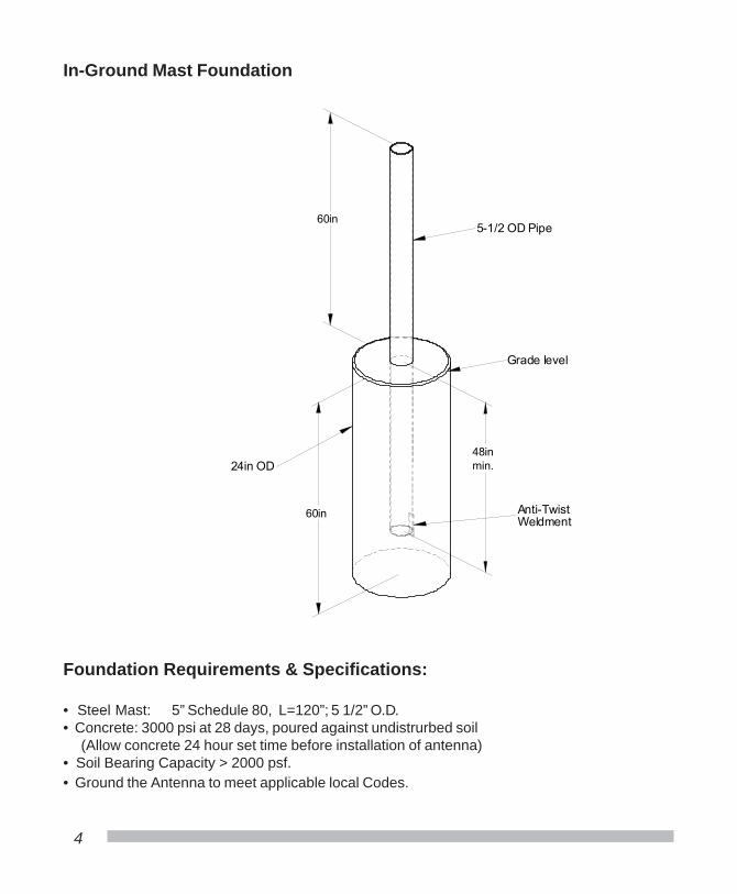
In-Ground Mast Foundation
Foundation Requirements & Specifications:
• Steel Mast: 5” Schedule 80, L=120”; 5 1/2” O.D.• Concrete: 3000 psi at 28 days, poured against undistrurbed soil (Allow concrete 24 hour set time before installation of antenna)• Soil Bearing Capacity > 2000 psf.• Ground the Antenna to meet applicable local Codes.
60in
min.48in
60in
5-1/2 OD Pipe
24in OD
Anti-TwistWeldment
Grade level
5
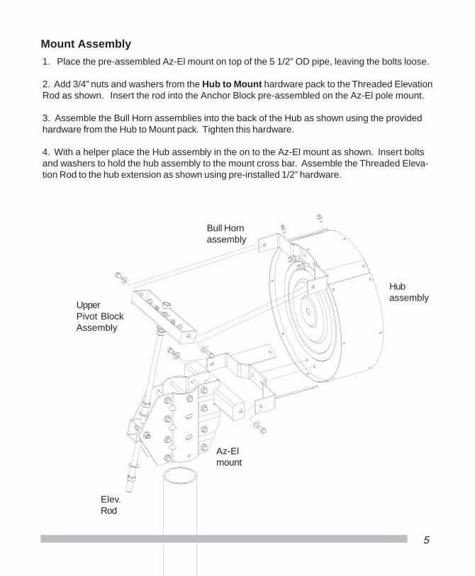
Mount Assembly
1. Place the pre-assembled Az-El mount on top of the 5 1/2” OD pipe, leaving the bolts loose.
2. Add 3/4” nuts and washers from the Hub to Mount hardware pack to the Threaded ElevationRod as shown. Insert the rod into the Anchor Block pre-assembled on the Az-El pole mount.
3. Assemble the Bull Horn assemblies into the back of the Hub as shown using the providedhardware from the Hub to Mount pack. Tighten this hardware.
4. With a helper place the Hub assembly in the on to the Az-El mount as shown. Insert boltsand washers to hold the hub assembly to the mount cross bar. Assemble the Threaded Eleva-tion Rod to the hub extension as shown using pre-installed 1/2” hardware.
Hubassembly
Az-Elmount
Elev.Rod
Bull Hornassembly
UpperPivot BlockAssembly
6
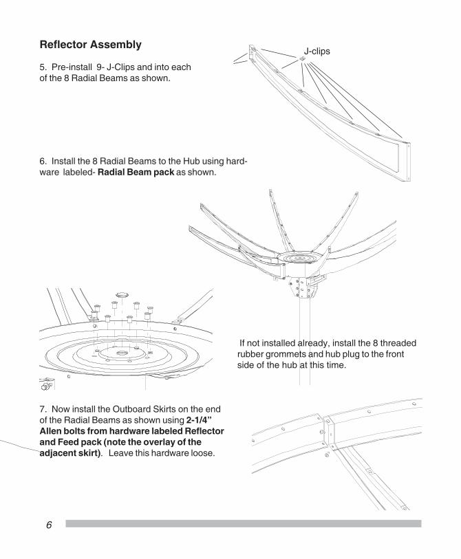
Reflector Assembly
5. Pre-install 9- J-Clips and into eachof the 8 Radial Beams as shown.
6. Install the 8 Radial Beams to the Hub using hard-ware labeled- Radial Beam pack as shown.
J-clips
7. Now install the Outboard Skirts on the endof the Radial Beams as shown using 2-1/4”Allen bolts from hardware labeled Reflectorand Feed pack (note the overlay of theadjacent skirt). Leave this hardware loose.
If not installed already, install the 8 threadedrubber grommets and hub plug to the frontside of the hub at this time.

7
8. Install Anenna Panels noting overlay of joining edge. Join 2 panels to one Radial Beamusing 1/4” Allen Bolts from the Reflector and Feed pack. Work out from the hub (note edgeoverlay should be even) Tighten the hardware into each J-clip after all hardware is in place.
9. Install 48- 1/4” Allen bolts with flange nuts to Antenna Panel perimeter edge and OutboardSkirts tightening them as they are installed.
10. Tighten all Reflector hardware at this time.
8
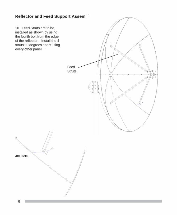
Reflector and Feed Support Assembly
10. Feed Struts are to beinstalled as shown by usingthe fourth bolt from the edgeof the reflector . Install the 4struts 90 degrees apart usingevery other panel.
FeedStruts
4th Hole
9
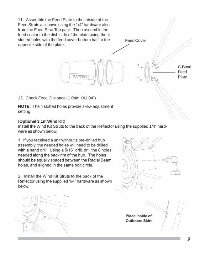
11. Assemble the Feed Plate to the intside of theFeed Struts as shown using the 1/4” hardware alsofrom the Feed Strut Top pack. Then assemble thefeed scalar to the dish side of the plate using the 4slotted holes with the feed cover bottom half to theopposite side of the plate.
NOTE: The 4 slotted holes provide skew adjustmentsetting.
12. Check Focal Distance- 1.04m (41.04”)
Feed Cover
C-BandFeedPlate
(Optional 3.1m Wind Kit)Install the Wind Kit Struts to the back of the Reflector using the supplied 1/4” hard-ware as shown below.
2. Install the Wind Kit Struts to the back of theReflector using the supplied 1/4” hardware as shownbelow.
Place inside ofOutboard Skirt
1. If you received a unit without a pre-drilled hubassembly, the needed holes will need to be drilledwith a hand drill. Using a 5/16” drill, drill the 8 holesneeded along the back rim of the hub. The holesshould be equally spaced between the Radial Beamholes, and aligned in the same bolt circle.
10
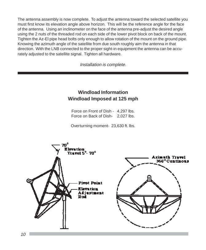
Windload InformationWindload Imposed at 125 mph
Force on Front of Dish - 4,297 lbs.Force on Back of Dish- 2,027 lbs.
Overturning moment- 23,630 ft. lbs.
The antenna assembly is now complete. To adjust the antenna toward the selected satellite youmust first know its elevation angle above horizon. This will be the reference angle for the faceof the antenna. Using an inclinometer on the face of the antenna pre-adjust the desired angleusing the 2 nuts of the threaded rod on each side of the lower pivot block on back of the mount.Tighten the Az-El pipe head bolts only enough to allow rotation of the mount on the ground pipe.Knowing the azimuth angle of the satellite from due south roughly aim the antenna in thatdirection. With the LNB connected to the proper sight-in equipment the antenna can be accu-rately adjusted to the satellite signal. Tighten all hardware.
Installation is complete.

Equipment From The Industry’s Lead-ing Satellite Equipment Manufacturer’s
Available Together - In One Place...
We are Cal-Amp’s LARGESTSTOCKING DISTRIBUTOR!
No Long Lead Times...No Drop Ship Fees...
High Inventory...Great Prices...
Complete line of Quality Feedhorns,Receivers and Accessories - from aname you trust
W e A l s o O f f e r P r o d u c t s f r o m t h e f o l l o w i n g :
Durable Snow Covers for CommercialAntennas as well as Home System -Keep snow from interfering with yoursignal.
Prevent Snow & Ice from accumlulatingon your system with a De-Icing System.
Complete line of Antenna Controllers,Positioners and Software for yourmotorized applications.
Looking to increase yoursatellite’s reception? Tryupgrading your feedsystem to a Multi-BeamFeed. Receive up to 4simultaneous satellites
Products Also Avaliable from:
Offset VSAT& DBS Antennas Available!
• ADL• General Instruments• Baird • Norsat• Drake • Standard Comm• DX • Thomson-Saginaw• Force • Wegner
Toll Free 1-800-470-3510
11
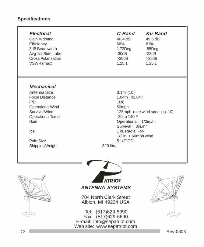
Specifications
Electrical C-Band Ku-BandGain Midband 40.4 dBi 49.6 dBiEfficiency 66% 61%3dB Beamwidth 1.72Deg .55DegAvg 1st Side Lobe -30dB -23dBCross Polarization >35dB >35dBVSWR (max) 1.25:1 1.25:1
MechanicalAntenna Size 3.1m (10’)Focal Distance 1.04m (41.04”)F/D .336Operational Wind 50mphSurvival Wind 125mph (see wind spec. pg. 10)Operational Temp -20 to 140 FRain Operational = 1/2in./hr
Survival = 3in./hrIce 1 in. Radial -or-
1/2 in. + 60mph windPole Size 5 1/2” ODShipping Weight 320 lbs.
12 Rev-0803
ANTENNA SYSTEMS
704 North Clark StreetAlbion, MI 49224 USA
Tel: (517)629-5990Fax: (517)629-6690
E-mail: [email protected] site: www.sepatriot.com