3127-i-hd-003-a.pdf
TRANSCRIPT

8/10/2019 3127-I-HD-003-A.pdf
http://slidepdf.com/reader/full/3127-i-hd-003-apdf 1/15
REV: A Sh..: 1Of: 15
AST N 3127-I-HD-003 REV: A
CLIENT: TRANSIERRA S.AJOB: GASYRG ESTACION DE COMPRESION VILLAMONTES
JOB N : 3127
DATA SHEET
CONTROL VALVES
A 29-4-2003 ISSUE FOR CONSTRUCTION DP OS GN0 14-1-2003 ISSUE FOR APPROVAL DP OS GN
REV. DATE DESCRIPTION BY CHKD. APPROVAL
TSR N : E-FD-7010.00-6240-800-AEV-003

8/10/2019 3127-I-HD-003-A.pdf
http://slidepdf.com/reader/full/3127-i-hd-003-apdf 2/15
Rev.: A Sh.: 2
Of: 15
CLIENT: TRANSIERRA S.A.JOB: GASYRG ESTACION DE COMPRESION VILLAMONTES
SERVICE LOCATION P&IDMANUFACTURER /
MODEL
SHEET NOTES
LV - 016 FT-0201 DRAIN Skid 0201 3127-F-PI-009 Fisher / 357 (1") 3
LV - 017 FT-0201 DRAIN Skid 0201 3127-F-PI-009 Fisher / 357 (1") 4
LV - 022 FT-0202 DRAIN Skid 0202 3127-F-PI-009 Fisher / 357 (1") 5
LV - 023 FT-0202 DRAIN Skid 0202 3127-F-PI-009 Fisher / 357 (1") 6
TV - 106A Fuel gas heater Skid 0205 3127-F-PI-013 Fisher / YD (3") 7
TV - 106B Fuel gas heater Skid 0205 3127-F-PI-013 Fisher / YD (3") 8
PV - 107A Fuel gas to TC Skid 0205 3127-F-PI-014 Fisher / ET (2") 9
PV - 107B Fuel gas to TC Skid 0205 3127-F-PI-014 Fisher / ET (2") 10
PV - 109 Start up gas to TC Skid 0205 3127-F-PI-014 Fisher / ET (2") 11
TV - 175A Fuel gas to MG Skid 0204 3127-F-PI-019 Fisher / YD (1") 12
TV - 175B Fuel gas to MG Skid 0204 3127-F-PI-019 Fisher / YD (1") 13PV - 181A Gas to MG fuel gas filter Skid 0204 3127-F-PI-009 Fisher / 357 (2") 14
PV - 181B Gas to MG fuel gas filter Skid 0204 3127-F-PI-009 Fisher / 357 (2") 15 New
Ambient temperatures:Minimum: 10,4 CNormal: 25,2 CMaximum:40 C
1) Not only the valve but also actuators shall be supplied with their TAGS engraved on a nameplate.
TSR N : E-FD-7010.00-6240-800-AEV-003
AST N : 3127-I-HD-003
CONTROL VALVE LIST
1. P&IDs
N ! TAG
References:
3127-F-PI-009 a 022 Rev B
Notes:
2) Solenoide valve will be suitable for Zone 2 Gr IIA T3, IP55, provided with terminal block. Lowpower solenoids must be employed. The insulation class of solenoid valves coils must beselected in accordance with environmental temperature and the temperature raise in thesolenoid itself (minimum class F). The use of Solenoid valves with manual return handle mustbe avoided.
3) All tubing and fitting for connecting the additional equipment and actuator shall be integralpart of valve vendor ! s supply. Tubing and fitting shall be stainless steel (AISI 316). Fitting shallbe double ferrule type.
A
3127-I-HD-003-A.xls

8/10/2019 3127-I-HD-003-A.pdf
http://slidepdf.com/reader/full/3127-i-hd-003-apdf 3/15
153TRANSIERRAEST. COMPRESION VILLAMONTES
LV -016
3127-I-HD-003FT-0201 DRAIN
Hidrocarbon
751371.69 100
1 0C 47.3
kg/m " 751.3 751.3cP 0.829 0.829
72.692.9689
< 85
751.32
2 in 80 Spring & Diaphragm2 80 FISHER 357/40
NoneSingle Seat Globe On/Off
1 in ANSI 600 CloseC
FISHER 357 (1")WCC Carbon STL Cast
9 kgf/cm # -g 4.5RF FLGRF FLG
None
Down Tubing and fitting in S Steel4-20 mA DCI/P converter
PTFE FISHER 646
MFR STD IncreasesSupply & OutputMFR STD3/8 in in Mounting on actuator
M-Form (=%)Unbalanced
3.5317-4 PH/CERAM
Ceramic17-4 PH H1150 FISHER 67CFR
316 SSTYES YES
Area classification Zone 2 Gr IIA A low power explosion-proof solenoid
ANSI IV (standard)
valve shall be supplied for this valve
0.829
24 VDC and 1/2" NPT cable entryModel 8314EFG300
Valves must be supplied with a stainless steel label engraved with the respective TAG number, valve model, manufacturer, diameter,Cv, etc.
kgf/cm # -gkg/h
kgf/cm # -gNorm. Flow Min. Flow
* MFR & ModelMax Press/Temp
Lube
Units
DATA SHEETLINETAGDWGSERVICE
of
* MFR SERIAL
P. O.ITEMCONTRACT
PROJECTUNIT
9101112
1
23
45678
131415
Flow RateInlet Pressure
Outlet PressureInlet TemperatureDensity / Spec. Grav. / Mol. Wt / Z
Process Fluid Crit Press PC
Viscosity / Specific Heats Ratio
16
17
20
1819
212223242526272829
303132
Pipe Line Size
Pipe Line Insulation & Schedule
INE
L
* Type
* Size ANSI Class
//
* Body/Bonnet Matl* Liner Material / ID /
3334353637383940
InOut
InOutConnection
End
End Ext / MaterialFlg Face Finish
* Flow Direction* Type of BonnetLub & Iso Valve
C
VRE
E
I
S
OND
C
I
ONS
I
T
A0Rev. Date Description
525150494847464544434241
* Size
* Packing Material
* Packing Type
* TypeRated Travel
* Characteristic* Balanced / Unbalanced
* Seat Material* Cage / Guide Material* Stem Material
Cv/Cg
M
RT
I
* Rated FL XT
YDOB
/
BO
T
NN
E
I
SL
A
/
CEP
A
ROS
I
CC
ES
ES
S
676869
7071727374757677787980
Orig.
838281
868584
08/01/200329/04/2003
Issue for approvalIssue for construction
DPDP
App.
* Information supplied by manufacturer ISA Form S20.50, Rev. 1
E
V
VL
A
Input Signal
Quantity
/
On/Off
Spring Action Open/Close* Max Allowable Pressure* Min Required Pressure
Available Air Supply Pressure
* Size
Max Min* Bench Range
Actuator OrientationHandwheel Type
Air Failure Valve Set at
* Type* MFR & Model
OSI
P
Gauges
Eff AreaModulating
Bypass* Cam Characteristic
* On Incr Signal Output Incr/Decr
* Type* MFR & Model /
Type
Contacts / Rating Actuation Points
IONER
T
Filter Gauge
* MFR & Model /
/
TES
RI
A
TCH
SWI
S
TEST
* MFR & Model* Set Pressure
* Hydro ANSI/FCI Leakage Class
ISA CONTROL VALVES II DATA SHEET
Max. Flow
kgf/cm # -g
kgf/cm # -g
53545556
57585960616263646566
TC
A
ROT
AU
Shut-Off
Inlet Vapour Pressure* Required Cv / Cg* Travel
Allowable / * Predicted dBA%
kgf/cm # -a
in
kgf/cm # -g
/ / /
* Plug/ Ball/ Disk Material
/
Notes:
P&ID 3127-F-PI-009
2"-HC-7010.02-027-YN100

8/10/2019 3127-I-HD-003-A.pdf
http://slidepdf.com/reader/full/3127-i-hd-003-apdf 4/15
154TRANSIERRAEST. COMPRESION VILLAMONTES
LV -017
3127-I-HD-003FT-0201 DRAIN
Hidrocarbon
751371.69 100
1 0C 47.3
kg/m " 751.3 751.3cP 0.829 0.829
72.692.9689
< 85
751.32
2 in 80 Spring & Diaphragm2 80 FISHER 357/40
NoneSingle Seat Globe On/Off
1 in ANSI 600 CloseC
FISHER 357 (1")WCC Carbon STL Cast
9 kgf/cm # -g 4.5RF FLGRF FLG
None
Down Tubing and fitting in S Steel4-20 mA DCI/P converter
PTFE FISHER 646
MFR STD IncreasesSupply & OutputMFR STD3/8 in in Mounting on actuator
M-Form (=%)Unbalanced
3.5317-4PH/CERAM
CERAMIC17-4PH H1150 Fisher 67CFR
316 SSTYES YES
Area classification Zone 2 Gr IIA A low power explosion-proof solenoid
ANSI IV (standard)
valve shall be supplied for this valve
0.829
24 VDC and 1/2" NPT cable entryModel 8314EFG300
Valves must be supplied with a stainless steel label engraved with the respective TAG number, valve model, manufacturer, diameter,Cv, etc.
kgf/cm # -gkg/h
kgf/cm # -gNorm. Flow Min. Flow
* MFR & ModelMax Press/Temp
Lube
Units
DATA SHEETLINETAGDWGSERVICE
of
* MFR SERIAL
P. O.ITEMCONTRACT
PROJECTUNIT
9101112
1
23
45678
131415
Flow RateInlet Pressure
Outlet PressureInlet TemperatureDensity / Spec. Grav. / Mol. Wt / Z
Process Fluid Crit Press PC
Viscosity / Specific Heats Ratio
16
17
20
1819
212223242526272829
303132
Pipe Line Size
Pipe Line Insulation & Schedule
INE
L
* Type
* Size ANSI Class
//
* Body/Bonnet Matl* Liner Material / ID /
3334353637383940
InOut
InOutConnection
End
End Ext / MaterialFlg Face Finish
* Flow Direction* Type of BonnetLub & Iso Valve
C
VRE
E
I
S
OND
C
I
ONS
I
T
A0Rev. Date Description
525150494847464544434241
* Size
* Packing Material
* Packing Type
* TypeRated Travel
* Characteristic* Balanced / Unbalanced
* Seat Material* Cage / Guide Material* Stem Material
Cv/Cg
M
RT
I
* Rated FL XT
YDOB
/
BO
T
NN
E
I
SL
A
/
CEP
A
ROS
I
CC
ES
ES
S
676869
7071727374757677787980
Orig.
838281
868584
08/01/200329/04/2003
Issue for approvalIssue for construction
DPDP
App.
* Information supplied by manufacturer ISA Form S20.50, Rev. 1
E
V
VL
A
Input Signal
Quantity
/
On/Off
Spring Action Open/Close* Max Allowable Pressure* Min Required Pressure
Available Air Supply Pressure
* Size
Max Min* Bench Range
Actuator OrientationHandwheel Type
Air Failure Valve Set at
* Type* MFR & Model
OSI
P
Gauges
Eff AreaModulating
Bypass* Cam Characteristic
* On Incr Signal Output Incr/Decr
* Type* MFR & Model /
Type
Contacts / Rating Actuation Points
IONER
T
Filter Gauge
* MFR & Model /
/
TES
RI
A
TCH
SWI
S
TEST
* MFR & Model* Set Pressure
* Hydro ANSI/FCI Leakage Class
ISA CONTROL VALVES II DATA SHEET
Max. Flow
kgf/cm # -g
kgf/cm # -g
53545556
57585960616263646566
TC
A
ROT
AU
Shut-Off
Inlet Vapour Pressure* Required Cv / Cg* Travel
Allowable / * Predicted dBA%
kgf/cm # -a
in
kgf/cm # -g
/ / /
* Plug/ Ball/ Disk Material
/
Notes:
P&ID 3127-F-PI-009
2"-HC-7010.02-030-YN100

8/10/2019 3127-I-HD-003-A.pdf
http://slidepdf.com/reader/full/3127-i-hd-003-apdf 5/15
155TRANSIERRAEST. COMPRESION VILLAMONTES
LV -022
3127-I-HD-003FT-0202 DRAIN
Hidrocarbon
751371.69 100
1 0C 47.3
kg/m "
cP72.692.9689
< 85
751.32
2 in 80 Spring & Diaphragm2 80 FISHER 357/40
NoneSingle Seat Globe On/Off
1 in ANSI 600 CloseC
FISHER 357 (1")WCC Carbon STL Cast
9 kgf/cm # -g 4.5RF FLGRF FLG
None
Down Tubing and fitting in S Steel4-20 mA DCI/P converter
PTFE FISHER 646
MFR STD IncreasesSupply & OutputMFR STD3/8 in in Mounting on actuator
M-Form (=%)Unbalanced
3.5317-4PH/CERAM
Ceramic17-4PH H1150 FISHER 67 CFR
316 SSTYES YES
Area classification Zone 2 Gr IIA A low power explosion-proof solenoid
ANSI IV (standard)
valve shall be supplied for this valve:
0.829
24 VDC and 1/2" NPT cable entryModel 8314EFG300
Valves must be supplied with a stainless steel label engraved with the respective TAG number, valve model, manufacturer, diameter,Cv, etc.
kgf/cm # -gkg/h
kgf/cm # -gNorm. Flow Min. Flow
* MFR & ModelMax Press/Temp
Lube
Units
DATA SHEETLINETAGDWGSERVICE
of
* MFR SERIAL
P. O.ITEMCONTRACT
PROJECTUNIT
9101112
1
23
45678
131415
Flow RateInlet Pressure
Outlet PressureInlet TemperatureDensity / Spec. Grav. / Mol. Wt / Z
Process Fluid Crit Press PC
Viscosity / Specific Heats Ratio
16
17
20
1819
212223242526272829
303132
Pipe Line Size
Pipe Line Insulation & Schedule
INE
L
* Type
* Size ANSI Class
//
* Body/Bonnet Matl* Liner Material / ID /
3334353637383940
InOut
InOutConnection
End
End Ext / MaterialFlg Face Finish
* Flow Direction* Type of BonnetLub & Iso Valve
C
VRE
E
I
S
OND
C
I
ONS
I
T
A0Rev. Date Description
525150494847464544434241
* Size
* Packing Material
* Packing Type
* TypeRated Travel
* Characteristic* Balanced / Unbalanced
* Seat Material* Cage / Guide Material* Stem Material
Cv/Cg
M
RT
I
* Rated FL XT
YDOB
/
BO
T
NN
E
I
SL
A
/
CEP
A
ROS
I
CC
ES
ES
S
676869
7071727374757677787980
Orig.
838281
868584
08/01/200329/04/2003
Issue for approvalIssue for construction
DPDP
App.
* Information supplied by manufacturer ISA Form S20.50, Rev. 1
E
V
VL
A
Input Signal
Quantity
/
On/Off
Spring Action Open/Close* Max Allowable Pressure* Min Required Pressure
Available Air Supply Pressure
* Size
Max Min* Bench Range
Actuator OrientationHandwheel Type
Air Failure Valve Set at
* Type* MFR & Model
OSI
P
Gauges
Eff AreaModulating
Bypass* Cam Characteristic
* On Incr Signal Output Incr/Decr
* Type* MFR & Model /
Type
Contacts / Rating Actuation Points
IONER
T
Filter Gauge
* MFR & Model /
/
TES
RI
A
TCH
SWI
S
TEST
* MFR & Model* Set Pressure
* Hydro ANSI/FCI Leakage Class
ISA CONTROL VALVES II DATA SHEET
Max. Flow
kgf/cm # -g
kgf/cm # -g
53545556
57585960616263646566
TC
A
ROT
AU
Shut-Off
Inlet Vapour Pressure* Required Cv / Cg* Travel
Allowable / * Predicted dBA%
kgf/cm # -a
in
kgf/cm # -g
/ / /
* Plug/ Ball/ Disk Material
/
Notes:
P&ID 3127-F-PI-009
2"-HC-7010.02-034-YN100

8/10/2019 3127-I-HD-003-A.pdf
http://slidepdf.com/reader/full/3127-i-hd-003-apdf 6/15
156TRANSIERRAEST. COMPRESION VILLAMONTES
LV -023
3127-I-HD-003FT-0202 DRAIN
Hidrocarbon
751371.69 100
1 0C 47.3
kg/m "
cP72.692.9689
< 85
751.32
2 in 80 Spring & Diaphragm2 80 FISHER 357/40
NoneDouble Seat Globe On/Off
1 in ANSI 600 CloseC
FISHER 357 (1")WCC Carbon STL Cast
9 kgf/cm # -g 4.5RF FLGRF FLG
None
Down Tubing and fitting in S Steel4-20 mA DCI/P converter
PTFE FISHER 646
MFR STD IncreasesSupply & OutputMFR STD3/8 in in Mounting on actuator
M-Form (=%)Unbalanced
3.5317-4 PH/CERAM
Ceramic17-4PH H1150 FISHER 67CFR
316 SSTYES YES
Area classification Zone 2 Gr IIA A low power explosion-proof solenoid
ANSI IV (standard)
valve shall be supplied for this valve:
0.829
24 VDC and 1/2" NPT cable entryModel 8314EFG300
Valves must be supplied with a stainless steel label engraved with the respective TAG number, valve model, manufacturer, diameter,Cv, etc.
kgf/cm # -gkg/h
kgf/cm # -gNorm. Flow Min. Flow
* MFR & ModelMax Press/Temp
Lube
Units
DATA SHEETLINETAGDWGSERVICE
of
* MFR SERIAL
P. O.ITEMCONTRACT
PROJECTUNIT
9101112
1
23
45678
131415
Flow RateInlet Pressure
Outlet PressureInlet TemperatureDensity / Spec. Grav. / Mol. Wt / Z
Process Fluid Crit Press PC
Viscosity / Specific Heats Ratio
16
17
20
1819
212223242526272829
303132
Pipe Line Size
Pipe Line Insulation & Schedule
INE
L
* Type
* Size ANSI Class
//
* Body/Bonnet Matl* Liner Material / ID /
3334353637383940
InOut
InOutConnection
End
End Ext / MaterialFlg Face Finish
* Flow Direction* Type of BonnetLub & Iso Valve
C
VRE
E
I
S
OND
C
I
ONS
I
T
A0Rev. Date Description
525150494847464544434241
* Size
* Packing Material
* Packing Type
* TypeRated Travel
* Characteristic* Balanced / Unbalanced
* Seat Material* Cage / Guide Material* Stem Material
Cv/Cg
M
RT
I
* Rated FL XT
YDOB
/
BO
T
NN
E
I
SL
A
/
CEP
A
ROS
I
CC
ES
ES
S
676869
7071727374757677787980
Orig.
838281
868584
08/01/200329/04/2003
Issue for approvalIssue for construction
DPDP
App.
* Information supplied by manufacturer ISA Form S20.50, Rev. 1
E
V
VL
A
Input Signal
Quantity
/
On/Off
Spring Action Open/Close* Max Allowable Pressure* Min Required Pressure
Available Air Supply Pressure
* Size
Max Min* Bench Range
Actuator OrientationHandwheel Type
Air Failure Valve Set at
* Type* MFR & Model
OSI
P
Gauges
Eff AreaModulating
Bypass* Cam Characteristic
* On Incr Signal Output Incr/Decr
* Type* MFR & Model /
Type
Contacts / Rating Actuation Points
IONER
T
Filter Gauge
* MFR & Model /
/
TES
RI
A
TCH
SWI
S
TEST
* MFR & Model* Set Pressure
* Hydro ANSI/FCI Leakage Class
ISA CONTROL VALVES II DATA SHEET
Max. Flow
kgf/cm # -g
kgf/cm # -g
53545556
57585960616263646566
TC
A
ROT
AU
Shut-Off
Inlet Vapour Pressure* Required Cv / Cg* Travel
Allowable / * Predicted dBA%
kgf/cm # -a
in
kgf/cm # -g
/ / /
* Plug/ Ball/ Disk Material
/
Notes:
P&ID 3127-F-PI-009
2"-HC-7010.02-037-YN100

8/10/2019 3127-I-HD-003-A.pdf
http://slidepdf.com/reader/full/3127-i-hd-003-apdf 7/15
157TRANSIERRAEST. COMPRESION VILLAMONTES
TV -106A
3127-I-HD-003Fuel gas heater
Natural gas
14700 800069.91 69.91 100
69.5 69.5 0C 47.3 47.3
4043 219757 35
59.6 54.3Max Flow for both ports
W 18.43 / Z 0.867W 18.43 / Z 0.867
4 in 40 Spring & Diaphragm4 40 FISHER 657/45
None* Modulating
3 in ANSI 600 LOCKC
FISHER YD (3")WCC Carbon STL Cast
9 kgf/cm # -g 4.5RF FLG 6 psi-g 24RF FLG
None
Diverging Tubing and fitting in S SteelPlain 4-20 mA DC
Electric Positioner PTFE FISHER 3582I
*Three-Way valve, flow splitting serviceMFR STD IncreasesSupply & OutputNumber 13 7/16 in in Mounting on actuator
Linear Balanced
484017-4PH H900
416 SST HD17-4 PH FISHER 67CFR
316 SST
type 164A
YES YES
Area classification Zone 2 Gr IIASized for Bottom-Right way
ANSI IV (standard)
With plug up, Left port opens
cp/cv 1.4985
Right port closes
FAIL LOCK: include switching valve
cp/cv 1.4985
Valves must be supplied with a stainless steel label engraved with the respective TAG number, valve model, manufacturer, diameter,Cv, etc.
kgf/cm # -gkg/h
Norm. Flow Min. Flow
* MFR & ModelMax Press/Temp
Lube
Units
DATA SHEETLINETAGDWGSERVICE
of
* MFR SERIAL
P. O.ITEMCONTRACT
PROJECTUNIT
9101112
1
23
45678
131415
Flow RateInlet Pressure
Outlet PressureInlet TemperatureDensity / Spec. Grav. / Mol. Wt / Z
Process Fluid Crit Press PC
Viscosity / Specific Heats Ratio
16
17
20
1819
212223242526272829
303132
Pipe Line Size
Pipe Line Insulation & Schedule
INE
L
* Type
* Size ANSI Class
//
* Body/Bonnet Matl* Liner Material / ID /
3334353637383940
InOut
InOutConnection
End
End Ext / MaterialFlg Face Finish
* Flow Direction* Type of BonnetLub & Iso Valve
C
VRE
E
I
S
OND
C
I
ONS
I
T
A0Rev. Date Description
525150494847464544434241
* Size
* Packing Material
* Packing Type
* TypeRated Travel
* Characteristic* Balanced / Unbalanced
* Seat Material* Cage / Guide Material* Stem Material
Cv/Cg
M
RT
I
* Rated FL XT
YDOB
/
BO
T
NN
E
I
SL
A
/
CEP
A
ROS
I
CC
ES
ES
S
676869
7071727374757677787980
Orig.
838281
868584
08/01/200329/04/2003
Issue for approvalIssue for construction
DPDP
App.
* Information supplied by manufacturer ISA Form S20.50, Rev. 1
E
V
VL
A
Input Signal
Quantity
/
On/Off
Spring Action Open/Close* Max Allowable Pressure* Min Required Pressure
Available Air Supply Pressure
* Size
Max Min* Bench Range
Actuator OrientationHandwheel Type
Air Failure Valve Set at
* Type* MFR & Model
OSI
P
Gauges
Eff AreaModulating
Bypass* Cam Characteristic
* On Incr Signal Output Incr/Decr
* Type* MFR & Model /
Type
Contacts / Rating Actuation Points
IONER
T
Filter Gauge
* MFR & Model /
/
TES
RI
A
TCH
SWI
S
TEST
* MFR & Model* Set Pressure
* Hydro ANSI/FCI Leakage Class
ISA CONTROL VALVES II DATA SHEET
Max. Flow
kgf/cm # -gpsi-g
53545556
57585960616263646566
TC
A
ROT
AU
Shut-Off
Inlet Vapour Pressure* Required Cv / Cg* Travel
Allowable / * Predicted dBA%
in
kgf/cm # -g
/ / /
* Plug/ Ball/ Disk Material
/
Notes:
P&ID 3127-F-PI-013
4"-G100-7010.02-081-YN100

8/10/2019 3127-I-HD-003-A.pdf
http://slidepdf.com/reader/full/3127-i-hd-003-apdf 8/15
158TRANSIERRAEST. COMPRESION VILLAMONTES
TV -106B
3127-I-HD-003Fuel gas heater
Natural gas
14700 800069.91 69.91 100
69.5 69.5 0C 47.3 47.3
4043 219757 35
59.6 54.3Max flow for both ports
MW 18.43 / Z 0.867MW 18.43 / Z 0.867
4 in 40 Spring & Diaphragm4 40 FISHER 657/45
None* Modulating
3 in ANSI 600 LOCKC
FISHER YD (3")WCC Carbon STL Cast
9 kgf/cm # -g 4.5RF FLG 6 psi-g 24RF FLG
None
Diverging Tubing and fitting in S SteelPlain 4-20 mA DC
Electric Positioner PTFE FISHER 3582I
*Three-Way valve, flow splitting serviceMFR STD IncreasesSupply & OutputNumber 1 3 7/16 in in Mounting on actuator
Linear Balanced
484017-4PH H900
416 SST HD17-4 PH FISHER 67 CFR
316 SST
type 164A
YES YES
Area classification Zone 2 Gr IIASized for Bottom-Right way
ANSI IV (standard)
With plug up, Left port opens
cp/cv 1.4985
Right port closes
FAIL LOCK: include switching valve
cp/cv 1.4985
Valves must be supplied with a stainless steel label engraved with the respective TAG number, valve model, manufacturer, diameter,Cv, etc.
kgf/cm # -gkg/h
Norm. Flow Min. Flow
* MFR & ModelMax Press/Temp
Lube
Units
DATA SHEETLINETAGDWGSERVICE
of
* MFR SERIAL
P. O.ITEMCONTRACT
PROJECTUNIT
9101112
1
23
45678
131415
Flow RateInlet Pressure
Outlet PressureInlet TemperatureDensity / Spec. Grav. / Mol. Wt / Z
Process Fluid Crit Press PC
Viscosity / Specific Heats Ratio
16
17
20
1819
212223242526272829
303132
Pipe Line Size
Pipe Line Insulation & Schedule
INE
L
* Type
* Size ANSI Class
//
* Body/Bonnet Matl* Liner Material / ID /
3334353637383940
InOut
InOutConnection
End
End Ext / MaterialFlg Face Finish
* Flow Direction* Type of BonnetLub & Iso Valve
C
VRE
E
I
S
OND
C
I
ONS
I
T
A0Rev. Date Description
525150494847464544434241
* Size
* Packing Material
* Packing Type
* TypeRated Travel
* Characteristic* Balanced / Unbalanced
* Seat Material* Cage / Guide Material* Stem Material
Cv/Cg
M
RT
I
* Rated FL XT
YDOB
/
BO
T
NN
E
I
SL
A
/
CEP
A
ROS
I
CC
ES
ES
S
676869
7071727374757677787980
Orig.
838281
868584
08/01/200329/04/2003
Issue for approvalIssue for construction
DPDP
App.
* Information supplied by manufacturer ISA Form S20.50, Rev. 1
E
V
VL
A
Input Signal
Quantity
/
On/Off
Spring Action Open/Close* Max Allowable Pressure* Min Required Pressure
Available Air Supply Pressure
* Size
Max Min* Bench Range
Actuator OrientationHandwheel Type
Air Failure Valve Set at
* Type* MFR & Model
OSI
P
Gauges
Eff AreaModulating
Bypass* Cam Characteristic
* On Incr Signal Output Incr/Decr
* Type* MFR & Model /
Type
Contacts / Rating Actuation Points
IONER
T
Filter Gauge
* MFR & Model /
/
TES
RI
A
TCH
SWI
S
TEST
* MFR & Model* Set Pressure
* Hydro ANSI/FCI Leakage Class
ISA CONTROL VALVES II DATA SHEET
Max. Flow
kgf/cm # -gpsi-g
53545556
57585960616263646566
TC
A
ROT
AU
Shut-Off
Inlet Vapour Pressure* Required Cv / Cg* Travel
Allowable / * Predicted dBA%
in
kgf/cm # -g
/ / /
* Plug/ Ball/ Disk Material
/
Notes:
P&ID 3127-F-PI-013
4"-G100-7010.02-087-YN100

8/10/2019 3127-I-HD-003-A.pdf
http://slidepdf.com/reader/full/3127-i-hd-003-apdf 9/15
159TRANSIERRAEST. COMPRESION VILLAMONTES
PV -107A
3127-I-HD-003Fuel gas to TC
Natural gas
10000 8000 200069.5 69.5 69.5 100
21 21 21 0C 60 60 60
387 310 77.454 45 15
73.6 72.1 63.1
MW 18.43 / Z 0.886MW 18.43 / Z 0.886 MW 18.43 / Z 0.886
4 in 40 Spring & Diaphragm4 40 Fisher 667
Yes 40Single Seat Globe Modulating
2 in ANSI 600 closeC
FISHER ET (2")WCC Carbon STL Cast
9 kgf/cm # -g 4.5RF FLG 8 psi-g 30RF FLG
None
Up Tubing and fitting in S SteelPlain 4-20 mA DC
Electric Positioner PTFE Fisher 3582I
MFR STD IncreasesSupply & OutputNumber 11 5/16 in in Mounting on actuator
W III B3/ LinBalanced
660416 SST HD
416 SST Metal17-4PH FISHER 67 CFR
316 SSTYES YES
Area classification Zone 2 Gr IIA ANSI IV (standard)
cp/cv 1.4567 cp/cv 1.4567cp/cv 1.4567
Valves must be supplied with a stainless steel label engraved with the respective TAG number, valve model, manufacturer, diameter,Cv, etc.
kgf/cm # -gkg/h
Norm. Flow Min. Flow
* MFR & ModelMax Press/Temp
Lube
Units
DATA SHEETLINETAGDWGSERVICE
of
* MFR SERIAL
P. O.ITEMCONTRACT
PROJECTUNIT
9101112
1
23
45678
131415
Flow RateInlet Pressure
Outlet PressureInlet TemperatureDensity / Spec. Grav. / Mol. Wt / Z
Process Fluid Crit Press PC
Viscosity / Specific Heats Ratio
16
17
20
1819
212223242526272829
303132
Pipe Line Size
Pipe Line Insulation & Schedule
INE
L
* Type
* Size ANSI Class
//
* Body/Bonnet Matl* Liner Material / ID /
3334353637383940
InOut
InOutConnection
End
End Ext / MaterialFlg Face Finish
* Flow Direction* Type of BonnetLub & Iso Valve
C
VRE
E
I
S
OND
C
I
ONS
I
T
A0Rev. Date Description
525150494847464544434241
* Size
* Packing Material
* Packing Type
* TypeRated Travel
* Characteristic* Balanced / Unbalanced
* Seat Material* Cage / Guide Material* Stem Material
Cv/Cg
M
RT
I
* Rated FL XT
YDOB
/
BO
T
NN
E
I
SL
A
/
CEP
A
ROS
I
CC
ES
ES
S
676869
7071727374757677787980
Orig.
838281
868584
09/01/200329/04/2003
Issue for approvalIssue for construction
DPDP
App.
* Information supplied by manufacturer ISA Form S20.50, Rev. 1
E
V
VL
A
Input Signal
Quantity
/
On/Off
Spring Action Open/Close* Max Allowable Pressure* Min Required Pressure
Available Air Supply Pressure
* Size
Max Min* Bench Range
Actuator OrientationHandwheel Type
Air Failure Valve Set at
* Type* MFR & Model
OSI
P
Gauges
Eff AreaModulating
Bypass* Cam Characteristic
* On Incr Signal Output Incr/Decr
* Type* MFR & Model /
Type
Contacts / Rating Actuation Points
IONER
T
Filter Gauge
* MFR & Model /
/
TES
RI
A
TCH
SWI
S
TEST
* MFR & Model* Set Pressure
* Hydro ANSI/FCI Leakage Class
ISA CONTROL VALVES II DATA SHEET
Max. Flow
kgf/cm # -gpsi-g
53545556
57585960616263646566
TC
A
ROT
AU
Shut-Off
Inlet Vapour Pressure* Required Cv / Cg* Travel
Allowable / * Predicted dBA%
in
kgf/cm # -g
/ / /
* Plug/ Ball/ Disk Material
/
Notes:
P&ID 3127-F-PI-014
4"-G100-7010.02-120-YN100

8/10/2019 3127-I-HD-003-A.pdf
http://slidepdf.com/reader/full/3127-i-hd-003-apdf 10/15
1510TRANSIERRAEST. COMPRESION VILLAMONTES
PV -107B
3127-I-HD-003Fuel gas to TC
Natural gas
10000 8000 200069.5 69.5 69.5 100
21 21 21 0C 60 60 60
387 310 77.454 45 15
73.6 72.1 63.1
MW 18.43 / Z 0.886MW 18.43 / Z 0.886 MW 18.43 / Z 0.886
4 in 40 Spring & Diaphragm4 40 FISHER 667/40
YesSingle Seat Globe Modulating
2 in ANSI 600 CloseC
FISHER ET (2")WCC Carbon STL Cast
9 kgf/cm # -g 4.5RF FLG 8 psi-g 30RF FLG
None
Up Tubing and fitting S SteelPlain 4-20 mA DC
Elecric Positioner PTFE FISHER 3582I
MFR STD IncreasesSupply & OutputNumber 11 5/16 in in Mountin on actuator
W III B3/LinBalanced
660416 SST HD
416 SST Metal17-4 PH FISHER 67 CFR
316 SSTYES YES
Area classification Zone 2 Gr IIA ANSI IV (standard)
cp/cv 1.4567 cp/cv 1.4567cp/cv 1.4567
Valves must be supplied with a stainless steel label engraved with the respective TAG number, valve model, manufacturer, diameter,Cv, etc.
kgf/cm # -gkg/h
Norm. Flow Min. Flow
* MFR & ModelMax Press/Temp
Lube
Units
DATA SHEETLINETAGDWGSERVICE
of
* MFR SERIAL
P. O.ITEMCONTRACT
PROJECTUNIT
9101112
1
23
45678
131415
Flow RateInlet Pressure
Outlet PressureInlet TemperatureDensity / Spec. Grav. / Mol. Wt / Z
Process Fluid Crit Press PC
Viscosity / Specific Heats Ratio
16
17
20
1819
212223242526272829
303132
Pipe Line Size
Pipe Line Insulation & Schedule
INE
L
* Type
* Size ANSI Class
//
* Body/Bonnet Matl* Liner Material / ID /
3334353637383940
InOut
InOutConnection
End
End Ext / MaterialFlg Face Finish
* Flow Direction* Type of BonnetLub & Iso Valve
C
VRE
E
I
S
OND
C
I
ONS
I
T
A0Rev. Date Description
525150494847464544434241
* Size
* Packing Material
* Packing Type
* TypeRated Travel
* Characteristic* Balanced / Unbalanced
* Seat Material* Cage / Guide Material* Stem Material
Cv/Cg
M
RT
I
* Rated FL XT
YDOB
/
BO
T
NN
E
I
SL
A
/
CEP
A
ROS
I
CC
ES
ES
S
676869
7071727374757677787980
Orig.
838281
868584
09/01/200329/04/2003
Issue for approvalIssue for construction
DPDP
App.
* Information supplied by manufacturer ISA Form S20.50, Rev. 1
E
V
VL
A
Input Signal
Quantity
/
On/Off
Spring Action Open/Close* Max Allowable Pressure* Min Required Pressure
Available Air Supply Pressure
* Size
Max Min* Bench Range
Actuator OrientationHandwheel Type
Air Failure Valve Set at
* Type* MFR & Model
OSI
P
Gauges
Eff AreaModulating
Bypass* Cam Characteristic
* On Incr Signal Output Incr/Decr
* Type* MFR & Model /
Type
Contacts / Rating Actuation Points
IONER
T
Filter Gauge
* MFR & Model /
/
TES
RI
A
TCH
SWI
S
TEST
* MFR & Model* Set Pressure
* Hydro ANSI/FCI Leakage Class
ISA CONTROL VALVES II DATA SHEET
Max. Flow
kgf/cm # -gpsi-g
53545556
57585960616263646566
TC
A
ROT
AU
Shut-Off
Inlet Vapour Pressure* Required Cv / Cg* Travel
Allowable / * Predicted dBA%
in
kgf/cm # -g
/ / /
* Plug/ Ball/ Disk Material
/
Notes:
P&ID 3127-F-PI-014
4"-G100-7010.02-088-YN100

8/10/2019 3127-I-HD-003-A.pdf
http://slidepdf.com/reader/full/3127-i-hd-003-apdf 11/15
1511TRANSIERRAEST. COMPRESION VILLAMONTES
PV -109
3127-I-HD-003Start up gas to TC
Natural gas
535069.5 100
14 0C 60
20770
73.8
MW 18.43 / Z 0.886
4 in 40 Spring & Diaphragm4 40 FISHER 667/40
YesSingle Seat Globe Modulating
2 in ANSI 600 CloseC
FISHER ET (2")WCC Carbon STL Cast
9 kgf/cm # -g 4.5RF FLG 8 psi-g 30RF FLG
None
Up Tubing and fitting in S SteelPlain 4-20 mA DC
Electric Positioner PTFE FISHER 3582I
MFR STD IncreasesSupply & OutputNumber 11 5/16 in in mounting on valve
W III C3/LinBalanced
310416 SST HD
416 SST metal17-4 PH FISHER 67 CFR
316 SSTYES YES
Area classification Zone 2 Gr IIA ANSI IV (standard)
cp/cv 1.4567
Valves must be supplied with a stainless steel label engraved with the respective TAG number, valve model, manufacturer, diameter,Cv, etc.
kgf/cm # -gkg/h
Norm. Flow Min. Flow
* MFR & ModelMax Press/Temp
Lube
Units
DATA SHEETLINETAGDWGSERVICE
of
* MFR SERIAL
P. O.ITEMCONTRACT
PROJECTUNIT
9101112
1
23
45678
131415
Flow RateInlet Pressure
Outlet PressureInlet TemperatureDensity / Spec. Grav. / Mol. Wt / Z
Process Fluid Crit Press PC
Viscosity / Specific Heats Ratio
16
17
20
1819
212223242526272829
303132
Pipe Line Size
Pipe Line Insulation & Schedule
INE
L
* Type
* Size ANSI Class
//
* Body/Bonnet Matl* Liner Material / ID /
3334353637383940
InOut
InOutConnection
End
End Ext / MaterialFlg Face Finish
* Flow Direction* Type of BonnetLub & Iso Valve
C
VRE
E
I
S
OND
C
I
ONS
I
T
A0Rev. Date Description
525150494847464544434241
* Size
* Packing Material
* Packing Type
* TypeRated Travel
* Characteristic* Balanced / Unbalanced
* Seat Material* Cage / Guide Material* Stem Material
Cv/Cg
M
RT
I
* Rated FL XT
YDOB
/
BO
T
NN
E
I
SL
A
/
CEP
A
ROS
I
CC
ES
ES
S
676869
7071727374757677787980
Orig.
838281
868584
09/01/200329/04/2003
Issue for approvalIssue for construction
DPDP
App.
* Information supplied by manufacturer ISA Form S20.50, Rev. 1
E
V
VL
A
Input Signal
Quantity
/
On/Off
Spring Action Open/Close* Max Allowable Pressure* Min Required Pressure
Available Air Supply Pressure
* Size
Max Min* Bench Range
Actuator OrientationHandwheel Type
Air Failure Valve Set at
* Type* MFR & Model
OSI
P
Gauges
Eff AreaModulating
Bypass* Cam Characteristic
* On Incr Signal Output Incr/Decr
* Type* MFR & Model /
Type
Contacts / Rating Actuation Points
IONER
T
Filter Gauge
* MFR & Model /
/
TES
RI
A
TCH
SWI
S
TEST
* MFR & Model* Set Pressure
* Hydro ANSI/FCI Leakage Class
ISA CONTROL VALVES II DATA SHEET
Max. Flow
kgf/cm # -gpsi-g
53545556
57585960616263646566
TC
A
ROT
AU
Shut-Off
Inlet Vapour Pressure* Required Cv / Cg* Travel
Allowable / * Predicted dBA%
in
kgf/cm # -g
/ / /
* Plug/ Ball/ Disk Material
/
Notes:
P&ID 3127-F-PI-014
4"-G100-7010.02-085-YN100

8/10/2019 3127-I-HD-003-A.pdf
http://slidepdf.com/reader/full/3127-i-hd-003-apdf 12/15
1512TRANSIERRAEST. COMPRESION VILLAMONTES
TV -175A
3127-I-HD-003Fuel gas MG
Natural gas
380 31071.35 71.35 100
71.15 71.15 0C 47.3 47.3
120 98.33 28
< 50 < 50
MW 18.57 / Z 0.865MW 18.57 / Z 0.865
2 in 80 Spring & Diaphragm1 80 FISHER 657/30
None* Modulating
1 in ANSI 600 LOCKC
FISHER YD (1")WCC Carbon STL Cast
9 kgf/cm # -g 4.5RF FLG 6 psi-g 22RF FLG Vert. UP
None
Diverging Tubing and fitting in S SteelPlain 4-20 mA DC
Electric Positioner PTFE FISHER 3582I
*THREE WAY VALVE, FLOW SPLITTING SERVICEMFR STD IncreasesSupply & OutputNumber 11 5/16 in in Mounting on actuator
Linear Balanced
19.417-4PH H900
416 SST HD17-4 PH FISHER 67 CFR
316 SST
Max flow for both ports
YES YES
Area classification Zone 2 Gr IIA Sized for Bottom-Right way
ANSI IV (standard)
With plug up, Left ports opens
cp/cv 1.505
Rihgt port closesFAIL LOCK: include switching valveType 164A
cp/cv 1.505
Valves must be supplied with a stainless steel label engraved with the respective TAG number, valve model, manufacturer, diameter,Cv, etc.
kgf/cm # -gkg/h
Norm. Flow Min. Flow
* MFR & ModelMax Press/Temp
Lube
Units
DATA SHEETLINETAGDWGSERVICE
of
* MFR SERIAL
P. O.ITEMCONTRACT
PROJECTUNIT
9101112
1
23
45678
131415
Flow RateInlet Pressure
Outlet PressureInlet TemperatureDensity / Spec. Grav. / Mol. Wt / Z
Process Fluid Crit Press PC
Viscosity / Specific Heats Ratio
16
17
20
1819
212223242526272829
303132
Pipe Line Size
Pipe Line Insulation & Schedule
INE
L
* Type
* Size ANSI Class
//
* Body/Bonnet Matl* Liner Material / ID /
3334353637383940
InOut
InOutConnection
End
End Ext / MaterialFlg Face Finish
* Flow Direction* Type of BonnetLub & Iso Valve
C
VRE
E
I
S
OND
C
I
ONS
I
T
A0Rev. Date Description
525150494847464544434241
* Size
* Packing Material
* Packing Type
* TypeRated Travel
* Characteristic* Balanced / Unbalanced
* Seat Material* Cage / Guide Material* Stem Material
Cv/Cg
M
RT
I
* Rated FL XT
YDOB
/
BO
T
NN
E
I
SL
A
/
CEP
A
ROS
I
CC
ES
ES
S
676869
7071727374757677787980
Orig.
838281
868584
09/01/200329/04/2003
Issue for approvalIssue for construction
DPDP
App.
* Information supplied by manufacturer ISA Form S20.50, Rev. 1
E
V
VL
A
Input Signal
Quantity
/
On/Off
Spring Action Open/Close* Max Allowable Pressure* Min Required Pressure
Available Air Supply Pressure
* Size
Max Min* Bench Range
Actuator OrientationHandwheel Type
Air Failure Valve Set at
* Type* MFR & Model
OSI
P
Gauges
Eff AreaModulating
Bypass* Cam Characteristic
* On Incr Signal Output Incr/Decr
* Type* MFR & Model /
Type
Contacts / Rating Actuation Points
IONER
T
Filter Gauge
* MFR & Model /
/
TES
RI
A
TCH
SWI
S
TEST
* MFR & Model* Set Pressure
* Hydro ANSI/FCI Leakage Class
ISA CONTROL VALVES II DATA SHEET
Max. Flow
kgf/cm # -gpsi-g
53545556
57585960616263646566
TC
A
ROT
AU
Shut-Off
Inlet Vapour Pressure* Required Cv / Cg* Travel
Allowable / * Predicted dBA%
in
kgf/cm # -g
/ / /
* Plug/ Ball/ Disk Material
/
Notes:
OS
P&ID 3127-F-PI-019
2"-G100-7010.02-148-YN100
8/10/2019 3127-I-HD-003-A.pdf
http://slidepdf.com/reader/full/3127-i-hd-003-apdf 13/15
1513TRANSIERRAEST. COMPRESION VILLAMONTES
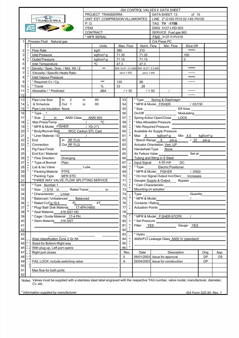
TV -175B
3127-I-HD-003Fuel gas MG
Natural gas
380 31071.35 71.35 100
71.15 71.15 0C 47.3 47.3
120 98.33 28
< 50 < 50
MW 18.57 / Z 0.865MW 18.57 / Z 0.865
2 in 80 Spring & Diaphragm1 80 FISHER 657/30
None*
1 in ANSI 600 LOCKC
FISHER YD (1")WCC Carbon STL Cast
9 kgf/cm # -g 4.5RF FLG 6 psi-g 22RF FLG Vert. UP
None
Diverging Tubing and fitting in S SteelPlain 4-20 mA DC
Electric Positioner PTFE FISHER 3582I
*THREE WAY VALVE, FLOW SPLITTING SERVICEMFR STD IncreasesSupply & OutputNumber 11 5/16 in in Mounting on actuator
Linear Balanced
19.417-4PH H900
416 SST HD17-4 PH FISHER 67CFR
316 SST
Max flow for both ports
YES YES
Area classification Zone 2 Gr IIASized for Bottom-Right way
ANSI IV (standard)
With plug up, Left port opens
cp/cv 1.505
Right port closes
FAIL LOCK: include switching valve
cp/cv 1.505
Valves must be supplied with a stainless steel label engraved with the respective TAG number, valve model, manufacturer, diameter,Cv, etc.
kgf/cm # -gkg/h
Norm. Flow Min. Flow
* MFR & ModelMax Press/Temp
Lube
Units
DATA SHEETLINETAGDWGSERVICE
of
* MFR SERIAL
P. O.ITEMCONTRACT
PROJECTUNIT
9101112
1
23
45678
131415
Flow RateInlet Pressure
Outlet PressureInlet TemperatureDensity / Spec. Grav. / Mol. Wt / Z
Process Fluid Crit Press PC
Viscosity / Specific Heats Ratio
16
17
20
1819
212223242526272829
303132
Pipe Line Size
Pipe Line Insulation & Schedule
INE
L
* Type
* Size ANSI Class
//
* Body/Bonnet Matl* Liner Material / ID /
3334353637383940
InOut
InOutConnection
End
End Ext / MaterialFlg Face Finish
* Flow Direction* Type of BonnetLub & Iso Valve
C
VRE
E
I
S
OND
C
I
ONS
I
T
A0Rev. Date Description
525150494847464544434241
* Size
* Packing Material
* Packing Type
* TypeRated Travel
* Characteristic* Balanced / Unbalanced
* Seat Material* Cage / Guide Material* Stem Material
Cv/Cg
M
RT
I
* Rated FL XT
YDOB
/
BO
T
NN
E
I
SL
A
/
CEP
A
ROS
I
CC
ES
ES
S
676869
7071727374757677787980
Orig.
838281
868584
09/01/200329/04/2003
Issue for approvalIssue for construction
DPDP
App.
* Information supplied by manufacturer ISA Form S20.50, Rev. 1
E
V
VL
A
Input Signal
Quantity
/
On/Off
Spring Action Open/Close* Max Allowable Pressure* Min Required Pressure
Available Air Supply Pressure
* Size
Max Min* Bench Range
Actuator OrientationHandwheel Type
Air Failure Valve Set at
* Type* MFR & Model
OSI
P
Gauges
Eff AreaModulating
Bypass* Cam Characteristic
* On Incr Signal Output Incr/Decr
* Type* MFR & Model /
Type
Contacts / Rating Actuation Points
IONER
T
Filter Gauge
* MFR & Model /
/
TES
RI
A
TCH
SWI
S
TEST
* MFR & Model* Set Pressure
* Hydro ANSI/FCI Leakage Class
ISA CONTROL VALVES II DATA SHEET
Max. Flow
kgf/cm # -gpsi-g
53545556
57585960616263646566
TC
A
ROT
AU
Shut-Off
Inlet Vapour Pressure* Required Cv / Cg* Travel
Allowable / * Predicted dBA%
in
kgf/cm # -g
/ / /
* Plug/ Ball/ Disk Material
/
Notes:
OS
P&ID 3127-F-PI-019
2"-G100-7010.02-145-YN100

8/10/2019 3127-I-HD-003-A.pdf
http://slidepdf.com/reader/full/3127-i-hd-003-apdf 14/15
1514TRANSIERRAEST. COMPRESION VILLAMONTES
PV -181A
3127-I-HD-003Gas to FT-0204 A/B
Gas Natural
380 310 15599.85 95.35 95.35 110
72 72 72 0C 51 51 51
12. 10.7 0.1861 57 32
54.3 < 51.3 < 50
1.4 Kg/m3-MW 18.61.4 Kg/m3-MW 18.6 1.4 Kg/m3-MW 18.6
2 in 80 Spring & Diaphragm2 80 FISHER 357/40
NoneSingle Seat Globe Modulating
2 in ANSI 900 CloseC
FISHER 357 (2")WCC Carbon STL Cast
9 kgf/cm # -g 4.5RTJRTJ
None
Up Tubing and fitting in S Steel4-20 mA DCI/P converter
PTFE FISHER 646
MFR STD IncreasesSupply & OutputMFR STD1/4 in in Mounting on valve
M-Form (= %)Unbalanced
47.5416 SST HD
17-4PH H107517-4 PH H1075 FISHER 67CFR
316 SSTYES YES
Area classification Zone 2 Gr IIA ANSI IV (standard)
0.015 cp / 1.59 0.015 cp / 1.590.015 cp / 1.59
Valves must be supplied with a stainless steel label engraved with the respective TAG number, valve model, manufacturer, diameter,Cv, etc.
kgf/cm # -gkg/h
Norm. Flow Min. Flow
* MFR & ModelMax Press/Temp
Lube
Units
DATA SHEETLINETAGDWGSERVICE
of
* MFR SERIAL
P. O.ITEMCONTRACT
PROJECTUNIT
9101112
1
23
45678
131415
Flow RateInlet Pressure
Outlet PressureInlet TemperatureDensity / Spec. Grav. / Mol. Wt / Z
Process Fluid Crit Press PC
Viscosity / Specific Heats Ratio
16
17
20
1819
212223242526272829
303132
Pipe Line Size
Pipe Line Insulation & Schedule
INE
L
* Type
* Size ANSI Class
//
* Body/Bonnet Matl* Liner Material / ID /
3334353637383940
InOut
InOutConnection
End
End Ext / MaterialFlg Face Finish
* Flow Direction* Type of BonnetLub & Iso Valve
C
VRE
E
I
S
OND
C
I
ONS
I
T
A0Rev. Date Description
525150494847464544434241
* Size
* Packing Material
* Packing Type
* TypeRated Travel
* Characteristic* Balanced / Unbalanced
* Seat Material* Cage / Guide Material* Stem Material
Cv/Cg
M
RT
I
* Rated FL XT
YDOB
/
BO
T
NN
E
I
SL
A
/
CEP
A
ROS
I
CC
ES
ES
S
676869
7071727374757677787980
Orig.
838281
868584
14/01/200329/04/2003
Issue for approvalIssue for construction
DPDP
App.
* Information supplied by manufacturer ISA Form S20.50, Rev. 1
E
V
VL
A
Input Signal
Quantity
/
On/Off
Spring Action Open/Close* Max Allowable Pressure* Min Required Pressure
Available Air Supply Pressure
* Size
Max Min* Bench Range
Actuator OrientationHandwheel Type
Air Failure Valve Set at
* Type* MFR & Model
OSI
P
Gauges
Eff AreaModulating
Bypass* Cam Characteristic
* On Incr Signal Output Incr/Decr
* Type* MFR & Model /
Type
Contacts / Rating Actuation Points
IONER
T
Filter Gauge
* MFR & Model /
/
TES
RI
A
TCH
SWI
S
TEST
* MFR & Model* Set Pressure
* Hydro ANSI/FCI Leakage Class
ISA CONTROL VALVES II DATA SHEET
Max. Flow
kgf/cm # -g
53545556
57585960616263646566
TC
A
ROT
AU
Shut-Off
Inlet Vapour Pressure* Required Cv / Cg* Travel
Allowable / * Predicted dBA%
in
kgf/cm # -g
/ / /
* Plug/ Ball/ Disk Material
/
Notes:
P&ID 3127-F-PI-019
2"-G100-7010.02-009-YN110

8/10/2019 3127-I-HD-003-A.pdf
http://slidepdf.com/reader/full/3127-i-hd-003-apdf 15/15
1515TRANSIERRAEST. COMPRESION VILLAMONTES
PV -181B
3127-I-HD-003Gas to FT-0204 A/B
Gas Natural
380 310 15599.85 95.35 95.35 110
72 72 72 0C 51 51 51
12. 10.7 5.361 57 40
54.3 57 < 50
1.4 Kg/m3-MW 18.61.4 Kg/m3-MW 18.6 1.4 Kg/m3-MW 18.6
2 in 80 Spring & Diaphragm2 80 FISHER 357/40
NoneSingle Seat Globe Modulating
2 in ANSI 900 CloseC
FISHER 357 (2")WCC Carbon STL Cast
9 kgf/cm # -g 4.5RTJRTJ
None
Up Tubing and fitting in S Steel4-20 mA DCI/P converter
PTFE FISHER 646
MFR STD IncreasesSupply & OutputMFR STD1/4 in in Mounting on valve
M-FORM(=%)Unbalanced
47.5416 SST HD
17-4 H107514-4PH H1075 FISHER 67 CFR
316 SSTYES YES
Area classification Zone 2 Gr IIA ANSI IV (standard)
0.015 cp / 1.59 0.015 cp / 1.590.015 cp / 1.59
Valves must be supplied with a stainless steel label engraved with the respective TAG number, valve model, manufacturer, diameter,Cv, etc.
kgf/cm # -gkg/h
Norm. Flow Min. Flow
* MFR & ModelMax Press/Temp
Lube
Units
DATA SHEETLINETAGDWGSERVICE
of
* MFR SERIAL
P. O.ITEMCONTRACT
PROJECTUNIT
9101112
1
23
45678
131415
Flow RateInlet Pressure
Outlet PressureInlet TemperatureDensity / Spec. Grav. / Mol. Wt / Z
Process Fluid Crit Press PC
Viscosity / Specific Heats Ratio
16
17
20
1819
212223242526272829
303132
Pipe Line Size
Pipe Line Insulation & Schedule
INE
L
* Type
* Size ANSI Class
//
* Body/Bonnet Matl* Liner Material / ID /
3334353637383940
InOut
InOutConnection
End
End Ext / MaterialFlg Face Finish
* Flow Direction* Type of BonnetLub & Iso Valve
C
VRE
E
I
S
OND
C
I
ONS
I
T
ARev. Date Description
525150494847464544434241
* Size
* Packing Material
* Packing Type
* TypeRated Travel
* Characteristic* Balanced / Unbalanced
* Seat Material* Cage / Guide Material* Stem Material
Cv/Cg
M
RT
I
* Rated FL XT
YDOB
/
BO
T
NN
E
I
SL
A
/
CEP
A
ROS
I
CC
ES
ES
S
676869
7071727374757677787980
Orig.
838281
868584
29/04/2003 Issue for construction DP App.
* Information supplied by manufacturer ISA Form S20.50, Rev. 1
E
V
VL
A
Input Signal
Quantity
/
On/Off
Spring Action Open/Close* Max Allowable Pressure* Min Required Pressure
Available Air Supply Pressure
* Size
Max Min* Bench Range
Actuator OrientationHandwheel Type
Air Failure Valve Set at
* Type* MFR & Model
OSI
P
Gauges
Eff AreaModulating
Bypass* Cam Characteristic
* On Incr Signal Output Incr/Decr
* Type* MFR & Model /
Type
Contacts / Rating Actuation Points
IONER
T
Filter Gauge
* MFR & Model /
/
TES
RI
A
TCH
SWI
S
TEST
* MFR & Model* Set Pressure
* Hydro ANSI/FCI Leakage Class
ISA CONTROL VALVES II DATA SHEET
Max. Flow
kgf/cm # -g
53545556
57585960616263646566
TC
A
ROT
AU
Shut-Off
Inlet Vapour Pressure* Required Cv / Cg* Travel
Allowable / * Predicted dBA%
in
kgf/cm # -g
/ / /
* Plug/ Ball/ Disk Material
/
Notes:
P&ID 3127-F-PI-019
2"-G100-7010.02-XXX-YN110