3101799-en r1.0 est3x user · pdf fileest3x user guide i content important information iii...
TRANSCRIPT

EST3X User Guide
P/N 3101799-EN • REV 1.0 • ISS 10MAY11

Copyright © 2011 UTC Fire & Security. All rights reserved.
Trademarks and patents
The EST3X name and EST logo are trademarks of UTC Fire & Security.
Other trade names used in this document may be trademarks or registered trademarks of the manufacturers or vendors of the respective products.
Manufacturer Edwards, A Division of UTC Fire & Security Americas Corporation, Inc. 8985 Town Center Parkway, Bradenton, FL 34202, USA
Version This document applies to EST3X control panels with firmware version 1.0.
FCC compliance This equipment has been tested and found to comply with the limits for a Class A digital device, pursuant to part 15 of the FCC Rules. These limits are designed to provide reasonable protection against harmful interference when the equipment is operated in a commercial environment. This equipment generates, uses, and can radiate radio frequency energy and, if not installed and used in accordance with the instruction manual, may cause harmful interference to radio communications. Operation of this equipment in a residential area is likely to cause harmful interference in which case the user will be required to correct the interference at his own expense.
Contact information For contact information, see www.utcfireandsecurity.com.
EST3X User Guide i
Content
Important information iii Fire alarm system limitations vi Intended audience vii
Chapter 1 Introduction 1 System overview 2 System hardware capabilities 2 Overview of operator controls and indicators 4 System operation 8 Event messages 9 User access levels 10 Using the rotary controller 11 Using the paging microphone 13
Chapter 2 Basic operating instructions 15 Checking for active points 16 Finding detectors that may need servicing 17 Viewing history reports 18 Finding firmware and database version numbers 18 Viewing the alarm count 19 Determining panel TCP/IP settings 19 Determining if your 3-MODCOM is NFPA 72 compliant 20 Silencing the panel buzzer 20 Silencing alarm signals 21 Acknowledging events 22 Resetting the fire alarm system 22 Performing a lamp test 22 Activating alarm signals manually 23 Changing the LCD screen language 23
Chapter 3 Advanced operating instructions 25 Changing detector alarm sensitivity 26 Changing event message routes 26 Disabling and enabling devices 27 Disabling and enabling zone groups 28 Setting the system time and date 29 Using a TCP/IP connection to write to the panel 29 Using a TCP/IP connection to read from the panel 30 Guard patrol routes 32

ii EST3X User Guide
Bypassing the photo element on SIGA2-PHS smoke detectors 33
Testing a carbon monoxide (CO) detector 34
Chapter 4 Preventive maintenance and testing 37 Introduction 38 Service provider information 38 Visual inspection schedule 38 Troubleshooting 41
Appendix A System addressing 43 Address formats 44 Card address 44 Hardware layer device addresses 46 Operator layer device address 47 Remote annunciator device addresses 49
Glossary 57
Index 59

EST3X User Guide iii
Important information
Limitation of liability To the maximum extent permitted by applicable law, in no event will UTCFS be liable for any lost profits or business opportunities, loss of use, business interruption, loss of data, or any other indirect, special, incidental, or consequential damages under any theory of liability, whether based in contract, tort, negligence, product liability, or otherwise. Because some jurisdictions do not allow the exclusion or limitation of liability for consequential or incidental damages the preceding limitation may not apply to you. In any event the total liability of UTCFS shall not exceed the purchase price of the product. The forgoing limitation will apply to the maximum extent permitted by applicable law, regardless of whether UTCFS has been advised of the possibility of such damages and regardless of whether any remedy fails of its essential purpose.
Installation in accordance with this manual, applicable codes, and the instructions of the authority having jurisdiction is mandatory.
While every precaution has been taken during the preparation of this manual to ensure the accuracy of its contents, UTCFS assumes no responsibility for errors or omissions.
EST3X FCC compliance This equipment can generate and radiate radio frequency energy. If the equipment is not installed in accordance with this manual, it may cause interference to radio communications. This equipment has been tested and found to comply with the limits for Class A computing devices pursuant to Subpart B of Part 15 of the FCC Rules. These rules are designed to provide reasonable protection against such interference when this equipment is operated in a commercial environment. Operation of this equipment is likely to cause interference, in which case the user, at his own expense, will be required to take whatever measures may be required to correct the interference.
3-MODCOM FCC compliance
Cautions
• To ensure proper operation, this dialer must be installed according to the enclosed installation instructions. To verify that the dialer is operating properly and can successfully report an alarm, it must be tested immediately after
iv EST3X User Guide
installation, and periodically thereafter, according to the enclosed test instructions.
• In order for the dialer to be able to seize the phone line to report an alarm or other event when other customer equipment (telephone, answering system, computer modem, etc.) connected to the same line is in use, the dialer must be connected to a properly installed RJ-31X jack. The RJ-31X jack must be connected in series with, and ahead of, all other equipment attached to the same phone line. Series installation of an RJ-31X jack is depicted in the wiring diagram. If you have any questions concerning these instructions, you should consult your telephone company or a qualified installer.
Testing
When programming emergency numbers or making test calls to emergency numbers, remain on the line and briefly explain to the dispatcher the reason for the call. Perform programming and testing activities in the off-peak hours, such as early morning or late evenings.
Compliance
• For equipment approved before July 23, 2001: This dialer complies with Part 68 of the FCC rules. A label attached to the dialer contains, among other information, the FCC registration number and ringer equivalence number (REN) for this equipment. If requested, this information must be provided to the telephone company.
For equipment approved after July 23, 2001: This dialer complies with Part 68 of the FCC rules and the requirements adopted by the Administrative Council for Terminal Attachments (ACTA). A label attached to the dialer contains, among other information, a product identifier in the format US:AAAEQ##TXXXX. If requested, this information must be provided to the telephone company.
• The plug and jack used to connect the dialer to the premises wiring and telephone network must comply with the applicable FCC Part 68 rules and requirements adopted by ACTA. The dialer must be connected to a compliant RJ-31X or RJ-38X jack using a compliant cord. If a modular telephone cord is supplied with the dialer, it is designed to meet these requirements. See installation instructions for details.
• A ringer equivalence number (REN) is used to determine how many devices you can connect to a telephone line. If the total REN value for all devices connected on a telephone line exceeds that allowed by the telephone company, the devices may not ring on an incoming call. In most (but not all) areas the total REN value should not exceed 5.0. To be certain of the total REN value allowed on a telephone line, contact the local telephone company.

EST3X User Guide v
For products approved after July 23, 2001, the REN is part of the product identifier in the format US:AAAEQ##TXXXX. The digits ## represent the REN without a decimal point. Example: 03 is an REN of 0.3. For earlier products the REN is listed separately.
• If the dialer is harming the telephone network, the telephone company will notify you in advance that temporary discontinuance of service may be required. If advance notice isn’t practical, the telephone company will notify you as soon as possible. You will also be advised of your right to file a complaint with the FCC, if you believe it is necessary.
• The telephone company may make changes to its facilities, equipment, operations, or procedures that could affect the operation of the dialer. If this happens, the telephone company will provide advance notice in order for you to make necessary modifications to maintain uninterrupted service.
• If you are experiencing problems with the dialer, contact the manufacturer for repair or warranty information. If the dialer is harming the telephone network, the telephone company may request that you disconnect the dialer until the problem is resolved.
• The dialer contains no user serviceable parts. In case of defects, return the dialer for repair.
• You may not connect the dialer to a public coin phone or a party line service provided by the telephone company.
3-MODCOM Industry Canada information Note: The Industry Canada label identifies certified equipment. This certification means that the equipment meets certain telecommunications network protective, operational, and safety requirements. Industry Canada does not guarantee the equipment will operate to the user’s satisfaction.
Before installing this equipment, users should ensure that it is permissible to be connected to the facilities of the local telecommunications company. The equipment must also be installed using an acceptable method of connection. The customer should be aware that compliance with the above conditions may not prevent degradation of service in some situations.
Repairs to certified equipment should be made by an authorized Canadian maintenance facility designated by the supplier. Any repairs or alterations made by the user to this equipment, or equipment malfunctions, may give the telecommunications company cause to request the user disconnect the equipment.
vi EST3X User Guide
Caution: Users should not attempt to make connections themselves, but should contact the appropriate electric inspection authority, or electrician, as appropriate.
Users should ensure for their own protection that the electrical ground connections of the power utility, telephone lines, and internal metallic water pipe system, if present, are connected together. This precaution may be particularly important in rural areas.
Note: The Load Number (LN) assigned to each terminal device denotes the percentage of the total load to be connected to a telephone loop which is used by the device, to prevent overloading. The termination on a loop may consist of any combination of devices subject only to the requirements that the sum of the Load Numbers of all the devices does not exceed 100.
Advisory messages Advisory messages alert you to conditions or practices that can cause unwanted results. The advisory messages used in this document are shown and described below.
WARNING: Warning messages advise you of hazards that could result in injury or loss of life. They tell you which actions to take or to avoid in order to prevent the injury or loss of life.
Caution: Caution messages advise you of possible equipment damage. They tell you which actions to take or to avoid in order to prevent the damage.
Note: Note messages advise you of the possible loss of time or effort. They describe how to avoid the loss. Notes are also used to point out important information that you should read.
Fire alarm system limitations
The purpose of an automatic fire alarm system is to provide early detection and warning of a developing fire. There are a number of uncontrollable factors that can prevent or severely limit the ability of an automatic fire alarm system to provide adequate protection. As such, an automatic fire alarm system cannot guarantee against loss of life or loss of property.
EST3X User Guide vii
Two main causes of system failures are improper installation and poor maintenance. The best way to minimize these types of system failures is to have only trained fire alarm system professionals design, install, test, and maintain your fire alarm system in accordance with national and local fire codes.
Fire alarm systems will not operate without electrical power. As fires frequently cause power interruption, we suggest that you discuss ways to safeguard the electrical system with your local fire protection specialist.
In the event your EST3X control panel needs servicing, please contact your system service provider as soon as possible. Refer to “Service provider information” on page 38 for their name and contact information.
Intended audience
The intent of this document is to provide the EST3X life safety system owner with control panel operating instructions. You may assume that your site-specific software has been installed and that the final overall system testing has been completed prior to you using this guide. The extent of your use with panel buttons, indicators, and menus is dependant upon your access privileges.

viii EST3X User Guide
EST3X User Guide 1
Chapter 1 Introduction
Summary
This chapter provides information about your EST3X control panel to give you a basic understanding of its operation.
Content
System overview 2 System hardware capabilities 2 Overview of operator controls and indicators 4 System operation 8 Event messages 9 User access levels 9 Using the rotary controller 11 Using the paging microphone 13

Chapter 1: Introduction
2 EST3X User Guide
System overview
The EST3X control panel can operate as a stand-alone panel, as part of a 64-node EST3X life safety network, or as part of a 64-node EST3 life safety network. The EST3X control panel is listed for the following types of service:
• Commercial protected premises fire alarm control unit
• Smoke control system
• Releasing device control unit
• Emergency communication and relocation
The EST3X control panel is also listed for use as a burglary annunciator when connected to an EST3 life safety system that includes security features.
The EST3X user interface includes indicators and operator controls that allow you to respond quickly in emergency situations. The EST3X user interface gives you the ability to view message details and system reports, and to enable and disable devices and groups. With the correct access level passwords, you can activate and restore sensitivity settings and message routing, test system devices, and other tasks.
System hardware capabilities
The EST3X control panel, in its basic configuration, supports up to:
• 250 addressable devices
• Four Class B notification appliance or auxiliary power output circuits
• 30 remote or graphic annunciators for a total of 30 sets of common controls, 3,840 LED indicators, and 1,920 switches
• Two RS-232 ports (one RJ-11 modular jack for panel programming and diagnostics and one terminal block connection for connecting accessory devices)
With the proper hardware options, you can expand the EST3X control panel to support:
• 1,250 additional addressable devices (1,500 total)
• 24 Class B initiating device circuits
• 12 additional Class B notification appliance circuits (16 total)
• Four Class A notification appliance or auxiliary power output circuits

Chapter 1: Introduction
EST3X User Guide 3
• Three reverse polarity outputs
• Three control-display modules for a total of 72 local LED indicators and 36 local switches
• Two dialer outputs
• One Ethernet connection for panel programming and diagnostics
• Live voice and prerecorded audio messaging
• Connection to an EST3X or EST3 life safety network using copper, fiber optics, or both (maximum network size may not exceed 64 nodes)

Chapter 1: Introduction
4 EST3X User Guide
Overview of controls and indicators
Figure 1: 4X-LCD User Interface
1. Alarm LED
2. Disable LED
3. SUP (Supervisory) LED
4. GND Fault LED
5. CPU Fail LED
6. Trouble LED
7. Power LED
8. Panel Silence button and LED
9. Reset button and LED
10. Acknowledge button and LED
11. Alarm Silence button and LED
12. Rotary controller
13. Display
14. Normal display screen (see Figure 2)
15. Off -normal display screen (see Figure 3)
Chapter 1: Introduction
EST3X User Guide 5
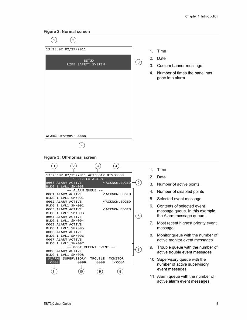
Figure 2: Normal screen
1. Time
2. Date
3. Custom banner message
4. Number of times the panel has gone into alarm
Figure 3: Off-normal screen
1. Time
2. Date
3. Number of active points
4. Number of disabled points
5. Selected event message
6. Contents of selected event message queue. In this example, the Alarm message queue.
7. Most recent highest priority event message
8. Monitor queue with the number of active monitor event messages
9. Trouble queue with the number of active trouble event messages
10. Supervisory queue with the number of active supervisory event messages
11. Alarm queue with the number of active alarm event messages
Chapter 1: Introduction
6 EST3X User Guide
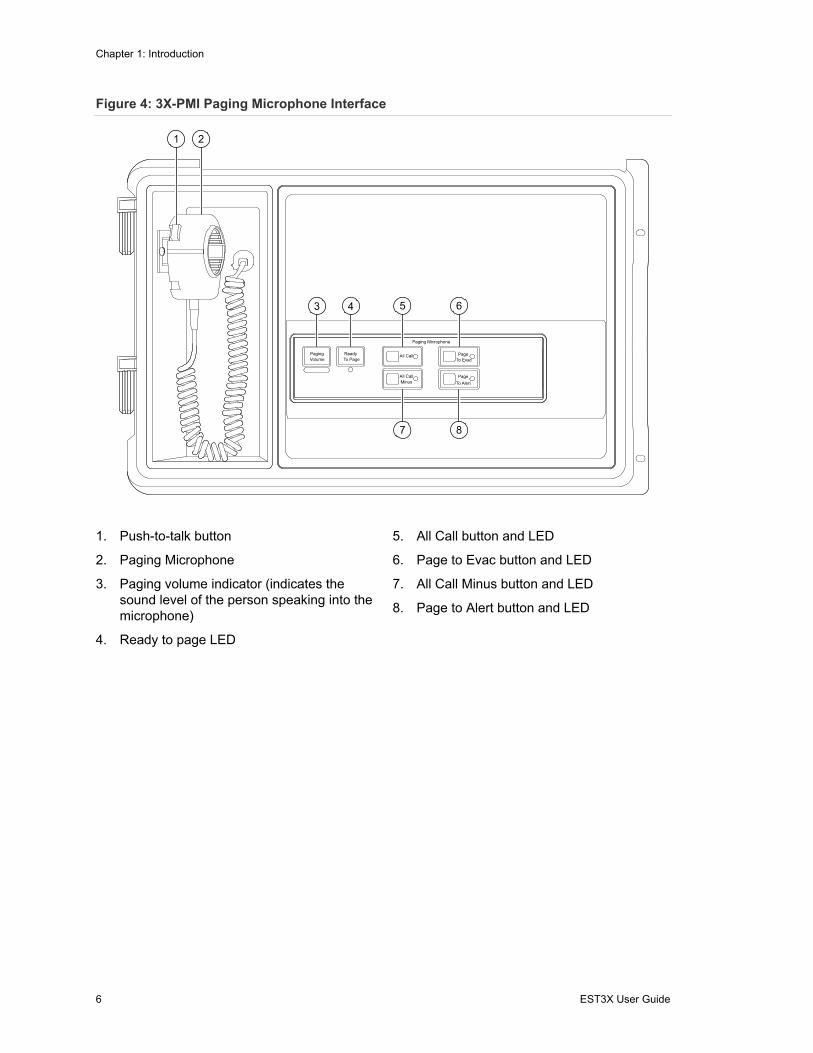
Figure 4: 3X-PMI Paging Microphone Interface
1. Push-to-talk button
2. Paging Microphone
3. Paging volume indicator (indicates the sound level of the person speaking into the microphone)
4. Ready to page LED
5. All Call button and LED
6. Page to Evac button and LED
7. All Call Minus button and LED
8. Page to Alert button and LED

Chapter 1: Introduction
EST3X User Guide 7
Figure 5: RLCD-C and RLCD Remote Annunciator
Controls Enabled
Ack/Silence
Reset
Signal Silence
Drill
Lamp Test
PowerFire AlarmSupervisoryGround FaultTrouble
1
2
3 4 5 6 7 8 9
10
15 14 13 12 11RLCD-C
Controls Enabled
Ack/Silence
Lamp Test
PowerFire AlarmSupervisoryGround FaultTrouble
1
2
3 4 5 9
10
15 14 13 12 11RLCD
1. Display
2. Up button
3. Down button
4. Enter button
5. Lamp Test button and LED
6. Drill button and LED
7. Signal Silence button and LED
8. Reset button and LED
9. Ack/Silence button and LED
10. Controls Enabled LED
11. Trouble LED
12. Ground Fault LED
13. Supervisory LED
14. Fire Alarm LED
15. Power LED

Chapter 1: Introduction
8 EST3X User Guide
Figure 6: RLED-C Remote Annunciator
Controls Enabled
Ack/Silence
Reset
Signal Silence
Drill
Lamp Test
PowerFire AlarmSupervisoryGround FaultTrouble
1 2 3 4
11 10 9 8 7
6
5
12
1. Power LED
2. Fire Alarm LED
3. Supervisory LED
4. Ground Fault LED
5. Trouble LED
6. Controls Enabled LED
7. Ack/Silence button and LED
8. Reset button and LED
9. Signal Silence button and LED
10. Drill button and LED
11. Lamp Test button and LED
12. Programmable LEDs
System operation
The basic function of the EST3X control panel is to monitor status changes in the life safety system and to activate outputs according to the site-specific software. Status change signals, also called events, are classified as follows:
• Alarm (highest priority): Events that signal fire alarms or other life-threatening emergencies
• Supervisory: Events that signal off-normal conditions with sprinkler and extinguishing systems and other equipment related to property safety
• Trouble: Events that signal faults within the system
• Monitor (lowest priority): Events that signal the operation of ancillary equipment

Chapter 1: Introduction
EST3X User Guide 9
During normal operation (no events), the EST3X control panel displays the Normal screen (see Figure 2). When the automatic fire detection system signals a status change, the EST3X control panel:
• Posts the event message for the point that activated the event into the appropriate event message queue and displays the off-normal screen (see Figure 3)
• Turns on the corresponding system status LED
• Turns on the panel buzzer to the pattern for the highest priority active event
• Displays the most recent, highest priority event message (see Figure 3)
• Activates common relays and programmed outputs
Event messages
The EST3X control panel uses event messages to identify points that signal a status change. The first line of the event message displays the event number and the event name. The second line displays the message text. The message text is either the address of the point that activated the event or, if programmed, a location description.
Event messages are stored in queues. There is one queue for each type of event message (see Figure 3).
The EST3X control panel automatically displays the content of the highest priority event message queue, except when you are viewing event messages in another queue. If you are viewing event messages in one queue when a higher priority event message is placed in another queue, the EST3X control panel continues to display the content of the current queue until the user timeout period expires or until you select the other queue.
To view an event message in the current queue:
1. Turn the rotary controller to select the event message. The selected event message appears in the highlighted area at the top of the display.
To view an event message in another queue:
1. Click the rotary controller to display the Queue Menu.
2. Click the event message queue from the list of options.
3. Turn the rotary controller to select the event message.
Chapter 1: Introduction
10 EST3X User Guide
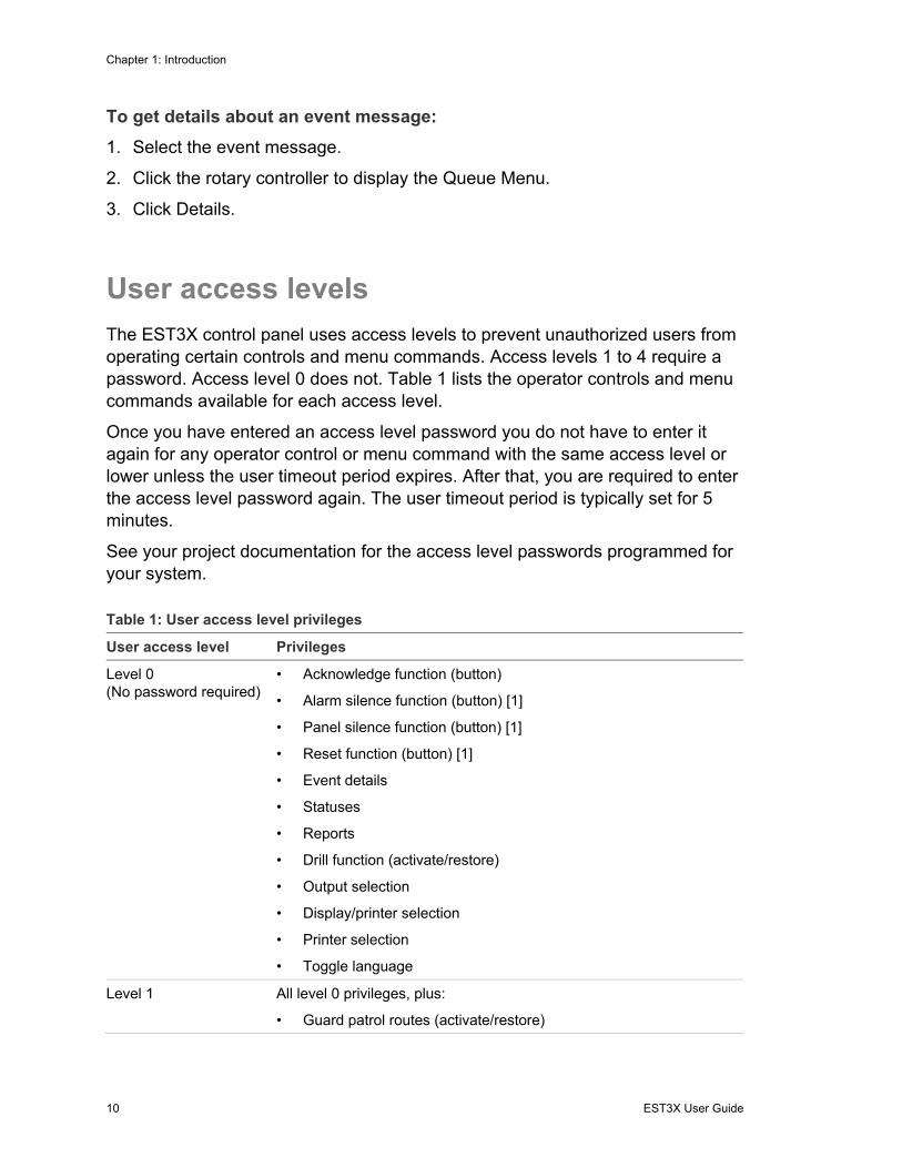
To get details about an event message:
1. Select the event message.
2. Click the rotary controller to display the Queue Menu.
3. Click Details.
User access levels
The EST3X control panel uses access levels to prevent unauthorized users from operating certain controls and menu commands. Access levels 1 to 4 require a password. Access level 0 does not. Table 1 lists the operator controls and menu commands available for each access level.
Once you have entered an access level password you do not have to enter it again for any operator control or menu command with the same access level or lower unless the user timeout period expires. After that, you are required to enter the access level password again. The user timeout period is typically set for 5 minutes.
See your project documentation for the access level passwords programmed for your system.
Table 1: User access level privileges
User access level Privileges
Level 0 (No password required)
• Acknowledge function (button)
• Alarm silence function (button) [1]
• Panel silence function (button) [1]
• Reset function (button) [1]
• Event details
• Statuses
• Reports
• Drill function (activate/restore)
• Output selection
• Display/printer selection
• Printer selection
• Toggle language
Level 1 All level 0 privileges, plus:
• Guard patrol routes (activate/restore)

Chapter 1: Introduction
EST3X User Guide 11
User access level Privileges
Level 2 All level 0 and level 1 privileges, plus:
• Devices (enable/disable)
• Zone groups (enable/disable)
• Remote read lock (activate/restore)
• Remote write unlock (activate/restore)
• Sensor bypass (activate/restore)
• Gas accel response (activate/restore)
• Alternate sensitivity (activate)
• Alternate message route (activate)
• Primary sensitivity (restore)
• Primary message route (restore)
• Change time (program)
• Change date (program)
• Security devices (bypass/remove bypass)
• Security partitions (arm/disarm)
• Change password for level 1 (program)
[1] May be programmed to require an access level password. See your project documentation for details.
Using the rotary controller
The EST3X rotary controller performs the functions of a computer keyboard and the Enter key. Turning the rotary controller allows you to scroll through event messages on the LCD screen, menus and lists, and numbers for panel, card, and device addressing. Pressing (clicking) the rotary controller allows you to access event message details, menus, and selection screens and to enter address numbers and backspaces.
Selecting menus and commands Press the rotary controller to access the first menu, from which you will access other menus. For all menus, turn the dial to scroll to a desired selection. Press the dial to click the selection.
Chapter 1: Introduction
12 EST3X User Guide
Returning to the event message screen or previous screen Pressing the rotary controller while in certain screens returns you to the event message screen or to the previous screen.
Note: Pressing the Acknowledge button also returns you to the event message screen or to the previous screen.
Returning to the previous screen from an address field In an address field, you can return to the previous screen from the first number in the field by turning the rotary controller to the “<” character and then pressing the dial.
For example, in the address field below you are positioned at the first number. If you click the “<” character you will return to the previous screen.
ENTER DEVICE <PCCDDDD
Entering a panel, card, or device address To enter a panel, card, or device address, turn the rotary controller clockwise or counterclockwise to scroll to the desired number (0-9), and then press it to enter the number. Pressing the rotary controller automatically moves the cursor to the next number position.
Note: You do not have to enter a panel number except when you want to enter the panel, card, or device address for a remote EST3X control panel. See your project documentation for a list of panel numbers.
Backspacing In an address field, you can backspace to a previous number by turning the rotary controller to scroll to the “<” character and then pressing the dial. You can then enter the number.
In the address example below, you will be able to change the number 3.
ENTER DEVICE 0103<DDDD

Chapter 1: Introduction
EST3X User Guide 13
Using the paging microphone
The 3X-PMI Paging Microphone Interface (see Figure 4) gives emergency responders the ability to broadcast instructions to occupants throughout the protected premises. There are four types of page you can make:
• All Call: Broadcasts live voice messages throughout the facility
• Page to Evac: Broadcasts live voice messages only to areas receiving evacuation signals
• Page to Alert: Broadcasts live voice messages only to areas receiving alert signals
• All Call Minus: Broadcasts live voice messages only to areas that are not receiving evacuation signals or alert signals
To make an announcement using the paging microphone:
1. Select the area to receive the page by pressing the appropriate page function button. The button’s LED indicates when the system is ready for you to speak.
2. Press the PTT button on the microphone. The Ready to Page LED flashes while the preannouncement tone is sounding.
3. Begin speaking once the Ready to Page LED is on steady. Adjust your voice level so that the Paging Volume indicator only flickers occasionally in the middle. Avoid speaking so loud that the Paging Volume indicator lights all the way to the right.
4. When you are finished speaking, release the PTT button, and then press the page function button again to cancel the page and return the system to its previous condition.
Note: The system automatically cancels the page and returns to its previous condition after a short delay if you do not cancel the page manually.

Chapter 1: Introduction
14 EST3X User Guide

EST3X User Guide 15
Chapter 2 Basic operating instructions
Summary
This chapter provides instructions for operating the basic features of your EST3X life safety system. Basic features are those that anyone can operate. Typically, basic features do not require passwords.
Content
Checking for active points 16 Finding detectors that may need servicing 17 Viewing an event history report 18 Finding firmware and database version numbers 18 Viewing the alarm history 19 Determining the panel TCP/IP settings 19 Determining if your 3-MODCOM is NFPA 72 compliant 20 Silencing the panel buzzer 20 Silencing alarm signals 21 Acknowledging events 22 Resetting the fire alarm system 22 Performing a lamp test 22 Activating alarm signals manually 23 Changing the display screen language 23
Chapter 2: Basic operating instructions
16 EST3X User Guide
Checking for active points
The EST3X control panel provides the following status reports to help you find out if any points in the system are in an active or other off-normal state:
• All Active Points: Lists all points that are in an active or other off-normal state (trouble, disable, etc.)
• Alarm: Lists all alarm points that are in the active state
• Supervisory: Lists all supervisory points that are in the active state
• Trouble: Lists all points that are in the trouble state
• Monitor: Lists all monitor points that are in the active state
• Test: Lists all points in an active service group that are in the active or trouble state
• Disabled Points: Lists all points that are in the disabled state
• Outputs: Lists all output points that are in the active state (audibles, visibles, panel LEDs)
To check for active points:
1. Access the Main menu, and then click Status.
2. Click one of the reports described above.
3. Enter the panel address (PP).
4. Click Display and scroll through the report.
— or —
Click Print Locally.
5. When finished, click the rotary controller or press the Acknowledge button to exit the report.
Chapter 2: Basic operating instructions
EST3X User Guide 17
Finding detectors that may need servicing
The EST3X control panel provides the following maintenance reports to help you find out if any addressable smoke detectors need servicing:
• Dirty Devices > 80%: Lists all addressable smoke detectors that have a %Dirty value of greater than 80%. Smoke detectors that are more than 80% dirty should be cleaned or replaced as soon as possible.
Note: The %Dirty value is an indication of a smoke detector’s ability to compensate for dust and dirt buildup inside the chamber. Smoke detectors with higher %Dirty values are less able to compensate.
• Dirty Devices > 20%: Lists all addressable smoke detectors that have a %Dirty value greater than 20%. A smoke detector that is more than 20% dirty should be noted for possible cleaning or replacing.
• Single Device: Lists the %Dirty value for a single smoke detector. The report also includes the smoke detector’s model type, primary and alternate alarm sensitivity values, and, if programmed, a location description. To view this report you must know the device address of the smoke detector.
• Devices on a Card: Lists the %Dirty value for all of the smoke detectors on a signaling line circuit. The report also includes each smoke detector’s model type, primary and alternate alarm sensitivity values, and, if programmed, a location description. To view this report you must know the panel number, card number, and loop number of the signaling line circuit.
To find detectors that may need servicing:
1. Access the Main Menu, click Reports, and then click Device Maintenance.
2. Click one of the reports described above.
3. Enter the device address (PPCCDDDD), or the loop address (PPCCL).
4. Click Display and scroll through the report.
— or —
Click Print Locally.
5. When finished, click the rotary controller or press the Acknowledge button to exit the report.

Chapter 2: Basic operating instructions
18 EST3X User Guide
Viewing history reports
The EST3X control panel provides the following history reports for determining when the last 1,100 events and operator commands were activated or restored:
• History with Text: Provides a history of events and operator commands logged by the panel. For each point that activated or restored, the detail includes the point’s message text.
• History without Text: Provides a history of events and operator commands logged by the system. For each point that activated or restored, the detail includes the point’s device address.
To view a history report:
1. Access the Main Menu, click Reports, and then click History.
2. Click one of the reports described above.
3. Enter the panel address (PP).
4. Click Display and scroll through the report.
— or —
Click Print Locally.
5. When finished, click the rotary controller or press the Acknowledge button to exit the report.
Finding firmware and database version numbers
By viewing a Revisions report, you can find the version numbers for the following:
• The CPU firmware
• The project database and the SDU used to compile and download the project database
• The audio database, if equipped with a paging microphone
• The application code (firmware), bootloader code, and database for each card installed in the panel
To view the Revisions report:
1. Access the Main Menu, click Reports, and then click Revisions.
2. Enter the panel address (PP).

Chapter 2: Basic operating instructions
EST3X User Guide 19
3. Click Display and scroll through the report.
— or —
Click Print Locally.
4. When finished, click the rotary controller or press the Acknowledge button to exit the report.
Viewing the alarm count
The EST3X control panel records how many times it went into the alarm condition. During normal operation, the alarm count is displayed on the LCD. When the EST3X user interface displays the off-normal screen, you must run a Revisions report to see the alarm count.
To view the alarm count:
1. Access the Main Menu, click Reports, and then click Revisions.
2. Enter the panel address (PP).
3. Click Display and scroll through the report. The alarm count is on the second line of the report.
— or —
Click Print Locally.
4. When finished, click the rotary controller or press the Acknowledge button to exit the report.
Determining panel TCP/IP settings
If your panel is equipped with an Ethernet (TCP/IP) connection, you may be asked to provide the IP address, subnet mask, and gateway settings.
To determine the panel TCP/IP settings:
1. Access the Main Menu, click Reports, and then click Revisions.
2. Enter the panel address (PP).
3. Click Display and scroll through the report. The settings are at the bottom of the report.
— or —
Click Print Locally.

Chapter 2: Basic operating instructions
20 EST3X User Guide
4. When finished, click the rotary controller or press the Acknowledge button to exit the report.
Determining if your 3-MODCOM is NFPA 72 compliant
A MODCOM compliance report tells you if the 3-MODCOM installed in the panel meets NFPA 72 configuration requirements. The report does not indicate why the 3-MODCOM may be noncompliant.
To view the MODCOM Compliance report:
1. Access the Main Menu, click Reports, and then click Modcom Compliance.
2. Enter the panel address (PP).
3. Click Display and scroll through the report.
— or —
Click Print Locally.
4. When finished, click the rotary controller or press the Acknowledge button to exit the report.
Silencing the panel buzzer
The EST3X control panel sounds the panel buzzer when an event message is posted into one of the event message queues. Pressing the Panel Silence button or acknowledging the event message silences the buzzer. The panel buzzer automatically re-sounds when a new event message is posted or when the panel trouble re-sound timer expires (typically after 24 hours).
Notes
• The panel buzzer may be configured to sound periodically to remind you that the panel has been silenced.
• For nonlatching events, the panel buzzer automatically silences when the event is restored.
• Pressing the Panel Silence button also silences the buzzer on remote annunciators, provided that the remote annunciators are communicating.
Chapter 2: Basic operating instructions
EST3X User Guide 21
To silence the panel buzzer:
1. Press the Panel Silence button or acknowledge the event message.
2. If prompted, enter the access level password.
Silencing alarm signals
WARNING: Death or serious injury. The protected premises may be occupied. Do not silence alarm signals or reset the control panel unless you are authorized to do so and only after all occupants have been evacuated.
Pressing the Alarm Silence button silences all audible alarm signals and, if configured, all visible alarm signals. Pressing the Alarm Silence button does not silence alarm signals under the following conditions:
• When a waterflow alarm switch is active and the system is configured to prevent silencing alarm signals activated by a waterflow alarm switch
• When the system is configured to delay the silencing of alarm signals, in which case the Alarm Silence button may be inoperable for up to three minutes following an alarm event
Silenced alarm signals automatically turn back on when:
• The Alarm Silence button is pressed a second time
• Another alarm input activates
• Another alarm input in the same zone activates, unless the system is configured to prevent it
To silence alarm signals:
1. Press the Alarm Silence button.
2. If prompted, enter the access level password.
Acknowledging events
Acknowledging an event confirms that you have seen the event message. When you acknowledge an event, the EST3X control panel places a check mark and the word “Acknowledged” next to the event. On proprietary systems, you cannot silence the panel until all events have been acknowledged.
Chapter 2: Basic operating instructions
22 EST3X User Guide
To acknowledge an event:
1. Press the Acknowledge button.
Resetting the fire alarm system
WARNING: Death or serious injury. The protected premises may be occupied. Do not reset the fire alarm system until the proper authorities have determined that the threat of fire is no longer present.
Pressing the Reset button restores the fire alarm system to its normal state —provided that all latched inputs have been restored. If alarm signal initiating devices have not been restored, active alarm signals remain active and silenced alarm signals remain silenced.
Notes
• System programming may render the Reset button inoperable for up to three minutes following an alarm event.
• Resetting the system does not enable disabled points or restore outputs activated by a switch.
To reset the fire alarm system:
1. Press the Reset button.
2. If prompted, enter the access level password.
Performing a lamp test
Use the Lamp Test command on the Test Menu to verify the operation of the LCD and LED indicators. The lamp test command temporarily turns on the panel buzzer, all LED indicators, and every pixel on the LCD. The lamp test command only operates the indicators on the panel from which the command is initiated.
To perform a lamp test:
1. Access the Main Menu, click Test, and then click Lamp Test.

Chapter 2: Basic operating instructions
EST3X User Guide 23
Activating alarm signals manually
The EST3X drill feature lets you activate alarm signals manually without putting the panel into alarm. When you activate a drill, all audible alarm signals turn on and, if configured, all visible alarm signals turn on, but other automatic fire alarm responses are not activated. The alarm signals remain active until the drill is canceled.
To activate a drill:
1. Access the Main Menu, click Activate, and then click Drill.
2. If prompted, enter the access level password.
To cancel a drill:
1. Press the Alarm Silence button.
— or —
Access the Main Menu, click Restore, and then click Drill.
Changing the LCD screen language
Use the Toggle Language command on the Program Menu to toggle the LCD screen text to a secondary language.
Note: The panel must be configured for a secondary language.
To change the LCD screen language:
1. Access the Main Menu, and then click Program.
2. Click Toggle Language.

Chapter 2: Basic operating instructions
24 EST3X User Guide

EST3X User Guide 25
Chapter 3 Advanced operating instructions
Summary
This chapter provides instructions for operating the advanced features of your EST3X life safety system. Advanced features alter system operation and require the access level 2 password or greater.
Content
Changing detector alarm sensitivity 26 Changing event message routes 26 Disabling and enabling devices 27 Disabling and enabling zone groups 28 Setting the system time and date 29 Using a TCP/IP connection to write to the panel 29 Using a TCP/IP connection to read from the panel 30 Guard patrol routes 32
Activating a guard patrol route 32 Restoring a guard patrol 32
Bypassing the photo element on SIGA2-PHS smoke detectors 33 Testing a carbon monoxide (CO) detector 34

Chapter 3: Advanced operating instructions
26 EST3X User Guide
Changing detector alarm sensitivity
Your fire alarm system can be programmed with two different alarm sensitivity settings. The alarm sensitivity setting determines how easily automatic fire detectors can sense a fire alarm condition. Typically, the primary alarm sensitivity setting is programmed for daytime operation and the alternate alarm sensitivity setting is programmed for nighttime and weekend operation.
To activate the alternate alarm sensitivity settings:
1. Access the Main Menu, and then click Activate.
2. Click Alt Sensitivity.
3. Enter the access level password.
To restore the primary alarm sensitivity settings:
1. Access the Main Menu, and then click Restore.
2. Click Primary Sensitivity.
3. Enter the access level password.
Changing event message routes
Your fire alarm system can be programmed with a primary message route and an alternate message route. The message route setting determines where event messages are displayed. Typically, the primary message route is programmed for daytime operation and the alternate message route is programmed for nighttime and weekend operation.
In most applications, a time control is used to automatically switch event messages over to their alternate route setting. When the time control is restored, event messages are automatically switched back to their primary route settings.
To activate alternate message routing:
1. Access the Main Menu, and then click Activate.
2. Click Alt Message Route.
3. Enter the access level password.

Chapter 3: Advanced operating instructions
EST3X User Guide 27
To restore primary message routing:
1. Access the Main Menu, and then click Restore.
2. Click Primary Msg Route.
3. Enter the access level password.
Disabling and enabling devices
Disabling a device prevents the EST3X control panel from processing status change signals from the device, or changing the output state of the device, until the device is enabled. For example, the EST3X control panel does not generate an alarm active event when you activate a disabled detector, but will do so after the detector is enabled.
The EST3X control panel keeps track of how many times you disable and enable a device. You must enable a device the same number of times you disable it in order to return the device to its initial condition.
Device addresses are listed in Appendix A “System addressing” on page 43.
Notes
• You cannot disable a device configured as a common alarm output.
• Disabling the device address for the dialer or a dialer account deletes all event messages sent to that account before they are transmitted. The dialer still transmits the account’s test-abnormal message and any message that was in the dialer queue before the account was disabled.
• Disabling all of the devices in a zone group automatically disables the zone group. Enabling any device in the zone group automatically enables the zone group.
To disable a device:
1. Access the Main Menu, and then click Disable.
2. Click Device, and then enter the device address (PPCCDDDD).
3. Enter the access level password.
To enable a device:
1. Access the Main Menu, and then click Enable.
2. Click Device, and then enter the device address (PPCCDDDD).
3. Enter the access level password.
Chapter 3: Advanced operating instructions
28 EST3X User Guide
Disabling and enabling zone groups
Disabling a zone group prevents the EST3X control panel from processing status change signals from every device in the zone group until the zone group is enabled. For example, the EST3X control panel does not generate an alarm active event when you activate a detector in a disabled zone group, but will do so after the zone group is enabled.
The EST3X control panel keeps track of how many times you disable and enable a zone group. You must enable a zone group the same number of times you disable it in order to return the zone group to its initial condition.
Notes
• The control panel tracks events from a disabled zone group but does not process them until the zone group is enabled.
• If you disabled the zone group by disabling all of the devices in the zone group, enabling the zone group enables all of the devices in the zone group.
To disable a zone group:
1. Access the Main Menu, and then click Disable.
2. Click Group, and then select Zone Group.
3. Scroll through the list and click the desired zone group.
4. Enter the access level password.
To enable a zone group:
1. Access the Main Menu, and then click Enable.
2. Click Group, and then select Zone Group.
3. Scroll through the list and click the desired zone group.
4. Enter the access level password.
Setting the system time and date
The EST3X control panel incorporates a system clock to time stamp events and to activate time controls. The time is presented in 24-hour format. The date is presented in month-day-year format.
To set the time:
1. Access the Main Menu, click Program, and then click Change Time.

Chapter 3: Advanced operating instructions
EST3X User Guide 29
2. Enter the access level password.
3. Enter the hour, minutes, and seconds (HHMMSS).
Examples: 000000 = midnight 010000 = 1:00 a.m. 120000 = noon 130000 = 1:00 p.m. 235900 = 11:59 p.m.
To set the date:
1. Access the Main Menu click Program, and then click Change Date.
2. Enter the access level password.
3. Enter the date (MMDDYYYY).
Using a TCP/IP connection to write to the panel
If your EST3X control panel is equipped with an Ethernet card, your service provider can use the TCP/IP connection to write (download) the project database to the panel instead of using an RS-232 connection. By default, this feature is “locked” to prevent someone from changing the project database without permission. You cannot write to the panel until it is “unlocked.”
Notes
• Activating and restoring the Remote Write Unlock command does not affect downloading the project database using an RS-232 connection.
• The Remote Write Unlock command times out after 15 minutes.
• This function should only be used by the installer or service provider. Changes to the fire alarm system must be tested and may require local authority approval.
To allow writing to the panel:
1. Access the Main Menu, and then click Activate.
2. Click Remote Write Unlock.
3. Click By Panel, and then enter the panel address (PP).
— or —
Click All Panels.
Chapter 3: Advanced operating instructions
30 EST3X User Guide
4. Enter the access level password.
To prevent writing to the panel:
1. Access the Main Menu, and then click Restore.
2. Click Remote Write Unlock.
3. Click By Panel, and then enter the panel address (PP).
— or —
Click All Panels.
4. Enter the access level password.
Using a TCP/IP connection to read from the panel
If your EST3X control panel is equipped with an Ethernet card, your service provider can use the TCP/IP connection to read status and diagnostic information from the panel instead of using an RS-232 connection. By default, this feature is “unlocked.” Locking this feature prevents you from reading from the panel until it is unlocked.
Notes
• The Remote Read Lock command does not automatically time out.
• Activating and restoring the Remote Read Lock command does not affect reading panel status and diagnostic information using an RS-232 connection.
To prevent reading from the panel:
1. Access the Main Menu, and then click Activate.
2. Click Remote Read Lock.
3. Click By Panel, and then enter the panel address (PP).
— or —
Click All Panels.
4. Enter the access level password.
To allow reading from the panel:
1. Access the Main Menu, and then click Restore.
2. Click Remote Read Lock.

Chapter 3: Advanced operating instructions
EST3X User Guide 31
3. Click By panel, and then enter the panel address (PP).
— or —
Click All Panels.
4. Enter the access level password.
Guard patrol routes
The guard patrol feature allows you to monitor the activities of security guards. Guards are required to walk any one of a number of predetermined routes called tours. During each tour, the guard must activate guard patrol stations that are strategically located along the route. Should a guard activate a station too early, too late, or out of sequence, an active guard patrol event message shows on the LCD screen. When a guard patrol alarm is generated, you must restore the guard patrol route to clear the alarm.
Activating a guard patrol route Activating a guard patrol route starts the system’s early, late, and out of sequence sensing mechanisms. If a station reports in early, late, or out of sequence, the guard patrol sensing mechanisms stop and the tour is ended.
To activate a guard patrol route:
1. Access the Main Menu, and then click Activate.
2. Click Guard Patrol Route, and then click the route to be activated.
3. Enter the access level password.
Note: A guard patrol route is activated automatically when you activate the first guard patrol station on the route.
Restoring a guard patrol When a guard patrol tour ends because a guard patrol station was not activated at the proper time, you must restore the guard patrol group to which the station belonged.

Chapter 3: Advanced operating instructions
32 EST3X User Guide
To restore a guard patrol:
1. Access the Main Menu, and then click Restore.
2. Click Guard Patrol Route, and then click the route to be restored.
3. Enter the access level password.
Bypassing the photo element on SIGA2-PHS smoke detectors
If your fire alarm system is equipped with SIGA2-PHS combination photo-heat detectors, you can temporarily bypass the photo element and use only the heat element to detect a fire.
Notes
• The Sensor Bypass command works only with SIGA2-PHS detectors whose Primary Operation is set for "Photo is Supervisory | Heat is AlarmHeat."
• Bypassing the photo element activates a “Sensor Bypass Active” trouble event.
• If the photo element activates while it is bypassed, a “Disabled Active Event” is recorded in the event history.
To bypass the photo element on a SIGA2-PHS:
1. Access the Main Menu, and then click Activate.
2. Click Sensor Bypass, and then enter the device address (PPCCDDDD).
3. Enter the access level password.
To unbypass the photo element on a SIGA2-PHS:
1. Access the Main Menu, and then click Restore.
2. Click Sensor Bypass, and then enter the device address (PPCCDDDD).
3. Enter the access level password.
Testing a carbon monoxide (CO) detector
SIGA2 carbon monoxide (CO) detectors have an accelerated response mode that you can use when testing. In normal mode, SIGA2 CO detectors activate after carbon monoxide levels reach 400 ppm (parts per million) for 4 minutes. In

Chapter 3: Advanced operating instructions
EST3X User Guide 33
accelerated response mode, SIGA2 CO detectors activate within 4 to 8 seconds after reaching 400 ppm.
Notes
• The SIGA2 CO detector normal response rate mimics the normal absorption rate of CO in the bloodstream.
• If you do not restore the response mode, CO detection returns to its normal response time after 4 hours.
To change the CO rate of detection:
1. Access the Main Menu, and then click Activate.
2. Click Gas Accel Response, and then enter the device address (PPCCDDDD).
3. Enter the access level password.
To restore the CO rate of detection:
1. Access the Main Menu, and then click Restore.
2. Click Gas Accel Response, and then enter the device address (PPCCDDDD).
3. Enter the access level password.

Chapter 3: Advanced operating instructions
34 EST3X User Guide

EST3X User Guide 35
Chapter 4 Preventive maintenance and testing
Summary
This chapter provides instructions for maintaining and testing your EST3X life safety system.
Content
Introduction 38 Service provider information 38 Visual inspection schedule 38
Routine maintenance schedule 40 Troubleshooting 41
Chapter 4: Preventive maintenance and testing
36 EST3X User Guide
Introduction
Periodic visual inspections and maintenance testing must be performed on your EST3X life safety system to ensure that it is operating correctly and as required by the local authority having jurisdiction (AHJ). Maintenance testing is performed by your service provider or a qualified technician with a complete understanding of the system hardware and functions.
Visual inspection and maintenance schedules are provided in this section, as well as a form to document your service provider’s contact information.
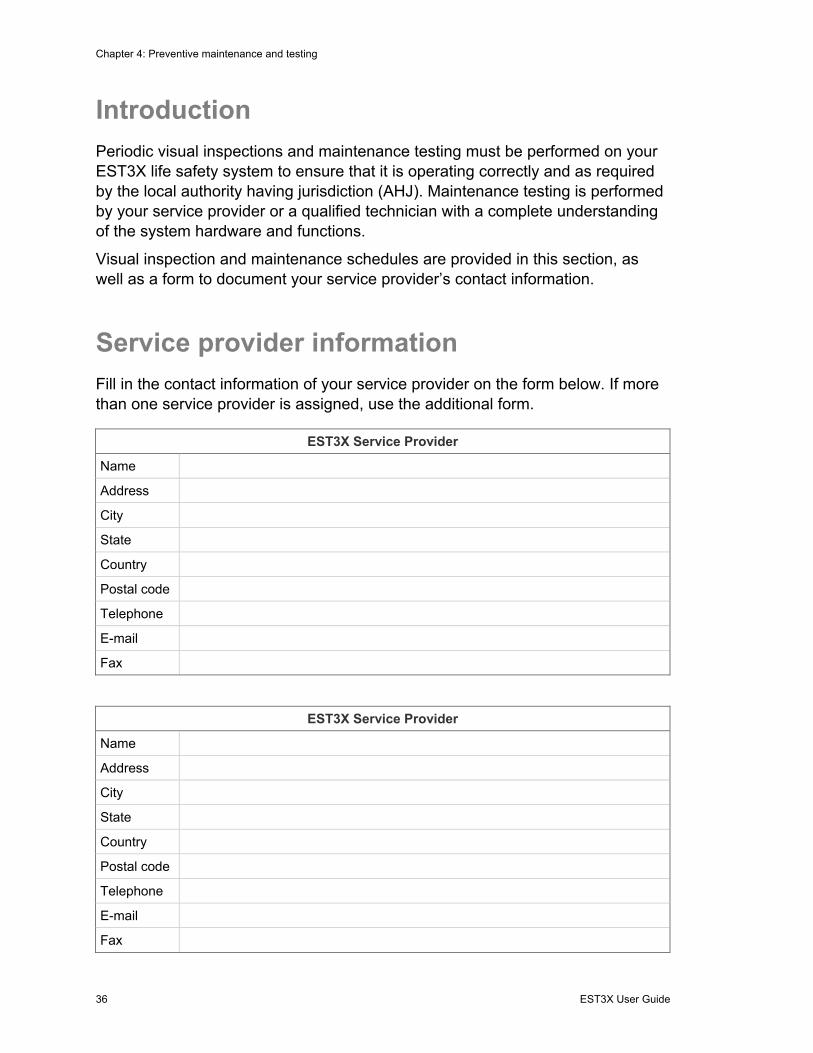
Service provider information
Fill in the contact information of your service provider on the form below. If more than one service provider is assigned, use the additional form.
EST3X Service Provider
Name
Address
City
State
Country
Postal code
Telephone
Fax
EST3X Service Provider
Name
Address
City
State
Country
Postal code
Telephone
Fax
Chapter 4: Preventive maintenance and testing
EST3X User Guide 37
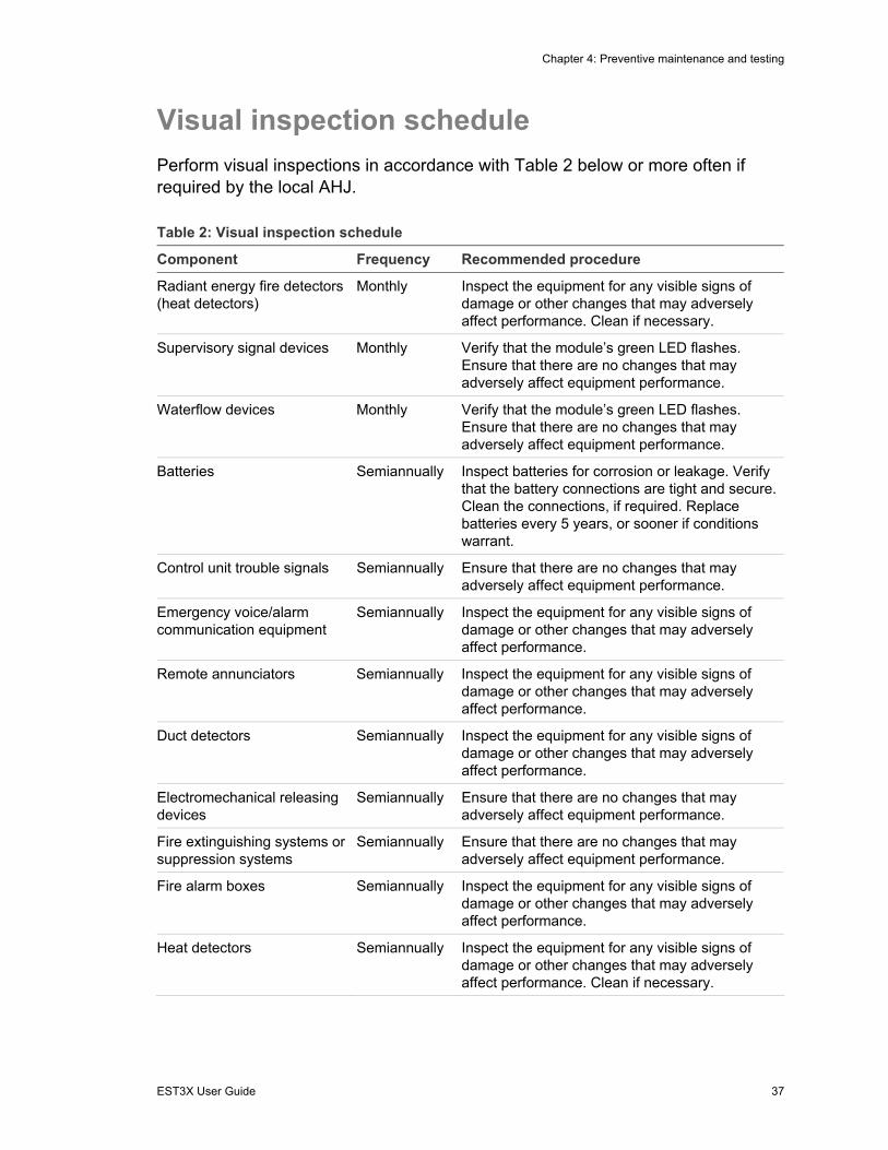
Visual inspection schedule
Perform visual inspections in accordance with Table 2 below or more often if required by the local AHJ.
Table 2: Visual inspection schedule
Component Frequency Recommended procedure
Radiant energy fire detectors (heat detectors)
Monthly Inspect the equipment for any visible signs of damage or other changes that may adversely affect performance. Clean if necessary.
Supervisory signal devices Monthly Verify that the module’s green LED flashes. Ensure that there are no changes that may adversely affect equipment performance.
Waterflow devices Monthly Verify that the module’s green LED flashes. Ensure that there are no changes that may adversely affect equipment performance.
Batteries Semiannually Inspect batteries for corrosion or leakage. Verify that the battery connections are tight and secure. Clean the connections, if required. Replace batteries every 5 years, or sooner if conditions warrant.
Control unit trouble signals Semiannually Ensure that there are no changes that may adversely affect equipment performance.
Emergency voice/alarm communication equipment
Semiannually Inspect the equipment for any visible signs of damage or other changes that may adversely affect performance.
Remote annunciators Semiannually Inspect the equipment for any visible signs of damage or other changes that may adversely affect performance.
Duct detectors Semiannually Inspect the equipment for any visible signs of damage or other changes that may adversely affect performance.
Electromechanical releasing devices
Semiannually Ensure that there are no changes that may adversely affect equipment performance.
Fire extinguishing systems or suppression systems
Semiannually Ensure that there are no changes that may adversely affect equipment performance.
Fire alarm boxes Semiannually Inspect the equipment for any visible signs of damage or other changes that may adversely affect performance.
Heat detectors Semiannually Inspect the equipment for any visible signs of damage or other changes that may adversely affect performance. Clean if necessary.

Chapter 4: Preventive maintenance and testing
38 EST3X User Guide
Component Frequency Recommended procedure
Smoke detectors Semiannually Inspect the equipment for any visible signs of damage or other changes that may adversely affect performance. Clean if necessary.
Guard tour equipment Semiannually Inspect the equipment for any visible signs of damage or other changes that may adversely affect performance.
Interface equipment Semiannually Inspect the equipment for any visible signs of damage or other changes that may adversely affect performance.
Alarm notification appliances Semiannually Verify that the module’s green LED flashes. Ensure that there are no changes that may adversely affect equipment performance.
Supervising station fire alarm system transmitters
Semiannually Ensure that there are no changes that may adversely affect equipment performance.
Control unit Annually Inspect the equipment for any visible signs of damage or other changes that may adversely affect performance.
Fiber optic cable connections Annually Inspect the cables for any visible signs of damage, loose connections, or other changes that may adversely affect performance
Routine maintenance schedule Routine maintenance and testing should be scheduled for your EST3X life safety system in accordance with Table 3 below or more often if required by the local AHJ.
Note: Only your system service provider or a qualified technician with a complete understanding of the system hardware and functions should perform system maintenance and tests.
Table 3: Routine maintenance schedule
Component Frequency
Control equipment [1] Quarterly / Annually
Supervisory signal devices (except valve tamper switches) Quarterly
Off-premises transmission equipment Quarterly
Waterflow devices Semiannually
Valve tamper switches Semiannually
Batteries [2] Annually

Chapter 4: Preventive maintenance and testing
EST3X User Guide 39
Component Frequency
Control unit trouble signals Annually
Fiber optic cable connections Annually
Emergency voice/alarm communication equipment Annually
Remote annunciators Annually
Smoke detectors Annually
Heat detectors Annually
Fire alarm boxes Annually
Fire extinguishing systems or suppression systems Annually
Guard tour equipment Annually
Interface equipment Annually
Audible notification appliances Annually
Textual audible notification appliances (speakers) Annually
Visible notification appliances Annually
Supervising station fire alarm system transmitters Annually
[1] Test control equipment quarterly when it is not connected to a supervising station. [2] Replace batteries every five years, or sooner if conditions warrant.
Troubleshooting
Problems with your EST3X life safety system can generally be classified in two categories: application programming problems and hardware (including firmware) problems. Many times hardware problems are identified by the system itself. Application programming problems are typically suspected when an incorrect response happens, or when a response fails to happen or happens at the wrong time.
Only your system service provider or a qualified technician with a complete understanding of the system hardware and functions should perform system servicing and repairs. Refer to “Service provider information” on page 38 for their contact information. Refer to the EST3X Technical Reference Manual (P/N 3101888-EN) for detailed troubleshooting information.
Before contacting your service provider, make note of the following:
• Messages shown on the LCD screen • Construction in the area that may have caused the problem • Adverse weather that may have caused the problem • Damage to any equipment

Chapter 4: Preventive maintenance and testing
40 EST3X User Guide

EST3X User Guide 41
Appendix A System addressing
Summary
This appendix provides an easy way to look up card and device addresses.
Content
Address formats 44 Card address 44 Hardware layer device addresses 46 Operator layer device address 47 Remote annunciator device addresses 49
Appendix A: System addressing
42 EST3X User Guide
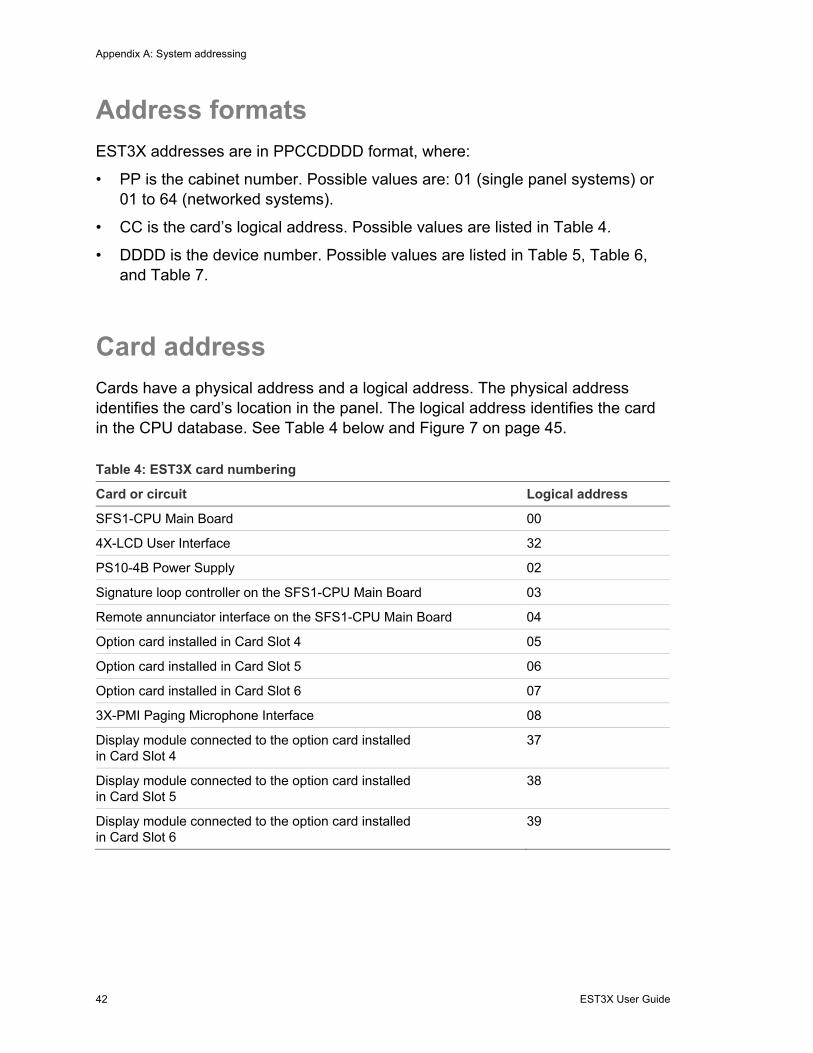
Address formats
EST3X addresses are in PPCCDDDD format, where:
• PP is the cabinet number. Possible values are: 01 (single panel systems) or 01 to 64 (networked systems).
• CC is the card’s logical address. Possible values are listed in Table 4.
• DDDD is the device number. Possible values are listed in Table 5, Table 6, and Table 7.
Card address
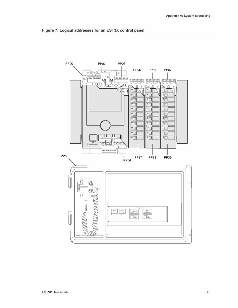
Cards have a physical address and a logical address. The physical address identifies the card’s location in the panel. The logical address identifies the card in the CPU database. See Table 4 below and Figure 7 on page 45.
Table 4: EST3X card numbering
Card or circuit Logical address
SFS1-CPU Main Board 00
4X-LCD User Interface 32
PS10-4B Power Supply 02
Signature loop controller on the SFS1-CPU Main Board 03
Remote annunciator interface on the SFS1-CPU Main Board 04
Option card installed in Card Slot 4 05
Option card installed in Card Slot 5 06
Option card installed in Card Slot 6 07
3X-PMI Paging Microphone Interface 08
Display module connected to the option card installed in Card Slot 4
37
Display module connected to the option card installed in Card Slot 5
38
Display module connected to the option card installed in Card Slot 6
39
Appendix A: System addressing
EST3X User Guide 43
Figure 7: Logical addresses for an EST3X control panel
PP02PP00 PP03
PP05 PP06 PP07
PP04PP08
TB2
TB1
J1
B+
B–
A+
A–
B+
B–
SH
SPMWPR1
N/C
LOOP1 LOOP1 LOOP1
B+
B-
A+
A-
B+
B-
SH
N/C
LOOP2LOOP2LOOP2
SPMWPR
TB2
TB1
J1
B+
B–
A+
A–
B+
B–
SH
SPMWPR1
N/C
LOOP1 LOOP1 LOOP1
B+
B-
A+
A-
B+
B-
SH
N/C
LOOP2LOOP2LOOP2
SPMWPR
TB2
TB1
J1
B+
B–
A+
A–
B+
B–
SH
SPMWPR1
N/C
LOOP1 LOOP1 LOOP1
B+
B-
A+
A-
B+
B-
SH
N/C
LOOP2LOOP2LOOP2
SPMWPR
PP37 PP38 PP39
PagingVolume To Page
Ready All Call
All Call Page
Page
Minus To Alert
To Evac
Paging Microphone
Appendix A: System addressing
44 EST3X User Guide
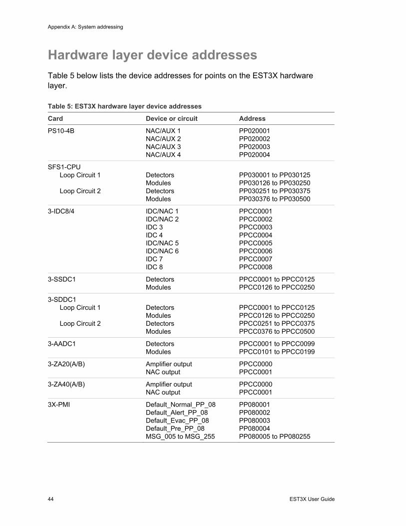
Hardware layer device addresses
Table 5 below lists the device addresses for points on the EST3X hardware layer.
Table 5: EST3X hardware layer device addresses
Card Device or circuit Address
PS10-4B NAC/AUX 1 NAC/AUX 2 NAC/AUX 3 NAC/AUX 4
PP020001 PP020002 PP020003 PP020004
SFS1-CPU Loop Circuit 1 Loop Circuit 2
Detectors Modules Detectors Modules
PP030001 to PP030125 PP030126 to PP030250 PP030251 to PP030375 PP030376 to PP030500
3-IDC8/4 IDC/NAC 1 IDC/NAC 2 IDC 3 IDC 4 IDC/NAC 5 IDC/NAC 6 IDC 7 IDC 8
PPCC0001 PPCC0002 PPCC0003 PPCC0004 PPCC0005 PPCC0006 PPCC0007 PPCC0008
3-SSDC1 Detectors Modules
PPCC0001 to PPCC0125 PPCC0126 to PPCC0250
3-SDDC1 Loop Circuit 1 Loop Circuit 2
Detectors Modules Detectors Modules
PPCC0001 to PPCC0125 PPCC0126 to PPCC0250 PPCC0251 to PPCC0375 PPCC0376 to PPCC0500
3-AADC1 Detectors Modules
PPCC0001 to PPCC0099 PPCC0101 to PPCC0199
3-ZA20(A/B) Amplifier output NAC output
PPCC0000 PPCC0001
3-ZA40(A/B) Amplifier output NAC output
PPCC0000 PPCC0001
3X-PMI Default_Normal_PP_08 Default_Alert_PP_08 Default_Evac_PP_08 Default_Pre_PP_08 MSG_005 to MSG_255
PP080001 PP080002 PP080003 PP080004 PP080005 to PP080255

Appendix A: System addressing
EST3X User Guide 45
Operator layer device address
Table 6 below lists the device addresses for points on the EST3X operator layer. See also Figure 8 on page 48.
Table 6: EST3X operator layer device addresses
Module type LED or switch Address
12SW/12LED SW01 to SW12 LED01 to LED12
PPCC0001 to PPCC0012 PPCC0129 to PPCC0140
12SW/24LED SW01 to SW12 LED01 to LED24
PPCC0001 to PPCC0012 PPCC0129 to PPCC0152
24LED LED01 to LED24 PPCC0129 to PPCC0152
3SW/3LED×6 SW01 to SW18 LEDs
PPCC0001 to PPCC0018 PPCC0129 to PPCC0146
3SW/4LED×4 SW01 to SW12 LED01 LED02 LED03 LED04 LED05 LED06 LED07 LED08 LED09 LED10 LED11 LED12 LED13 LED14 LED15 LED16
PPCC0001 to PPCC0012 PPCC0129 PPCC0131 PPCC0132 PPCC0133 PPCC0135 PPCC0137 PPCC0138 PPCC0139 PPCC0141 PPCC0143 PPCC0144 PPCC0145 PPCC0147 PPCC0149 PPCC0150 PPCC0151

Appendix A: System addressing
46 EST3X User Guide
Figure 8: Operator layer LED and switch numbering
LED01 SW01
SW12
LED01
LED24
SW01
SW12
LED01
LED16
SW01
SW12
12SW/12LED 12SW/24LED 24LED
3SW/3LED×6 3SW/4LED×4
LED12
LED01
LED24
LED01
LED18
SW01
SW18
Appendix A: System addressing
EST3X User Guide 47
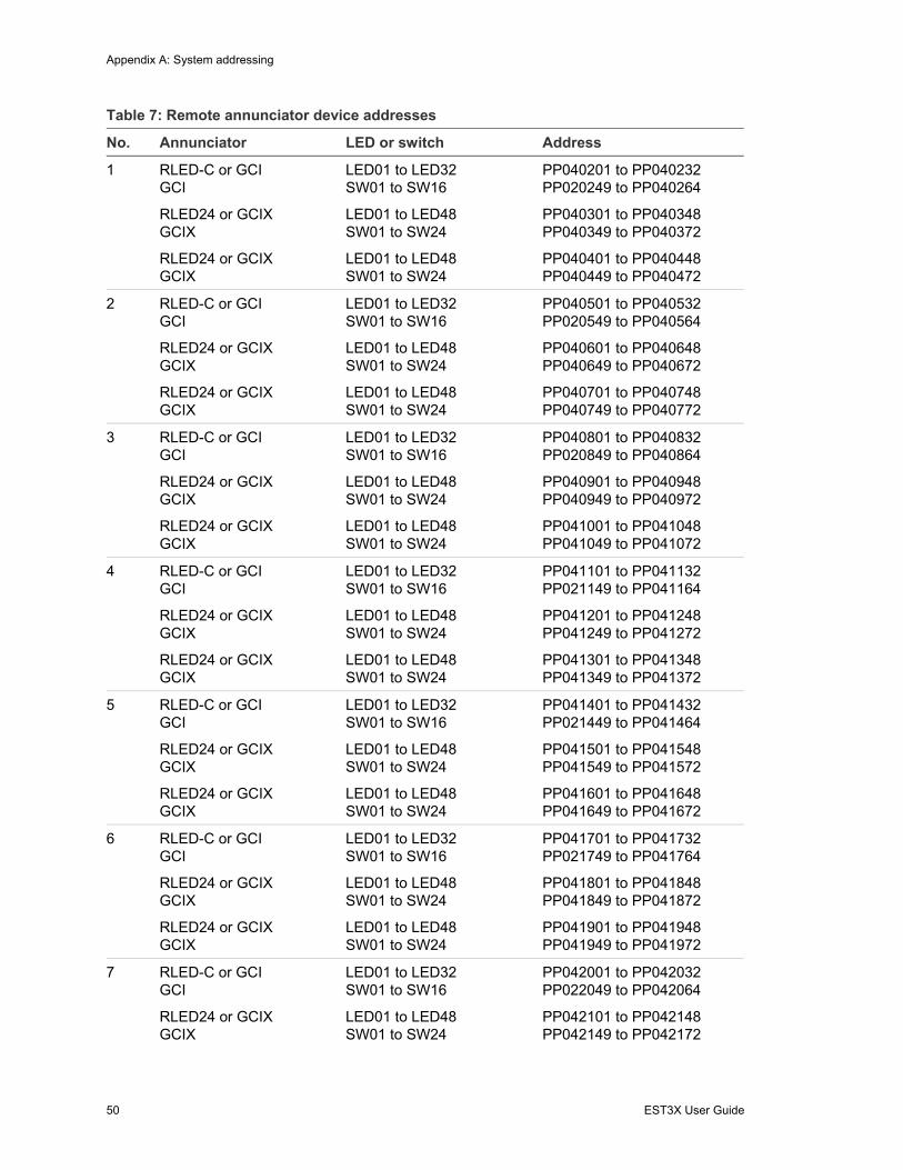
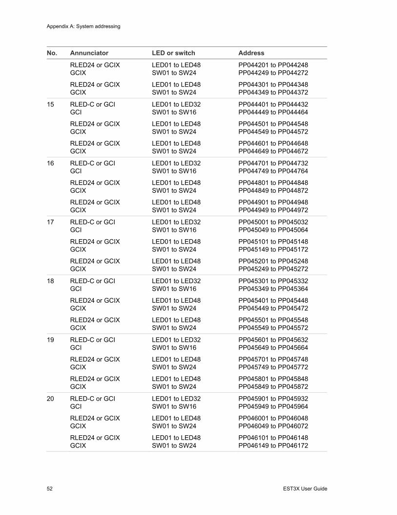
Remote annunciator device addresses
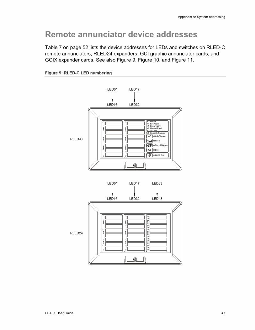
Table 7 on page 52 lists the device addresses for LEDs and switches on RLED-C remote annunciators, RLED24 expanders, GCI graphic annunciator cards, and GCIX expander cards. See also Figure 9, Figure 10, and Figure 11.
Figure 9: RLED-C LED numbering
Controls Enabled
Ack/Silence
Reset
Signal Silence
Drill
Lamp Test
PowerFire AlarmSupervisoryGround FaultTrouble
LED01
LED16
LED17
LED32
LED01
LED16
LED17
LED32
LED33
LED48
RLED-C
RLED24

Appendix A: System addressing
48 EST3X User Guide
Figure 10: GCI card LED and switch numbering
Supervisory LEDFire Alarm LED
Power LEDLamp Test LED
ACK/Panel Silence LEDEnable Controls LED
Trouble LEDGround Fault LED
Drill LEDSignal Silence LED
Reset LED
LED09LED10LED11LED12LED13LED14LED15LED16LED17LED18LED19LED20LED21LED22LED23LED24
SW16SW15SW14SW13SW12SW11SW10SW09SW08SW07SW06SW05LED32LED31LED30LED29LED28LED27LED26LED25
NOTUSED
LED01LED02LED03LED04LED05LED06LED07LED08ACK/Panel Silence SWReset SWSignal Silence SW
Drill SWLamp Test SW
SW04SW03SW02SW01
NOT USEDNOT USEDNOT USED
1 1 1 1
J1 J2 J3 J7
J4 J5 J6 J8
EXT SWSW1
1 1 1 1
GCI
J15

Appendix A: System addressing
EST3X User Guide 49
Figure 11: GCIX card LED and switch numbering
LED17
LED18LED19LED20LED21LED22LED23LED24SW01SW02SW03
SW04SW05
SW12SW11SW10SW09
SW06SW07SW08
LED16LED15LED14LED13LED12LED11
LED01LED02LED03
LED06
LED04
LED07
LED09
LED05
LED08
LED10
LED25LED26LED27LED28LED29LED30LED31LED32LED33LED34LED35LED36LED37LED38LED39LED40
SW24SW23SW22SW21SW20SW19SW18SW17SW16SW15SW14SW13LED48LED47LED46LED45LED44LED43LED42LED41
1 1 1 1
J1 J2 J3 J7
J4 J5 J6 J8
1 1 1 1
GCIX
Appendix A: System addressing
50 EST3X User Guide
Table 7: Remote annunciator device addresses
No. Annunciator LED or switch Address
1 RLED-C or GCI GCI
LED01 to LED32 SW01 to SW16
PP040201 to PP040232 PP020249 to PP040264
RLED24 or GCIX GCIX
LED01 to LED48 SW01 to SW24
PP040301 to PP040348 PP040349 to PP040372
RLED24 or GCIX GCIX
LED01 to LED48 SW01 to SW24
PP040401 to PP040448 PP040449 to PP040472
2 RLED-C or GCI GCI
LED01 to LED32 SW01 to SW16
PP040501 to PP040532 PP020549 to PP040564
RLED24 or GCIX GCIX
LED01 to LED48 SW01 to SW24
PP040601 to PP040648 PP040649 to PP040672
RLED24 or GCIX GCIX
LED01 to LED48 SW01 to SW24
PP040701 to PP040748 PP040749 to PP040772
3 RLED-C or GCI GCI
LED01 to LED32 SW01 to SW16
PP040801 to PP040832 PP020849 to PP040864
RLED24 or GCIX GCIX
LED01 to LED48 SW01 to SW24
PP040901 to PP040948 PP040949 to PP040972
RLED24 or GCIX GCIX
LED01 to LED48 SW01 to SW24
PP041001 to PP041048 PP041049 to PP041072
4 RLED-C or GCI GCI
LED01 to LED32 SW01 to SW16
PP041101 to PP041132 PP021149 to PP041164
RLED24 or GCIX GCIX
LED01 to LED48 SW01 to SW24
PP041201 to PP041248 PP041249 to PP041272
RLED24 or GCIX GCIX
LED01 to LED48 SW01 to SW24
PP041301 to PP041348 PP041349 to PP041372
5 RLED-C or GCI GCI
LED01 to LED32 SW01 to SW16
PP041401 to PP041432 PP021449 to PP041464
RLED24 or GCIX GCIX
LED01 to LED48 SW01 to SW24
PP041501 to PP041548 PP041549 to PP041572
RLED24 or GCIX GCIX
LED01 to LED48 SW01 to SW24
PP041601 to PP041648 PP041649 to PP041672
6 RLED-C or GCI GCI
LED01 to LED32 SW01 to SW16
PP041701 to PP041732 PP021749 to PP041764
RLED24 or GCIX GCIX
LED01 to LED48 SW01 to SW24
PP041801 to PP041848 PP041849 to PP041872
RLED24 or GCIX GCIX
LED01 to LED48 SW01 to SW24
PP041901 to PP041948 PP041949 to PP041972
7 RLED-C or GCI GCI
LED01 to LED32 SW01 to SW16
PP042001 to PP042032 PP022049 to PP042064
RLED24 or GCIX GCIX
LED01 to LED48 SW01 to SW24
PP042101 to PP042148 PP042149 to PP042172

Appendix A: System addressing
EST3X User Guide 51
No. Annunciator LED or switch Address
RLED24 or GCIX GCIX
LED01 to LED48 SW01 to SW24
PP042201 to PP042248 PP042249 to PP042272
8 RLED-C or GCI GCI
LED01 to LED32 SW01 to SW16
PP042301 to PP042332 PP022349 to PP042364
RLED24 or GCIX GCIX
LED01 to LED48 SW01 to SW24
PP042401 to PP042448 PP042449 to PP042472
RLED24 or GCIX GCIX
LED01 to LED48 SW01 to SW24
PP042501 to PP042548 PP042549 to PP042572
9 RLED-C or GCI GCI
LED01 to LED32 SW01 to SW16
PP042601 to PP042632 PP022649 to PP042664
RLED24 or GCIX GCIX
LED01 to LED48 SW01 to SW24
PP042701 to PP042748 PP042749 to PP042772
RLED24 or GCIX GCIX
LED01 to LED48 SW01 to SW24
PP042801 to PP042848 PP042849 to PP042872
10 RLED-C or GCI GCI
LED01 to LED32 SW01 to SW16
PP042901 to PP042932 PP022949 to PP042964
RLED24 or GCIX GCIX
LED01 to LED48 SW01 to SW24
PP043001 to PP043048 PP043049 to PP043072
RLED24 or GCIX GCIX
LED01 to LED48 SW01 to SW24
PP043101 to PP043148 PP043149 to PP043172
11 RLED-C or GCI GCI
LED01 to LED32 SW01 to SW16
PP043201 to PP043232 PP043249 to PP043264
RLED24 or GCIX GCIX
LED01 to LED48 SW01 to SW24
PP043301 to PP043348 PP043349 to PP043372
RLED24 or GCIX GCIX
LED01 to LED48 SW01 to SW24
PP043401 to PP043448 PP043449 to PP043472
12 RLED-C or GCI GCI
LED01 to LED32 SW01 to SW16
PP043501 to PP043532 PP043549 to PP043564
RLED24 or GCIX GCIX
LED01 to LED48 SW01 to SW24
PP043601 to PP043648 PP043649 to PP043672
RLED24 or GCIX GCIX
LED01 to LED48 SW01 to SW24
PP043701 to PP043748 PP043749 to PP043772
13 RLED-C or GCI GCI
LED01 to LED32 SW01 to SW16
PP043801 to PP043832 PP043849 to PP043864
RLED24 or GCIX GCIX
LED01 to LED48 SW01 to SW24
PP043901 to PP043948 PP043949 to PP043972
RLED24 or GCIX GCIX
LED01 to LED48 SW01 to SW24
PP044001 to PP044048 PP044049 to PP044072
14 RLED-C or GCI GCI
LED01 to LED32 SW01 to SW16
PP044101 to PP044132 PP044149 to PP044164
Appendix A: System addressing
52 EST3X User Guide
No. Annunciator LED or switch Address
RLED24 or GCIX GCIX
LED01 to LED48 SW01 to SW24
PP044201 to PP044248 PP044249 to PP044272
RLED24 or GCIX GCIX
LED01 to LED48 SW01 to SW24
PP044301 to PP044348 PP044349 to PP044372
15 RLED-C or GCI GCI
LED01 to LED32 SW01 to SW16
PP044401 to PP044432 PP044449 to PP044464
RLED24 or GCIX GCIX
LED01 to LED48 SW01 to SW24
PP044501 to PP044548 PP044549 to PP044572
RLED24 or GCIX GCIX
LED01 to LED48 SW01 to SW24
PP044601 to PP044648 PP044649 to PP044672
16 RLED-C or GCI GCI
LED01 to LED32 SW01 to SW16
PP044701 to PP044732 PP044749 to PP044764
RLED24 or GCIX GCIX
LED01 to LED48 SW01 to SW24
PP044801 to PP044848 PP044849 to PP044872
RLED24 or GCIX GCIX
LED01 to LED48 SW01 to SW24
PP044901 to PP044948 PP044949 to PP044972
17 RLED-C or GCI GCI
LED01 to LED32 SW01 to SW16
PP045001 to PP045032 PP045049 to PP045064
RLED24 or GCIX GCIX
LED01 to LED48 SW01 to SW24
PP045101 to PP045148 PP045149 to PP045172
RLED24 or GCIX GCIX
LED01 to LED48 SW01 to SW24
PP045201 to PP045248 PP045249 to PP045272
18 RLED-C or GCI GCI
LED01 to LED32 SW01 to SW16
PP045301 to PP045332 PP045349 to PP045364
RLED24 or GCIX GCIX
LED01 to LED48 SW01 to SW24
PP045401 to PP045448 PP045449 to PP045472
RLED24 or GCIX GCIX
LED01 to LED48 SW01 to SW24
PP045501 to PP045548 PP045549 to PP045572
19 RLED-C or GCI GCI
LED01 to LED32 SW01 to SW16
PP045601 to PP045632 PP045649 to PP045664
RLED24 or GCIX GCIX
LED01 to LED48 SW01 to SW24
PP045701 to PP045748 PP045749 to PP045772
RLED24 or GCIX GCIX
LED01 to LED48 SW01 to SW24
PP045801 to PP045848 PP045849 to PP045872
20 RLED-C or GCI GCI
LED01 to LED32 SW01 to SW16
PP045901 to PP045932 PP045949 to PP045964
RLED24 or GCIX GCIX
LED01 to LED48 SW01 to SW24
PP046001 to PP046048 PP046049 to PP046072
RLED24 or GCIX GCIX
LED01 to LED48 SW01 to SW24
PP046101 to PP046148 PP046149 to PP046172

Appendix A: System addressing
EST3X User Guide 53
No. Annunciator LED or switch Address
21 RLED-C or GCI GCI
LED01 to LED32 SW01 to SW16
PP046201 to PP046232 PP046249 to PP046264
RLED24 or GCIX GCIX
LED01 to LED48 SW01 to SW24
PP046301 to PP046348 PP046349 to PP046372
RLED24 or GCIX GCIX
LED01 to LED48 SW01 to SW24
PP046401 to PP046448 PP046449 to PP046472
22 RLED-C or GCI GCI
LED01 to LED32 SW01 to SW16
PP046501 to PP046532 PP046549 to PP046564
RLED24 or GCIX GCIX
LED01 to LED48 SW01 to SW24
PP046601 to PP046648 PP046649 to PP046672
RLED24 or GCIX GCIX
LED01 to LED48 SW01 to SW24
PP046701 to PP046748 PP046749 to PP046772
23 RLED-C or GCI GCI
LED01 to LED32 SW01 to SW16
PP046801 to PP046832 PP046849 to PP046864
RLED24 or GCIX GCIX
LED01 to LED48 SW01 to SW24
PP046901 to PP046948 PP046949 to PP046972
RLED24 or GCIX GCIX
LED01 to LED48 SW01 to SW24
PP047001 to PP047048 PP047049 to PP047072
24 RLED-C or GCI GCI
LED01 to LED32 SW01 to SW16
PP047101 to PP047132 PP047149 to PP047164
RLED24 or GCIX GCIX
LED01 to LED48 SW01 to SW24
PP047201 to PP047248 PP047249 to PP047272
RLED24 or GCIX GCIX
LED01 to LED48 SW01 to SW24
PP047301 to PP047348 PP047349 to PP047372
25 RLED-C or GCI GCI
LED01 to LED32 SW01 to SW16
PP047401 to PP047432 PP047449 to PP047464
RLED24 or GCIX GCIX
LED01 to LED48 SW01 to SW24
PP047501 to PP047548 PP047549 to PP047572
RLED24 or GCIX GCIX
LED01 to LED48 SW01 to SW24
PP047601 to PP047648 PP047649 to PP047672
26 RLED-C or GCI GCI
LED01 to LED32 SW01 to SW16
PP047701 to PP047732 PP047749 to PP047764
RLED24 or GCIX GCIX
LED01 to LED48 SW01 to SW24
PP047801 to PP047848 PP047849 to PP047872
RLED24 or GCIX GCIX
LED01 to LED48 SW01 to SW24
PP047901 to PP047948 PP047949 to PP047972
27 RLED-C or GCI GCI
LED01 to LED32 SW01 to SW16
PP048001 to PP048032 PP048049 to PP048064
RLED24 or GCIX GCIX
LED01 to LED48 SW01 to SW24
PP048101 to PP048148 PP048149 to PP048172

Appendix A: System addressing
54 EST3X User Guide
No. Annunciator LED or switch Address
RLED24 or GCIX GCIX
LED01 to LED48 SW01 to SW24
PP048201 to PP048248 PP048249 to PP048272
28 RLED-C or GCI GCI
LED01 to LED32 SW01 to SW16
PP048301 to PP048332 PP048349 to PP048364
RLED24 or GCIX GCIX
LED01 to LED48 SW01 to SW24
PP048401 to PP048448 PP048449 to PP048472
RLED24 or GCIX GCIX
LED01 to LED48 SW01 to SW24
PP048501 to PP048548 PP048549 to PP048572
29 RLED-C or GCI GCI
LED01 to LED32 SW01 to SW16
PP048601 to PP048632 PP048649 to PP048664
RLED24 or GCIX GCIX
LED01 to LED48 SW01 to SW24
PP048701 to PP048748 PP048749 to PP048772
RLED24 or GCIX GCIX
LED01 to LED48 SW01 to SW24
PP048801 to PP048848 PP048849 to PP048872
30 RLED-C or GCI GCI
LED01 to LED32 SW01 to SW16
PP048901 to PP048932 PP048949 to PP048964
RLED24 or GCIX GCIX
LED01 to LED48 SW01 to SW24
PP049001 to PP049048 PP049049 to PP049072
RLED24 or GCIX GCIX
LED01 to LED48 SW01 to SW24
PP049101 to PP049148 PP049149 to PP049172
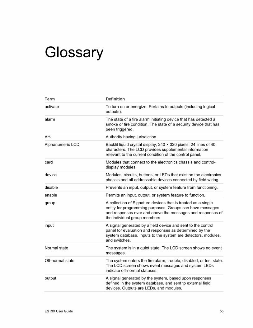
EST3X User Guide 55
Glossary
Term Definition
activate To turn on or energize. Pertains to outputs (including logical outputs).
alarm The state of a fire alarm initiating device that has detected a smoke or fire condition. The state of a security device that has been triggered.
AHJ Authority having jurisdiction.
Alphanumeric LCD Backlit liquid crystal display, 240 × 320 pixels, 24 lines of 40 characters. The LCD provides supplemental information relevant to the current condition of the control panel.
card Modules that connect to the electronics chassis and control-display modules.
device Modules, circuits, buttons, or LEDs that exist on the electronics chassis and all addressable devices connected by field wiring.
disable Prevents an input, output, or system feature from functioning.
enable Permits an input, output, or system feature to function.
group A collection of Signature devices that is treated as a single entity for programming purposes. Groups can have messages and responses over and above the messages and responses of the individual group members.
input A signal generated by a field device and sent to the control panel for evaluation and responses as determined by the system database. Inputs to the system are detectors, modules, and switches.
Normal state The system is in a quiet state. The LCD screen shows no event messages.
Off-normal state The system enters the fire alarm, trouble, disabled, or test state. The LCD screen shows event messages and system LEDs indicate off-normal statuses.
output A signal generated by the system, based upon responses defined in the system database, and sent to external field devices. Outputs are LEDs, and modules.

Glossary
56 EST3X User Guide
pseudo point An input or output point that is not a physical device. For example, ground fault and communication fault notifications.
reset Refers to a condition of an input, where the input is not active. It also refers to the condition of an output where the output is not in its SET or RESET condition and does not have a priority value associated with it.
rotary controller A multifunctional control dial that performs the functions of a computer keyboard and the Enter key. The controller is used to scroll through and select events, menus, and commands and to enter addresses.
RS-232 A serial communications format normally used for serial peripheral devices (i.e., printers) from a computer.
SDU System Definition Utility. A Windows-based program used to enter and modify information contained in the system.

EST3X User Guide 57
Index
A
Acknowledge button, 22 acknowledging events, 22 addresses
backspacing, 12 alarm
report, 16 alarm count, 19 Alarm Silence button, 21 All Active points report, 16 Alternate Sensitivity, 26
B
backspacing, 12 basic function, 8 buzzer, 20 bypass
sensor messages, 32 bypassing photo element, 32
C
capabilities, 2 carbon monoxide detection, 32
change rate, 33 restore rate, 33
changing alarm sensitivity, 26 CO detection rate, 33 event message routes, 26
CO detection, 32 change rate, 33 restore rate, 33
D
database download, 29
device disable, 27 drill, 23
device (continued) enable, 27 maintenance report, 17
disabled points report, 16
disabling devices, 27 zones, 28
displaying device maintenance reports, 17
download database, 29
drill perform, 23
E
enabling devices, 27 zone groups, 28
event messages, 9
F
finding database versions, 18 finding firmware versions, 18
G
Gas Accel command, 32 gateway address, 19 guard patrol routes, 31
activate, 31 restore, 31
H
history reports, 18
I
IP address, 19

Index
58 EST3X User Guide
L
lamp test, 22 listed services, 2
M
maintenance device report, 17 preventive, 36 routine schedule, 38 schedules, 36 service provider, 36 tests, 36 visual inspection schedule, 37
microphone local, 13
monitor report, 16
O
Outputs report, 16 overview
controls and indicators, 4 system, 2
P
page function buttons, 13 paging
local microphone, 13 panel buzzer, 20 Panel Silence button, 20 previous screen, 12 Primary Sensitivity, 26 printing
device maintenance reports, 17 PTT button, 13
R
Remote Read Lock, 30 Remote Write Unlock, 29 reports
device maintenance, 17 Reset button, 22 rotary controller, 11
S
schedule routine maintenance, 38 visual inspection, 37
screen language, 23
selecting alternate alarm sensitivity, 26 commands, 11 menus, 11 primary alarm sensitivity, 26
sensor bypass messages, 32 restore messages, 32
service provider, 36 setting time and date, 28 silencing
alarm signals, 21 panel buzzer, 20
Status menu commands Alarm, 16 All Active, 16 Disabled Points, 16 Monitor, 16 Outputs, 16 Supervisory, 16 Test, 16 Trouble, 16
status reports, 16 subnet mask, 19 supervisory
report, 16 system
capabilities, 2 operation, 8 overview, 2 reset, 22 service provider, 36
T
TCP/IP communications, 30 TCP/IP settings, 19 test
lamp test, 22 preventive maintenance, 36 report, 16
trouble report, 16
troubleshooting, 39
U
user access levels, 10 user time out period, 10
V
viewing status reports, 16
viewing event messages, 9

Index
EST3X User Guide 59
Z
zone disable, 28
zone groups enable, 28

Index
60 EST3X User Guide