3100 series jamb seals: santoprene control … - 3100 - may 2015.… · control dampers & fire...
TRANSCRIPT
CONTROL DAMPERS & FIRE DAMPERS
3100 SERIES AIRFOIL BLADE • EXTRUDED ALUM. CONTROL DAMPERS
3160 | 3161 | 3165
DWG. 3100 MAY 2015
195 HEALEY ROAD | BOLTON, ON. L7E 5B2 | TEL (905) 857-4700 | FAX (905) 857-4730 | 1-800-668-7214 | www.ventexinc.com
[1]
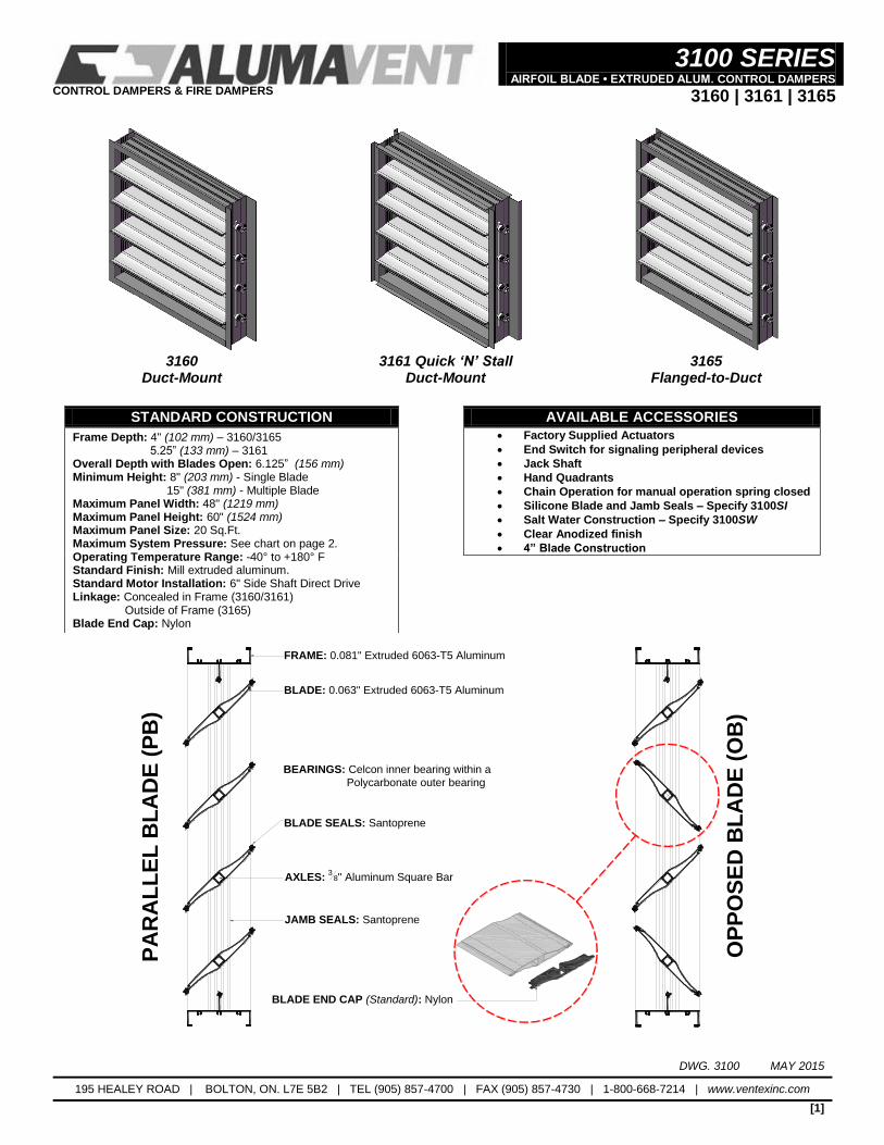
3160
Duct-Mount 3161 Quick ‘N’ Stall
Duct-Mount 3165
Flanged-to-Duct
STANDARD CONSTRUCTION AVAILABLE ACCESSORIES
Frame Depth: 4" (102 mm) – 3160/3165 5.25” (133 mm) – 3161 Overall Depth with Blades Open: 6.125” (156 mm) Minimum Height: 8" (203 mm) - Single Blade 15" (381 mm) - Multiple Blade Maximum Panel Width: 48" (1219 mm) Maximum Panel Height: 60" (1524 mm) Maximum Panel Size: 20 Sq.Ft. Maximum System Pressure: See chart on page 2. Operating Temperature Range: -40° to +180° F Standard Finish: Mill extruded aluminum. Standard Motor Installation: 6" Side Shaft Direct Drive Linkage: Concealed in Frame (3160/3161) Outside of Frame (3165) Blade End Cap: Nylon
Factory Supplied Actuators
End Switch for signaling peripheral devices
Jack Shaft
Hand Quadrants
Chain Operation for manual operation spring closed
Silicone Blade and Jamb Seals – Specify 3100SI
Salt Water Construction – Specify 3100SW
Clear Anodized finish
4” Blade Construction
FRAME: 0.081" Extruded 6063-T5 Aluminum
BLADE: 0.063" Extruded 6063-T5 Aluminum
JAMB SEALS: Santoprene
BLADE SEALS: Santoprene
AXLES: 3
8" Aluminum Square Bar
PA
RA
LL
EL
BL
AD
E (
PB
)
OP
PO
SE
D B
LA
DE
(O
B)
BEARINGS: Celcon inner bearing within a
Polycarbonate outer bearing
BLADE END CAP (Standard): Nylon
CONTROL DAMPERS & FIRE DAMPERS
3100 SERIES AIRFOIL BLADE • EXTRUDED ALUM. CONTROL DAMPERS
3160 | 3161 | 3165
DWG. 3100 MAY 2015
195 HEALEY ROAD | BOLTON, ON. L7E 5B2 | TEL (905) 857-4700 | FAX (905) 857-4730 | 1-800-668-7214 | www.ventexinc.com
[2]
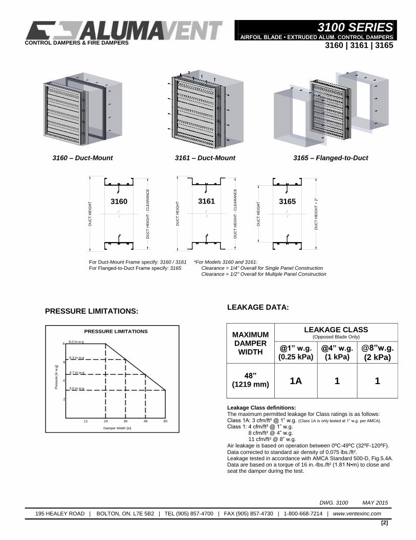
3160 – Duct-Mount 3161 – Duct-Mount 3165 – Flanged-to-Duct
31653160 3161
For Duct-Mount Frame specify: 3160 / 3161
For Flanged-to-Duct Frame specify: 3165
DU
CT
HE
IGH
T
DU
CT
HE
IGH
T -
CLE
AR
AN
CE
*For Models 3160 and 3161:
Clearance = 1/4" Overall for Single Panel Construction
Clearance = 1/2" Overall for Multiple Panel Construction
DU
CT
HE
IGH
T
DU
CT
HE
IGH
T -
CLE
AR
AN
CE
DU
CT
HE
IGH
T
DU
CT
HE
IGH
T +
2"
PRESSURE LIMITATIONS:
2
6
8
4
8.0 in w.g
6.3 in w.g
4.7 in w.g
3.0 in w.g
Damper Width [in]
Pre
ssure
[in
w.g
]
12 24 36 48 60
PRESSURE LIMITATIONS
LEAKAGE DATA:
Leakage Class definitions: The maximum permitted leakage for Class ratings is as follows: Class 1A: 3 cfm/ft² @ 1” w.g. (Class 1A is only tested at 1” w.g. per AMCA). Class 1: 4 cfm/ft² @ 1” w.g. 8 cfm/ft² @ 4” w.g. 11 cfm/ft² @ 8” w.g. Air leakage is based on operation between 0⁰C-49⁰C (32⁰F-120⁰F).
Data corrected to standard air density of 0.075 lbs./ft². Leakage tested in accordance with AMCA Standard 500-D, Fig.5.4A. Data are based on a torque of 16 in.-lbs./ft² (1.81 N•m) to close and seat the damper during the test.
MAXIMUM DAMPER WIDTH
LEAKAGE CLASS (Opposed Blade Only)
@1” w.g. (0.25 kPa)
@4” w.g. (1 kPa)
@8”w.g. (2 kPa)
48” (1219 mm)
1A 1 1
CONTROL DAMPERS & FIRE DAMPERS
3100 SERIES AIRFOIL BLADE • EXTRUDED ALUM. CONTROL DAMPERS
3160 | 3161 | 3165
DWG. 3100 MAY 2015
195 HEALEY ROAD | BOLTON, ON. L7E 5B2 | TEL (905) 857-4700 | FAX (905) 857-4730 | 1-800-668-7214 | www.ventexinc.com
[3]
PRESSURE DROP:
Tested to AMCA Figure 5.3 (Ducted both sides):
12 x 12 (305 x 305) 24 x 24 (610 x 610) 36 x 36 (914 x 914) 48 x 12 (1219 x 305) 12 x 48 (305 x 1219) Velocity
(fpm) Pressure Drop
(in. w.g.) Velocity
(fpm)Pressure Drop
(in. w.g.)Velocity
(fpm)Pressure Drop
(in. w.g.)Velocity
(fpm)Pressure Drop
(in. w.g.)Velocity
(fpm)Pressure Drop
(in. w.g.)
505 0.011 518 0.008 496 0.004 499 0.007 499 0.005
1001 0.040 990 0.028 1004 0.020 1003 0.027 1004 0.021
1463 0.091 1497 0.061 1495 0.043 1498 0.062 1504 0.048
1958 0.174 2010 0.103 1994 0.070 2002 0.116 2006 0.086
3004 0.422 3016 0.237 3001 0.165 3003 0.267 3001 0.197
Tested to AMCA Figure 5.5 (Inlet chamber, no outlet duct):
12 x 12 (305 x 305) 24 x 24 (610 x 610) 36 x 36 (914 x 914) 48 x 12 (1219 x 305) 12 x 48 (305 x 1219) Velocity
(fpm) Pressure Drop
(in. w.g.) Velocity
(fpm)Pressure Drop
(in. w.g.)Velocity
(fpm)Pressure Drop
(in. w.g.)Velocity
(fpm)Pressure Drop
(in. w.g.)Velocity
(fpm)Pressure Drop
(in. w.g.)
489 0.051 531 0.055 496 0.045 572 0.052 608 0.086
996 0.196 1013 0.205 1004 0.185 1217 0.248 1241 0.359
1495 0.435 1513 0.467 1497 0.411 1795 0.558 1781 0.737
1986 0.767 2019 0.846 1999 0.741 2443 1.083 2443 1.393
3036 1.805 3004 1.887 3005 1.681 3014 1.758 3001 2.105
Pressure drop tested per AMCA 500-D per set-up figures as indicated above. Data corrected to standard air density of 0.075 lbs/ft³.
RECOMMENDED SPECIFICATION:
Furnish and install control damper model 3160 / 3161 / 3165 as manufactured by Alumavent Inc., Bolton Ontario. Blades shall be 0.063” (1.60 mm) thick extruded aluminum, hollow airfoil shape. Frames shall be 0.081” (2.06 mm) thick extruded aluminum. Axles shall be 0.375” (9.53 mm) aluminum square bar. Blade and Jamb seals shall be Santoprene (or optional Silicone). Linkage is concealed in frame for models 3160 / 3161 and outside of frame for model 3165. Operating temperature range shall be -40° to +180°F. Leakage and pressure drop performance data submitted to be based on tests in accordance with AMCA Standard 500-D. Dampers must comply with the requirements of AMCA 511 Certified Ratings Program and be qualified to bear the AMCA Seal for Air Performance and Air Leakage. Damper widths from 12” (305 mm) to 48” (1219 mm) must meet leakage Class 1A criteria of maximum 3 cfm/ft² (15.2 L/s/m²) at 1” w.g. (.25 kPa).
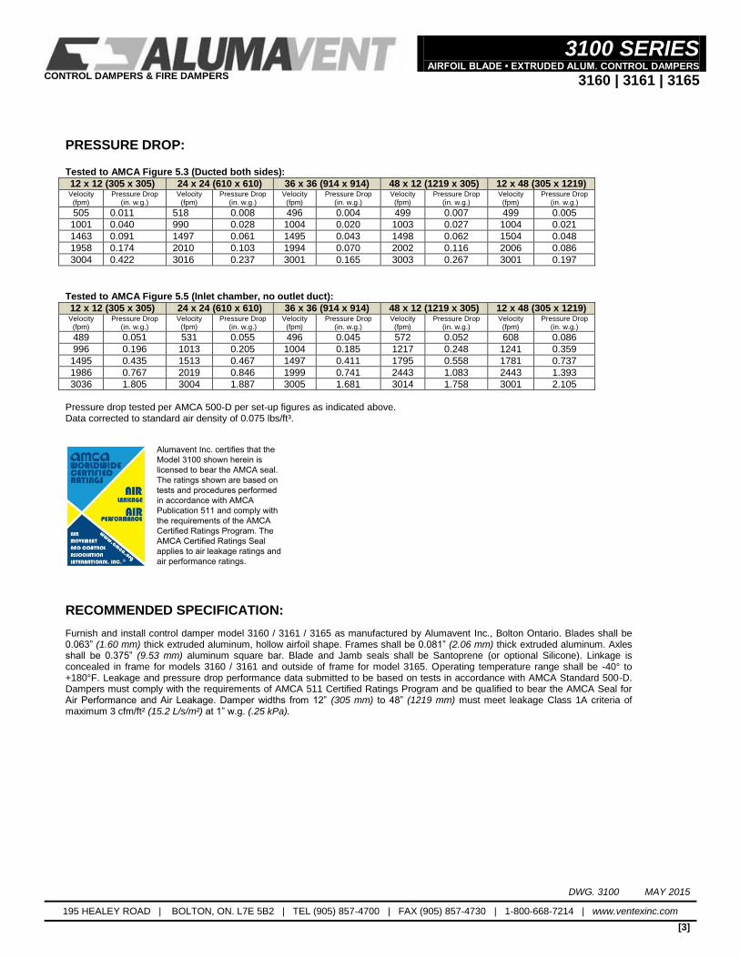
Alumavent Inc. certifies that the Model 3100 shown herein is licensed to bear the AMCA seal. The ratings shown are based on tests and procedures performed in accordance with AMCA Publication 511 and comply with the requirements of the AMCA Certified Ratings Program. The AMCA Certified Ratings Seal applies to air leakage ratings and air performance ratings.