3.1 facility requirements - arizona dot facility requirements ... the following subparagraphs...
TRANSCRIPT

I I I
i i !i : , :
: CASA GRANDE MUNICIPAL ~ O R T MASTER PLAN
CHAPTER 3 : F I REQUIREMENTS •
I I I I I I I I I I I I I I I I
3.1 FACILITY REQUIREMENTS
The facility requirements chapter of this report defines the physical facilities needed to safely and efficiently accommodate the current and future aviation demands at the Casa Grande Municipal Airport. The aviation forecasts discussed in the previous sections are used as the basis for determining the physical requirements such as pavement, buildings, and support facilities needed to meet the aviation needs of the community through the next twenty year period. Facilities discussed in this section include the runway, taxiway, tiedowns, hangars, apron, navigational aids, and miscellaneous facilities.
Although the required developments are defined in specific time flames, it is necessary to continually review the activity levels achieved. For example, if the number of operations and based aircraft forecast increase more rapidly than indicated, the time frame for development would also be accelerated. Likewise, if the number of operations or based aircraft should decrease, the time frame for development would be delayed. For the community of Casa Grande we have developed a matrix identifying events which on occurrence cause acceleration. Utilization of this matrix allows the Casa Grande Municipal Airport to respond to demand driven tangible requirements and not arbitrary time frames.
3.2 AIRFIELD REQUIREMENTS
Airfield requirements include the need for those facilities related to the arrival and departure of aircraft. These facilities are Runways, taxiways, Airfield marking and lighting, and navigational aids.
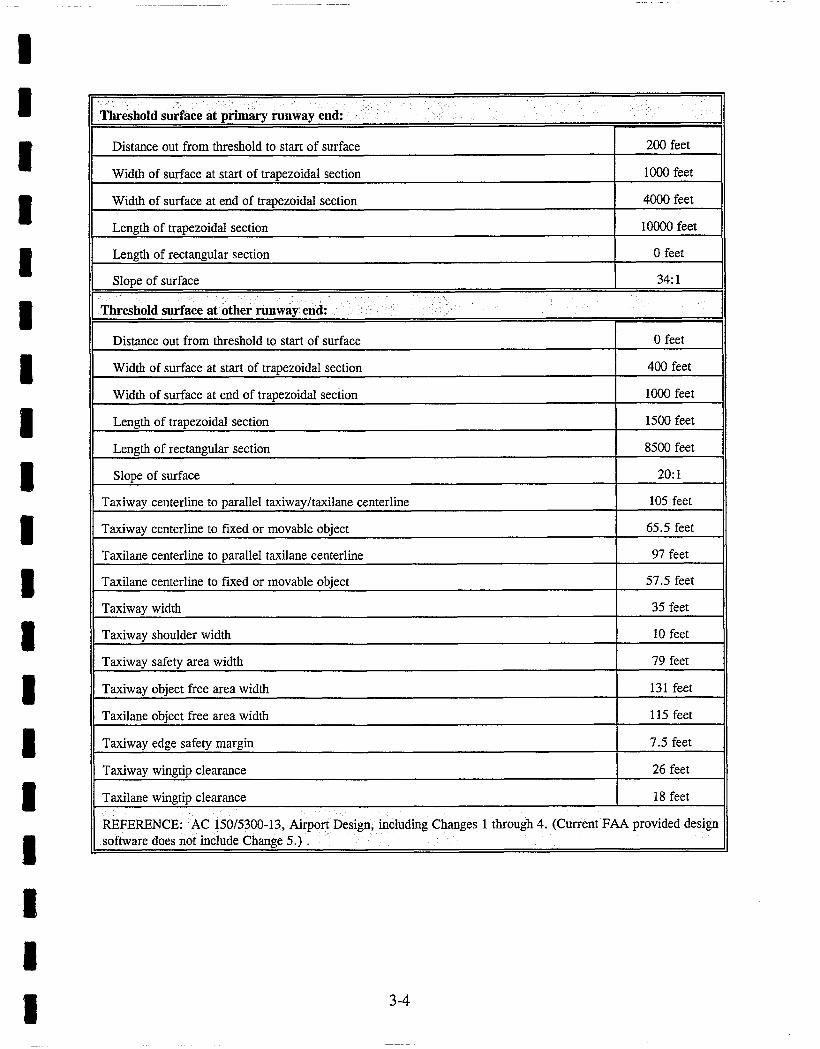
The selection of the appropriate FAA design standards for the development of airfield facilities is based on the characteristics of the critical aircraft. As previously discussed in Chapter 2, Forecasts, the critical aircraft is defined as an Airport Reference Code of D-II. Table 3.1 Dimensional Design Standards illustrates the design standards described in FAA Advisory Circular 150/5300-13, Change 5.
3-1

I I TABLE 3.1
I I i I I I I I I I I I I I I I
[ ~ O R T DESIGN AIRPLANE AND ~ o R T DATA Ii.
Aircraft Approach Category D or E Airplane Design Group II I
Airplane wingspan 78.99 feet I I
, Primary runway end approach visibility minimums are not lower than CAT I I II
Other runway end approach visibility minimums are visual exclusively 1 i [ i
Airplane undercarriage width (1.15 x main gear track) 16.10 feet I I I I
Airport elevation 1462 feet i, ! I
, Airplane tail height 24.40 feet i i i i : !
RUNWAY AND TAXIWAY WIDTH AND CLEARANCE STANDARD DIMENSIONS
Airplane Group/ARC i [
Runway centerline to parallel runway centerline simultaneous operations when wake turbulence is not treated as a factor:
i i
VFR operations with no intervening taxiway 700 feet | i i
VFR operations with one intervening taxiway 800 feet 1
VFR operations with two intervening taxiways 905 feet i
IFR approach and departure with approach to near threshold 2500 feet less 100 ft for each 500 fl of threshold stagger to a minimum of 1000 feet.
Runway centerline to parallel runway centerline simultaneous operations when wake turbulence is treated as a factor:
i i J
VFR operations 2500 feet i i i
IFR departures 2500 feet | i t
IFR approach and departure with approach to near threshold 2500 feet i i i
IFR approach and departure with approach to far threshold 2500 feet plus 100 feet for each 500 feet of threshold stagger
IFR approaches 3400 feet i i
Runway centerline to parallel taxiway/taxilane centerline ! 400 feet
Runway centerline to edge of aircraft parking 500 feet
! 1 ' , Runway width 100 feet , I I
Runway shoulder width i 10 feet :
~ Runway blast pad width 120 feet ii i i
Runway blast pad length 150 feet ii i J
.. Runway safety area width 520 feet
I 3-2

I I I I I
Runway safety area length beyond each runway end or stopway end, whichever is greater 1000 feet
Runway object free area width 800 feet
Runway object free area length beyond each runway end or stopway end, whichever is 1000 feet greater
Clearway width 500 feet
Stopway width 100 feet
Obstacl f r e e (OFZ): e zone ,
Runway OFZ width 400 feet
Runway OFZ length beyond each runway end 200 feet
Inner-approach OFZ width 400 feet
Inner-approach OFZ length beyond approach light system 200 feet
Inner-approach OFZ slope from 200 feet beyond threshold 50:1
Inner-transitional OFZ height H 49.2 feet
I I I I
Inner-transitional OFZ slope 6:1
Runway protection zone at the primary runway end:
I I
Width 200 feet from runway end
Width 2700 feet from runway end
Length
1000 feet
1750 feet
2500 feet
Runway protection zone at other runway end:
I I
Width 200 feet from runway end
Width 1900 feet from nmway end
Length
500 feet
1010 feet
1700 feet
Departure runway protection zone:
I Width 200 feet from the far end of TORA 500 feet
1010 feet
! Width 1900 feet from the far end of TORA
Length 1700 feet
I I I I 3-3
I I I I I I I I I I l I I I l I
Distance out from threshold to start of surface 200 feet 41
Width of surface at start of trapezoidal section 1000 feet t l
Width of surface at end of trapezoidal section 4000 feet I I
Length of trapezoidal section 10000 feet I I
Length of rectangular section 0 feet I I
Slope of surface 34:1
Threshold surface at other runway end:
Distance out from threshold to start of surface 0 feet
Width of surface at start of trapezoidal section 400 feet i,
Width of surface at end of trapezoidal seciion 1000 feet
Length of trapezoidal section 1500 feet II
i
Length of rectangular section 8500 feet . II
Slope of surface 20:1 t
Taxiway centerline to parallel taxiway/taxilane centerline 105 feet I
Taxiway centerline to fixed or movable object 65.5 feet I
Taxilane centerline to parallel taxilane centerline 97 feet I
Taxilane centerline to fixed or movable object 57.5 feet 1
Taxiway width 35 feet I
Taxiway shoulder width 10 feet I
Taxiway safety area width 79 feet I
Taxiway object free area width 131 feet I
Taxilane object free area width 115 feet t
Taxiway edge safety margin 7.5 feet i
Taxiway wingtip clearance 26 feet i
Taxilane wingtip clearance 18 feet I
REFERENCE: AC 150/5300-13, Airport Design, including Changes 1 through 4. (Current FAA provided design software does not include Change 5.) . . . .
I I I 3-4

I I I I I I I I I I I I I I I I I I I
3.3 RUNWAY
The following subparagraphs address planning issues relating to runway orientation, and runway length.
3.3.1 RUNWAY ORIENTATION
For planning and design, a cross wind component is considered excessive at 10.5 knots for aircraft under 12,500 pounds gross takeoff weight and listed in ARC A-I and B-I, 12 knots for aircraft over 12,500 pounds in ARC A-II and B-II, and 16 knots for aircraft in ARC A-lit, B- III and C-I through D-HI. FAA design criteria allows a primary runway to accommodate a crosswind coverage up to and over 95 % with out a crosswind runway.
The runway orientation is determined by the direction of the prevailing winds. The current wind rose for the Casa Grande Airport identifies a 99.6% coverage with a 13 knot crosswind. A 13 knot crosswind coverage is required for the current Airport Reference Code conditions. An analysis of the wind rose reveals that a greater wind coverage is achieved with the 16 knot crosswind required for the critical aircraft ARC D-II. Therefore, a crosswind runway does not appear to be required under the current wind conditions.
3.3.2 RUNWAY LENGTH
The determination of runway length requirements is based on five primary factors: airport elevation, mean maximum daily temperature of the hottest month, runway gradient, critical aircraft, and the length of the longest haul.
Advisory Circular 150/5325-4A, entitled Runway Length Requirements for Airport Design, divides aircraft into two groups for the purpose of determining runway length. These basic groups include: 1) airplanes up to and including 60,000 pounds; and 2) airplanes over 60,000 pounds.
This group of airplanes is further broken down into the following subgroups: 1) airplanes with approach speeds less than 30 knots; 2) airplanes with approach speeds of 30 knots or more but less than 50 knots; 3) airplanes with approach speeds of 50 knots or more and Maximum Certificated Takeoff Weight of 12,500 pounds or less; 4) all airplanes with Maximum Certificated Takeoff Weight of more than 12,500 pounds and up to and including 60,000 pounds. The majority of the aircraft using the Casa Grande Municipal Airport fall into subgroup 3 or 4 however the ultimate critical aircraft would be in the category over 60,000 pounds. It is recommended that the pavement section design of any proposed projects consider the weight of the ultimate critical aircraft. A Grumman Gulfstream IV is a common corporate aircraft that is in the ARC D-II group of aircraft. The maximum takeoff weigh is 78,000 lbs.
3-5
I I I I
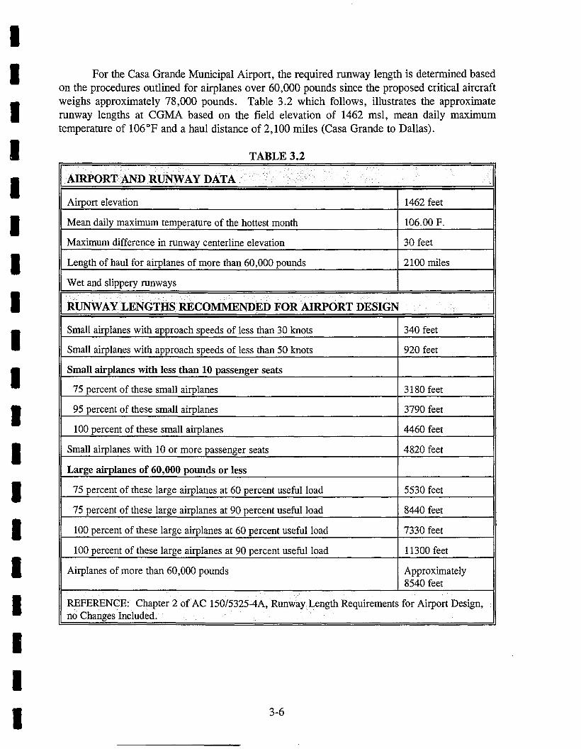
For the Casa Grande Municipal Airport, the required runway length is determined based on the procedures outlined for airplanes over 60,000 pounds since the proposed critical aircraft weighs approximately 78,000 pounds. Table 3.2 which follows, illustrates the approximate runway lengths at CGMA based on the field elevation of 1462 msl, mean daily maximum temperature of 106 °F and a haul distance of 2,100 miles (Casa Grande to Dallas).
TABLE 3.2
I I I I I I I I I i I I
Airport elevation 1462 feet
Mean daily maximum temperature of the hottest month 106.00 F.
Maximum difference in runway centerline elevation 30 feet
Length of haul for airplanes of more than 60,000 pounds 2100 miles
Wet and slippery runways . . . .
RUNWAY LENGTHS RECOMMENDED FOR AIRPORT DESIGN
Small airplanes with approach speeds of less than 30 knots 340 feet
Small airplanes with approach speeds of less than 50 knots 920 feet
Small airplanes with less than 10 passenger seats
75 percent of these small airplanes 3180 feet
95 percent of these small airplanes 3790 feet
100 percent of these small airplanes 4460 feet
Small airplanes with 10 or more passenger seats 4820 feet
Large airplanes of 60,000 pounds or less
75 percent of these large airplanes at 60 percent useful load 5530 feet
75 percent of these large airplanes at 90 percent useful load 8440 feet
100 percent of these large airplanes at 60 percent useful load 7330 feet
100 percent of these large airplanes at 90 percent useful load 11300 feet
Airplanes of more than 60,000 pounds Approximately 8540 feet
REFERENCE: Chapter 2 of AC 150/5325-4A, Runway Length Requirements for Airport Design, no Changes Included.
I I I 3-6

I I I I I I I I I I I I I I i I I I I
Utilizing the above table from the FAA Advisory Circular for Runway lengths, an ultimate runway length of 8540' is recommended to meet the needs of the critical aircraft, which is weighs in excess of 60,000 pounds. This length would also provide adequate runway length to serve 75 % of large airplanes less than 60,000 pounds at a 90 % useful load.
3.4 PAVEMENT STRENGTH
The current paving section at the Casa Grande Airport utilizes a 5" bituminous surface on a 12" crushed aggregate base. This configuration yields a pavement strength of 18,500 pounds single wheel loading and 65,000 pounds dual wheel loading. This pavement thickness is considered adequate for the type of aircraft currently using the airport. The pavement section should consider a full strength design, but it may be necessary to construct the pavement in a phased construction program. For example, if the full strength pavement required a 6 inch pavement with a 12 inch base, consideration should be given to constructing the 12 inch base, and only putting on a 4 or 5 inch pavement surface, until there is sufficient justification and need to provide the additional strength when the ultimate critical aircraft conditions are met.
The strength of the taxiway system is less than the design strength of the runway. It is recommended that future construction or reconstruction of the taxiways consider the design strengths of the runway to accommodate the future design aircraft. Further, the existing separation between the Runway 5-23 and parallel Taxiway B meets current FAA criteria for B-II ARC. Future construction should provide additional spacing between the runway and taxiway to meet the criteria established for D-II aircraft which is currently 400 feet.
The existing pavement condition of the Casa Grande Airport was inventoried by the City of Casa Grande. The results of this survey indicate a Pavement Condition Index of 85 which is considered Good. However, continuous pavement maintenance needs to be completed on a regular basis to maximize the life of the pavements. The complete results of this survey are included in Appendix 3.1.
3.5 TAXIWAYS
The current taxiway system provides a full length taxiway parallel with Runway 5-23 with two cross over taxiways between the runway and taxiway. The separation distance between the runway and parallel taxiway meets current FAA criteria for and ARC B-II with approach minimums lower than 3/4 mile visibility. However, the separation distance required for the ultimate development for ARC D-II is 400 feet. It is recommended that future construction, reconstruction or extension of the parallel taxiway be completed at a separation distance of 400 feet to meet FAA criteria.
3-7

I I I I I I I I I I I I I I I I I I I
Taxiway C, which runs north-south through the center of the hangar\commercial area of the airport provides access to the hangar area on the south side of the current terminal access road. Currently, the taxiway crosses the access road, creating a situation that is not desirable considering aircraft\vehicle separations and safety.
It is recommended that future construction in this area of the airport consider alternatives to alleviate the conflict that exists. Additional discussion related to this topic is included in the next chapter - Development Alternatives.
3.6 NAVIGATIONAL AIDS
Navigation aids are divided into two categories: 1) visual aids, such as runway lighting, airport beacon, obstruction lighting and PAPIs, and 2) instrument navigational aids such as Non- Directional Beacon (NDB), Very High Frequency Omni Range (VOR), Instrument Landing System (ILS) or Global Navigation Satellite System (GNSS).
Casa Grande Municipal Airport is equipped with both a precision and non-precision instrument approach to the Airport. The instrument approach to the airport is provided by the Instnmaent Landing System (ILS) installed on the approach to Runway 5. Currently the approach minimums provide a 285 (300) foot Height Above Touchdown elevation (HAT) with a 1/2 mile visibility minimums. The Straight In approach (non-precision) published for Runway 5 utilizing the VOR or GPS provides a 484 (500) foot HAT with i~ mile visibility minimums.
The current published approach plates are included in Appendix 3.2.
The Precision Instrument Landing System (ILS) was installed to provide pilot training using an instrument practice facility sited in an area of less congestion yet convenient to the metropolitan Phoenix vicinity. A high percentage of the operations at CGMA are touch-and-go traffic utilizing the ILS for training.
3.7 LIGHTING AND MARKING
Runway 5-23 currently has Medium Intensity Runway Lights (MIRL). The runway lighting system should be updated to meet precision approach criteria by installing High Intensity Runway Lights (HIRL).
Runway 5 also has Medium Intensity Runway Approach Lights with Runway Alignment Indicator (MALSR). These are required to provide the approach minimums that are currently published for Casa Grande Airport.
Visual Approach Slope Indicators (VASI) are installed at each end of the runway and are considered lighting aids.
3-8

I I I I I I I I
The parallel taxiway currently has medium intensity taxiway edge lights, which are adequate to meet the criteria within the planning period of this study. However, the lights should be updated with new equipment when the runway or taxiway is extended.
3.8 TIEDOWNS & APRONS
Tiedowns must be available for those based aircraft not in hangars and for itinerant aircraft. The number of tiedowns at any given airport must anticipate the requirement for transient aircraft which is determined from the estimated average peak day operations as shown in Table 3.3.
Using tiedown forecasting methodology presented in FAA AC 5300-13 (page 117), the average number of itinerant operations per day is increased by 10% to determine an average peak for a busy day. This is not the highest number of operations occurring on a given day, but it is the average of the busy days. Because one operation is either a landing or take-off, only half of the peak day operations represent an aircraft on the apron and in need of a tiedown. Some aircraft will not be on the apron long enough to require a tiedown, such as aircraft on the apron for a fuel stop or a passenger pick-up.
I I I I I
I1 . TABLE 3.3 I
TRANSIENT AIRCRAFT TIEDOWNS
PEAK DAY FACTOR
MAXIMUM I T I N E R A N T OPERATIONS*
AVG. DAY OPERATIONS
YEAR
1996 13,000 49
2001 14,500 . 55 . i i i i i
2006 16,000 61
2016 19,500 74
PEAK DAY OP- ERATIONS
1.1
TRANSIENT AIRCRAFT TIEDOWNS
1.1 54 27
1.I . 6 0 . 30
1.1 67 33
81 40
Based on "Forecast Operations - "Table 2.6 (250 Ops/BA), the assumption that March is the busiest
i I I I I I
month with 11.8% of the average annual fuel sales, itinerant operations equal 50% of the annual operations, peak day factor of 10%, and parked aircraft equal 50% of peak day operations.
On a particularly busy day at a typical airport, contingency tiedowns will accommodate aircraft when no paved tiedowns are available. Contingency tiedowns are not on pavement, but turf. When tiedown fees are charged; typically, some owners of based aircraft prefer the less expensive turftiedowns. No additional tiedowns are required for based aircraft because adequate tiedowns are available to accommodate the aircraft not in hangars. There are currently a total of 47 tiedowns available for both based and transient aircraft. Table 3.4 illustrates the tiedown requirement at CGMA for the planning period.
3-9

I I I I I I
,, • T A B L E 3.4
• YEAR
1996
2016
• ' | .
BASED " BASED T R A N S I E N T . CONTINGENCY AIRCRAFT AIRCRAFT AIRCRAFT
' TIEDOWNS TIEDOWNS t l ' " '
52 I 10 • 27 , 4 ' , | | I
55 L 11 . 30 4
! 60 [ i 2 [ 33 " 5 •
• 65 k 13 [ 4 0 , 5
TOTAL TIEDOWNS REQUIRED
• 41
45
50
58
I
I
I I
Note: Table 3.4 assumes that there will always be a shortage of hangar space available in an effort to provide a conservative estimate o f required tiedowns.
Normally accepted planning criteria allows 300 square yards of tiedown apron per based aircraft and 360 square yards per transient aircraft. These areas include taxiway and maneuvering area. Besides the tiedown area several other items including fueling areas, access to hangar areas, and future expansion must be considered in order to determine the actual apron area required. Past experience indicates that, considering these factors, the ultimate apron area required is generally twice the area shown in Table 3.5, approximately 37,000 s.y.
I
I
I
I
'" : : ( S Q U A R E YARDS) ' "'
Y E A R ,, , A I R C R A F T
TIEDOWNS
1 9 9 6
2 0 0 1
2006
2016
I I I ..... BASED AREA F O R T R A N S I E N T i A ~ A F O R
• I
BASED A I R C R A F T TRANSIENT A I R C R A F T TIEDOWNS : AIRCRAFT
i01 ' 3 , 000 2 7 :91720 l
i 11 3 , 3 0 0 30 10,800
12 3,600 33 11,800
13 3,900 d 40 14,400
AREA NEEDED
12,700
14,100
15,480
18,300
I
I
I
I
I
Note: Area for based aircraft calculated at 300 square yards per aircraft and for transient aircraft it is calculated at 360 square yards per aircraft.
3.9 HANGARS
The required number of hangar spaces and the number oftiedowns are directly related to the number of based aircraft. Two shade and three T-hangars are located on the airport. One of the shade hangars has 10 spaces and the other has 8 spaces. Two of the T-hangars are 6-unit and the third is a 12-unit hangar for a total of 42 hangar units (18 shade, 24 T-hangar). Hangar sites typically
3-10

I I I I I I I I I I I I I I I I I I I
include support items such as pavement for the taxilanes and hangar floors, and automobile access/parking areas for the shade hangars, and the T-hangars provide pavement for the taxilanes and hangar floors, electricity, and vehicle parking inside the T-hangar when the aircraft is being used.
Assuming that 95 percent of all based aircraft are to be stored in hangars at the Casa Grande Municipal Airport, the current number of hangars will not meet the future demand. The assumption of 95% occupancy is based on the desire of aircraft owners to protect their aircraft from the severe summer heat that is typical in Casa Grande. If sufficient hangar space were available, 95% of the aircraft owners would probably store their aircraft in a hangar.
The Casa Grande Airport Board has indicated that the waiting list for hangar space has requests for 26 units. This waiting list was validated for this study through telephone contact in September 1996. The poll when conducted found 33 names on the list. When contacted, 12 airport users indicated a desire for hangar space, 10 users no longer wanted hangar space, nine people had telephone numbers that were either changed or disconnected (indicating a departure from the Casa Grande area), and two users were unable to be contacted.
This survey demonstrates the existing requirement for additional hangar space at CGMA. Further, the survey supports the actual count of 52 based aircraft at CGMA, if the airport has 42 hangars, and 12 additional hangar requests exist; then CGMA could have as many as 54 based aircraft. Additional hangars should be a high priority for the airport. The high demand for hangar space is evidence that the number of based aircraft would grow, provided there is hangar space available. Table 3.6 illustrates an estimate of hangar space required based on the number of based aircraft forecasted. The hangar space available is estimated based on the assumption that 10 unit hangars are constructed during each of the forecast segments.
i i • i i
i HANGARS I
[1 [ BASED [ HANGAR SPACE HANGAR SPACE YEAR [AIRCRAFT [ AVAILABLE* , NEEDED (95%)
42 1996 . 5 2 • . . . . . . • 50 ,,
2 o 0 1 • ,. , 55 , 5 2 , 5 2 •
" 2006 I • 60 I 6 2 [ 5 7 " pl [ i :
* Note: The increase in hangar space available, assumes that a 10 unit T-hangar is constructed during each of the forecast segments.
3-11

I I I I I I I I I I I I I l I I I I I
Based on the information provided in the Forecast Chapter, the Casa Grande vicinity is exhibiting corporate sector growth with associated rising demand for private hangar facilities. Concurrent with the runway extension planning, the Casa Grande Municipal Airport is making provisions for corporate hangars between the proposed above ground fuel farm and the existing FBO along the Building Restriction Line.
3.10 FUEL FARM
There is currently one dedicated location where fuel is stored at the airport. Two separate FBO operations are currently providing fuel services using tanker trucks for fuel storage and dispensed via fuel trucks. Both FBO's purchase the fuel from the City, which currently own the facilities located at the fueling island with the storage tanks located underground and adjacent to the island. The 100 Low Lead fuel is stored in an underground 12,000 gallon tank. Jet A fuel is stored in a 500 gallon fuel truck. The existing storage volume is approximately two times the amount of fuel sales per month which is more than adequate currently. However, as fuel sales begin to increase and the storage volume approaches the monthly sales, the City should consider adding more fuel storage. Jet A fuel storage should be increased to approximately 1.5 times the monthly fuel sales volume.
The City of Casa Grande has recently relinquished the operation of the fuel sales to Desert Aero in an effort to make fuel sales a more efficient operation and increase sales. The new arrangement provides 32% of the FBO revenue from fuel sales to the City.
We would also recommend that the City should consider the installation of a self-serve fueling station for "after hours" pilots. Storage for this type of facility can be accommodated by either above ground fuel storage or buried tanks. The above ground tanks are available in a complete unit with the fueling pumps and back-up holding tanks. A suggested location would be at the location of the current fueling island near the existing terminal.
3.11 TOWER
The FAA has established criteria for an airport to meet prior to siting a tower based on annual operations in excess of 100,000. The annual operations at CGMA are expected to exceed 100,000 by the year 2006. However; because the a significant portion of that traffic is touch-and-go using general aviation aircraft without significant taxi movement, the potential for tower control as a requirement is remote.
3.12 SECURITY
The current airport property boundary line does not have a contiguous perimeter security fence. Several locations have been fenced but are not connected. The fence consists of either 4 foot high chain link or 3 strand barbed wire.
3-12

I I I I I I I I I I I I I I I I I I I
Additional fencing is required in the developed area on the east and south side of the airport to separate landside traffic from the air operations area. Since the airport is not required to provide Part 135 "security" fencing, a 4 foot high chain link fence is generally adequate to provide the low level security required. An automatic gate should be installed where the entrance road intersects with Taxiway C to allow aircraft owners access to the hangars and aircraft maintenance business, but restricting landside access to airside operations.
3.13 ACCESS AND VEHICLE PARKING
Currently access to all parts of the airport is unrestricted. Spaces for vehicle parking are currently provided at the existing terminal building location. These spaces include allocations for accommodating pilots using the shade hangars.
As previously discussed the main access to the airport should be controlled. The existing entrance road penetrates the air operations area which essentially allows unchecked access. Installation of fencing and gates is indicated to ensure operational safety, increase security and reduce uncontrolled access. Fencing within the terminal area of CGMA together with construction of a new general aviation terminal as indicated below will accomplish this objective.
Parking for the new terminal location should be adequate to provide ample space for public use of the facility. Other parking for potential rental vehicles, shuttle or taxi stands or delivery tracks is also available in the immediate area of the proposed pilot support facility discussed below.
3.14 PILOT SUPPORT FACILITY
The existing pilot support building is in need of repair and does not adequately meet the needs of the traveling public.
Program
As part of a programming effort, it was determined that a mixed use facility accommodating a FBO, pilots lounge and a concessionaire would be the most flexible and at the same time generate revenues to offset partial operations costs. The facility is anticipated to be approximately 3000 square feet. The following programmed areas are to be accommodated:
3-13

I I I I I I I I I I I
Fixed Based Operator (FBO)
2 Offices (120 s.f.) 240
1 Conference/Office 120
1 Clerical/Files 130
Concessionaire
2 Public Toilets (Men & Women) 360
1 Restaurant/Seating Area 720
Pilots Lounge
1 Lounge 325
1 Set of Toilet Facilities (36 s.f. ea) 72
200 1 Set of Locker Rooms (100 s.f. ca)
.... ~ ¢ . . . . . . . . . . . . . . . .
1 Janitorial/Supplies 36
1 Electrical/Phone Room 80
1 Storage 80
1 Exterior Mech. Pad (Package Units) N/A
I I I I I I I I
The areas above do not include an anticipated 15%-20% circulation load factor to accommodate corridors, entry way and stairs (if needed).
If feasible, a second level observation deck would be desirable. Cost impacts associated with accessibility in conformance with the Americans Disability Act (ADA) are the major factor.
In keeping with local flavor, the building exterior should be a southwestern design incorporating stucco finishes, clay tile porches an sun screens, desert landscape, vegas, and timber lintels. The orientation will be such to maximize views and accessibility to public.
The site for the new terminal building was selected for several reasons. The primary reason for selecting a new location was the convenience of public access. The current location was reported by airport users to be inconvenient and difficult to find if you had not been there before. A second reason, an no less important, is to enhance separation between landside traffic and airside operations. Unrestricted public access and crossing of Taxiway C is not a desirable situation for airport safety reasons. The new terminal location provides a more convenient location for the public, and provides a method to restrict access to approved airport users utilizing an automatic gate and security fencing.
3-14

I I I I I I I I I I I I I I I I I I I
Another important factor in the location of the new terminal is the location of utilities. The current site utilizes a well and septic system for water and sewer utilities, the new site is much closer to municipal water and sewer service lines and should be connected to the municipal services.
The new location was checked for Part 77 clearances, and at the location chosen the building would have a height restriction of no more than 107 feet above ground level (AGL), based on the approximate distance between the centerline of Runway 5-23 and the face of the proposed structure. This height is computed as follows:
Distance to Centerline Less ½ Runway Protection Zone
Horizontal Distance under Transition Transition Surface
Height
1250 feet - 500 feet
750 feet 7:1 (7 horizontal to 1 vertical)
107.14 feet (750/7)
3.15 CARGO FACILITIES
There are currently no commercial cargo operators operating out of the Casa Grande Airport. However; with the anticipated increase in the commercial and industrial climate in the Casa Grande vicinity, cargo operations may develop in support of that growth.
Cargo facilities are best placed in an area that is separated from both general aviation and commercial service operations, if they exist. Cargo facilities are preferably located near an industrial park or industrial airpark. However, the most desirable situation is one that allows only the cargo aircraft to mix with the cargo ground carriers. Unless a regional distribution center is established by a cargo operator, generally, the requirements include only an area to park the aircraft for a short time to unload and load cargo to and from a ground vehicle.
This type of cargo facility would fit well at Casa Grande Airport located near the existing industrial park on the south side of the airport close to the Runway 5 end of the runway and near the parallel taxiway.
3.16 DEMAND/CAPACITY
The 1995 SANS reports 77,184 annual operations for Casa Grande in 1993 with an Annual Service Volume of 285,000. A volume to capacity ratio of 27 percent with an Average Delay per Operation of 0.10 minute and an Average Annual Delay of 129 hours was reported by the 1995 SANS. This indicates the operational demand at CGMA does not exceed the capacity and therefore airside capacity is not considered a major issue with regard to development alternatives.
3.17 FUTURE CONSIDERATIONS
A future consideration for CGMA is the advent of commercial service operations at the airport. Casa Grande is approximately within one hour driving time to Phoenix Sky Harbor Airport; not a considerably long commute for airline travel. Although, commercial airline activity is
3-15

I I I I I I I I I I I I I I I I I I I
considered to be a very remote chance within this study period, there is always the possibility that a commuter airline may choose to include Casa Grande in their route.
Should commercial service operations evolve at CGMA, the ideal location for a passenger terminal and airline operations is on the north side of the airport. This site would provide the best location when Part 135 and Part 107 security requirements are considered for commercial service operations. Several items would need to be completed in order to provide a operationally smooth and secure environment for commercial service operations. Access would need to be developed from the intersection to north of the airport. The drainage ditch would have to be re-located to the north and west. A full length parallel taxiway would need to be constructed along with an air carrier apron. A terminal building with parking, ticketing, passenger screening, and baggage handling facilities would need to be constructed. Furthermore, the on-set of commercial service may require development of Aircraft Rescue and Fire Fighting (ARFF) facilities.
Perimeter security fencing is being considered to eliminate potential hazards from uncontrolled access. Staged perimeter fencing will allow the Airport to address access issues on a prioritized basis, ultimately, to complete security/livestock fencing along the airport boundary.
3.18 SUMMARY
Several key requirements are identified in this Chapter. Because the ultimate ARC for CGMA is D-II, separation distances between the centerline of Runway 5-23 and the parallel taxiway is increased to 400 feet; new or re-construction ofTaxiway B should incorporate the requirement. Secondly, an extension of Runway 5-23 to an ultimate length of 8,540 feet is indicated to accom- modate aircraft of more than 60,000 pounds and 75 percent of the aircraft fleet weighing less than 60,000 pounds operating at 90 percent of their useful load. Thirdly, the pavement strength of existing aircraft pavement appears nearly adequate for the runway but somewhat less so for the taxiway system; overlays may become necessary for those pavements as conditions warrant. Fourth, the existing runway lighting system needs to be upgraded to High Intensity Runway Lighting (HIRL) to be in compliance with FAA requirements for precision approach runways.
Within the Terminal Area, improvements indicated include: construction of a new pilot support facility to replace the current structure; construction of additional hangar space and installation of security fencing to enhance the separation between the landside area and the air operations area. Other Terminal Area enhancements include the installation of a self-serve after hours fueling station, additional apron space and tiedowns as needed.
3-16

I I I I I I I l I I I I I I I I I I I
Chapter 4 of the Master Plan Update explores the development alternatives in detail to include construction of the demand driven planning matrix. This demand driven planning matrix allows CGMA to be pro-active with regard to its Capital Improvement Plan because as trigger events occur, the resulting action required is identified. For example, when 90 percent of the hangars are occupied, planning for the construction of additional hangar units begins. Then when 95 percent of the existing hangars are taken, construction of the planned additional hangar begins.
3-17