307878v.pdf
TRANSCRIPT
Instructions – Parts List
������������ �������������������������������
��������� ������������������������������������������ ���
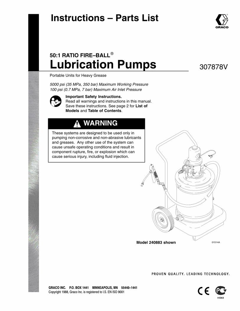
50:1 RATIO FIRE–BALL�
Lubrication PumpsPortable Units for Heavy Grease
5000 psi (35 MPa, 350 bar) Maximum Working Pressure100 psi (0.7 MPa, 7 bar) Maximum Air Inlet Pressure
307878V
WARNINGThese systems are designed to be used only inpumping non-corrosive and non-abrasive lubricantsand greases. Any other use of the system cancause unsafe operating conditions and result incomponent rupture, fire, or explosion which cancause serious injury, including fluid injection.
Model 240883 shown 01514A
Important Safety Instructions.Read all warnings and instructions in this manual.Save these instructions. See page 2 for List ofModels and Table of Contents.

2 307878
Table of ContentsList of Models 2. . . . . . . . . . . . . . . . . . . . . . . . . . . . . . . . . . . . . . . . . . . . . . . . . . . . . . . . . . . . . . . . . . . . . . . . . . . . . . . . . . . . Symbols 3. . . . . . . . . . . . . . . . . . . . . . . . . . . . . . . . . . . . . . . . . . . . . . . . . . . . . . . . . . . . . . . . . . . . . . . . . . . . . . . . . . . . . . . . Warnings 3. . . . . . . . . . . . . . . . . . . . . . . . . . . . . . . . . . . . . . . . . . . . . . . . . . . . . . . . . . . . . . . . . . . . . . . . . . . . . . . . . . . . . . . . Installation 5. . . . . . . . . . . . . . . . . . . . . . . . . . . . . . . . . . . . . . . . . . . . . . . . . . . . . . . . . . . . . . . . . . . . . . . . . . . . . . . . . . . . . . . Operation 12. . . . . . . . . . . . . . . . . . . . . . . . . . . . . . . . . . . . . . . . . . . . . . . . . . . . . . . . . . . . . . . . . . . . . . . . . . . . . . . . . . . . . Parts 13. . . . . . . . . . . . . . . . . . . . . . . . . . . . . . . . . . . . . . . . . . . . . . . . . . . . . . . . . . . . . . . . . . . . . . . . . . . . . . . . . . . . . . . . . Sound Data 18. . . . . . . . . . . . . . . . . . . . . . . . . . . . . . . . . . . . . . . . . . . . . . . . . . . . . . . . . . . . . . . . . . . . . . . . . . . . . . . . . . . . Graco Standard Warranty 20. . . . . . . . . . . . . . . . . . . . . . . . . . . . . . . . . . . . . . . . . . . . . . . . . . . . . . . . . . . . . . . . . . . . . . . Graco Information 20. . . . . . . . . . . . . . . . . . . . . . . . . . . . . . . . . . . . . . . . . . . . . . . . . . . . . . . . . . . . . . . . . . . . . . . . . . . . . .
List of ModelsModel No. Size Base Type * Dispense
KitCover Inductor Follow
PlatePail CE Installation
Kit 240831225006 120 lb portable X X X240880 � 120 lb portable X X X X225026 120 lb 2-wheel truck X X X245696 120 lb 2-wheel truck X X X240881 � 120 lb 2-wheel truck X X X X222245 120 lb 2-wheel truck X X X240882 � 120 lb 2-wheel truck X X X X225773 35 to 50 lb 2-wheel truck X X X245695 35 to 50 lb 2-wheel truck X X X240883 � 35 to 50 lb 2-wheel truck X X X X225827 35 to 50 lb – X X X240884 � 35 to 50 lb – X X X X222069 25 to 50 lb – X X X245694 25 to 50 lb – X X X240885 � 25 to 50 lb – X X X X226012 50 lb 2-wheel truck X X240886 � 50 lb 2-wheel truck X X X
� These models are CE certified.

3307878
SymbolsWarning Symbol
WARNINGThis symbol alerts you to the possibility of seriousinjury or death if you do not follow the instructions.
Caution Symbol
CAUTIONThis symbol alerts you to the possibility of damage toor destruction of equipment if you do not follow thecorresponding instructions.
Warnings
WARNINGSKIN INJECTION HAZARD
Spray from the gun, hose leaks, or ruptured components can inject fluid into your body and cause anextremely serious injury, including the need for amputation. Splashing fluid in the eyes or on the skincan also cause a serious injury.
� Fluid injected into the skin might look like just a cut, but it is a serious injury. Get immediatesurgical treatment.
� Do not point the dispensing valve at anyone or at any part of the body.
� Do not put hand or fingers over the valve.
� Do not stop or deflect fluid leaks with your hand, body, glove, or rag.
� Do not “blow back” fluid; this is not an air spray system.
� Always have the tip guard and the trigger guard on the dispensing valve when dispensing.
� Be sure the valve trigger safety operates before dispensing.
� Lock the valve trigger safety when you stop dispensing.
� Follow the Pressure Relief Procedure on page 12 whenever you are instructed to relievepressure; stop spraying; clean, check, or service the equipment; and install or clean the spray tip.
� Tighten all the fluid connections before operating the equipment.
� Check the hoses, tubes, and couplings daily. Replace worn, damaged, or loose parts immediately.Permanently coupled hoses cannot be repaired; replace the entire hose.
TOXIC FLUID HAZARD
Hazardous fluids or toxic fumes can cause a serious injury or death if splashed in the eyes or on theskin, swallowed, or inhaled.
� Know the specific hazards of the fluid you are using. Read the fluid manufacturer’s warnings.
� Store hazardous fluid in an approved container. Dispose of the hazardous fluid according to alllocal, state, and national guidelines.
� Wear appropriate protective clothing, gloves, eyewear, and respirator.
4 307878
WARNINGFIRE AND EXPLOSION HAZARD
Improper grounding, poor air ventilation, open flames, or sparks can cause a hazardous condition andresult in fire or explosion and serious injury.
� Ground the equipment and the object being dispensed. See Grounding on page 5.
� Provide fresh air ventilation to avoid the buildup of flammable fumes from solvent or the fluid beingdispensed.
� Extinguish all the open flames or pilot lights in the dispensing area.
� Electrically disconnect all the equipment in the dispensing area.
� Keep the dispensing area free of debris, including solvent, rags, and gasoline.
� Do not turn on or off any light switch in the dispensing area while operating or if fumes are present.
� Do not smoke in the dispensing area.
� Do not operate a gasoline engine in the dispensing area.
� If there is any static sparking while using the equipment, stop dispensing immediately. Identifyand correct the problem.
INSTRUCTIONS
EQUIPMENT MISUSE HAZARD
Equipment misuse can cause the equipment to rupture, malfunction, or start unexpectedly and resultin a serious injury.
� This equipment is for professional use only.
� Read all the instruction manuals, tags, and labels before operating the equipment.
� Use the equipment only for its intended purpose. If you are uncertain about usage, call your Gracodistributor.
� Do not alter or modify this equipment. Use only genuine Graco parts and accessories.
� Check the equipment daily. Repair or replace worn or damaged parts immediately.
� Do not exceed the maximum working pressure of the lowest rated system component. Thesepumps have a 5000 psi (35 MPa, 350 bar) maximum working pressure.
� Use fluids that are compatible with the equipment wetted parts. See the Technical Data section ofall the equipment manuals. Read the fluid manufacturer’s warnings.
� Route the hoses away from traffic areas, sharp edges, moving parts, and hot surfaces. Do notexpose Graco hoses to temperatures above 180�F (82�C) or below –40�F (–40�C).
� Do not use the hoses to pull equipment.
� Wear hearing protection when operating this equipment.
� Comply with all applicable local, state, and national fire, electrical, and other safety regulations.
5307878
InstallationGeneral Information
NOTE: Reference numbers and letters in parenthesesin the text refer to the callouts in the figures and theparts drawing.
NOTE: Always use genuine Graco parts andaccessories, available from your Graco distributor.
Air Line Accessories
See page 11 for recommended air accessories andinstallation.
Grounding
WARNINGFIRE AND EXPLOSION HAZARDBefore operating, ground the system asexplained below. Also read the sectionFIRE AND EXPLOSION HAZARD onpage 4.
To reduce the risk of static sparking, ground the pumpand all other components used or located in thedispensing area. Check your local electrical code fordetailed instructions for your area and type ofequipment.
Ground all of this equipment:
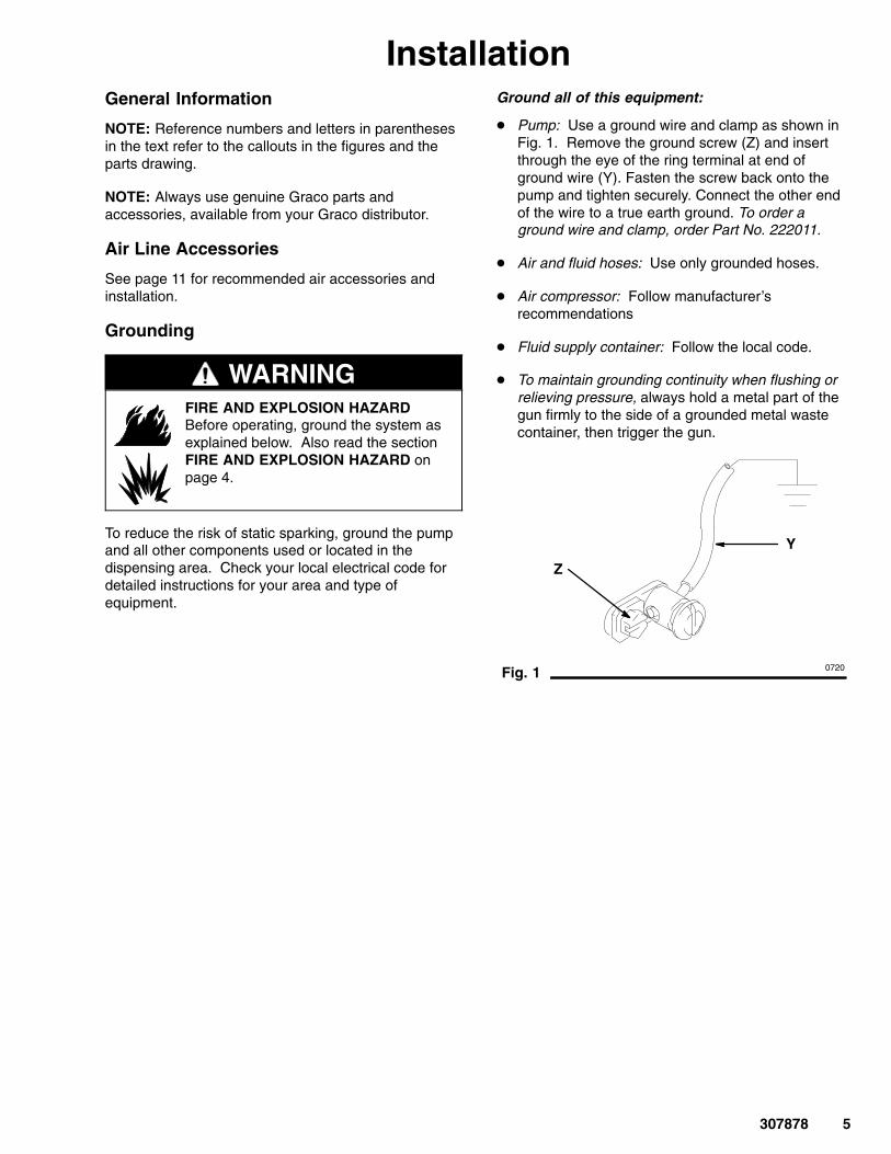
� Pump: Use a ground wire and clamp as shown inFig. 1. Remove the ground screw (Z) and insertthrough the eye of the ring terminal at end ofground wire (Y). Fasten the screw back onto thepump and tighten securely. Connect the other endof the wire to a true earth ground. To order aground wire and clamp, order Part No. 222011.
� Air and fluid hoses: Use only grounded hoses.
� Air compressor: Follow manufacturer’srecommendations
� Fluid supply container: Follow the local code.
� To maintain grounding continuity when flushing orrelieving pressure, always hold a metal part of thegun firmly to the side of a grounded metal wastecontainer, then trigger the gun.
Fig. 1
Y
0720
Z
6 307878
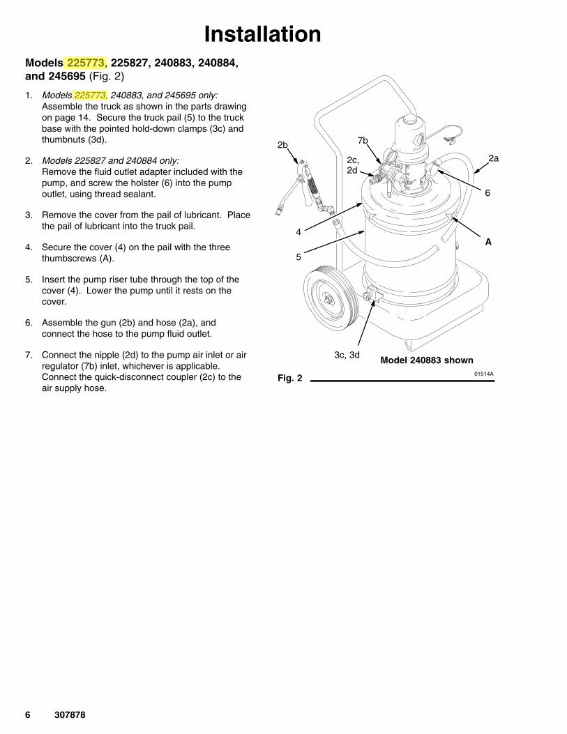
InstallationModels 225773, 225827, 240883, 240884,and 245695 (Fig. 2)
1. Models 225773, 240883, and 245695 only:Assemble the truck as shown in the parts drawingon page 14. Secure the truck pail (5) to the truckbase with the pointed hold-down clamps (3c) andthumbnuts (3d).
2. Models 225827 and 240884 only:Remove the fluid outlet adapter included with thepump, and screw the holster (6) into the pumpoutlet, using thread sealant.
3. Remove the cover from the pail of lubricant. Placethe pail of lubricant into the truck pail.
4. Secure the cover (4) on the pail with the threethumbscrews (A).
5. Insert the pump riser tube through the top of thecover (4). Lower the pump until it rests on thecover.
6. Assemble the gun (2b) and hose (2a), andconnect the hose to the pump fluid outlet.
7. Connect the nipple (2d) to the pump air inlet or airregulator (7b) inlet, whichever is applicable.Connect the quick-disconnect coupler (2c) to theair supply hose.
Fig. 2
2c,2d
4
5
3c, 3d
2b2a
A
7b
Model 240883 shown01514A
6

7307878
InstallationModels 225006, 225026,240880, 240881, and 245696 (Fig. 3)
1. For Models 225006 and 240880: Assemble thebase (3) as shown in the parts drawing onpage 15.
For Models 225026, 240881, 245696: Assemblethe truck (3) as shown in the parts drawing onpage 14.
2. Remove the fluid outlet adapter included with thepump, and screw the holster (6) into the pumpoutlet, using thread sealant.
3. Place an open 120-lb drum of grease on mountingbase or truck and secure it with the hold-downclamps.
For portable base models, 225006 and 240880:For steel drums use pointed end of (3c). Positionclamps above drum bead. Tighten bolts (3b). Forfiber drums reverse (3c) to use flat–end.
For truck model, 225026, 245696 and 240881: Forsteel drums use pointed–end of (3c). Positionclamp above drum bead. Tighten thumbnuts (3d).
4. Press the follow plate (5) down firmly onto thegrease, and rotate it to eliminate air pockets andreduce channeling. Insert the pump through thecover (4). Slide the cover up far enough to let thepump pass easily through the follow plategrommet.
5. Secure the cover on the drum with thethumbscrews (A). It is not necessary to bolt thepump to the cover.
6. Assemble the gun (2b) and hose (2a), and connectthe hose to the pump fluid outlet.
7. Connect the nipple (2d) to the pump air inlet or airregulator (7b) inlet, whichever is applicable.Connect the quick-disconnect coupler (2c) to theair supply hose.
Fig. 3
2c, 2d
45
6
2a
3
3b, 3c
Model 240881 shown
7b
01516A
A
2b
3c, 3d

8 307878
InstallationModels 222069, 240885, and 245694 (Fig. 4)
1. Remove the cover from the pail, and scoop thelubricant from the center to the sides of the pail tomake its surface concave.
2. Center the follow plate (5) in the pail opening.Press the plate firmly downward and rotate it overthe lubricant surface to eliminate air pockets andprevent channeling.
3. Place the cover (3a) on the pail, and tighten thethumbscrews (3f).
4. Assemble the gun (2b) and hose (2a), and connectthe hose to the pump fluid outlet.
5. Connect the nipple (2d) to the pump air inlet or airregulator (7b) inlet, whichever is applicable.Connect the quick-disconnect coupler (2c) to theair supply hose.
Fig. 4
2a
2c, 2d
3f3a
7b
Model 240885 shown
01517A
2b
5

9307878
InstallationModels 222245 and 240882 (Fig. 5)
1. Assemble the cart (6) as shown at right. Use only2 of the 4 brackets (5d) supplied. Install the rearpositions of the drum shelf (6b) as shown.
2. Place an open 120-lb drum of grease on the drumshelf.
3. Press the follow plate (4) down firmly onto thegrease, and rotate it to eliminate any air pocketsand reduce channeling. Insert the pump throughthe cover (3). Slide the cover up far enough toallow the pump to pass easily through the followplate grommet and into the grease.
4. Using items 3a to 5d, secure the cover to thedrum, and the drum to the cart. It is not necessaryto bolt the pump to the cover.
5. Assemble the gun (2b) and hose (3a), and connectthe hose to the pump fluid outlet.
6. Connect the quick-disconnect nipple (2d) to thepump air inlet or air regulator (7b) inlet, whicheveris applicable. Connect the quick-disconnectcoupler (2c) to the air supply hose.
Fig. 5
2b
2c2d
3
6
4
6b
5a
5b
5c
5d
Model 240882 shown
01518A
2a
7b

10 307878
InstallationModels 226012 and 240886 (Fig. 6)
1. Assemble the truck as shown in the Parts Drawingon page 14 but do not assemble the handle.
2. Slide handle through elevator slide tube andsecure handle to base.
3. Remove the fluid outlet adapter included with thepump, and screw the holster (6) into the pumpoutlet, using thread sealant.
4. Secure pump to elevator mounting plate.
5. Remove inductor plate locking nut, locking ring,and o–ring (Fig. 7).
6. In order, slide inductor plate locking nut, lockingring, and o–ring on pump riser tube.
7. Adjust the inductor plate on the pump riser tubeso the slots are showing just below the inside ofthe plate (Fig. 7). TIghten the locking nut securely
8. Open the inductor plate vent by turning the knobcounterclockwise.
9. Place an open 50-lb pail of grease on the truck,and secure it with the hold-down clamps.
10. Remove the cover from the pail, and scoop thelubricant from the center to the sides of the pail tomake its surface concave.
11. Center the inductor plate (5) in the pail opening.Press down on the pump and rock it back andforth to seat the inductor plate to eliminate airpockets. Continue action until material appears atthe vent opening.
12. Close the inductor plate vent by turning the knobclockwise.
13. Assemble the gun (2b), Z–swivel, and hose (2a).Connect hose (2a) to holster (6) or to pump fluidoutlet adapter if you chose not to use the holster.
14. Connect the nipple (2d) to the pump air inlet or airregulator (7b) inlet, whichever is applicable.Connect the quick-disconnect coupler (2c) to theair supply hose.
Fig. 6
6
3c, 3d
5
2a
2b 2c, 2d7b
Model 240886 shown
7462B
Fig. 7
Locking nut
Locking ring
5
06383
1/8” (3 mm)Pump intake slots
Pump riser tube

11307878
InstallationThe installation shown below is only a guide for selecting and installing system components and accessories.Contact your Graco distributor for assistance in designing a system to suit your particular needs.
Typical Installation
Key
ABCDEFGHJK
Fluid dispense linePump ground wire (required)Air regulatorMain air supply lineAir filterPump lubricatorPump runaway valveBleed-type master air valve (required)Quick-disconnect couple and nippleAir regulator (7b) with safety valve (7c) and gauge (not shown)Included with Models 240880 to 240886 A
B
E C F GH
J
D
01519A
Air Line and Accessories
NOTE: Install air line accessories in the order shown inthe Typical Installation.
� Install a pump runaway valve (G) to shut off the airtp the pump if the pump accelerates beyond thepreadjusted setting. A pump that runs too fast canbe seriously damaged.
� Install an air line lubricator (F) for automatic airmotor lubrication.
� Install a bleed-type master air valve (H) to relieveair trapped between the valve and the motor whenthe valve is closed.
WARNINGTrapped air can cause the air motor to cycle unex-pectedly, causing serious injury if you are adjustingor repairing the pump. Be sure to follow the Pres-sure Relief Procedure on page 12.
� Install the air regulator (C) to control pump speedand pressure.
� On the main air supply line from the compressor,install an air line filter (E) to remove harmful dirt andcontaminants from the compressed air supply.
� For Models 240880 through 240886, install theprovided air regulator/safety valve (K) at the pumpair inlet with the nipple (7a, also included).
CAUTIONAvoid hanging air accessories directly on the pumpair inlet. The fittings are not strong enough to sup-port the accessories and may cause one or more tobreak. If accessories must be installed directly onthe pump, provide a bracket on which to mountthem.

12 307878
OperationPressure Relief Procedure
WARNINGINJECTION HAZARDFluid under high pressure can be in-jected through the skin and cause serious injury. To reduce the risk of an
injury from injection, splashing fluid, or movingparts, follow the Pressure Relief Procedurewhenever you
� Are instructed to relieve the pressure� Stop dispensing� Check or service any of the system equipment� Install or clean the fluid nozzles
1. Shut off the air to the pump.
2. Bleed off the air pressure by closing the airregulator (self-relieving type), or closing thebleed-type master air valve installed upstream ofthe air regulator, or disconnecting the air supplyhose at the quick-disconnect.
3. Hold a metal part of the gun or valve firmly to theside of a grounded metal waster container andtrigger to relieve fluid pressure.
Start-up: Single or Multiple Pump Systems
1. Close the air regulators and bleed-type master airvalves to all but one pump.
2. Open the master air valve from the compressor.
3. For the pump which is connected, trigger thedispensing valve into a grounded metal wastecontainer, making firm metal-to-metal contactbetween the container and valve. Open thebleed-type master air valve, and open the pump airregulator slowly until the pump is running. Whenthe pump is primed and all air has been pushedout of the lines, release the trigger.
4. If you have more than one pump, repeat thisprocedure for each pump.
NOTE: When the pump is primed, and with sufficientair supplied, the pump starts when the dispensingvalve is opened and shuts off when it is closed.
5. Set the air pressure to each pump at the lowestpressure needed to get the desired results.
NOTE: A pump runaway valve can be installed onthe air line to automatically shut off the pump if itstarts to run too fast.
Never allow the pump to run dry of the fluid beingpumped. A dry pump will quickly accelerate to ahigh speed, possibly damaging itself. If the pumpaccelerates quickly or is running too fast, stop itimmediately and check the fluid supply. If thesupply container is empty and air has beenpumped into the lines, prime the pump and lineswith fluid, or flush it and leave it filled with acompatible solvent. Be sure to eliminate all airfrom the fluid system.
WARNINGThe maximum working pressure of each pump inyour system may not be the same. To reduce therisk of over-pressurizing any part of your system,be sure you know the maximum working pressurerating of each pump and its connected compo-nents. Never exceed the maximum working pres-sure of the lowest rated component connected to aparticular pump.
To determine the fluid output pressure using the airregulator reading, multiply the ratio of the pump bythe air pressure shown on the regulator gauge. Forexample:
50:(1) ratio x 100 psi air = 5000 psi fluid output
50:(1) ratio x 0.7 MPa air = 35 MPa fluid output
50:(1) ratio x 7 bar air = 350 bar fluid output
Limit the air to the pump so that no air line or fluidline component or accessory is overpressurized.
6. Read and follow the instructions supplied witheach component in the system.
7. When shutting off the system, always follow thePressure Relief Procedure at left.

13307878
PartsRef. No. 2, Dispense Kit 222070
RefNo. Part No. Description Qty.
2a 109151 HOSE, 1/4 npt(mbe); 12 ft (3.7 m) 12b 242056 VALVE 12c 114558 COUPLER, quick-disconnect 12d 169971 NIPPLE, quick-disconnect 12e 202577 Z-SWIVEL 1
Model 225827, 35- to 50-lb pail sizeIncludes items 1 to 6Model 240884, 35- to 50-lb pail sizeIncludes items 1 to 7RefNo. Part No. Description Qty.1 239877 PUMP, 50:1 Fire-Ball;
See manual 308883 for parts 12 222070 DISPENSE KIT;
See parts list above 13 204134 PAIL 14 204574 COVER;
see manual 306345 for parts 16 203976 HOLSTER 17 240831 CE INSTALLATION Kit
See part list on page 17 1
Model 222069 and 245694,25- to 50-lb pail sizeIncludes items 1 to 5Model 240885, 25- to 50-lb pail sizeIncludes items 1 to 7RefNo. Part No. Description Qty.1 239877 PUMP, 50:1 FIre-Ball;
See manual 308883 for parts 12 222070 DISPENSE KIT;
See parts above 1245697 DISPENSE KIT; (245694 only)
See parts list on page 15 13 222059 COVER; includes items 3a to 3h 13a 207617 . COVER, pail 13b 168102 . PLATE, stop, pump 13c 158048 . BUMPER, button, rubber 13d 159608 . RIVET 13e 150868 . HOLDER, gun 13f 100220 . SCREW, thumb 33g 100025 . NUT, 1/4 npsm thd 13h 100579 . PIN, cotter; 1/8” x 1” 15 220653 FOLLOW PLATE;
See manual 306345 for parts 17 240831 CE INSTALLATION Kit
See part list on page 17 1
1
6
1
4
3
2c2d
2a01520
2e
2b
5
3f
2
3b
3c
3h
3e
7
7
Model 240884 shown
Model 240885 shown
01521A
2
01517A
3d
3a
3g
14 307878
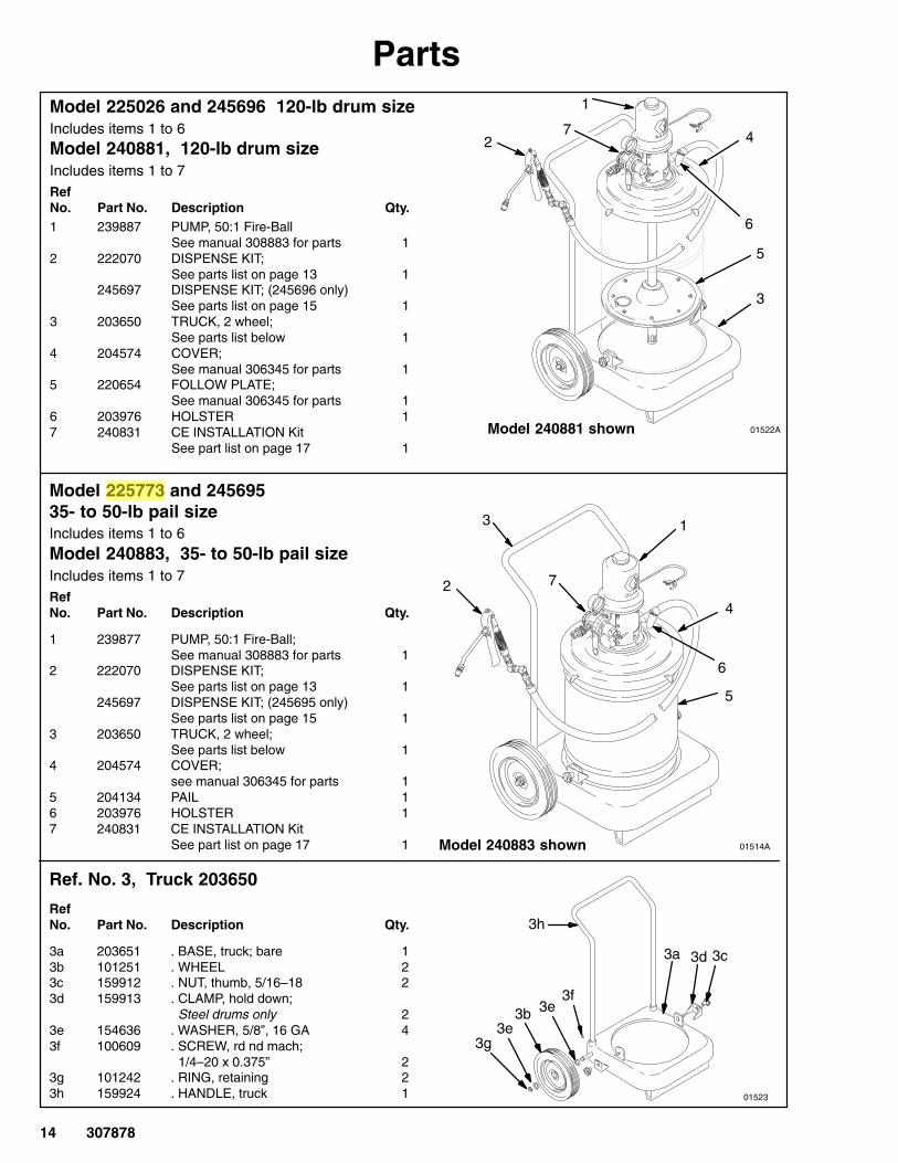
PartsModel 225026 and 245696 120-lb drum sizeIncludes items 1 to 6Model 240881, 120-lb drum sizeIncludes items 1 to 7RefNo. Part No. Description Qty.1 239887 PUMP, 50:1 Fire-Ball
See manual 308883 for parts 12 222070 DISPENSE KIT;
See parts list on page 13 1245697 DISPENSE KIT; (245696 only)
See parts list on page 15 13 203650 TRUCK, 2 wheel;
See parts list below 14 204574 COVER;
See manual 306345 for parts 15 220654 FOLLOW PLATE;
See manual 306345 for parts 16 203976 HOLSTER 17 240831 CE INSTALLATION Kit
See part list on page 17 1
Model 225773 and 245695 35- to 50-lb pail sizeIncludes items 1 to 6Model 240883, 35- to 50-lb pail sizeIncludes items 1 to 7RefNo. Part No. Description Qty.
1 239877 PUMP, 50:1 Fire-Ball;See manual 308883 for parts 1
2 222070 DISPENSE KIT;See parts list on page 13 1
245697 DISPENSE KIT; (245695 only)See parts list on page 15 1
3 203650 TRUCK, 2 wheel;See parts list below 1
4 204574 COVER;see manual 306345 for parts 1
5 204134 PAIL 16 203976 HOLSTER 17 240831 CE INSTALLATION Kit
See part list on page 17 1
Ref. No. 3, Truck 203650
RefNo. Part No. Description Qty.
3a 203651 . BASE, truck; bare 13b 101251 . WHEEL 23c 159912 . NUT, thumb, 5/16–18 23d 159913 . CLAMP, hold down;
Steel drums only 23e 154636 . WASHER, 5/8”, 16 GA 43f 100609 . SCREW, rd nd mach;
1/4–20 x 0.375” 23g 101242 . RING, retaining 23h 159924 . HANDLE, truck 1
42
3
3h
3g3e
3b3f
3e
3c
1
6
4
5
3d3a
01523
7
7
Model 240881 shown
Model 240883 shown
01522A
5
6
1
01514A
2
3

15307878
Parts
Model 225006, 120-lb drum sizeIncludes items 1 to 6Model 240880, 120-lb drum sizeIncludes items 1 to 7
RefNo. Part No. Description Qty.
1 239887 PUMP, 50:1 Fire-BallSee manual 308883 for parts 1
2 222070 DISPENSE KITSee parts list on page 13 1
3 203622 PORTABLE BASESee parts list below 1
4 204574 COVERSee manual 306345 for parts 1
5 220654 FOLLOW PLATESee manual 306345 for parts 1
6 203976 HOLSTER 17 240831 CE INSTALLATION Kit
See part list on page 17 1
Ref. No. 3, Portable Base 203622, Series B
RefNo. Part No. Description Qty.
3a 191750 BASE, drum 13b 102547 BOLT, hex hd; 5/16”–18 x 1.5” 23c 191747 BRACKET 23d 100214 WASHER, lock 23e 100132 WASHER, flat 23f 113660 RIVET 163g 113646 CASTER; polyurethane 4
3a
06472A
3b
3c3e
3d
3f
3g
2
Model 240880 shown
1
Ref. No. 2, Dispense Kit 245697
RefNo. Part No. Description Qty.
2a 109151 HOSE, 1/4 npt(mbe); 12 ft (3.7 m) 12b 233807 VALVE 12c 114558 COUPLER, quick-disconnect 12d 169971 NIPPLE, quick-disconnect 12e 202577 Z-SWIVEL 1
2d
2c2d
2a
2e
2b
01520
1
7
4
6
5
3

16 307878
Parts
Ref. No. 2, Dispense Kit 222383
RefNo. Part No. Description Qty.
2a 109154 HOSE 12b 242056 VALVE 12c 114558 COUPLER, quick-disconnect 12d 169971 NIPPLE, quick-disconnect 12e 202577 Z-SWIVEL 1
Model 222245, 120-lb drum sizeIncludes items 1 to 6
Model 240882, 120-lb drum sizeIncludes items 1 to 7
RefNo. Part No. Description Qty.
1 239887 PUMP, 50:1 Fire-Ball;See manual 308883 for parts 1
2 222383 DISPENSE KIT;See parts list above 1
3 222060 COVER; See manual 306345 for parts 1
4 220654 FOLLOW PLATE;See manual 306345 for parts 1
5 222061 HOLD DOWN KIT;Includes items 5a to 5d
5a 200889 . NUT, wing 25b 153166 . HOOK, drum mounting 25c 153102 . ROD, drum 25d 159016 . BRACKET, retaining (2 used) 46 222243 CART KIT; includes items 6a to 6n 16a 218027 . FRAME, cart 26b 183987 . SHELF, drum 16c 107144 . SCREW, cap; 3/8–16 x 2–1/4 46d 179766 . HANDLE, cart 16e 100731 . WASHER, flat; 3/8 66f 101566 . LOCKNUT, hex; 3/8/16 66g 179770 . AXLE 16h 154628 . WASHER, flat; 3/4 46j 107146 . RING, retaining, ext; 3/4 46k 106039 . WHEEL, tire, pneumatic 26m 107145 . CAP, tube 26n 100680 . CAPSCREW; 3/8–16 x 7/8 26p 159016 . BRACKET, retaining 27 240831 CE INSTALLATION Kit
See part list on page 17 1
2c2d
2a01520
2e
2b
2
3
6g
4
6b
5a5b5c
5d
6c
6e
6d
6m
6f
6j
6a6h
6n
6p 6e 6f 6k 6h 6j
1
Model 240882 shown01518A
7

17307878
Parts
Model 226012, 50-lb pail sizeIncludes items 1 to 6
Model 240886, 50-lb pail sizeIncludes items 1 to 7
RefNo. Part No. Description Qty.
1 239877 PUMP, 50:1 Fire-BallSee manual 308883 for parts 1
2 222070 DISPENSE KIT;See parts list on page 13 1
3 203650 TRUCK, portable;See parts list on page 14 1
4 203664 ELEVATOR 15 204351 FOLLOW PLATE 16 203976 HOLSTER 17 240831 CE INSTALLATION Kit
See part list on page 17 1
13
4
5
6
Ref. No. 7, CE Installation Kit 240831
RefNo. Part No. Description Qty.
7a 156849 NIPPLE 17b 109075 REGULATOR, air, with gauge 17c 103347 VALVE, safety 17d 222011 CLAMP, grounding 17e � CE Label 1
� Attention: To comply with CE directives, theCE identification label must be affixed to the backof the cart or to the top of the drum cover.Permanently mark the date of assembly on thelabel.
7
Model 240886 shown7462B
2
8418A
7a
7b
7d
7e
7c

18 307878
Sound DataSee the pump instruction manual for technical data including wetted parts, port sizes, maximum air consumption,maximum delivery, and so on. Sound data for the air motors of the pumps on these portable units is as follows:
Tested at 100 psi (0.7 MPa, 7 bar) at 40 cycles per minute
Sound Pressure Level, measured at 1 meter from unit 77.9 dB(A)
Sound Power Level, tested in accordance with ISO 9614–2 85.6 dB(A)

19307878
Notes

20 307878
Graco Standard WarrantyGraco warrants all equipment manufactured by Graco and bearing its name to be free from defects in material and workmanship on thedate of sale to the original purchaser for use. With the exception of any special, extended, or limited warranty published by Graco,Graco will, for a period of twelve months from the date of sale, repair or replace any part of the equipment determined by Graco to bedefective. This warranty applies only when the equipment is installed, operated and maintained in accordance with Graco’s writtenrecommendations.
This warranty does not cover, and Graco shall not be liable for general wear and tear, or any malfunction, damage or wear caused byfaulty installation, misapplication, abrasion, corrosion, inadequate or improper maintenance, negligence, accident, tampering, orsubstitution of non-Graco component parts. Nor shall Graco be liable for malfunction, damage or wear caused by the incompatibility ofGraco equipment with structures, accessories, equipment or materials not supplied by Graco, or the improper design, manufacture,installation, operation or maintenance of structures, accessories, equipment or materials not supplied by Graco.
This warranty is conditioned upon the prepaid return of the equipment claimed to be defective to an authorized Graco distributor forverification of the claimed defect. If the claimed defect is verified, Graco will repair or replace free of charge any defective parts. Theequipment will be returned to the original purchaser transportation prepaid. If inspection of the equipment does not disclose any defectin material or workmanship, repairs will be made at a reasonable charge, which charges may include the costs of parts, labor, andtransportation.
THIS WARRANTY IS EXCLUSIVE, AND IS IN LIEU OF ANY OTHER WARRANTIES, EXPRESS OR IMPLIED, INCLUDING BUTNOT LIMITED TO WARRANTY OF MERCHANTABILITY OR WARRANTY OF FITNESS FOR A PARTICULAR PURPOSE.
Graco’s sole obligation and buyer’s sole remedy for any breach of warranty shall be as set forth above. The buyer agrees that no otherremedy (including, but not limited to, incidental or consequential damages for lost profits, lost sales, injury to person or property, or anyother incidental or consequential loss) shall be available. Any action for breach of warranty must be brought within two (2) years of thedate of sale.
Graco makes no warranty, and disclaims all implied warranties of merchantability and fitness for a particular purpose in connectionwith accessories, equipment, materials or components sold but not manufactured by Graco. These items sold, but not manufacturedby Graco (such as electric motors, switches, hose, etc.), are subject to the warranty, if any, of their manufacturer. Graco will providepurchaser with reasonable assistance in making any claim for breach of these warranties.
In no event will Graco be liable for indirect, incidental, special or consequential damages resulting from Graco supplying equipmenthereunder, or the furnishing, performance, or use of any products or other goods sold hereto, whether due to a breach of contract,breach of warranty, the negligence of Graco, or otherwise.
FOR GRACO CANADA CUSTOMERSThe parties acknowledge that they have required that the present document, as well as all documents, notices and legal proceedingsentered into, given or instituted pursuant hereto or relating directly or indirectly hereto, be drawn up in English. Les partiesreconnaissent avoir convenu que la rédaction du présente document sera en Anglais, ainsi que tous documents, avis et procéduresjudiciaires exécutés, donnés ou intentés à la suite de ou en rapport, directement ou indirectement, avec les procedures concernées.
Graco InformationTO PLACE AN ORDER, contact your Graco distributor, or call this number to identify the distributor closest to you:
1–800–533–9655 Toll Free612–623–6928
612–378–3590 Fax
All written and visual data contained in this document reflects the latest product information available at the time of publication.Graco reserves the right to make changes at any time without notice.
This manual contains English. MM 307878
Graco Headquarters: MinneapolisInternational Offices: Belgium, Korea, China, Japan
www.graco.com 02/1988, Revised 08/2007