307 pump users guide
TRANSCRIPT

307 Piston PumpUser’s Guide


307 Piston PumpUser’s Guide
LT801171J/©2001 Gilson SAS All rights reserved February 2001


1 1
MODEL 307 PISTON PUMP
CONTENTS
1 INTRODUCTION 3Using this manual 3Unpacking 3Warranty 3Customer Service 3
DESCRIPTION 4Front view 4Keypad 5Rear view 6
INSTALLATION 7Electrical installation 7Mechanical installation 8Positioning the modules 9Control connections 9Hydraulic connections 9Input/Output connections 9
OPERATION 12Switching on the pump 12Setting up the pump 13Using the Flow mode 19Using the Dispense mode 20Using the Program mode 21Programming the error files 26Running a method program 28Programming example 30
MAINTENANCE 32
TROUBLESHOOTING 33Electrical problems 33Hydraulic problems 33
APPENDICES 34A. Accessory parts list 34B. GSIOC control 35C. Solvent miscibility table 36D. Liquid compressibility values 37E. Flowrate accuracy principle 38F. 307 Programming chart 39G. 307 Programming sheet 40H. Technical Data 42
INDEX 44
5
2
4
6
3
7

2 2
MODEL 307 PISTON PUMP
SAFETY
Please read this section carefully before installing and operating the equipment.
The instrument described in this User’s Guide is a programmable piston pump that can give flow rate gradientsand can synchronize with other instruments using rear panel input and output connections. It should only beused in the laboratory or similar indoor environment, by qualified personnel. If the instrument is used in amanner not specified by Gilson, the protection provided by the instrument may be impaired.
For safe and correct use of the instrument, it is essential that both operating and service personnel followgenerally accepted safety procedures as well as the safety instructions given in this User’s Guide.
Cleaning, installation, dismantling, maintenance, adjustment and repair should only be performed bypersonnel trained in such work, and who are aware of the possible dangers involved.
Voltages present inside the instrument are potentially dangerous. If there is a problem with the instrument, thepower cable should be removed until qualified service personnel have repaired it. This is to prevent anyone frominadvertently using the instrument, thus causing possible harm to themselves or damage to the instrumentitself.
The leakage current of this instrument is within the limits allowed by safety standards for laboratory equipment.An efficient ground connection is imperative for the physical protection of the user.
Ensure that the ventilation fan on the Piston Pump operates and is not obstructed when the instrument isinstalled.
Power supply cord reference 500005 is for use in France and Germany. Power supply cord reference 500006is for use in the USA and Canada. For other countries contact your local Gilson representative. You must onlyuse the type of fuse described and specified in this document: 2.0 Amp type “T” slow blow for use where thepower supply is between 100 V and 120 V, 1.0 Amp type “T” slow blow for use where the power supply isbetween 220 V and 240 V.
Adequate protection such as ventilation must be provided if dangerous liquids are used in the analytical work.If incidental spillage occurs, carefully clean-up the spillage, taking into account the nature of the spilled liquidincluding all required safety measures.
This instrument must not be sterilized, using an autoclave, or any other mechanical device. When you needto clean this instrument, use one of the three following methods:
1 - A clean dry cloth.2 - A cloth dampened with water.3 - A cloth dampened with soapy water.
If a cloth dampened with soapy water is used to clean the instrument, only domestic soap may be used. No otherform of detergent or chemical may be used.
Safety Symbols
The following electronic and hazard symbols appear on the307 Module:
Symbol Explanation
Alternating current
PROTECTIVE CONDUCTOR TERMINAL
On (Supply switch)
Off (Supply switch)
Caution, risk of electric shock
Caution (refer to accompanying documents)!
I
O
~

3 3
MODEL 307 PISTON PUMP
INTRODUCTION 1
The Gilson 307 Piston Pump is designed to produce accurate and reproducible flow rates in the range0.025 to 5 ml/min. It can be programmed to give flow rate gradients and to synchronize with otherinstruments using the inputs and outputs.
USING THIS MANUAL
The 307 Piston Pump is a precision instrument which is simple and easy to use. To gain themaximum from the instrument, you should:
• Read the description of the instrument in chapter 2.• Install the instrument as shown in chapter 3.• Follow the operating instructions given in chapter 4.
UNPACKING
The 307 Piston Pump is packed in a single carton. Upon receipt of your instrument, carefullyunpack the unit and inspect it for possible damage. Check the contents of the carton againstthe parts list to verify that all parts are included and undamaged. The parts list is given inAppendix A. Do this now, even if the unit will not be used immediately. Report any damageto the responsible carrier immediately. Read the description in chapter 2 to become familiarwith the instrument, its different parts and their names.
WARRANTY
If the instrument does not appear to function correctly, first verify the electrical connectionsare correct and that the instrument is switched ON. Contact your Gilson agent for technicaladvice or an eventual service visit. Any service required will be given within the warrantyconditions assured by your Gilson agent.
CUSTOMER SERVICE
Gilson and its worlwide network of authorized representatives provide you with four typesof assistance: sales, technical, applications and service.
The service personnel of Gilson's representatives are able to serve you more efficiently if youprovide the following information:
• The serial number and model number of the equipment involved.• Computer model (if used), available memory, microprocessor and operating software
version(s) in operation.• The installation procedure you used.• A concise list of the symptoms.• A list of operating procedures and conditions you were using when the problem arose.• A list of other devices connected to the system and a system diagram showing the connections.• A list of other electrical connections in the room.
1
2
3
4

4 4
MODEL 307 PISTON PUMP
2DESCRIPTION
This chapter describes the physical layout of the 307 pump. It describes the front panel of the pump andthe position of the electrical connectors on the rear panel.
FRONT VIEW
Figure 1 shows a front view of the 307 pump with a pump head mounted. There is a keypadwhich consists of a display, a numeric keypad and soft keys for programming the 307. Thepump head is mounted on the right hand side.
1
Figure 1
1 - Digital display2 - Numeric keypad3 - Pump head4 - Pump head clamp5 - Pump head inlet6 - Pump head outlet7 - Manometric module connections8 - Side grip9 - Side screws

5 5
MODEL 307 PISTON PUMP
DESCRIPTION 2
KEYPAD
Figure 2 shows the keypad with the numeric keys, the display and the soft keys.
1) Power on indicator
2) Display: two 24-character lines are used to displayparameters, commands and messages.
3) Softkeys: their functions are determined by thesoftware and may change from menu to menu. Thepresent functions are displayed above each softkey.
4) PRIME: the pump runs at its maximum flowrate untilyou press the STOP softkey.
5) HELP: displays advice and instructions at any time, withno effect on the operation of the pump.
6) CANCEL: cancels your last entry before it has beenstored in the memory.
7) ENTER: confirms a selection or parameter value andstores t in the memory.
8) Numeric keypad: this is used to key in values duringprogramming. The parameter being modified is alwaysunderlined with a flashing cursor.
2
Figure 2

6 6
MODEL 307 PISTON PUMP
DESCRIPTION 2
REAR VIEW
Figure 3 shows a rear view of the 307 Piston Pump with the electrical connectors. The functionof each connector is as follows:
• GSIOC FROM CONTROLLER Connection to a computer.• INPUT/OUTPUT CONTROLS Connector for the 307 inputs and outputs.• Power switch On/off power switch.• Power receptacle Voltage selector and fuse holder.
3
Figure 3 - Rear view
1 - Power switch2 - Power socket3 - Fuse holder and voltage selector4 - Input/Output socket5 - GSIOC from controller socket6 - Manometric module

7 7
MODEL 307 PISTON PUMP
INSTALLATION 3
This chapter describes how to install the 307 pump. It is recommended that you follow the installationinstructions in the order that they are presented in the manual.
ELECTRICAL INSTALLATION
The instrument requires two fuses to be installed. The type of fuses required are:2.0 Amp type “T” slow blow for 100 - 120 V, 1.0 Amp type “T” slow blow for 220 - 240 V.
For safety reasons, Piston Pumps are delivered without fuses installed. Fuses must be installedby the user upon delivery.
INSERTING THE FUSES
Ensure that the power cord is not connected before startingto install the fuses. Follow the procedure below to install thetwo fuses.
• The voltage selector and fuse holder is located below thepower socket. See Figure 4. Pull the voltage selector out ofthe power receptacle. This is done by gently levering theselector out using a small screwdriver.
• Pull out the drawer as shown in Figure 4. Insert the firstfuse into the clips.
• Push the drawer back into position.
• Pull out the drawer for the second fuse which is on theother side of the voltage selector. Insert the second fuse intothe clips.
The following fuse ratings are used, depending on the volt-age selected. The two fuses are included in the standardaccessory package.
SELECTING THE VOLTAGE
The 307 Piston Pump can be set to operate at 100/120 volts or 220/240 volts. The differentvoltages are selected depending on the orientation of the fuse holder.
• To set the voltage to 100/20 volts: Insert the fuse holder with the numbers 110/120 on thebottom, facing the small white arrow.
• To set the voltage to 220/240 volts: Insert the fuse holder with the numbers 220/240 on thebottom, facing the small white arrow.
For safety reasons, do not connect the power cord until you have finished assemblingthe instrument.
1
1.1Voltage selection Fuse value
(V) (A)
100-120 2.0220-240 1.0
Figure 4
1.2
!

8 8
MODEL 307 PISTON PUMP
3INSTALLATION
2 MECHANICAL INSTALLATION
This section explains how to install the pump head, the mast clamp and mast. The pump headand mast clamp for each pump should be installed before positioning the modules.
PUMP HEAD INSTALLATION
The pump head is shipped in a hard case to protect it during transit. Unpack the pump headfrom its case and check that all of the parts are included. Follow the procedure below toinstall the pump head.
• Insert the pump head into the front apertureof the pump. See Figure 5. The notch at thebottom of the pump head body must be fittedon to the matching pin on the pump, justbelow the aperture. This notch ensures thatthe inlet port is on the bottom and the outletport is on the top.
• Holding the pump head in place with onehand, set the clamp diagonally over the head.
• Turn the clamp clockwise into position inthe slots on both sides of the pump head.
• Tighten the thumb screw until the clampholds the pump head securely. Make surethat the clamp ends are secured in theirslots on both sides.
See the pump head User’s Guide for more information.
MAST INSTALLATION
The mast is used to stabilise a system when severalmodules are stacked on top of each other. It is usedto hold the prime/purge valve and a manualinjection valve. The mast clamp should be installedbefore positioning the 307 pump in a system. Themast is added after all of the modules have been putin place. Follow the procedure below to install themast clamp.
• Remove the side screw holding the modulecover. See Figure 6.
• Screw on the mast clamp.
Fix one clamp onto each module in the system. Afterall the modules have been positioned, the stainlesssteel mast can be secured within the clamps.
2.1
Figure 5
2.2
Figure 6

9 9
MODEL 307 PISTON PUMP
INSTALLATION 3
3 POSITIONING THE MODULES
Before putting each module in position, make sure that eachmodule is ready, i.e. that the fuses have been installed andthat any mechanical installation is finished.
The physical positioning of each of the modules in yoursystem will depend on your type of system. A suggestedlayout is given below for a 307 pump and a Gilson 231-401auto-sampler. This is an auto-analytical system with 1 pump,1 detector and 1 auto-sampler. The 307 should be on top. Thismakes it easy to read the display and to use the keypad.
CONTROL CONNECTIONS
The 307 pump and the other modules in a Gilson system communicate using the Gilson SerialInput/Output Channel (GSIOC). Each module in a system has a GSIOC connector on its rearpanel and is connected to a system controller using a GSIOC cable. This is the case when a 307pump is controlled by a computer with a Gilson HPLC software package.
• To connect the 307 pump to a system controller:Connect the socket marked GSIOC FROM CONTROLLER on the rear panel of the 307 pumpto the system controller using a GSIOC cable.
HYDRAULIC CONNECTIONS
The hydraulic connections for the 307 pump head are made using the tubing provided in thestandard accessory package. Connect the 307 pump head input with the inlet tubing assemblyprovided with the pump head. The connections to the 307 pump head output should be madeusing stainless steel tubing. The outlet of the pump head should be connected to one of the twoports of the internal dampener/transducer. The other port is then connected to the rest of the system.
INPUT/OUTPUT CONNECTIONS
For coordination with surrounding equipment, electrical contactsare used.
The Input/Output connector is a 14-pin terminal block connector.Connections are made to the inputs and outputs using the connectorsupplied in the standard accessory package.
4
Figure 7
307
231
Det.
401
5
6
Inputs Outputs
Start/Stop Out# 1Pause/Resume Out# 2
IN #1 Out# 3IN #2 Out# 4

10 10
MODEL 307 PISTON PUMP
INSTALLATION 3
6.1 Pin # Function
1 Ground2 Start / Stop Input3 Pause/Resume Input4 IN # 1 Input5 IN # 2 Input6 Out # 3 Output7 Out # 3 Output8 Out # 2 Output9 Out # 2 Output
10 Out # 1 Output11 Out # 1 Output12 Out # 4 Common13 Out # 4 Normally closed14 Out # 4 Normally open
Start/Stop Input
Pause/Resume
Wait for Input # 1
Activate Input # 2
Output 1Output 2Output 3
Inputs to Output contacts the 307 from the 307
307 I/O Connector
Contacts fromother equipment
Output 4
Figure 8
Mode Input Result
Flow Closed Start flowOpen Stop flow
Dispense Closed Start DispenseOpen Stop Dispense
Program Closed Start programOpen Stop program
The function and pin numbers for each input and output are as follows.
OPERATION OF THE INPUTS
To activate an input, you must connect it to ground or 0Volts. This is usually done using a relay output, with oneside connected to 0 Volts (Pin 1) and the other side con-nected to the input. When the output is closed, the input isconnected to 0 Volts and is activated. See Fig. 8. Each of thefour inputs are described below in detail.
In the Program mode, Stop does NOT stop the flow, it only stopsthe program from continuing. The flow will continue with the flowrate which existed when the stop input was activated. The programwill restart from the beginning when the contact is opened.
◆◆◆◆◆ THE START / STOP INPUT
The start/stop input is used to start and stop the 307pump using an external relay contact. This input isonly activated when the input changes from open toclosed or from closed to open. The operation for eachmode is given in the table opposite.
In Dispense mode, the Start input can be activated with apulse.
☞
☞

11 11
MODEL 307 PISTON PUMP
INSTALLATION 3
◆◆◆◆◆ THE PAUSE / RESUME INPUT
The pause/resume input is used to pause andrestart the 307 pump using an external contact.This input is only activated when the inputchanges from open to closed or from closed toopen. The operation for each mode is given inthe table opposite.
In the Program mode, this input can beconfigured to obtain a pause with or with-out flow. This choice is offered inside thesoftware branch I/O, within the screen ;
The default value is with (w) flow, press change to obtain a pause without (w.o) flow. Duringa pause with flow, the flow will continue with the flow rate and composition which existedwhen the pause input was activated. The program will continue from the same point in theprogram when the resume contact is opened. The pause without input is particular interestwhen the 307 is used as a metering pump to feed a reagent in high pressure reactors. In thisapplication, the 307 can wait for correct values of external parameters (temperature,pressure, composition) before adding more reagent.
◆◆◆◆◆ THE IN # 1 INPUT
This input only operates in the Programmode. It is fully programmable. It can beused to make the program wait until a pieceof equipment is ready. An example for thisinput is when the pumping system is wai-ting for a signal from a sample injector. Seeprogramming the inputs in chapter 4 formore information.
◆◆◆◆◆ THE IN # 2 INPUT
This input is activated when closed. Activating thisinput while Program mode is selected, causes File 13 torun. If nothing is programmed in File 13 or if File 13 isalready running, this input will be ignored. This inputis only activated when the input changes from open toclosed or from closed to open. This input can be used to start a special program if an externalsignal is received, for example a warning signal from a temperature measuring system.
OUTPUT CONTROLS
The 307 pump has four output relays. Outputs 1, 2 and 3 consist of two terminals. Theseterminals can be connected together (contacts closed) or not connected together (contactsopen). Output 4 consists of a common, a normally closed and a normally open contact. Allof the outputs are electrically isolated from each other and from ground. These contacts canbe used to control other equipment, e.g. to turn on or off another piece of equipment. Seeprogramming the outputs in chapter 4 for more information.
Mode Input Result
Flow Closed Pause flowOpen Resume flow after Pause
Dispense Closed Pause flowOpen Resume flow after Pause
Program Closed Pause programOpen Restart program
I. Pause/Prog is w. flow
Next Prev Change Quit
Mode Input Result
Program Open No effect
Program Closed Start File 13
6.2
Timed event Input Result
Wait input # 1 Closed Open Wait IN #1 is closedWait input # 1 Closed Closed Continue with programWait input # 1 Open Open Continue with programWait input # 1 Open Closed Wait IN #1 is open

12 12
MODEL 307 PISTON PUMP
OPERATION 4
1.2
1 SWITCHING ON THE PUMP
After switching on the Model 307, a displayappears for one second.
This indicates the software version (currentlyV2.1). After this step, one of the Ready-to-RunScreens is displayed.
HYDRAULIC PRIMING
Check that the solvent bottle is filled with HPLC grade, degassed solvent or buffer. Immersethe inlet tubing filter into the solvent reservoir. Make sure that all of the hydraulicconnections are properly made.
Do not run the pump head dry, severe pump head damage can result.
Use the syringe supplied with the pump head to prime the pump.
• Attach the syringe to the luer fitting ofthe low pressure prime valve. See Fig. 9.
• Draw liquid into the syringe with thelow pressure prime valve in theSYRINGE LOAD position.
• Turn the valve to the SYRINGE-INJECTposition. Press the PRIME key on thefront panel of the 307, the pump willstart running at its maximum speed.Depress the syringe until the pump inletis clear of bubbles and some liquid haspassed through the pump outlet.
• Turn the valve to the RUN position.Remove the syringe from the lowpressure prime valve. When no bubblescan be seen at the outlet tubing, press theSTOP soft key to end the primingprocedure.
USING THE KEYPAD
The keypad consists of numeric keys, dedicated keys such as Enter and Prime, a two-line24 character display and five white soft keys. The function of each part of the keypad is asfollows.
Pump Model 307 V x.xx
1.1
Figure 9

13 13
MODEL 307 PISTON PUMP
OPERATION 4
Numeric keys: Used to enter numeric values.PRIME: Runs the pump at maximum speed.HELP: Displays help messages.CANCEL: Cancels a value before it is entered into the memory.ENTER: Enter a value into the memory.
The 24 character display is used to show flow rates and input/output operations. Thebottom line of the display is used to present soft key options above the 5 white soft keys.Pressing one of the white soft keys selects the option displayed directly above it. Thefollowing soft key options will occur frequently and should be noted.
Quit: Return to the Ready-to-Run screen.Next: Brings you to the next screen.Prev: Brings you to the previous screen.
Time is expressed in minutes and hundredths of a minute. For example 2.50 minutes is 2minutes and 30 seconds.
The words ‘Key in’ mean enter a numerical value. A flashing cursor underlines the currentparameter being modified.
The symbol # is used to show the factory set value.The symbol • is used to show a key which must be pressed or a value which must be
entered.
SETTING UP THE PUMP
The software for the 307 pump will be explained with the help of the flow chart in Figure 10.The flow chart has 4 software branches.
Pump: This is used to enter data about the pump.I/O: This is used to enter data about the overall system.File: This is used to write a program.Mode: This is used to select the mode of operation.
As can be seen from the flowchart, the Ready-to-Run screens give the choice of Run or Menu.Run will start the pump with the parameters that were last used. Menu gives you the choiceof going to one of the four menus.
With a new pump, you must enter data about the pump and the solvent being used. This isdone using the Pump branch of the software. You must also enter data about the overallpumping system, for example high pressure limit, low pressure limit etc. This is done usingthe I/O branch of the software.
This is only necessary for a new system or when the physical setup of the pumping systemis changed. An explanation of the Pump and I/O menus follows.
2

14 14
MODEL 307 PISTON PUMP
OPERATION 4
Power On
Run or Menu
Menu orPause + End
Pump,I/O, File or Mode
PUMP I/O FILE MODE
Refill Time
Liquid Compressibility
Head size
High Pressure Limit
Low Pressure Limit
Alarm
GSIOC ID Number
Output Contacts
Pause Progwith/without flow
Zero Manometric Module
Select File Number
Number of Loops
Link to File# x at End
Program Event
Add or Delete an Event
Add or Delete an Event
Run
Menu
Pause+End(System is running)
Quit Quit
Quit Quit Quit
Yes
No
Quit
Edit/New
READY-TO-RUN SCREENS
SELECT BRANCHOF SOFTWARE
Flow Dispense or Program
Inlet PressurePump A only
Figure 10

15 15
MODEL 307 PISTON PUMP
4OPERATION
2.1 SETUP PUMP HARDWARE (PUMP)
To go to the setup pump hardware menu:
• press Menu• press Pump
The sequence of parameters is:
1. Refill time2. Liquid Compressibility3. Head size
A value for each parameter is keyed in using the keypad and is stored in memory by pressingEnter. Pressing Enter automatically brings you to the next menu. If you do not want tochange the value already stored in memory, press Next.
◆◆◆◆◆ PUMP REFILL TIME
The Refill time is the time required for the pistonreturn stroke. Normally it is set at the lowest value(125 ms). If cavitation or degassing occurs, then ahigher value must be used. The minimum value is125 ms and the maximum value is 1000 ms.
The maximum flow rate depends on the refill time. If the refilltime is too long, a message Invalid settings flashes whenyou run the program. The refill time or flow rate must belowered. Figure 11 shows a curve of refill times versus flowrate.
# The default value is 125 ms.• Key in the refill time and press Enter.
◆◆◆◆◆ PUMP COMPRESSIBILITY
This data is used to calculate the flow ratecompensation for the compressibility of the solvent.The minimum value is 0 and the maximum value is2000 Mbar-1. Compressibility values for the commonsolvents at atmospheric pressure are listed inAppendix D. For CO2, a compressibility of 1150Mbar -1 should be entered for a pressure of 6 MPa at7°C. The values for the most common solvents are:
# The default value is 46 for water.• Key in the value for the solvent being used with pump A and press Enter.
◆◆◆◆◆ PUMP HEAD SIZE
This parameter is the size of the pump head. Possible values are 5, 10, 25, 50, 100 and 200.It is possible to use any head size with the Gilson 307 pump. However to ensure accuracy,reproducibility and efficient pulse dampening, the flow rate should not exceed 5ml/min.
# The default value is 5.• Key in the value for the pump head size and press Enter.
☞
Solvent X0 (Mbar-1)
Carbon Dioxide 1150Water 46Methanol 123Acetonitrile 99
125 200 250 500 1000
10
50
100
Refill time ms
% maximum flowrate
INVALID SETTING
Figure 11

16 16
MODEL 307 PISTON PUMP
4OPERATION
Press Info to display the operating time for the pump head. This time can be reset to zeroby pressing Reset. This is used to remember how many hours the pump head has beenworking since the last reset. It should be reset every time the pump head has routinemaintenance or when a new pump head is installed.
Press Quit to return to the Ready-to-Run screen.
◆◆◆◆◆ INLET PRESSURE
The inlet pressure, P0, is the pressure at the inlet of the pump head. This allows the accuratepumping of liquefied gas. It must be set to the same value as the pressure of the aspirated liquid,that is the saturating vapor pressure at the ambient temperature for liquefied gas delivered froma pressurized cylinder. When using carbon dioxide at a temperature of 22°C, the value of theinlet pressure should be defined as 6 MPa. A table of inlet pressures is shown below.
• Key in the desired inlet pres-sure, the default value is 0 MPa.
• Press ENTER.
INPUT/OUTPUT PARAMETER SETUP (I/O)
The I/O menu is used to enter data about parameters associated with the complete system.
To go to the Input/Output parameter setup:
• press Menu• press I/O.
The sequence of parameters is:
1. High pressure limit2. Low pressure limit3. Alarm4. GSIOC identification number5. Output contacts6. Pause/Prog with or without flow7. Zero pressure reading
◆◆◆◆◆ HIGH PRESSURE LIMIT
If the pressure reading from the manometric module rises above this limit, the pump willstop. The sequence following a high pressure error is described later in this chapter.
The pressure can be displayed in three different units, bar, MPa or kpsi. Change the unitsby pressing the soft key below the units display, bar, MPa or kpsi.
The maximum value is 600 bars.
# The default value is 600.• Key in the pressure limit that applies to your system and press Enter.
◆◆◆◆◆ LOW PRESSURE LIMIT
If the pressure reading from the manometric module drops below this limit, the pump willstop. The sequence following a low pressure error is described later in this chapter.
Ambient Temperature (°C) 15 20 22 25 30 31 (TC)
Pressure P0 (MPa) 5.1 5.8 6.0 6.5 7.2 7.4 (PC)
2.2

17 17
MODEL 307 PISTON PUMP
OPERATION 4
The minimum value is 0.
# The default value is 0.• Key in the value that applies to your system and press Enter.
◆◆◆◆◆ ALARM
The alarm is a buzzer which sounds every time there is an error or an invalid setting. It canbe programmed to be either On or Off. This function only controls the operation of thebuzzer, it does not affect the operation of the pump when there is an error.
If the alarm is On, the warning buzzer will sound every time there is an error. An error canbe a pressure limit, or an invalid setting. This parameter can be changed from On to Off andvice versa by pressing the soft key Change.
• Select the option that you want and press Next to go to the next menu.
◆◆◆◆◆ GSIOC UNIT IDENTIFICATION NUMBER
A Gilson system can be controlled from a computer using a GSIOC interface and GSIOCcables. Each instrument in a system must have a unique identification number to distin-guish it from other equipment connected to the GSIOC communications channel.
The GSIOC identification number in the 307 can be set between 0 and 63.
# The default value is 1.• Key in the identity number for the pump and press ENTER.
◆◆◆◆◆ OUTPUT XX IS OPEN / CLOSED
There are four relay outputs in the 307 pump numbered 1, 2, 3 and 4. These outputs are usedto control other instruments. They can be programmed to open and close during a methodrun. They can also be opened and closed manually.
To change the state of an output, key in the number of the output. For example output #2.When you press Enter, the display will show the present state of output 2, i.e. open or closed.Press the soft key Change to change the state of the output. By using this procedure, eachof the 4 outputs can be manually set to be open or closed. The outputs will remain in thisstate until a method program is run and a change in the outputs is programmed.
This is a manual method for setting the outputs to be open or closed at the start of a run. Setting the outputsmanually is useful to check that output # 1 turns on the integrator, for example. However, when repeatingthe same operation many times, it is better to program the output operations as part of a method program.In this way, the outputs will follow the same sequence each time the method program is run. Refer toprogramming the outputs later in this chapter.
# The default state is open.• Press Next to go to the next menu.
◆◆◆◆◆ PAUSE PROG WITH/WITHOUT FLOW
This option runs in Program mode only. It enables the system to be controlled from anexternal sensor. For example, a temperature sensor can be used to pause the system if thetemperature is outside a desired range. The program and flow can be paused together, orthe program can be paused whilst the flow rate continues. External parameters such astemperature, pressure, or composition can be monitored to control the system.
☞

18 18
MODEL 307 PISTON PUMP
OPERATION 4
◆◆◆◆◆ ZERO PRESSURE READING
The Zero soft key is used to set the pressure reading to zero when there is zero pressure inthe system. This ensures accurate pressure readings when the pump is running.
Before pressing Zero, make sure that the pump has stopped and the pressure has droppedto zero, otherwise further pressure indications will be incorrect. If the operation issuccessful, the message ‘Pressure reading is zero‘ is displayed. If the operation is notsuccessful due to pressure in the system, the message ‘Not done, check pressure‘ isdisplayed.
You have now completed the Input/Output parameter setup. Press Quit to leave thissection of the software. This will bring you back to the Ready-to-Run Screens.
◆◆◆◆◆ LEAVING THE SETUP MENUS
The two menus, pump parameter setup and I/O parameter setup are now completed. The307 pump has all of the information that it needs. The next step is to operate the 307 pump.
After entering the data about the pumping system, the pump is ready to run. The 307 pump can operatein 3 different modes. These modes are:
Flow: The 307 pump provides a constant flow rate. The pump starts when the Run key is pressedand stops when the Stop key is pressed.
Dispense: The 307 dispenses a specified volume. The pump starts when the Start key is pressed andstops when the specified volume has been dispensed.
Program: The 307 controls a complete system. In this mode, the 307 pump can create gradients of flowrate, open and close outputs to control other instruments and wait for signals from otherinstruments.
The operation of each mode is explained separately.

19 19
MODEL 307 PISTON PUMP
OPERATION 4
3
3.1
USING THE FLOW MODE
RUNNING THE PUMP IN FLOW MODE
In this mode, the pump provides a constant flow rate, beginning when the Run key or startinput is activated and stopping when the Stop key or stop input is activated.
To go to the Flow mode:
• press Menu• press Mode• press Flow
This brings you to the Flow mode Ready-to-Run Screen.
The flow rate can be set between 0.01% and 100% of the pump head size. A flow rate valuewill not be accepted if it is larger than the pump head size. If the selected flow rate isincompatible with the refill time or compressibility, the message Invalid settings blinks afterpressing Run. In this case, you must lower the refill time or the flow rate.
• Key in the flow rate in ml/min and press Enter. The pump is now ready to run.
Pressing Run will start the pump. Pressing Stop will stop the pump.
MODIFYING PARAMETERS DURING A RUN
During a run, the flow rate can be modified at any time by keying in a new value. Duringa run it is possible to review and change the setup parameters without stopping the pump.Press Menu and follow the procedure as already described to modify the setup parameters.
OPERATION OF THE PRESSURE LIMITS IN THE FLOW MODE
If there is a high pressure error, the pump will stop and the message High pressure limit willflash on the screen. The pump will start again when the pressure drops below the limit.This cycle will continue indefinitely. If it is programmed to be on, the alarm will sound.
If there is a low pressure error, the pump will stop and the message Low pressure limit willflash on the screen. The pump will stay in this condition until the Stop key is pressed. If itis programmed to be on, the alarm will sound.
The maximum limits depend on the Refill time and Compressibility. If the values are notcompatible with the flow rate entered, the message Invalid settings will flash on the screenafter the Run key is pressed. In this case you must lower the refill time or the flow rate.
The Flow mode can be simulated in the Program mode, with the advantage of having safetyerror files and being able to program timed events.
3.2
3.3

20 20
MODEL 307 PISTON PUMP
OPERATION 4
4
4.1
USING THE DISPENSE MODE
RUNNING THE PUMP IN DISPENSE MODE
In this mode the pump delivers a specified volume beginning when the Run key or startinput is activated and finishing when the specified volume of liquid is delivered. Theparameters are dispense volume, dispense flow rate or time of dispense.
To go to the Dispense mode :
• press Menu• press Mode• press Disp
This brings you to the Dispense mode Ready-to-Run Screen.
Two parameters are displayed on the top line, the dispense volume and the dispense rate.
Key in the dispense volume (ml) and press Enter. The flashing cursor moves from belowthe dispense volume to below the dispense rate.
Key in the rate at which the specified volume will be delivered (ml/min). Press Enter. Thesecond parameter can be changed from flow rate to time by pressing the soft key directlybelow Time. In this case you enter the time in which the liquid is to be dispensed.
The limits for each of the parameters are as follows.
Maximum dispense volume: 100 X head size (ml).Maximum dispense rate: 1 X head size (ml/min).Maximum dispense time: 9999 minutes.Minimum dispense volume: 0.0001 X head size (ml).Minimum dispense flow rate: 0.0001 X head size (ml/min)
The maximum dispense rate depends on the Refill time and Compressibility. If the valuesare not compatible with the dispense flow rate or volume entered, the message Invalidsettings will flash on the screen after the Run key is pressed. In this case you must lowerthe refill time or the flow rate.
If the dispense flow rate or volume is not compatible with the head size, the software willnot accept the value and you must key in a new value. If the head size is modified so as tobe too small, after the dispense volume and flow rate have been entered, the Run soft keywill not appear in the menu when you return to the dispense Ready-to-Run Screen.
Press Run to start the delivery of the liquid. The delivery will stop when the specified volumeis delivered.
After pressing Run, the display changes to Roll - Pause.
Press Pause to interrupt the dispense operation. The display changes to End-Continue. PressEnd to terminate the delivery without dispensing any more liquid. Press Continue to finishdelivering the specified volume of liquid.
Press Roll to view the programmed dispense volume and the volume already dispensed.Press Roll again to view the programmed time for the dispense and the time already elapsed.Press Roll again to view the flow rate.

21 21
MODEL 307 PISTON PUMP
4OPERATION
4.2 MODIFYING THE VALUES
During a run it is not possible to change the dispense volume or delivery rate. The setupparameters can be reviewed and modified during a run. Press Menu and follow theprocedure as already described to modify the setup parameters.
OPERATION OF THE PRESSURE LIMITS
If there is a high pressure error, the pump will stop and the message High pressure limit willflash on the screen. The pump will start again when the pressure drops below the limit.This cycle will continue indefinitely. If it is programmed to be on, the alarm will sound.
If there is a low pressure error, the pump will stop and the message Low pressure limit willflash on the screen. The pump will stay in this condition until the End key is pressed. If itis programmed to be on, the alarm will sound.
The Dispense mode can be simulated in the Program mode, with the advantage of havingthe safety error files and being able to program timed events.
USING THE PROGRAM MODE
OVERVIEW
In this mode, the 307 pump can create flow rate gradients, open and close outputs and waitfor inputs. The 307 pump controls instruments such as auto-samplers and fractioncollectors using the input/output contacts on the rear panel of the 307. The Program modecan also simulate the Flow and Dispense modes, with the advantage of safety error filesand the ability to program timed events.
Before creating a method program in the 307 pump, it is necessary to understand how themethod programs are stored in memory.
MEMORY LAYOUT
There are 14 files, numbered 1 to 14. Each file can store one program. There are 10 filesavailable for method programs, 1 to 10. Files 11 to 14 are for error/safety programs.
A file contains timed events. A timed event is a flow rate, the operation of an input or theoperation of an output. One file stores a maximum of 25 timed events which make up themethod program.
The error files, 11 to 14, do not contain pre-stored programs. You write each error program inexactly the same way as a method program. This allows you to program the sequence of eventsthat will happen when an error occurs. If an error occurs during a run, the method programstops and the error program starts. See later in this chapter for the exact operation of the errorfiles.
4.3
5
5.1
5.2

22 22
MODEL 307 PISTON PUMP
4OPERATION
5.3 FILE MANAGEMENT
One complete method is stored in a file. In order to read/edit/write a method, you have togo to the file.
To go to a file:
• press Menu• press File.
This brings you to the Select file menu.
Key in the number of a file, for example 1, and press Enter.
There are five soft key options available.
◆◆◆◆◆ DIRECTORY
Press this key to go to each stored file, e.g. File 1, File 3 etc. This displays all of the files wheremethod programs are stored. If no programs are stored, as in the case of a new pump, Selectfile # — will be displayed. Key in the file number that you want to use and press Enter.
◆◆◆◆◆ COPY
Press this key to make a copy of a complete file. This is useful if you want to make a smallmodification to an existing program and keep a copy of the original program. After pressingcopy, key in the file number where the copy will be stored and press Enter. The softwareindicates if the file where you want to store the copy is empty (New) or if there is a programalready stored there (Exists). You have the choice of completing the copy procedure, Yes, orending the procedure without making a copy, No. The copy of the program can then bemodified without destroying the original.
◆◆◆◆◆ DELETE
Press this key to delete a complete file. The deleted file is the file currently shown on theupper line of the display. After pressing Del, Delete file # xx ? is displayed. This is asafeguard against accidental erasure. There are two options: Yes deletes the file, No bringsyou back to the original menu.
◆◆◆◆◆ EDIT/NEW
If there is no program stored in the file number that is displayed on the top line, the displaywill be New, if there is a program stored in the file, the display will be Edit. Both of theseoptions will bring you to the first step in writing/editing a method program.
◆◆◆◆◆ QUIT
Pressing Quit brings you back to the Ready-to-Run Screens.
Pressing the Edit/New key brings you to the first menu in the programming sequence,Number of loops. You are now ready to write a method program.

23 23
MODEL 307 PISTON PUMP
OPERATION 4
5.4 PROGRAMMING A METHOD
A complete method program is written by programming flow rates and the operation of theinputs and outputs. The method program run time starts at time 0.00, i.e. when the startkey is pressed, and ends at the time of the last timed event. For example, if you program thelast event at time 20.00, then the run time is 20 minutes.
You must program every event for your method, starting at time 0.00. If you do not programa flow rate at 0.00 minutes, the pump will assume the current flow rate. For a pump whichis stopped, the software will assume a flow rate of 0 ml/min. If the pump is running, it willassume the current flow rate for time 0.00. It will then operate on a gradient between thisvalue and the first flow rate in your program.
◆◆◆◆◆ MENU: NUMBER OF LOOPS
The number of loops is the number of times that the program will repeat itself beforestopping. The minimum value is 1 and the maximum value is 999.
# The default value is 1.• Key in the number of loops and press Enter.
This brings you to the When finished, use menu.
◆◆◆◆◆ MENU: WHEN FINISHED, USE
At the end of a program, you can link the current file to any of the 14 files. If you do not wantto link to any other file, press the soft key below None on the display.
If you link to the current file, i.e. link File 3 to File 3, the program will continue to run untilthe Pause key is pressed.
If both looping and linking are programmed, the software will complete the programmednumber of loops, then link to the new file.
# The default is None.• Key in the number of the file you want to link to and press Enter, or press None.
One complete method program is stored in a file. The values for the five parameters; Refill time,Compressibility, Pump Head Size, High pressure limit and Low pressure limit for that program are also storedin the same file. If you link two or more files together, you must ensure that they all have the same valuesfor these parameters.
If you link files together which have different values, the pump will not start. After pressingRun the display will give you the message Note ! Setup has changed since file creation.Pressing Ok gives you the choice of which setup parameters to keep by asking the questionKeep original setup ? Yes - No. If you choose Yes, the values which are stored in the first filein the sequence of files will be loaded into all of the files which are linked together. If youchoose No, the values which are currently stored in the setup parameter memory will beloaded into all of the files which are linked together.
In the case of linking to an error file which has different setup parameters to the method file, the parametersfor the method file automatically replace the values which were written in the error file. This brings you tothe Choose an event type screen.
☞
☞
24 24
MODEL 307 PISTON PUMP
OPERATION 4
◆◆◆◆◆ MENU: CHOOSE AN EVENT TYPE
There are three different types of timed events. You choose one of the different events bypressing the soft key below it. The three timed event types are:
• Flow rate Program the flow rate, ml/minute.• Wait Wait for an input• Out Activate an output
◆◆◆◆◆ FLOW
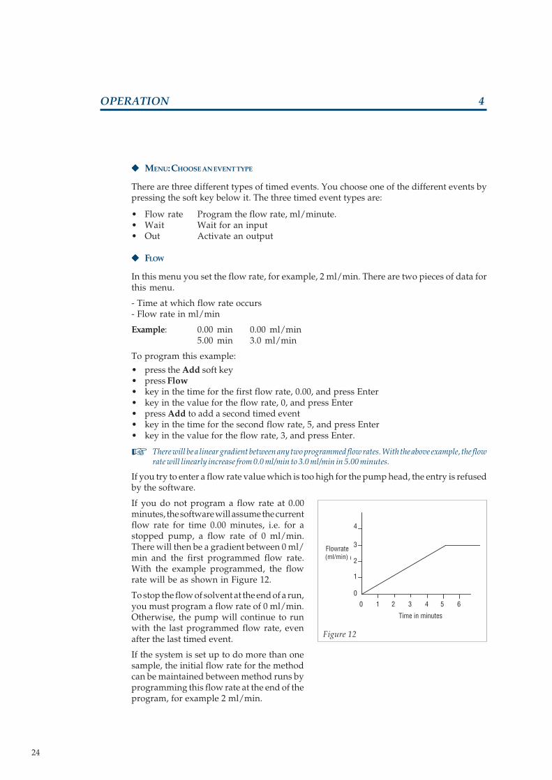
In this menu you set the flow rate, for example, 2 ml/min. There are two pieces of data forthis menu.
- Time at which flow rate occurs- Flow rate in ml/min
Example: 0.00 min 0.00 ml/min5.00 min 3.0 ml/min
To program this example:
• press the Add soft key• press Flow• key in the time for the first flow rate, 0.00, and press Enter• key in the value for the flow rate, 0, and press Enter• press Add to add a second timed event• key in the time for the second flow rate, 5, and press Enter• key in the value for the flow rate, 3, and press Enter.
There will be a linear gradient between any two programmed flow rates. With the above example, the flowrate will linearly increase from 0.0 ml/min to 3.0 ml/min in 5.00 minutes.
If you try to enter a flow rate value which is too high for the pump head, the entry is refusedby the software.
If you do not program a flow rate at 0.00minutes, the software will assume the currentflow rate for time 0.00 minutes, i.e. for astopped pump, a flow rate of 0 ml/min.There will then be a gradient between 0 ml/min and the first programmed flow rate.With the example programmed, the flowrate will be as shown in Figure 12.
To stop the flow of solvent at the end of a run,you must program a flow rate of 0 ml/min.Otherwise, the pump will continue to runwith the last programmed flow rate, evenafter the last timed event.
If the system is set up to do more than onesample, the initial flow rate for the methodcan be maintained between method runs byprogramming this flow rate at the end of theprogram, for example 2 ml/min.
☞
Flowrate(mL/min)
Time in minutes
0
1
2
3
0 1 2 3 4 5 6
4
(ml/min)
Figure 12

25 25
MODEL 307 PISTON PUMP
OPERATION 4
Method Program
Flow rate
Last timed event
Flowrate 2mL/min
Program loopsand waits forthe next sample
"
"
Output Contact
LInk to new fileafter last sample
Flowrate 0mL/min
Wait for signalfrom sampler
Stop flow
"
At the end of all the samples, link to anotherfile to completely stop the flow of liquid. SeeFigure 13.
◆◆◆◆◆ WAIT
In this menu you can make the program waituntil Input # 1 is activated. This is used to stopthe program until another piece of equipmentis ready, for example an auto-sampler or afraction collector. There are two pieces of datafor this menu.
- Time at which the pump will wait for an input- Waiting for an open contact or a closed contact
Example: 2.00 min Wait #1 Closed.
To program this example:• press the Add soft key• press Wait• key in the time for the wait to begin, 2.00,
and press Enter• press close
The program waits at time 2.00 minutes until input #1 is closed. If input #1 is already closedat time 2.00 mins, the program will continue. If input # 1 is not closed, the program will wait.During the time that the program is waiting, the display will show the total run time andthe time that it has been waiting.
If a pump is waiting for an input, pressing Cancel will simulate an input and the programwill continue.
◆◆◆◆◆ OUT
In this menu, you can program each of the outputs in the system to open or close. The outputsare numbered 1, 2, 3 and 4 and are used to send signals to other equipment in the system,for example an auto-sampler or a chart recorder. By having the output operations as partof the method program, the same sequence of contacts is repeated every time the methodprogram is run.
There are three pieces of data for this menu.- Time at which output is operated- Output number- Output opened, closed or pulsed
Each of the outputs can be made to open, close or pulse. Pulse means that the output willchange its current state for 0.6 of a second.
Example: Screen 1 3.00 min Output 2Screen 2 Open Close Pulse
To program this example:
• press the Add soft key• press Out.• key in the time for the output to operate, 3.00, and press Enter.• key in the output number, 2, and press Enter.
Figure 13

26 26
MODEL 307 PISTON PUMP
4OPERATION
The display will change to Open, Close or Pulse.
• press the soft key below close
◆◆◆◆◆ READING/WRITING/EDITING TIMED EVENTS
The three different types of timed event have been explained above. At the end of program-ming each event, the menu gives you five options. These options are explained below.
Next: displays the next timed event in the sequence. If there are no more events, it displaysEnd of file.
Prev: displays the previous timed event in the sequence. If there are no more previousevents, it displays Beginning of file.
Add: brings you to the Choose an event type menu to allow you to add another event to thepresent program.
Del: deletes one timed event in the program. As a safeguard it asks you, Delete this point?Press Yes to delete the event or No to return to the original menu.
End: leaves the software for programming timed events. The pump displays Solventconsumption in ml for one complete run of the method program. The minimum valueis < 0.1ml and the maximum value is > 999ml.
Press Quit to go to the Ready-to-Run Screen. You have now finished creating a programmethod file. Before running a method program, you should program each of the four safety/error files.
PROGRAMMING THE ERROR FILES
The error/safety files are used to control thepumping system if there is an error. If an erroroccurs, the method program is stopped and thesafety/error program is started. The number andfunction of each file is listed opposite.
These programs are created in exactly the same way as a method program. To program the lowpressure safety error file, select file 11 and enter the sequence of flow rates and input/outputoperations that you require when there is a low pressure error. Similarly, enter a program for the highpressure error file, Input # 2 error file and the power failure error file. The Input # 2 contact can beconnected to an external safety device such as a temperature or pressure measurement system.
An example of simple programs for the high and low pressure error files are given in programexamples at the end of this section.
LOW PRESSURE ERROR FILE
If the pressure goes below the low pressure limit the sequence of events is as follows.
If the low pressure error file (11) contains no program, the method program will stop andcannot resume until the operator presses the Pause soft key followed by End.
6
File Name Function
11 Low File runs after a low pressure error12 High File runs after a high pressure error13 Input File runs if input # 2 is activated14 Power File runs after a power failure
6.1

27 27
MODEL 307 PISTON PUMP
OPERATION 4
If the low pressure error file contains a program, the method program will link to this fileand will run it. After file 11 is finished, if there is a link to another file, this new file will startto run. If there is another low pressure error during file 11, the pump will stop and cannotresume until the operator presses the Pause soft key followed by End.
HIGH PRESSURE ERROR FILE
If the pressure goes above the high pressure limit, the sequence of events is as follows:
If the high pressure error file (12) contains no program, the pump stops at the instant thepressure rises above the limit. If the pressure drops below the limit again, the pump willrestart. This cycle will continue indefinitely.
If the high pressure error file contains a program, the pump stops and waits for the pressureto drop below the high pressure limit contained in File 12. When the pressure is below thislimit, file 12 will begin to run. After file 12 is finished, if there is a link to another file, thisnew file will start to run. If there is another high pressure error during file 12, the pump willstop until the pressure drops below the limit and will then restart. This cycle will continueindefinitely.
INPUT # 2 ERROR FILE
When input # 2 is activated, it causes the following sequence of events.
If there is no program in file 13, activating input # 2 will have no effect and the methodprogram will continue.
If there is a program stored in File 13, when input # 2 is activated, File 13 will start. File 13will start to run even if the system was not previously running. If there is a link to anotherfile at the end of the program, the linked file will start to run.
POWER FAILURE ERROR FILE
The power failure error file will only operate if there is a power failure while a methodprogram is running. The sequence of events after a power failure is as follows:
If there is no program stored in File 14: after the power is restored, the program will go backto the start of the method file and wait for a start input. If there is more than one file in themethod, i.e. one file is linked to another, the program will go back to the beginning of thefirst file in the method.
If there is a program stored in file 14: after the power is restored, the program in file 14 willbe run. If there is a link to another program at the end of file 14, the linked file will start torun. If the alarm is on, it will sound.
If there is a power failure in the Flow or Dispense modes, it has the same effect as if the pumpwas turned off and turned on again. The screen presented will be the Ready-to-Run Screenof the last used mode.
6.2
6.3
6.4

28 28
MODEL 307 PISTON PUMP
OPERATION 4
7 RUNNING A METHOD PROGRAM
At the end of programming the method and error files, the software returns to a Ready-to-RunScreen. The top left corner will indicate which Ready-to-Run screen you are in. To go to theProgram mode Ready-to-Run Screen:
• press Menu
• press Mode
• press Prog
The pressure can be displayed in 3 units, bar, MPa or kpsi. To change the units , press the softkey directly below bar. The units will change to MPa. Press the soft key again to change the unitsto kpsi. Press the soft key again to change the units back to bar.
The Ready-to-Run Screen displays the present file number, the pressure, and gives you 3 softkey options, Cond, Menu and Run. You can go to any file by keying in a new number andpressing Enter.
• The Cond soft key brings you to the part of the software which is used to condition thecolumn. You program a ramp time and a flow rate. The initial conditions are the existingconditions for the pump, i.e. for a pump which is not running 0 ml/min. The flow rateprogrammed should be the flow rate that is required at the start of the method program. Theflow rate is then ramped from 0 ml/min to the initial flow rate for your method program.
• press Cond
• Enter the ramping time and press Enter
• press Flow
• Enter the flow rate for the end of the ramp time
Press Run to start the conditioning of the column. The pump will ramp to the flow rate that isprogrammed in the time programmed. The values for time, flow rate can be changed duringthe conditioning. At the end of the ramp time, the flow rate will remain constant. Note that youcan leave the conditioning of the column and create a program without interfering with theconditioning of the column.
After pressing Run, the display changes to give you the choice of Roll, Stop or Quit. PressingRoll displays in turn the time for the ramp and the flow rate.
This part of the software is also used at the end of a method program to clean the column. Theinitial conditions will be the final flow rate which existed at the end of your method program.You can ramp the flow rate down to 0 ml/min to completely clean the column.
• The Quit soft key brings you to the Select Menu Item menu. This gives you access to thepump setup parameters, the pump I/O parameters and the method file. Press this keyto verify or change the value of any parameters in these sections.
• The Run key starts the program running. When this key is pressed, the display changes.The figure in the top left hand corner is the file number. The number in parentheses isthe loop number. If there is more than one loop in your program, the present loop numberwill be displayed here. The first time displayed is the actual running time. The secondtime displayed is the total running time for the method program.

29 29
MODEL 307 PISTON PUMP
OPERATION 4
One complete method program is stored in a file. The values for the five parameters; Refill, Compressibility, PumpHead Size, High pressure limit and Low pressure limit for that program are also stored in the same file. If youlink two or more files together, you must ensure that they all have the same values for these parameters.
If you link files together which have different values, the pump will not start. After pressingRun the display will give you the message Note ! Setup has changed since file creation. PressingOk gives you the choice of which setup parameters to keep by asking the question Keep originalsetup ? Yes - No. If you choose Yes, the values which are stored in the first file in the sequenceof files will be loaded into all of the files which are linked together. If you choose No, the valueswhich are currently stored in the setup parameter memory will be loaded into all of the fileswhich are linked together. In the case of linking to an error file which has different setupparameters to the method file, the parameters for the method file automatically replace thevalues which were written in the error file.
If a program has a link to a file which has nothing stored in it, the program will not start whenRun is pressed. The message Link file does not exist is displayed and the alarm will sound.
After pressing Run, the bottom line of the display changes to Roll/Menu/Pause.
Pressing Roll will display in turn:
- current file/loop number/running time and program time- current file/loop number/ flow rate- current file/current loop/total number of loops- the time that the 307 is waiting on an input
Pressing Roll once more brings you back to the Run screen.
The Menu soft key has the same function as before.
Press Pause to freeze the program. The pump will continue to run, keeping a constant flow rate.The pump will stay in this state until another key is pressed. When Pause is pressed the screenchanges to Stop/End/Cont.
• Stop will cause the pump to stop. The method file remains in the Pause state.
• End will cause the termination of the method file without stopping the pump. The pumpwill continue with the flow rate that existed when it was paused. The screen returns tothe Program mode Ready-to-Run Screen.
• Cont will cause the program to restart from the point where it was paused.
N.B. To terminate a program completely and stop the flow, you must press Stop followed byEnd. More brings you back to the previous screen. If a method program has terminated and thepumping system is still running, press Cond followed by Stop.
The input Start/Stop has the same effect as the End soft key in the Program mode.
During a method run, the setup parameters and the method program can be modified. Modifya parameter in the same way that you program it. If the flow rate is modified during a run, thenew value will take effect from the instant it is programmed.
If a flow rate is modified while the pump is running, the new flow gradient will be between the nextprogrammed point and the flow rate which existed at the instant the modification was made.
After a method program has finished, the display returns to the Ready-to-Run screen.
☞
☞

30 30
MODEL 307 PISTON PUMP
OPERATION 4
8 PROGRAMMING EXAMPLE
An example program is given below. Before running this example program, ensure that thehydraulic circuit is properly connected.
◆◆◆◆◆ EXAMPLE
In the example given in List 1, the flow rate willstart at 1 ml/min and increase to 4 ml/min after2 minutes. An output will close at 0.00 minutesto start the integrator. The method will onlyoperate once and will not link to another filewhen it is finished. Enter this program follow-ing the steps given in Program list 1.
Note that it is necessary to program a flow rateof 0 ml/min at the end of the program to stopthe flow, the flow does not automaticallystop when the program is finished. It willcontinue with the last programmed flow rate.To stop the flow at 4.00 minutes you mustprogram a flow rate of 4ml/minute at 3.99minutes and 0.00 ml/min. at 4.00 minutes.
Note on programming sheet
Appendix G contains a programming sheet which can be copied. An example of how touse the programming sheet is also given. The sequence you should follow is:
• Fill in the File Number and name
• Fill in the SETUP parameters for your system• Draw the flow rate gradients on the graphs provided, remembering to mark the axes• Fill in the table for Input/Output operations
• Write the programming steps. Finish one section before going on to the next, i.e. programall of the flow rate time points before going on to the input/output time points. The 307software will arrange all of the time points in the correct sequence.
After writing the method program, it is neces-sary to write the programs for the safety/errorfiles. Simple programs are given in list two andthree for the Low pressure error file and theHigh pressure error file. In both programs, theflow rate is programmed to be 0 ml/min. Thisis a simple example of an error file.
Enter these two error programs before runningExample 1. After entering the two pressureerror programs, the system is ready to run.Press Run. The display will look like Figure 15.When the method program is finished, theReady-to-Run screen is displayed.
Pressure reading
# 1 ( 1 )
80 bar
File number Number of loop Elapsed time Run time
Roll Menu Pause
Roll Menu Paus
0.55 / 2.00 min
Figure 15
Figure 14
Flowrate(mL/min)
Time in minutes
0
1
2
3
4
0 1 2 3 4

31 31
MODEL 307 PISTON PUMP
OPERATION 4
Program List 2
Key to press Notes
Menu
File
11/ENTER Low pressure error file
New/Edit Go to file
1/ENTER 1 Loop
None No link to other files
Flow Enter the flow rate
0/ENTER At 0.00 minutes
0/ENTER Flow rate = 0 ml/min
End Finish writing error file
Quit
Program List 3
Key to press Notes
Menu
File
12/ENTER High pressure error file
New/Edit Go to file
1/ENTER 1 Loop
None No link to other files
Flow Enter the flow rate
0/ENTER At 0.00 minutes
0/ENTER Flow rate = 0 ml/min
End Finish writing error file
Quit
Program List 1
Key to press Notes
Menu
File
1/ENTER Select file 1
New/Edit Go to file
1/ ENTER 1 Loop
None No link at end of method
Out Program the output
0/ ENTER At 0.00 minutes
1/ENTER Output # 1
Close Close output # 1
Add Add the next timed event
Flow Enter the flow rate
0/ENTER At 0.00 minutes
1/ENTER Flow rate = 1 ml/min.
Add Add the next timed event.
Flow Enter the flow rate
2/ENTER At 2.00 minutes.
4/ENTER Flow rate = 4 ml/min
End Finish writing method fileSolvent consumption: 5 ml
Quit Go to Ready-to-Run screen

32 32
MODEL 307 PISTON PUMP
5MAINTENANCE
The 307 pump has been designed to require a minimum level of care and maintenance. Inpractice, maintenance is limited to cleaning and replacing parts of the pump head.
Check valves and filters can be cleaned. Piston seals, check valves, piston assemblies, anti-extrusion gaskets and return springs can be replaced. A maintenance kit is available for eachmodel of pump head. For details about maintenance kits and procedures, see the User’s Guidefor your pump head.
The use of equipment for continuous, unattended operation is becoming more and moreimportant. For this reason, Table I gives an indication of replacement periods of maintenanceparts according to the type of use, intensive, regular or occasional. The data in Table I assumesthat the pump is working at half of its maximum flow rate and pressure. The nature of the liquidand the pump head model have only a small influence on these figures. The time between eachmaintenance operation can be viewed by using the Info soft key in the Pump menu.
Table I: Indication of replacementperiods of maintenance partsaccording to the type of use.
Parts/Use Intensive Regular Occasional(168 h/week) (40 h/week) (10 h/week)
Piston seal 2 - 3 months 6 - 9 months 1 year
Set of check valves 3 - 6 months 1year 2 years
Piston assembly 6 - 12 months 2 - 3 years 5 years
Anti-extrusion gasket 6 - 12 months 2 - 3 years 5 years
Return spring 1 year 2 - 3 years 5 years

33 33
MODEL 307 PISTON PUMP
ELECTRICAL PROBLEMS
Problem Possible cause Solution
Pump does not operate and Power cord unplugged. Check for power.power indicator does not light. Fuse blown. See ‘electrical installation’ in chapter 3.Incorrect voltage setting.
Invalid settings flashing Refill time is too long for the flow Lower the Refill time or flow rate.rate programmed
Pump does not stop at end Not programmed To stop the flow at the end of a method program,of program you must program a flow rate of 0 ml/min.
HYDRAULIC PROBLEMS
Problem Possible cause Solution
Leaks from the hole at the Defective piston seal. Replace piston seal.bottom of the pump head. Refer to User’s Guide for the pump head.
Low flow rate. Leaks. Check for leaks.
Plugged inlet filter. Clean or replace the inlet filter.Refer to User’s Guide for the pump head.
Defective check valve. Clean or replace the check valve.Refer to User’s Guide for the pump head.
Pump head not mounted properly. Check that the pump head is properly mounted.
Air bubbles appear in both inlet Loose connection of inlet tubing. Tighten the connection (but do not overtighten).and outlet tubing.
Worn flange of inlet tubing. Replace the inlet tubing.
Inlet filter partly clogged. Clean or replace the inlet filter.
Refill time is too short for the solvent. Increase the refill time.
Air bubbles appear only in Loose connection of outlet tubing. Tighten the connection (but do not overtighten).outlet tubing.
Poor dampening effect Defective membrane in the Return to Gilson.manometric module.
Eluent from the column is Manometric module membrane is Return to Gilson.coloured blue. broken.
TROUBLESHOOTING 6
1
2

34 34
MODEL 307 PISTON PUMP
APPENDIX A ACCESSORY PARTS LIST
1 STANDARD ACCESSORY PACKAGE
Ref. Qty Description
E45388 1 Pump head clamp506341 1 Terminal block connector, 14 pin610101 1 Double-ended wrench, 1/4'’- 5/16'’502046 4 Fuses 2.0 Amp type “T” slow blow for 100-120 V (5 x 20 mm)500006 1 Power cord for 100-115 V502145 4 Fuses 1.0 Amp type “T” slow blow for 220-240 V (5 x 20 mm)500005 1 Power cord for 220-240 V801171 1 Model 307 User’s Guide410085 3 Nut, 316L, 1/16" hdc, 1/4 - 28 TPI410086 3 Ferrule, 316L, 1/16" hdc430019 1 Tubing, 316L, 200 x 1.6 x 0.5 mm
Only one power cord and one set of fuses are supplied. The standardaccessory package that you receive will contain suitable parts for yourvoltage.
SPECIFIC ADDITIONAL ACCESSORIES
Ref. Description
500933 GSIOC cable500944 Four-wire electrical cable, 1.7 m length, for I/O connections.
Several units may be required according to the system configuration.267020 Mast clamp267022 Mast, aluminum, 450 x 16 mm, hexagonal
☞
2

35 35
MODEL 307 PISTON PUMP
APPENDIX B
This section explains how to control the 307 from a computer using Gilson HPLC system controllersoftware.
GSIOC FEATURES
GSIOC stands for Gilson Serial Input Output Channel. This communications channel links all ofthe Gilson modules in a system together. The system controller controls all of the modules in a systemby sending GSIOC commands to the slave modules, for example pumps or detectors. Each deviceconnected to the GSIOC channel is distinguished by a GSIOC identity number between 0 and 63.The GSIOC identity number is set by switches inside each module or by the modules software. Thecontroller communicates with one slave device at a time. The hardware and software requirementsto control a module from a computer using the GSIOC are as follows:
• An IBM PC AT, XT, PS 2 computer or compatible.
• A Gilson interface module, 506B or 605.
• A Gilson HPLC system controller software package.
To get started you must:
• Install the Gilson HPLC system controller software into the computer.• Connect the computer to the Gilson interface using the cable provided with the interface.• Connect the output from the interface to the Gilson module using a GSIOC cable.• Start the Gilson HPLC system controller software.
Consult the GSIOC technical manual and the interface manual for more details.
GSIOC COMMANDS
The GSIOC commands can be used to control Gilson modules directly from a computer or froma Gilson HPLC system controller software package. The use of the GSIOC commands iscompletely detailed in the 307 technical manual.
1
506BPC-DOSMS-DOS
RS232C cable GSIOC cable
GSIOC slave
GSIOC slave
Computer Gilson RS232C/GSIOC interface Slave Devices
2
Figure 16
GSIOC CONTROL

36 36
MODEL 307 PISTON PUMP
SOLVENT MISCIBILITY TABLEAPPENDIX C
1
ACETIC ACIDACETONEACETONITRILEBENZENEBUTYL ALCOHOLC. TETRACHLORIDECHLOROFORMCYCLOHEXANECYCLOPENTANEDICHLOROETHANEDICHLOROMETHANEDIMETHYLFORMAMIDEDIMETHYL SULFOXIDEDIOXANETHYLACETATEETHYL ALCOHOLDI-ETHYLETHERHEPTANEHEXANEMETHYL ALCOHOLMETHYLETHYL KETONEI-OCTANEPENTANEI-PROPYL ALCOHOLDI-PROPYLETHERTETRACHLOROETHANETETRAHYDROFURANTOLUENETRICHLOROETHANEWATERXYLENE
ACET
IC A
CID
ACET
ONE
ACET
ONIT
RILE
BENZ
ENE
BUTY
L AL
COHO
LC.
TET
RACH
LORI
DECH
LORO
FORM
CYCL
OHEX
ANE
CYCL
OPEN
TANE
DICH
LORO
ETHA
NEDI
CHLO
ROM
ETHA
NEDI
MET
HYLF
ORM
AMID
EDI
MET
HYL
SULF
OXID
EDI
OXAN
ETHY
LACE
TATE
ETHY
L AL
COHO
LDI
-ETH
YLET
HER
HEPT
ANE
HEXA
NEM
ETHY
L AL
COHO
LM
ETHY
LETH
YL K
ETON
EI-O
CTAN
EPE
NTAN
EI-P
ROPY
L AL
COHO
LDI
-PRO
PYLE
THER
TETR
ACHL
OROE
THAN
ETE
TRAH
YDRO
FURA
NTO
LUEN
ETR
ICHL
OROE
THAN
EW
ATER
XYLE
NE
MISCIBLE
IMMISCIBLE
SOLVENT MISCIBILITY TABLE
Solvents should be miscible, that is, they should mix with each other in all proportions. Thisis important during elution, but also during solvent changeover. For your convenience, asolvent miscibility table is provided.

37 37
MODEL 307 PISTON PUMP
OTHER DATA
For other currently used liquids at ambienttemperatures (20-25°C), the following data isgiven. This data is a result of experiments doneusing the 307 pump, the figures are not pre-sented as physical constants of scientific value.
Liquid Temperature Compressibility(°C) (Mbar -1)
Water 20 4625 4630 4540 44
Benzene 20 94-9525 96-9730 101-10340 110
Chloroform 20 97-10125 9730 108-11040 118-119
Methylene chloride 25 97
LIQUID COMPRESSIBILITY VALUESAPPENDIX D
1 BIBLIOGRAPHY DATA
The values of isothermal compressibility givenbelow can be used for the Compressibilityvalue in the pump setup menu. These valuesare given under atmospheric pressure (X0)and are expressed in Mbar -1.
The following table refers to Handbook ofChemistry and Physics, CRC Press, 60th Ed.(1979).
2
If no data is available in this Appendix for theliquid you use, and if you wish an accuracy errorwithin the specifications, you can experimen-tally determine a value to reach this goal.
To do so, use a trial-and-error empirical method. Select the initial value for LiquidCompressibility according to the following guide-lines
• For an organic solvent, take a value given for the same, or similar, chemical family• For a mixture, including salt aqueous solutions, take the value of the dominant solvent.
Pump your liquid under high pressure to obtain a significant error, preferably use a gravimetricmethod if you know the density of the liquid.
Then, with a few successive approximations, adjust the Liquid Compressibility value byassuming a linear relationship between this parameter and the resulting error.
Carbon tetrachloride 20 103-10525 106-10830 112-11340 120-122
Ethanol 20 110-11225 114-11630 118-11940 126-127
Acetone 20 123-12725 12430 13340 144-156
Methanol 20 121-12325 125-12730 129-13040 138
n-Heptane 20 140-14525 142-14930 150-15540 160
n-Hexane 20 150-16525 161-17130 165-18040 183
Diethyl ether 20 184-18725 195-20030 208-209
Liquid Temperature Compressibility(°C) (Mbar -1)
Liquid Liquid Compressibility(Mbar -1)
Acetonitrile 99
Tetrahydrofuran 93
Water-methanol, 10-90(v-v) 117Water-methanol, 20-80 " 86
" 40-60 " 56" 50-50 " 52" 60-40 " 46" 80-20 " 40
38 38
MODEL 307 PISTON PUMP
FLOWRATE ACCURACY PRINCIPLEAPPENDIX E
To generate the selected flow rate with high accuracy, maintained under high pressure andfor a variety of liquids, the 307 software adds two complementary corrections to the basic‘piston flow rate’. Defined from the piston stroke volume only, the piston flow rate istheoretically accurate at atmospheric pressure only.
The objective flow rate, F, is considered as the sum of three components
F = F0 + F1 + F2
F0 , the piston flow rate decreases when pressure increases;F1, the compensation flow rate for the liquid compressibility, increases with pressure; andF2 , the compensation flow rate for all other factors, also increases with pressure.
The piston flow rate, F0 , is defined by
F0 = N0 VS
with N0, number of piston cycles per unit time; and VS , piston stroke volume.
The compensation flow rate for the liquid compressibility, F1 , is calculated as a function of fivevariables
F1 = f1 (F0, VS, VD, P, X)
where VD is the volume of the dead space inside the compression chamber;P, the operating pressure; andX, the compressibility of the liquid under the pressure P.
In the 307 software, X is calculated using the simplified Tait equation
X =
Coefficient c varies only slightly with the nature of the liquid. It is a constant included in the software.Coefficient d is calculated from the Liquid Compressibility at atmospheric pressure, X0 (forP=0), entered by the user as a «set-up» parameter.Values of X0 for some common solvents are tabulated in Appendix D.Operating pressure, P, is continuously transmitted to the pump by the Manometric Module(pressure feedback).
The complementary compensation flow rate for all other factors, F2, is defined as the difference
F2 = F - (F0 + F1)
It was measured and the experimental results were expressed using a simple function ofoperating pressure P
F2 = f2 (a, b, P)
Coefficients a and b were determined for each pump head. They are manufacturing constantsattached to the parameter Head Size, a second ‘setup’ parameter entered by the user.
All of these factors taken together allow the 307 to deliver a highly accurate flow rate,independent of the pump head size, type of liquid and pressure.
c P + d

39 39
MODEL 307 PISTON PUMP
APPENDIX F 307 PROGRAMMING CHART
Sele
ct m
enu
item
Pum
p I/
O F
ile M
ode
Qui
t
High
pre
s. li
m x
.xx
kpsi
Next
Pre
v
Q
uit
Low
pre
s. li
m x
.xx
kpsi
Next
Pre
v
Q
uit
Alar
m is
On
Next
Pre
v C
hang
e
Qui
t
GSIO
C Un
it ID
: x
x
Next
Pre
v
Q
uit
Outp
ut x
x is
ope
n
Next
Pre
v C
hang
e
Qui
t
I. Pa
use/
Prog
is w
. flo
w
Next
Pre
v C
hang
e
Qui
t
Zero
Pre
ssur
e Re
adin
g
Next
Pre
v Z
ero
Q
uit
Sele
ct o
pera
ting
mod
e
Flow
D
ispe
nse
Pr
ogra
m
Flow
rate
xxx
.xx
ml/m
in
0.00
kps
i
Men
u R
un
Flow
rate
xxx
.xx
ml/m
in
0.00
kps
i
Men
u S
top
Read
y to
run
scre
ens
Runn
ing
scre
ens
Head
Size
: x
xx
Next
Pre
v In
fo
Qu
it
Oper
atin
g tim
e:
xxxx
x h
Rese
t
Ok
Refil
l: x
xxx
ms
Next
Pre
v
Q
uit
Com
pres
sibi
lity:
x
xx
Next
Pre
v
Q
uit
Inle
t pre
ssur
e:
xx M
Pa
Next
Pre
v
Q
uit
If th
e ha
rdw
are
setu
p di
ffers
from
the
setu
p in
th
e m
etho
d, th
ese
war
ning
mes
sage
s w
ill b
e di
spla
yed
whe
n 'R
un' o
r 'Ed
it' is
pre
ssed
.
Note
: Set
up h
as c
hang
ed
sinc
e fil
e cr
eatio
n
Ok
Keep
orig
inal
set
up ?
Yes
No
Prog
ram
File
: xx
0.00
kps
i Co
nd M
enu
Run
Disp
xxx
.xx
Rate
xxx
.xx
0.00
kps
i Ti
me
Men
u R
un
Disp
xxx
.xx
Tim
e xx
x.
0.00
kps
i Ra
te M
enu
Run
Vol x
xx.x
x/xx
x.xx
ml
0.00
kps
i Ro
ll M
enu
Pau
s
Paus
ed x
xx.x
x m
in
0.00
kps
i Ro
ll
End
Con
t
Vol x
xx.x
x/xx
x.xx
ml
0.00
kps
i Ro
ll M
enu
Pau
s
Paus
ed x
xx.x
x m
in
0.00
kps
i Ro
ll
End
Con
t
Mod
el 3
07 V
2.1
Read
y to
run
scre
ens
#xx
(xxx
) xx.
xx/x
x.xx
min
0.00
kps
i Ro
ll M
enu
Pau
s
#xx
(xxx
) Pau
s. x
x.xx
min
Mor
e S
top
En
d C
ont
Vol x
xx.x
x/xx
x.xx
ml
Tim
e xx
x.xx
/xxx
.xx
min
Rate
xxx
.xx
ml/m
in
#xx
(xxx
) xx.
xx/x
x.xx
min
#xx
(xxx
) xxx
. xx
ml/m
in
#xx
Loop
s xx
x/xx
x
#xx
(xxx
) Wai
t xxx
.xx
min
Disp
ense
mod
ePr
og m
ode
IN R
UN D
ISPL
AY(R
oll)
Cond
in ru
n ?
No
Yes
#xx
(xxx
) Pau
s. x
x.xx
min
0.00
kps
i R
oll
Men
u Q
uit
Ram
ping
tim
e: x
xx.x
x m
in
Flow
S
top
Exe
c Q
uit
xxx.
xx/x
xx.x
x m
in
xxx.
xx m
l/min
xxx.
xx/x
xx.x
x m
in
0.00
kps
i R
oll
Qu
it
xxx.
xx m
in x
xx.x
x m
l/min
Solv
ent c
onsu
mpt
ion
xxxx
xx.x
ml
Q
uit
Dele
te th
is p
oint
?
Yes
No
Choo
se a
n ev
ent t
ype
Fl
ow W
ait
Out
xxx.
xx m
in x
xx.x
x m
l/min
Next
Pr
ev
Add
Del
En
d
xxx.
xx m
in O
ut #
xx C
lose
Next
Pr
ev
Add
Del
En
d
xxx.
xx m
in W
ait #
1 Op
en
Next
Pr
ev
Add
Del
En
d
Whe
n fin
ishe
d us
e: N
one
Next
Pre
v N
one
Qu
it
Copy
#xx
to #
xx (S
tatu
s)
Yes
No
Num
ber o
f loo
ps: x
xx
Next
Pre
v
Q
uit
Dele
te fi
le #
xx
Yes
No
The
'Qui
t' ke
y al
way
s re
turn
s to
the
last
use
d 'R
eady
to ru
n', '
Runn
ing'
or '
Paus
e' s
cree
ns.
Sele
ct fi
le #
xx (T
ype)
Dir
Ne
w Q
uit
Dir
Cop
y D
el
Edi
t Q
uit
Paus
e sc
reen
s

40 40
MODEL 307 PISTON PUMP
APPENDIX G 307 PROGRAMMING SHEET
File Number: Method Name
SETUP PARAMETERS
Pressure: High limit = Low limit = Units:
Loops = Link file =
Solvent Refill Comp Headsize
I/O OPERATIONS
Time Contact State Function
PROGRAM STEPS
Step No Time Event Operation Step No Time Event Operation
1 14
2 15
3 16
4 17
5 18
6 19
7 20
8 21
9 22
10 23
11 24
12 25
13
ml/min
Time (min)
FLOW

41 41
MODEL 307 PISTON PUMP
APPENDIX G 307 PROGRAMMING SHEET (EXAMPLE)

42 42
MODEL 307 PISTON PUMP
APPENDIX H TECHNICAL DATA
TYPE: Programmable reciprocating pump, with single piston interchangeable head, constantstroke and fast refill motion, internal pulse dampener, and pressure feedback.
WORKING RANGE
• Flow rate: 0.010 - 5 ml/min (programmable down to 0.5 µl/min).• Pressure: 0.1 - 60 MPa.• Temperature: 0 - 40°C for the module.
PUMP HEADS: Any Gilson model working in the above range, specifically the 5SC for standardapplications and the 10 WSC for salt-concentrated solutions (> 0.1M).
LIQUID CONTACT MATERIALS: 316L stainless steel, sapphire, ruby, PCTFE, PTFE/HDPE.
PULSE DAMPENING
• Pulsation: less than 1% with water at 1 ml/min and pressure higher than 8 MPa.• Dampener volume: 0.6 ml at atmospheric pressure, and 1.6 ml at 60 MPa.
FLOW RATE PRECISION AND ACCURACY AT 20°C OVER FULL WORKING RANGE
• Coefficient of variation: 0.1 - 0.6% with aqueous solutions or hydro-organic polar solventmixtures, and 0.3 - 1% with hydrocarbons or chlorinated volatile solvents.
• Maximum accuracy error: ± 1% with water over the full flow rate and pressure ranges.
OPERATING MODES: Constant flow rate (Flow), constant volume (Dispense), and time-basedsequence (Program).
PROGRAM MODE AND SYSTEM CONTROL
• Time: adjustable from 10 -2 to 10 4 min, with increment from 0.01 to 1 min depending onthe range used.
• Program points: up to 25, including flow rate and external events.• Flow rate: adjustable in ml/min, from 0.01% to 100% of the head maximum flow rate.• External events: 4 outputs contact closures to activate auto-sampler, integrator, fraction
collector and detector autozero, and 1 input to wait for injection.• Up to 999 program loops and program linking.• Safety functions: 4 dedicated programs, for pressure outside of selected limits, input of an
emergency signal (temperature threshold, leak detection, etc), and power failure.
MEMORY CAPACITY: 10 user’s programs and 4 safety programs.
DISPENSE MODE: Volume adjustable in ml from 10 -4 to 10 2 times the pump head size. For a 5 SChead, from 0.5 µl to 500 ml. Dispense time or flow rate can be selected.
PUMP PARAMETERS: Head number (5 or 10), liquid compressibility (0 to 2000 Mbar -1), refill time(125 to 1000 ms) and inlet pressure (0 to 10 MPa).
USER INTERFACE: 2 x 24 character LCD display. Front panel keypad. Built-in help messages.Information display for use and maintenance.
DIGITAL INTERFACE: Gilson Serial Input Output Channel (GSIOC) slave connector on rear panel.
ELECTRICAL INTERFACE: 4 inputs and 4 relay outputs on rear panel.
CONFORMITY TO NORMS (From serial 168001):Gilson's 307 Piston Pumps conform to EEC Directive 89/336/EEC for electromagneticcompatibility: Standard EN 50081-1 for emission, Standard EN 50082-1 for immunity.Gilson 307 Piston Pumps conform to EEC Directive 73/23/EEC for safety: Standards EN61010-1, UL 3101-1, and CAN/CSA C22.2 N° 1010-1.Each Piston Pump is subjected to a Dielectric Test (1500 V between live/neutral and earth)and an Earth Bonding Impedance Test (� 0.1 �).

43 43
MODEL 307 PISTON PUMP
ENVIRONMENT:Dimensions (W x D x H): 330 x 330 x 150 mm.Temperature range: 4-40°C.Humidity: Up to 80 %.Altitude: Up to 2000 m.Voltage range: 100-120 V : 220-240 V, 50-60 Hz.Electrical power: 120 VA.Weight: 11.5 kg (with pump head).Pollution: Pollution degree 2.Installation: Category II.
APPENDIX H TECHNICAL DATA

44 44
MODEL 307 PISTON PUMP
INDEX
Columncleaning 29conditioning 29
Compressibility 15
Dispense mode 20
Electrical connectionscontrol 9power 7
Error fileslayout 21operation 26programming 26
Flow mode 19
Fuserating 7replacement 7
GSIOC305 commands 35identity number 17
Installationcontrol connections 9electrical 7hydraulic 9input/output connections 9mechanical 8positioning the modules 9
Mast installation 8
Outputsinitial conditions 17programming 25
Pressurehigh limit 16low limit 16setting to zero 18
Priming 12
Program mode 21
Programming a method 23
Pump headinstallation 8maintenance 32size 15
Refill time 15
Technical Data 42
Timed eventflow rate 23operate an output 25wait for an input 25
Troubleshootingelectrical problems 33hydraulic problems 33
Voltage selection 7