305 pump user’s guide - gilson, inc head maintenance ... given in this document, the 305 pump...
TRANSCRIPT

305 PumpUser’s Guide


305 Piston PumpUser’s Guide
LT801152M/©2003 Gilson SAS All rights reserved September 2003


Table of Contents-1
Table of Contents
Safety
1 IntroductionUsing this Manual ........................................................................ 1-2Unpacking ...................................................................................... 1-3
2 DescriptionFront View ...................................................................................... 2-2Keypad ............................................................................................ 2-3Rear View ....................................................................................... 2-4
3 InstallationElectrical Installation - Power ..................................................... 3-2
Inserting the Fuses .................................................................. 3-2Selecting the Voltage ............................................................... 3-2
Mechanical Installation ............................................................... 3-4Pump Head Installation ........................................................ 3-4Mast Installation ..................................................................... 3-4
Positioning the Modules .............................................................. 3-6Manual Injection System ....................................................... 3-6Auto-Analytical System ......................................................... 3-6Auto-Preparative System ....................................................... 3-7
Control Connections ..................................................................... 3-8Connecting the Manometric Module ................................... 3-8Connecting the 306 to Other Gilson Modules .................... 3-8Connecting the 305 to a 307 ................................................... 3-9
Hydraulic Connections .............................................................. 3-10Input/Output Connections ...................................................... 3-11
Operation of the Inputs ........................................................ 3-11Output Controls .................................................................... 3-13
4 OperationPriming the Pump Head .............................................................. 4-2Using the Keypad .......................................................................... 4-3Setting Up the Pump ..................................................................... 4-4
Set Up Pump Hardware (PUMP) .......................................... 4-5Mode Selection ............................................................................. 4-15
Running the Pump in Flow Mode ...................................... 4-15Running the Pump in Dispense Mode .............................. 4-17Running the Pump in Program Mode ............................... 4-20

Table of Contents-2
File Selection ................................................................................. 4-22Directory .................................................................................. 4-23Copy ......................................................................................... 4-23Delete ....................................................................................... 4-23Edit/New ................................................................................ 4-23Quit .......................................................................................... 4-23
Programming a Method ............................................................. 4-24Menu: Number of Loops ...................................................... 4-24Menu: When Finished, Use ................................................. 4-24Menu: Choose an Event Type ............................................. 4-25Mixt .......................................................................................... 4-25Flow.......................................................................................... 4-26Wait .......................................................................................... 4-27Out ........................................................................................... 4-28Inj .............................................................................................. 4-29Reading/Writing/Editing Timed Events ......................... 4-30
Programming the Safety Files ................................................... 4-31Low Pressure Safety File (File 11) ........................................ 4-31High Pressure Safety File (File 12) ...................................... 4-32Input #2 Safety File (File 13) ................................................ 4-32Power Failure Safety File (File 14) ....................................... 4-32
Running a Method Program ..................................................... 4-34Cond Soft Key ........................................................................ 4-34Run Soft Key ........................................................................... 4-35
Programming Examples ............................................................ 4-38Example 1 ............................................................................... 4-38Example 2 ............................................................................... 4-40
5 Maintenance and TroubleshootingPump Head Maintenance ........................................................... 5-2Troubleshooting ............................................................................. 5-3
Electrical Problems .................................................................. 5-3Hydraulic Problems ................................................................ 5-3
AppendicesAppendix A - Accessory Parts Lists .......................Appendix A-1
Standard Accessory Parts List ...........................Appendix A-2Additional Accessory Parts List ........................Appendix A-3
Appendix B - GSIOC Control ................................. Appendix B-1GSIOC Features ................................................... Appendix B-2GSIOC Commands ............................................. Appendix B-3
Appendix C - Twin-pump Systems .......................Appendix C-1Appendix D - Reference Informations ...................Appendix D-1
Solvent Miscibility Table ...................................Appendix D-2Liquid Compressibility Values ........................Appendix D-3Flow Rate Accuracy Principle ...........................Appendix D-5
Appendix E - 305 Programming Sheet .................. Appendix E-1Appendix F - Technical Data ...................................Appendix F-1
Type of Pump ........................................................Appendix F-2Working Range & Performance Data ................Appendix F-3Control and Interfaces .........................................Appendix F-5Environmental Conditions ................................Appendix F-7

Safety-1
Safety
Read this section carefully before installing and operating the pump.
For safe and correct use of the pump, it is essential that both operating and servicepersonnel follow generally accepted safety procedures as well as the safety instructionsgiven in this document, the 305 Pump User’s Guide.
The instrument described in this document is 305 high pressure piston pump for use insingle or multi-pump applications. It can control Gilson Model 306 slave pumps inmulti-pump applications. It should only be used in the laboratory or similar indoorenvironment, by qualified personnel. If the instrument is used in a manner not specifiedby Gilson, the protection provided by the instrument may be impaired.
Ensure that the ventilation fan on the Piston Pump operates and is not obstructed whenthe instrument is installed.
Voltages present inside the instrument are potentially dangerous. If there is a problemwith the instrument, the power cable should be removed until qualified service personnelhave repaired it. This is to prevent anyone from inadvertently using the instrument,thus causing possible harm to themselves, or damage to the instrument itself.
The leakage current of this instrument is within the limits allowed by safety standardsfor laboratory equipment. An efficient ground connection is imperative for the physicalprotection of the user.
Power supply cord reference 7080316106 is for use in France and Germany. Powersupply cord reference 7080316105 is for use in USA and Canada. For other countriescontact your local Gilson distributor. You must only use the type of fuse described andspecified in this document: 2.0 Amp type “T” slow blow for use where the powersupply is between 100 V and 120 V, 1.0 Amp type “T” slow blow fuse for use where thepower supply is between 220 V and 240 V.

Safety-2
Safety
However, adequate protection including clothingand ventilation must be provided if dangerousliquids are used. In case of incidental spillage, carefullywipe with a dry cloth, taking into account the natureof the spilled liquid and the necessary safetyprecautions.
Cleaning, installation, dismantling, maintenance,adjustment and repair should only be performed bypersonnel trained in such work, and who are awareof the possible dangers involved. This instrumentmust not be sterilized, using an autoclave, or anyother mechanical device. When you need to cleanthis instrument, use one of the three followingmethods:
1 - a clean dry cloth,2 - a cloth dampened with water,3 - a cloth dampened with soapy water.
If a cloth dampened with soapy water is used toclean the pump, only domestic soap may be used.No other form of detergent or chemical may be used.
These electronic and hazard symbols appear on thepump:!
Symbol Explanation
Alternating current
PROTECTIVE CONDUCTORTERMINAL
On (Supply switch)
Off (Supply switch)
Caution, risk of electric shock
Caution (refer to User’s Guide)
I
O
~

1-1
Introduction 1
Gilson’s 305 Master pump conform to the standard specified in the ‘Declaration ofConformity’ certificate (reference LT801354) supplied with the instrument.
The 305 Master pump is designed as a system controller. It can operate as a stand-aloneisocratic pump or as a system controller, to deliver fluids (liquids or liquefied gas whenspecially equipped). As a system controller, the 305 Master pump controls a completepumping system, elution pumps and injection pump.
The 305 Master pump can operate in three different modes. These modes are:
Flow: The 305 pump provides a constant flow rate. The pump starts when the Runkey is pressed and stops when the Stop key is pressed. The flow mode is forisocratic use only.
Dispense: The 305 dispenses a specified volume. The pump starts when the Start key ispressed and stops when the specified volume has been dispensed. Thedispense mode is for isocratic use only.
Program: The 305 controls a multi-pump system with up to 2 slave elution pumps and1 slave injection pump. In this mode, the 305 Master pump can creategradients of flow rate and composition, open and close outputs to controlother instruments and wait for signals from other instruments.
The operation of each mode is explained in Chapter 4.
The present software version is 3.01.
1-2
Introduction 1U
sing
this
Man
ual Using this Manual
The 305 piston pump is a precision instrumentwhich is simple and easy to use. To gain themaximum from the instrument, you should:
• Read the description of the instrument in chapter 2.• Install the instrument as shown in chapter 3.• Follow the operating instructions given in chapter 4.

1-3
Introduction 1U
npacking
UnpackingThe 305 piston pump is packed in a single carton.Upon receipt of your instrument, carefully unpackthe unit and inspect it for possible damage. Thisshould be done immediately. Check the contents ofthe carton against the parts list to verify that allparts are included and undamaged. The parts list isgiven in Appendix A. Do this now, even if the unitwill not be used immediately. Report any damage tothe responsible carrier immediately. Read thedescription in chapter 2 to become familiar with theinstrument, its different parts and their names.

1-4
Introduction 1

2-1
Description 2
This chapter describes the physical layout of the 305 piston pump. It describes the mainbody of the 305 and the position of the electrical connectors on the rear panel.

2-2
Description 2Fr
ont V
iew Front view
The figure below shows a front view of the 305 Masterpump with a pump head mounted. There is a keypadwhich consists of a display, a numeric keypad andsoft keys for programming the 305. The pump headis mounted on the right hand side.
Display
Keypad
Pump head outlet
Pump head
Pump head clamp
Pump head inlet Side grip
Side screw

2-3
Description 2K
eypad
KeypadThe figure below shows the keypad with thenumeric keys, the display and the soft keys.
Power-on indicator Display
Softkeys
PRIME HELP CANCEL ENTER
Numeric keypad
Display: two 24-character lines are used to dispalyparameters commands and messages.
Softkeys: their functions are determined by thesoftware and may change from menu to menu. Thepresent functions are displayed above each softkey.
PRIME: the pump runs at its maximum flowrateuntil you press the STOP stoftkey.
HELP: dispays advice and instructions at any time,with no effect on the operation of the pump.
CANCEL: cancels your last entry before it has beenstored in the memory.
ENTER: confirms a selection or parameter value andstores it in the memory.
Numeric keypad: this is used to key in valuesduring programming. The parameter being modifiedis always underlined with a flashing cursor.

2-4
Description 2
Rear ViewThe figure below shows a rear view of the 305 withthe electrical connectors. The function of eachconnector is as follows:
• GSIOC TO SLAVE PUMPConnection to a slave pump.
• GSIOC FROM CONTROLLERConnection to a computer.
• PRESSURE CONTROLConnection to the manometric module.
• INPUT/OUTPUT CONTROLConnector for the 305 inputs and outputs.
• Power switchOn/off power switch.
• Power receptacleVoltage selector and fuse holder.
Rea
r Vie
w
Powerswitch
Powersocket
Fuse holder andvoltage selector
Input/Output socket
Pressure controlGSIOC socket, to be usedif the 305 is a slave pump
GSIOC socket, to be used ifthe 305 is the Master pump
Fan opening

3-1
Installation 3
This chapter describes how to install the 305 Master pump. It is recommended that youfollow the installation instructions in the order that they are presented in the manual.

3-2
Installation 3El
ectr
ical
Inst
alla
tion
- Pow
er Electrical Installation - Power
For safety reasons, the 305 is shipped without thefuses installed and with the voltage selector in the220/240 Volt position. You must:
• Insert the correct fuses.• Set the voltage selector to your local voltage.
Inserting the Fuses
Ensure that the power cord is not connected beforestarting to install the fuses. Follow the procedurebelow to install the two fuses.
• The voltage selector and fuse holder is locatedunder neath the power socket. See opposite figure.Pull the voltage selector out of the powerreceptacle. This is done by gently levering theselector out using a small screwdriver.
• Pull out the drawer as shown in the figureopposite. Insert the first fuse into the clips.
• Push the drawer back into position.
• Pull out the drawer for the second fuse which ison the other side of the voltage selector. Insert thesecond fuse into the clips.
The instrument requires two fuses to be installed.The type of fuses required are: 2.0 Amp type “T”slow blow for 100 -120 V, 1.0 Amp type “T” slowblow for 220-240 V.
For safety reasons, piston pumps are deliveredwithout fuses installed. Fuses must be installed bythe user upon delivery.
Selecting the Voltage
The 305 can be set to operate at 100/120 volts or220/240 volts. The different voltages are selecteddepending on the orientation of the fuse holder.
To set the voltage to 100/120 volts:
Insert the fuse holder with the numbers 110/120 onthe bottom, facing the small white arrow.

3-3
Installation 3Electrical Installation - Pow
er
To set the voltage to 220/240 volts:
Insert the fuse holder with the numbers 220/240 onthe bottom, facing the small white arrow.
For safety reasons, do not connect the power corduntil you have finished assembling the instrument.

3-4
Installation 3
Mechanical InstallationThis section explains how to install the pump head,the mast clamp and mast. The pump head and mastclamp for each pump should be installed beforepositioning the modules.
Pump Head Installation
The pump head is shipped in a hard case to protectit during transit. Unpack the pump head from itscase and check that all of the parts are included.Follow the procedure below to install the pump head.
• Insert the pump head into the front aperture ofthe pump. See the opposite figure. The notch atthe bottom of the pump head body must be fittedonto the matching pin on the pump, just belowthe aperture. This notch ensures that the inlet portis on the bottom and the outlet port is on the top.
• Holding the pump head in place with one hand,set the clamp diagonally over the head.
• Turn the clamp clockwise into position in the slotson both sides of the pump head.
• Tighten the thumb screw until the clamp holdsthe pump head securely. Make sure that the clampends are secured in their slots on both sides.
See the pump head User’s Guide for more informationon the pump head.
Mast Installation
The mast is used to stabilise a system when severalmodules are stacked on top of each other. It can alsoused to hold the prime/purge valve and a manualinjection valve. The mast clamp should be installedbefore positioning the 305 Master pump in a system.The mast is added after all of the modules have beenput in place. Follow the procedure below to install themast clamp.
• Remove the side screw holding the module cover.See the opposite figure.
• Screw on the mast clamp.
Mec
hani
cal I
nsta
llatio
n

3-5
Installation 3M
echanical Installation
Fix one clamp onto each pump in the system. Afterall the modules have been positioned, the stainlesssteel mast can be secured within the clamps. Thelower end of the mast should be level with thebottom of the lowest pump.

3-6
Installation 3Po
sitio
ning
the
Mod
ules Positioning the Modules
Before putting each module in position, make surethat each module is ready, i.e. that the fuses havebeen installed and that any mechanical installationis finished.
The physical positioning of each of the modules inyour system will depend on your type of system.Some suggested layouts are given below. Theselayouts have been desigend to make the hydraulicand electrical connections as simple as possible.
Manual Injection System
This is a binary gradient system with two pumps,one manometric module, one mixer and onedetector. The pumping system consists of one 305Master pump and one 306 slave pump. The differentmodules should be located as shown in the figureopposite.
The detector is located at the bottom of the stack andthe pumps and other modules are positioned over it.The 305 Master pump should be the top pump. Thismakes the hydraulic connections to the manometricmodule as short as possible which gives the bestresults. It is also easy to read the display and to usethe keypad.
Auto-Analytical System
This is a binary gradient system with two pumps,one manometric module, one mixer, one detectorand one auto-sampler.
The pumping system consists of one 305 Masterpump and one 306 slave pump. The 305 Masterpump should be the top pump. This makes thehydraulic connections to the manometric module asshort as possible which gives the best results. It isalso easy to read the display and to use the keypad.The figure opposite shows the layout with a Gilson231-402 auto-sampler. The next figure shows thelayout with a Gilson 232-402 auto-sampler.

3-7
Installation 3Positioning the M
odules
Auto-Preparative System
This is a binary gradient system with two elutionpumps, one injection pump, one manometric module,one mixer, one detector and one fraction collector.
In this configuration, automatic injection isperformed by the injection pump, locatedbelow the master pump.
The pumping system consists of one 305Master pump and two 306 slave pumps. The305 Master pump should be the top pump.This makes the hydraulic connections to themanometric module as short as possiblewhich gives the best results. It is also easy toread the display and to use the keypad (seethe opposite figure).

3-8
Installation 3C
ontr
ol C
onne
ctio
ns Control ConnectionsAfter positioning all of the modules in the system, it isnecessary to connect each module to the systemcontroller. Two types of electrical connection mustbe made.
• The manometric module must be connected to the305 Master pump.
• All of the slave pumps must be connected tothe Master pump using the GSIOC cable provided.
Connecting the Manometric Module
The manometric module has two functions, todampen the pulsations of the pump and to supplythe current pressure value to the Master pump. TheMaster pump needs this information to accuratelycontrol the flow rate and to ensure that the systempressure is not above or below the control limitsentered in the program. The opposite figure showsthe connection for the manometric module.
Connecting the 305 to other GilsonModules
The 305 Master pump and the other modules in thesystem communicate using the Gilson Serial Input/Output Channel (GSIOC). Each slave modulecontrolled by the 305 Master has a GSIOC connectoron its rear panel and is connected to the 305 Masterusing the GSIOC cable provided. It is possible toconnect the 305 Master pump to two slave modulesusing this cable. If there are more than two slavemodules, two GSIOC cables can be connected together.The opposite figure shows the GSIOC connections fora system with 3 elution pumps and on injection pump.
To connect the 305 Master pump to the slave pumps:
Connect the socket marked GSIOC TO SLAVE onthe rear panel of the 305 Master pump to the slavepumps using the GSIOC cables provided.
Each slave pump and the injection pump must havethe GSIOC ID number set as appropriate, see theopposite table. Ensure that their respective ID numbershave been correctly set. This can be checked by
Slave pump I.D. Number
B 2C 3Inj 4

3-9
Installation 3
looking at the rear of the 306 pumps and ensuringthat the correct switch (2, 3 or 4) has been switchedinto the bottom position. The switches are labelledREMOTE, and are numbered 1 to 8 from left to right.
Connecting the 305 to a 307
The 305 Master pump can directly control a 307pump without the addition of a manometric moduleand with pressure display on the 305 screen.
In this case, the value 2 must be entered in the 307software as a GSIOC identification number for the307 pump. If this is omitted, the pressure valuedispalyed by the 305 will remain at zero. Theremedy is to first correct the 307 identification, thento switch off and on the two pumps.
Hydraulically, the 307 should normally be used forsolvent B, and set-up 1 is recommended (ratherthan set-up 2) for the following reasons:
• As it is usually the case in Gilson gradientsystems, solvent B, of higher elution strengththan A (and normally more expensive), does notenter the pulse dampener. This makes purgeeasier.
• Tubing is shorter and fewer elbows are required.
Control C
onnections
Set-up 1
Set-up 2

3-10
Installation 3H
ydra
ulic
Con
nect
ions Hydraulic Connections
The hydraulic connections for the 305 pump headare made using the tubing provided in the standardaccessory package. Connect the 305 pump headinput with the inlet tubing assembly provided withthe pump head. The connections to the 305 pumphead output should be made using stainless steel,titanium tubing or plastic tubing.

3-11
Installation 3Input/O
utput Connections
Input/Output ConnectionsFor coordination with surrounding equipment,electrical contacts are used.
The input/Output connector is a 14-pin terminalblock connector. Connections are made to the inputsand outputs using the connector supplied in thestandard accessory package.
The function and pin numbers for each input andoutput are as follows.
Operation of the Inputs
To activate an input, you must connect it to groundor 0 V. This is usually done using a relay output,with one side connected to 0 V (Pin 1) and the otherside connected to the input. When the output isclosed, the input is connected to 0 V and is activated.Each of the four inputs are described in detail in thefollowing pages.
Inputs Outputs
Start/Stop Out # 1Pause/Resume Out # 2
IN # 1 Out # 3IN # 2
Pin # Function
1 Ground2 Start/Stop Input3 Pause/Resume Input4 IN # 1 Input5 IN # 2 Input6 Out # 3 Output7 Out # 3 Output8 Out # 2 Output9 Out # 2 Output
10 Out # 1 Output11 Out # 1 Output12 Gradient Profile Out13 Gradient Profile GND14 Not connected
In the Program mode, Stop doesnot stop the flow, it only stopsthe program from continuing.The flow will continue with theflow rate and composition whichexisted when the stop input wasactivated. The program will re-start from the beginning whenthe contact is opened. At the endof each operation, the solventconsumption will be displayed.In the Dispense mode, the Startinput can be activated with apulse.
Not used
1 2 3 4 5 6 7 8 9 10 11 12 13 14
305 Input/Output Connector
Start/Stop InputPause/ResumeWait for Input # 1Activate Input # 2
GND GND
GradientProfileInputs to the 305
Outputs contactfrom the 305
The Start/Stop Input
The start/stop input is used to start and stop the 305pump using an external relay contact.This input is onlyactivated whenthe input changesfrom open toclosed or fromclosed to open.The operation foreach mode isgiven opposite.
Mode Input Result
Flow Closed Start FlowOpen Stop Flow
Dispense Closed Start DispenseOpen Stop Dispense
Program Closed Start ProgramOpen Stop Program

3-12
Installation 3
The Pause/Resume Input
The Pause/Resume input is used topause and restart the 305 pump usingan external contact.
This input is only activated whenthe input changes from open toclosed or from closed to open. Theoperation of each mode is shown inthe table opposite.
In the Program mode, this input can be configuredto obtain a pause with or without flow. This choiceis offered inside thesoftware branch I/O,within the screen :
The default value is with (w) flow, press change toobtain a pause without (w.o) flow. During a pausewith flow, the flow will continue with the flow rateand composition which existed when the pauseinput was activated. The program will continuefrom the same point in the from the same point inthe program when the resume contact is opened.The pause without input is of particular interestwhen the 305 is used as a metering pump to feed areagent in high pressure reactors. In this application,the 305 can wait for correct values of externalparameters (temperature, pressure, composition)before adding more reagent.
The IN # 1 Input
This input only operates inthe Program mode. It is fullyprogrammable. It can be usedto make the program waituntil a piece of equipment isready.
An example for this input iswhen the pumping system iswaiting for a signal from asample injector or a fractioncollector.
Inpu
t/Out
put C
onne
ctio
ns
Mode Input Result
Flow Closed Pause FlowOpen Resume Flow after Pause
Dispense Closed Pause FlowOpen Resume Flow after Pause
Program Closed Pause ProgramOpen Restart Program
I. Pause/Prog is w. flow
Timed event Input Result
Wait input # 1 Closed Open Wait IN # 1 is closed
Wait input # 1 Closed Closed Continue with program
Wait input # 1 Open Open Continue with program
Wait input # 1 Open Closed Wait IN # 1 is open
For more information, seeProgramming the inputs inChapter 4.

3-13
Installation 3
The IN # 2 Input
This input is activated when closed. Activatingthis input while Program mode is selected, causesFile 13 to run. If nothing is programmed in File 13or if File 13 is already running, this input will beignored. This input can be used to start a specialprogram if an external signal is received, forexample a warning signal from a temperaturemeasuring system.
Output Controls
The 305 Master pump has three output relays.
Each output relay consists of two terminals.
These terminals can be connected together (contactsclosed) or not connected together (contacts open).
All of the outputs are electrically isolated from eachother and from ground. These contacts can be usedto control other equipment, e.g. to turn on or offanother piece of equipment.
Input/Output C
onnections
Mode Input Result
Program Open No effect
Program Closed Start File 13
For more information, seeProgramming the outputs inChapter 4.

3-14
Installation 3
4-1
Operation 4
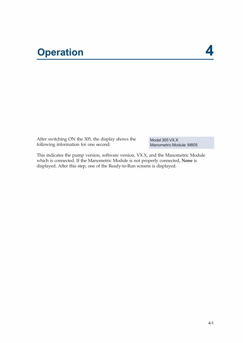
After switching ON the 305, the display shows thefollowing information for one second:
This indicates the pump version, software version, VX.X, and the Manometric Modulewhich is connected. If the Manometric Module is not properly connected, None isdisplayed. After this step, one of the Ready-to-Run screens is displayed.
Model 305 VX.XManometric Module: M805
4-2
Operation 4Pr
imin
g th
e Pu
mp
Hea
d Priming the Pump Head
Do not run the pump when the pump head is dry.This can result in severe pump head damage.
Check that the solvent bottle is filled with HPLCgrade, degassed solvent or buffer. Immerse the inlettubing filter into the solvent reservoir. Make sure thatall of the hydraulic connections are properly made.
Before priming, all electrical connections must bemade, and all hydraulic connections in place. Allpumps present in the system, A, B, C and Inj canbe primed in the Program Mode using the 305Prime command. However, the pumps must beconnected and declared present in the “SetupPump Hardware” procedure, page 4-5.
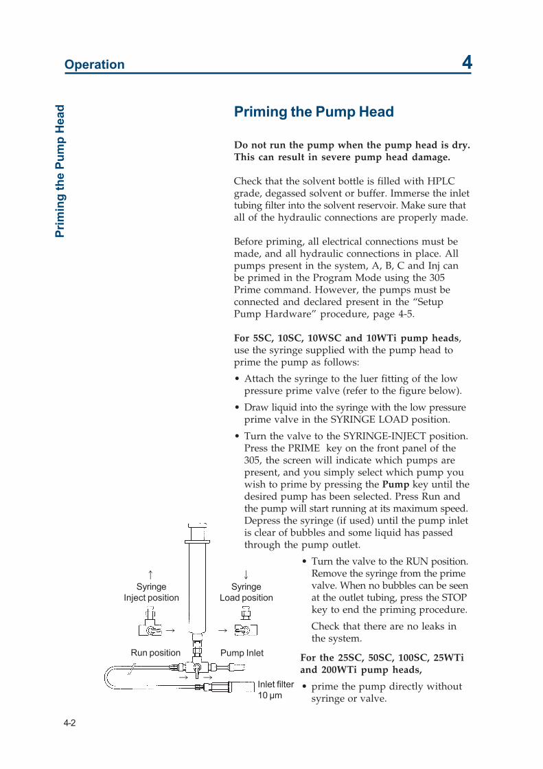
For 5SC, 10SC, 10WSC and 10WTi pump heads,use the syringe supplied with the pump head toprime the pump as follows:
• Attach the syringe to the luer fitting of the lowpressure prime valve (refer to the figure below).
• Draw liquid into the syringe with the low pressureprime valve in the SYRINGE LOAD position.
• Turn the valve to the SYRINGE-INJECT position.Press the PRIME key on the front panel of the305, the screen will indicate which pumps arepresent, and you simply select which pump youwish to prime by pressing the Pump key until thedesired pump has been selected. Press Run andthe pump will start running at its maximum speed.Depress the syringe (if used) until the pump inletis clear of bubbles and some liquid has passedthrough the pump outlet.
• Turn the valve to the RUN position.Remove the syringe from the primevalve. When no bubbles can be seenat the outlet tubing, press the STOPkey to end the priming procedure.
Check that there are no leaks inthe system.
For the 25SC, 50SC, 100SC, 25WTiand 200WTi pump heads,
• prime the pump directly withoutsyringe or valve.
SyringeInject position
SyringeLoad position
Pump Inlet
Inlet filter10 µm
Run position
� �
� �
� �

4-3
Operation 4Using the Keypad
Using the KeypadThe keypad consists of numeric keys, dedicatedkeys such as Enter and Prime, 5 white soft keys anda 2 line 24 character display. The function of eachpart of the keypad is as follows.
Numeric keys: Used to enter numeric values(todefine parameters).
PRIME: Runs the pump at maximum flowrate.
HELP: Displays help messages.CANCEL: Cancels a value before it is entered
into the memory.ENTER: Enter a value into the memory.
The 24-character display is used to indicate theflow rates, solvent compositions etc... The bottomline of the display is used to present the soft keyoptions above the 5 white soft keys. Pressing one ofthe white soft keys selects the option displayeddirectly above it. The following soft key options willoccur frequently and should be noted.
Quit: Return to the Ready-to-Run screen.Next: Brings you to the next screen.Prev: Brings you to the previous screen.
Time is expressed in minutes and hundredths of aminute. For example a time display of 2.50 min is 2minutes and 30 seconds.
The words “key in” mean enter in a numericalvalue. A flashing cursor on the screen underlinesthe current parameter to be entered/modified.
The symbol # is used in this guide to show thefactory set value (the default value).
The symbol • is used in this guide to show a keywhich must be pressed or a value which must beentered.

4-4
Operation 4
Setting Up the PumpThe software for the 305 Master pump can beexplained with the help of the chart in Figure 15.The chart has 4 software branches.
Pump: This is used to enter data about each pumpin the system, this means pumps A, B, Cand the Injection Pump, if present.
I/O: This is used to define the Input/Outputfunctions.
File: This is used to write a method program.Mode: This is used to select the mode of operation.
Setti
ng U
p th
e Pu
mp

4-5
Operation 4
With a new pumping system, you must enter dataabout each pump connected, i.e. Refill Time, solventCompressibility and pump Head Size and InletPressure. This is done using the Pump branch of thesoftware. Data concerning the overall pumpingsystem, for example high pressure limit, low pressurelimit etc. is done using the I/O branch of the software.The File branch is used for writing files of methodprograms. The Mode branch is used to operate thesystem in one of three possible modes, Flow,Dispense, or Program Mode.
The specifications for Pump and I/O must be set fora new system setup, or when the physical setup ofthe pumping system is changed, for example,changing a pump head size or removing or intro-ducing a pump.
Set Up Pump Hardware (PUMP)
A pumping system consists of a minimum of 1pump and a maximum of 3 elution pumps and1 injection pump. Pump A, the first elution pump(the 305 Master pump), is always present.
The sequence of screens and soft key commandoptions for the setup of pump hardware is shownin page 4-6.
To go to the pump setup menu:
• press Menu• press Pump
Use this menu to enter data about pump A.
• Select pump A by pressing the soft key below A• The sequence for defining parameters is:
1. Refill time2. Liquid Compressibility3. Head size4. Inlet Pressure (for liquefied gas)
A value for each parameter is keyed in using thekeypad and is stored in memory by pressingEnter. This automatically brings you to the nextmenu screen. If you do not want to change thevalue already stored in memory, press the Nextsoft key or press Enter.
Setting Up the Pump
The maximum flow ratedepends on the Head Size andthe refill time. If the refill timeis too long, a message Invalidsettings flashes when you runthe program. The refill time orflow rate must be lowered. Thefigure below shows a curve ofrefill times versus flow rate.

4-6
Operation 4
Pump A Refill time
The refill time is the time required for the pistonreturn stroke. Normally it is set at the lowest value(125 ms) to give the fastest refill time. If cavitationor degassing occurs, then a higher value must beused. The minimum value is 125 ms ( the defaultvalue) and the maximum value is 1000 ms.
# The default value is 125ms.• Key in the refill time and press Enter.
This brings the menu screen onto compressibility.
Setti
ng U
p th
e Pu
mp

4-7
Operation 4Setting Up the Pum
p
Pump A Compressibility
This data is used to calculate the flow rate compen-sation for the compressibility of the solvent. Theminimum value is 0 and the maximum value is2000 Mbar-1. Compressibility values for commonlyused solvents at atmospheric pressure are listed inAppendix E. The values for the most commonsolvents are:
# The default value is 46 for water.
• Key in the value for the solvent being used withpump A and press Enter.
Pump A Head Size
This parameter is the size of the pump head fittedto the pump. The pump head size is marked on theface of the pump head. Possible values are 5, 10,25, 50, 100 and 200.
# The default value is 200.
• Key in the value for the pump head size onpump A and press Enter.
The three parameters for pump A are now entered.
Press the Info soft key to display the operating timefor the pump head. This time can be reset to zeroby pressing the Reset soft key. This should be resetevery time the pump head has routine maintenanceor when a new pump head is installed. PressingOk returns to the pump head size display.
Press the Next soft key to return to the Setup pumphardware menu to setup the parameters for otherpumps in the system. Press the Quit soft key toreturn to the first Ready-to-Run screen. The nextmenu to program is the Input/Output parametersetup.
Inlet Pressure
The Inlet Pressure (P0) for liquefied gas is thepressure at the inlet of the pump head of the 305.For example, when using carbon dioxide at atemperature of 22°C, the value should be definedas 6 MPa. The minimum value is 0 for solvents usedin Liquid Chromatography and the maximumallowed value is 10 MPa. The default value is 0 MPa.
This menu will not appear ifthere is no manometric moduleconnected to the system.
Solvent X0 (Mbar-1)
Water 46Methanol 123Acetonitrile 99

4-8
Operation 4
A table of inlet pressure values for CO2 is shownbelow.
• Key in the desired inlet pressure according to theambient temperature.
• Press Enter.
The four parameters for pump A are now entered.
Entering the Parameters for Other Pumps inthe System
You must tell the 305 Master pump if the slavepumps B, C, and Inject are present in your system.By default, pumps B, C, and Inject are set aspresent. This can be changed by pressing theChange soft key when defining the relevant pump.
If a pump is defined as present, the parametersRefill Time, Compressibility and Head Size must bedefined.
If pump B is defined as absent, the Pump C isautomatically set as absent.
Summary:
• press the Menu soft key.• press the Pump soft key.• Select pump (A, B, C or Inj). (Define pumps B, C
or Inj as present or absent.)• Key in the desired refill time. (Minimum time 125
ms, maximum time 1000 ms.)• Key in the solvent compressibility. (Minimum
value 0, maximum value 2000 Mbar-1.)• Key in the relevant Pump Head Size. (5, 10, 25,
50, 100, or 200.)• Key in the Inlet Pressure. (Minimum value 0 MPa,
maximum value 10 MPa.)
When all pumps have been defined, press the Quitsoft key.
Ambient temperature (°C) 15 20 22 25 30 31 (TC)
Pressure P0 (MPa) 5.1 5.8 6.0 6.5 7.2 7.4 (PC)
Setti
ng U
p th
e Pu
mp
4-9
Operation 4
Input/Output Parameter Set Up (I/O)
The I/O menu is used to enter data about param-eters associated with the complete system. To go tothe Input/Output parameter setup procedure:
• press the Menu soft key• press the I/O soft key
The sequence for defining parameters is:
1. High pressure limit.2. Low pressure limit.3. Alarm On/Off.4. GSIOC ID number.5. Output Contacts.6. Pause/Program with or without flow.7. Gradient profile selection.8. Delay Volume selection.9. Zero Manometric Module.
The sequence of menu screens and soft key optionsis shown on page 4-6.
High Pressure Limit
If the pressure reading from the manometric mod-ule rises above the defined limit, the pump willstop. The sequence following a high pressure erroris described page 4-10.
The pressure can be displayed in three differentunits; bar, MPa, or kpsi. Change the units dis-played by pressing the soft key below the unitscurrently indicated on the display.
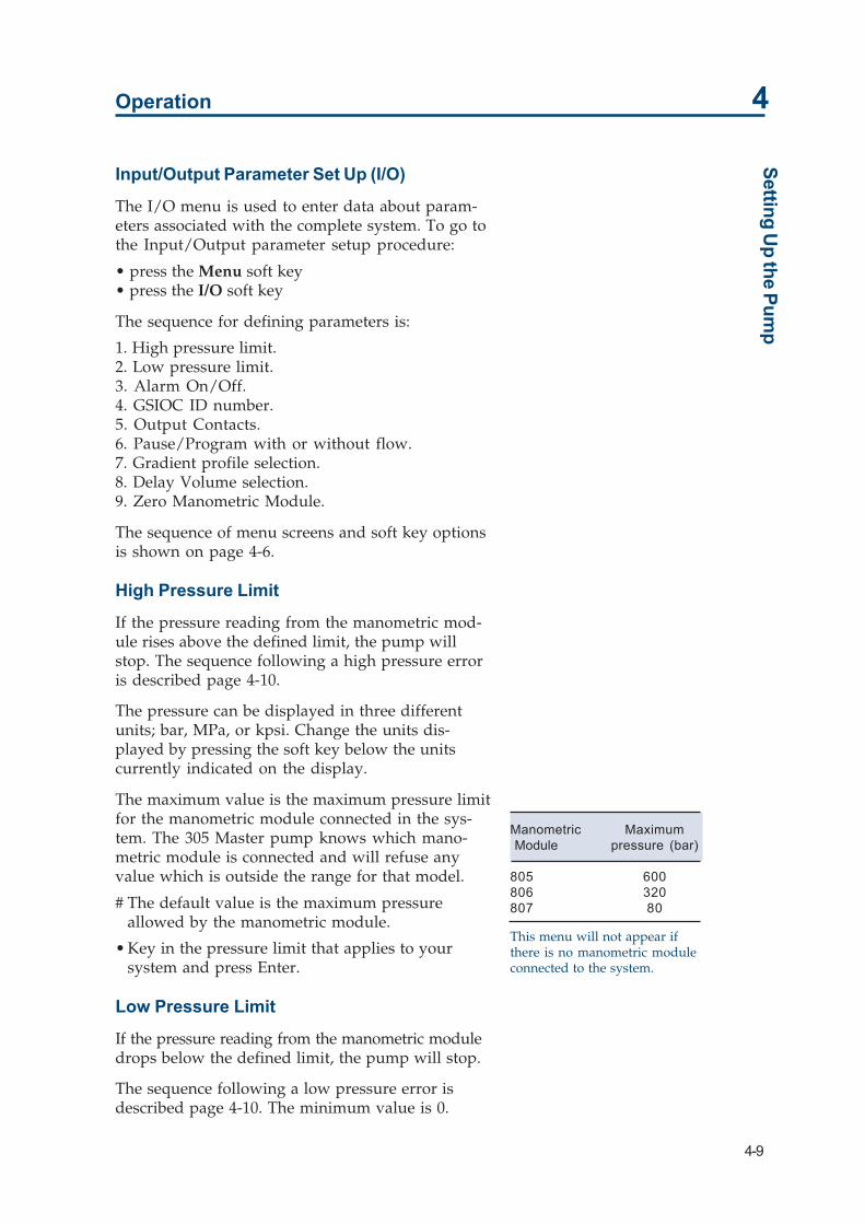
The maximum value is the maximum pressure limitfor the manometric module connected in the sys-tem. The 305 Master pump knows which mano-metric module is connected and will refuse anyvalue which is outside the range for that model.
# The default value is the maximum pressureallowed by the manometric module.
• Key in the pressure limit that applies to yoursystem and press Enter.
Low Pressure Limit
If the pressure reading from the manometric moduledrops below the defined limit, the pump will stop.
The sequence following a low pressure error isdescribed page 4-10. The minimum value is 0.
Setting Up the Pump
This menu will not appear ifthere is no manometric moduleconnected to the system.
Manometric Maximum Module pressure (bar)
805 600806 320807 80

4-10
Operation 4Se
tting
Up
the
Pum
p # The default value is 0.
• Key in the value that applies to your system andpress Enter.
This menu will not appear ifthere is no manometric moduleconnected to the system.
4-11
Operation 4
Alarm
The alarm is a buzzer which sounds every timethere is an error or an invalid setting entered orencountered. It can be programmed to be either Onor Off. This function only controls the operation ofthe buzzer, it does not affect the operation of thepump when there is an error.
If the alarm is set to be On, the warning buzzerwill sound every time an error is encountered. Anerror can be a pressure limit encountered, aninvalid setting, or a pump absent. This setting canbe changed from On to Off by pressing the soft keyunder Change.
# The default setting is Off.
• Select the option you want and press the Nextsoft key to go to the next menu.
GSIOC Unit ID Number
Each pump in a multipump system has to have anidentification number to distinguish it from otherpumps and equipment connected to the GSIOCcommunications channel.
When using a 305 Master pump, you must havethe identification numbers detailed in the tableabove for the slave pumps. The Master pump canhave any number between 0 and 63, however thedefault value of 1 is recommended for simplicity.
# The default value is 1.
• Key in the identity number you require for thispump and press Enter.
Output Contacts (Ouptut #xx is Open / Closed)
There are three relay outputs in the 305 Masterpump numbered 1, 2, and 3. These outputs can beused to control other instruments. They can beprogrammed to open and close during a methodrun. They can also be opened and closed manuallyusing soft key commands.
To change the state of an output, key in the numberof the output, for example output # 2. When youpress Enter, the display will show the present stateof output 2, i.e. Output # 2 open/closed. Press thesoft key Change to change the state of the output.
Do not set the Master pump IDnumber to 2, 3 or 4 as thesenumbers are reserved for theSlave Pumps and InjectionPump.
Setting Up the Pump

4-12
Operation 4
By using this procedure, each of the three outputscan be manually set to be open or closed. Theoutputs will remain in this state until a methodprogram is run and a change in the outputs isprogrammed.
# The default state is open.
• Press Next and go to the next menu.
Pause Prog With/Without Flow
This option runs in Program mode only. It enablesthe system to be controlled from an external sensor.For example, a temperature sensor can be used topause the system if the temperature is outside adesired range. The program and flow can bepaused together, or the program can be pausedwhilst the flow rate continues. External parameterssuch as temperature, pressure, or composition canbe monitored to control the system.
Gradient Profile
This function only operates in the program mode,and enables a selected gradient profile to be outputto a recorder from the analog output of the 305.The gradient profile can be selected as being asolvent composition, %B or %C or the flow rate(Flow). The solvent composition can be useful forbiochromatographic applications for plotting pHgradients and salinity (salt concentration) gradients.The flow rate can be useful for verifying detectorstability.
The analog output gives 1 V full scale. The full scalerepresents 100%B, 100%C or 100% of the maximumpossible (not programmed) flow rate of the system.This output is from connectors 12 and 13 on the I/Oconnector at the back of the 305. Pin 13 is the ground(0 V) connection.
Options are: Flow, %B, %C.
# The default setting is Flow.
• Press the Change soft key to select your desiredoutput and press Enter.
Setti
ng U
p th
e Pu
mp Setting the outputs manually is
useful to check that output # 1turns on the integrator forexample. However, whenrepeating the same operationmany times, it is better toprogram the output operationsas part of a method program. Inthis way, the outputs willfollow the same sequence eachtime the method program isrun. Refer to programming theoutputs in Section 3 of thisChapter.

4-13
Operation 4
Delay Volume
When the selected gradient profile is a solventcomposition (%B for instance), the Delay Volumecan be used to synchronise on the recorder the plotof the programmed profile with the plot of thedetected profile (baseline drift). In this case thedelay volume is generally defined, for a first ap-proximation, as being the total volume between themixer inlet and the detection cell inlet. The value isadjusted from experimental observation to obtainthe desired synchronisation.
The 305 software divides the Delay Volume by thetotal flow rate to calculate the total delay timeapplied to the analog output Gradient Profile. Thesize of the Delay Volume can be specified between0.01 mL and 999 mL.
# The default value is 0, i.e. no delay volume specified.
• Key in the required delay volume and press Enter.
Zero Manometric Module
The Zero soft key is used to set the manometricmodule value to zero when there is zero pressure inthe system. This ensures accurate pressure readingswhen the pumps are running. Before pressing theZero soft key, make sure that all pumps have stoppedand that the pressure has dropped to zero. Other-wise further pressure indications will be incorrect.This can be easily done by opening the prime/purgevalve whilst the pumps are not operating. If theoperation is successful the message Pressure read-ing is zero is displayed. If the operation is notsuccessful, the message Not done - check pressurereadings is displayed.
You have now completed the Input/Output pa-rameter setup. Press Quit to leave this branch ofthe software. This will bring you back to one of theReady-to-Run screens.
Summary:
• Press the Menu soft key.• Press the I/O soft key.• Set the High Pressure Limit (Maximum value
depends on Manometric Module).• Set the Low Pressure Limit.• Set the Alarm to be On or Off.
Setting Up the Pump
The Delay Volume option willonly appear if %B or %C hasbeen selected for GradientProfile.

4-14
Operation 4
• Set the GSIOC ID number for the 305 Master pump.• Program outputs to be Open/Closed.• Set pause in program to be with or without flow .• Select the Gradient profile output to be Flow, %B,
or %C.• Specify the Delay Volume. (Maximum value 999 mL)• Zero the Manometric Module.• When all I/O functions have been defined as
required, press the Quit soft key.Setti
ng U
p th
e Pu
mp
After entering the data about the pumping system, thepump is ready to run. The 305 Master pump canoperate in three different modes. These modes are:
Flow: The 305 pump provides a constant flow rate. Thepump starts when the Run key is pressed and stopswhen the Stop key is pressed. The flow mode is forisocratic use only.
Dispense: The 305 dispenses a specified volume. Thepump starts when the Start key is pressed and stopswhen the specified volume has been dispensed. Thedispense mode is for isocratic use only.
Program: The 305 controls a multi-pump system withup to 2 slave elution pumps and 1 slave injectionpump. In this mode, the 305 Master pump can creategradients of flow rate and composition, open and closeoutputs to control other instruments and wait forsignals from other instruments.
The operation of each mode is explained.

4-15
Operation 4M
ode Selection
Mode Selection
Running the Pump in Flow Mode
In Flow mode, the pump provides a constant flowrate, commencing when the Run soft key or startinput is activated. The pump stops when the Stopsoft key or stop input is activated.
To go to the Flow mode:
• press the Menu soft key.• press the Mode soft key.• press the Flow soft key.
This brings you to the Flowmode Ready-to-Run screen.The sequence of screens andsoft key command optionsfor using the flow mode canbe seen in the oppositefigure.
The flow rate can be setbetween 0.01% and 100% ofthe pump head size fitted tothe 305 Master pump. Aflow rate value will not beaccepted if it is larger thanthe pump head size. If theselected flow rate is incom-patible with the refill time orcompressibility, the messageInvalid settings flashes afterpressing run. In this case,you must reduce the refilltime or the flow rate.
• Key in the flow rate inmL/min and press Enter.
• You can change the pres-sure units displayed at anytime by pressing the softkey under the pressureunits currently displayed(in this example the unitsdisplayed are in bar).

4-16
Operation 4
• The pump will start either when the Run soft keyis pressed, or when the start input is activated.
• The pump will stop when the Stop soft key ispressed, or when the stop input is activated.
Modifying the Flow Rate
The flow rate can be modified at any time during arun by keying in a new value. It is possible toreview and change the pump and I/O setup pa-rameters except the pump head size during a run.Press the Menu soft key and follow the setupprocedures described pages 4-10 to 4-15.
Operation of the Pressure Limits in the FlowMode
The maximum pressure limit depends on thedefined Refill Time and Compressibility. If theparameters defined in the I/O setup procedure arenot compatible with the flow rate entered, themessage Invalid settings will flash on the screenafter the Run soft key is pressed, or the start inputactivated. In this case you must lower the refill timeor the flow rate.
If there is a high pressure error, the pump will stopand the message High pressure limit will flash onthe screen. The alarm will sound if it is pro-grammed to be on. The pump will start again whenthe pressure drops below the defined limit. Thiscycle will continue indefinitely.
If there is a low pressure error, the pump will stopand the message Low pressure limit will flash onthe screen. The alarm will sound if it is pro-grammed to be on. The pump will stay in thiscondition until the Stop soft key is pressed.
The flow mode can be simulated in the Programmode, with the advantage of having safety errorfiles and having the option of including timedevents.
Mod
e Sel
ectio
n

4-17
Operation 4M
ode Selection
Running the Pump in Dispense Mode
In this mode the pump can be used to deliver aspecified volume beginning when the Run soft keyor start input is activated, and finishing when thespecified volume of liquid has been delivered. Theparameters to enter are dispense volume anddispense flow rate or time of dispense.
To go to the dispense mode :
• press the Menu soft key.
• press the Mode soft key.
This brings you to the Dispense mode Ready-toRun screen. The sequence of screens and soft keycommand options for using the flow mode can beseen in the Figure on the next page.
Two parameters are displayed on the top line of thescreen, the dispense volume, and the dispense time.A flashing cursor appears under the dispensevolume setting, key in the required dispense volumeand press Enter. The flashing cursor now moves tothe dispense time display, key in the dispensingtime and press Enter. If you wish to define thedispense volume and dispense flow rate instead,press the Rate soft key. The top line will thenchange to display the dispense volume and flowrate.
• Key in the dispense volume and press Enter.
• Key in the dispense time (or rate) and press Enter.
The limits for each of the parameters are as follows:
Maximum dispense volume:100 x head size (mL).
Minimum dispense volume:0.0001 x head size (mL).
Maximum dispense flow rate:1 x head size (mL/min).
Minimum dispense flow rate:0.0001 x head size (mL/min).
Maximum dispense time:9999 minutes.

4-18
Operation 4
The maximum dispense flow rate depends on theRefill Time and Compressibility. If the parametersare not compatible with the dispense flow rate orvolume entered, the message Invalid settings willflash on the screen after the Run soft key is pressed.In this case you must reduce the refill time or theflow rate.
If the dispense flow rate or volume is not compat-ible with the head size, the software will not acceptthe value and you must key in a new value. If thehead size is changed to a size that is too small afterthe dispense volume and flow rate have beenentered, the Run soft key will not appear in themenu when you return to the dispense Ready-to-Run screen.
• press the Run soft key to start the delivery of theliquid. The delivery will stop when the specifiedvolume has been delivered.After pressing the Run soft key, the displaychanges to give Roll-Pause options for the softkeys.
• press the Paus soft key to interrupt the dispenseoperation. The display changes to give End-Continue options.
• press the End soft key to terminate the deliverywithout dispensing any more liquid.
• press the Cont soft key to continue delivering thespecified volume.
• press the Roll soft key to review the programmeddispense volume and the volume already dispensed.
• press the Roll soft key again to view the pro-grammed time for the dispense and the timealready elapsed.
• press the Roll soft key again to review the flowrate.
Modifying the Values
It is not possible to change the dispense volume ordelivery rate during a run. All of the setup param-eters (including I/O parameters) except the headsize can be reviewed and modified during a run.Press the Menu soft key and follow the setupprocedures as described in pages 4-10 and 4-15.
Mod
e Sel
ectio
n

4-19
Operation 4
Operation of the Pressure Limits
As a safety feature of the system, it is possible todefine high pressure and low pressure limits so thatthe operation will stop when the system pressurefalls outside these limits.
If the high pressure limit is exceeded, for whateverreason (column clogged, wrong valve closed etc.),the pump will stop and the message High pressurelimit will flash on the screen. The alarm will soundif it is programmed to be on. The pump will startagain when the pressure drops below the limit.This cycle will continue indefinitely.
Mode Selection

4-20
Operation 4
If the pressure falls below the low pressure limit,the pump will stop and the message Low pressurelimit will flash on the screen. The alarm will soundif it is programmed to be on. The pump will stay inthis condition until the End soft key is pressed.
The dispense mode can be simulated in the Programmode with the added advantage of having SafetyFiles (described page 4-31), and being able to programtimed events.
Running the Pump in Program Mode
In this mode, the 305 Master pump can create bothflow rate and composition gradients, program timedevents, and control an injection pump. The programmode can also simulate the flow and dispense modes,with the advantage of safety error files and theability to program timed events. The sequence ofscreens and soft key command options for program-ming the flow mode can be seen in Figure below.
Mod
e Sel
ectio
n

4-21
Operation 4
At the end of a run in Program mode, the SolventConsumption can be obtained by selecting theappropriate roll screen.
The 305 controls up to two other elution pumpsand one injection pump through the GSIOC cable.Other instruments such as auto-samplers andfraction collectors can be connected to the 305Master pump using the Input/Output contacts onthe rear panel of the 305.
Before creating a method program in the 305Master pump, it is necessary to understand howthe method programs are stored in memory.
Memory Layout
There are 14 files, numbered 1 to 14. Each file canstore 1 program. Files 1 to 10 are user files, avail-able for method programs. Files 11 to 14 are re-served for safety/error programs.
A file contains timed events. A timed event is aflow rate, a solvent composition, the operation ofan input or output or the operation of an injectionpump. One file stores a maximum of 25 timedevents which can make up the method program.
The Safety Files, 11 to 14, do not contain pre-storedprograms you can write each Safety File accordingto your own requirements, for example, to output acontrol signal to an external device. Write eachsafety program in the same way as a methodprogram. This allows you to program the sequenceof events that will happen when an error occurs. Ifan error occurs during a run, the method programstops and the relevant safety program starts. If nosafety program has been written, the default opera-tion in the event of an error is described in eachrelevant Safety File description. See pages 4-31 to4-33 for the exact operation of Safety Files.
Mode Selection

4-22
Operation 4
File SelectionOne complete method is stored in a file. In order toread/edit/write a method, you have to go to a file.The sequence of screens and soft key commandoptions for programming a file can be seen in thefigure below.
File
Sel
ectio
n
To go to a file:
• press the Menu soft key.
• press the File soft key. This brings you to theSelect file menu.
Key in the number of the file, for example 1, andpress Enter.
There are five soft key options available:
• Directory
• Copy
• Delete
• Edit/New
• Quit

4-23
Operation 4
Directory
Press this key to go to each stored file, e.g. File 1,File 3 etc. This displays all of the files where methodprograms are stored. If no programs are stored, asin the case of a new pump, Select file # —will bedisplayed. Key in the file number that you want touse and press Enter.
Copy
Press this key to make a copy of a complete file.This is useful if you want to make a small modifica-tion to an existing program and keep a copy of theoriginal program. After pressing copy, key in thefile number where the copy will be stored and pressEnter. The software indicates if the file where youwant to store the copy is empty (New) or if there isa program already stored there (Exists). You havethe choice of completing the copy procedure, Yes,or ending the procedure without making a copy,No. The copy of the program can then be modifiedwithout destroying the original.
Delete
Press this key to delete a complete file. The deletedfile is the file currently shown on the upper line ofthe display. After pressing Del, Delete file # xx ?is displayed. This is a safeguard against accidentalerasure. There are two options: Yes deletes the file,No brings you back to the original menu.
Edit/New
If there is no program stored in the file number thatis displayed on the top line, the display will be New,if there is a program stored in the file, the displaywill be Edit. Both of these options will bring you tothe first step in writing/editing a method program.
Quit
Pressing Quit brings you back to the Ready-to-RunScreens.
Pressing the Edit/New key brings you to the first menuin the programming sequence, Number of loops.You are now ready to write a method program.
File Selection

4-24
Operation 4
Programming a MethodA complete method program is written by pro-gramming flow rates, solvent compositions andoperation of the outputs. The method program runtime starts at time 0.00, i.e. when the start key ispressed, and ends at the time of the last timedevent. For example, if you program the last event attime 20.00, then the run time is 20 minutes.
You must program every event for your method,starting at time 0.00. For example, at time 0.00 youmust program the flow rate and composition. Ifyou do not program anything at 0.00 minutes, thepump will assume the current flow rate and com-position. For a pump which is stopped, the soft-ware will assume a flow rate of 0 mL/min and acomposition of 100% A, 0% B, and 0% C. If thepump is running, it will assume the current flowrate and composition for time 0.00. It will thenoperate on a gradient between these values and thefirst flow rate in your program and the first solventcomposition in your program.
Menu: Number of Loops
The number of loops is the number of times that theprogram will repeat itself before stopping. Theminimum value is 1 and the maximum value is 999.
# The default value is 1.
• Key in the number of loops and press Enter.
This brings you to the When finished, use menu.
Menu: When Finished, Use
At the end of a program, you can link the currentfile to any of the 14 files. If you do not want to linkto any other file, press the soft key below None onthe display.
If you link to the current file, i.e. link File 3 to File 3,the program will continue to run until the Pausekey is pressed. If both looping and linking areprogrammed, the software will complete the pro-grammed number of loops, then link to the newfile.
Prog
ram
min
g a
Met
hod

4-25
Operation 4Program
ming a M
ethod
If you link files together which have differentvalues for the setup parameters, the pump will notstart. After pressing Run the display will give youthe message Note ! Setup has changed since filecreation. Pressing Ok gives you the choice of whichsetup parameters to keep by asking the questionKeep original setup ? Yes - No. If you choose Yes,the values which are stored in the first file in thesequence of files will be loaded into all of the fileswhich are linked together. If you choose No, thevalues which are currently stored in the pumpssetup parameter memory will be loaded into all ofthe files which are linked together.
# The default value is None.
• Key in the number of the file you want to link toand press Enter, or press the None soft key.
This brings you to the Choose an event type screen.
Menu: Choose an Event Type
There are five different types of timed events. Youchoose one of the different events by pressing thesoft key below it. The five timed event types are:
• MixtureProgram the composition, %A, %B and %C.
• FlowrateProgram the flow rate, mL/minute.
• WaitWait for an input.
• OutActivate an output.
• InjectActivate the injection pump.
At the end of each operation, the solvent consump-tion will be displayed.
Mixt
Set the composition of the solvents, e.g. 70 % solventA, 20 % solvent B and 10 % solvent C. There is amaximum of three pieces of data for this menu:
- Time at which composition occurs
- % of solvent B
- % of solvent C.
One complete method programis stored in a file. The values forthe six parameters; Refill Time,Compressibility, Pump HeadSize, Inlet Pressure, HighPressure Limit and Low PressureLimit for that method programare also stored in the same file.If you link two or more filestogether, you must ensure thatthey all have the same valuesfor these parameters.
In the case of linking an errorfile which has different setupparameters to the method file,the parameters for the methodfile automatically replace thevalues which were written inthe error file.

4-26
Operation 4
The percentage of solvent A is calculated as:% solvent A = 100 - % B - %C.
The example opposite is for a binary gradient.At 0 minutes, there is 95% solvent A and 5%solvent B. At 5 minutes, there is 80% solvent Aand 20% solvent B.
Example: 0.00 min 5%B (%A = 95%)5.00 min 20%B (%A = 80%)
To program the example:
• press the Mixt soft key.
• key in the time for the first composition point,0.00, and press Enter.
• key in the value for the %B, 5, and press Enter.
• press the Add soft key to add a second timedevent to the program.
• key in the time for the second composition point,5.00, and press Enter.
• key in the value for the %B, 20, and press Enter.
Composition parameters can be set down to 0.1%increments. If you key in a value which is too high(sum A+B+C>100%) the last entry will not beaccepted by the software and you must key in thelast value again, or correct your composition speci-fication.
Flow
In this menu, you can set the flow rate, for example,2 mL/min. There are two parameters to specify forthis menu.
- Time at which flow rate occurs.
- Flow rate in mL/min.
Example: 0.00 min 0.00 mL/min5.00 min 3.0 mL/min
To program this example:
• press the Add soft key.
• press the Flow soft key.
• key in the time for the first flow rate, 0.00, andpress Enter.
Prog
ram
min
g a
Met
hod
There will be a linear gradientbetween two solvent composi-tion points. With the examplegiven, the %B will increaselinearly from 5% to 20% in 5minutes. If you change thegradient point during a run, thenew gradient will be betweenthe next programmed gradientvalue and the value whichexisted at the instant thegradient was modified.
If you do not program acomposition at 0.00 min., thepump assumes the currentcomposition. For a stoppedpump, this will be 100% A.There will then be a gradientbetween 100% A and the firstprogrammed solvent composi-tion point. Programming theexample above will give acomposition gradient as shownin Figure.

4-27
Operation 4
• key in the value for the flow rate, 0, and pressEnter.
• press the Add soft key to add a second timedevent.
• key in the time for the second flow rate, 5, andpress Enter.
• key in the second flow rate, 3, and press Enter.
If you try to enter a flow rate value which is toohigh for the pump head, the entry is refused by thesoftware. The maximum value accepted in a gradi-ent system is the value of the smallest pump headsize in the system.
If you do not program a flow rate at 0.00 min., thesoftware will assume the current flow rate for thetime 0.00 min., i.e. for a stopped pump, a flow rateof 0 mL/min. There will then be a gradient be-tween 0 mL/min. and the first programmed flowrate. With this example the flow rate will be asshown in the opposite figure.
To stop the flow of solvent at the end of a run,you must program a flow rate of 0 mL/min. Other-wise, the pump will continue to run with the lastprogrammed flowrate, even after the last timedevent. If there is more than one pump in the system,you must program a composition point containingall of the pumps followed by a flow rate of0 mL/min.
If the system is set up to do more than onesample, the initial composition for themethod can be maintained between methodruns by programming this composition atthe end of the program, for example 5% B.At the end of all the samples, link to an-other file to completely stop the flow ofliquid. See the opposite figure.
Wait
In this menu you can make the program wait untilInput # 1 is activated. This is used to stop theprogram until another piece of equipment is ready,for example an auto-sampler or a fraction collector.There are two pieces of data for this menu.
Programm
ing a Method
There will be a linear gradientbetween any two programmedflow rates. With the aboveexample, the flow rate willlinearly increase from 0.00 mL/min to 3.0 mL/min in 5.00minutes.

4-28
Operation 4
- Time at which the pump will wait for an input
- Waiting for an open contact or a closed contact
Example 4: 2.00 min Wait #1 Closed.
To program this example:
• press the Add soft key.
• press the Wait soft key.
• key in the time for the wait to begin, 2.00, andpress Enter.
• press the close soft key.
The program waits at time 2.00 minutes until input#1 is closed. If input #1 is already closed at time2.00 mins, the program will continue. If input # 1 isnot closed, the program will wait. During the timethat the program is waiting, the display will showthe total run time and the time that it has beenwaiting.
If a pump is waiting for an input, pressing Cancelwill simulate an input and the program will con-tinue.
Out
In this menu, you can program each of the outputsin the system to open or close. The out-puts arenumbered 1, 2 and 3 and are used to send signalsto other equipment in the system, for example anauto sampler or a chart recorder. By having theoutput operations as part of the method program,the same sequence of contacts repeats every timethe method program is run.
There are three pieces of data for this menu.
- Time at which output is operated
- Output number
- Output opened, closed or pulsed
Each of the outputs can be made to open, close orpulse. Pulse means that the output will change itscurrent state for 0.6 of a second.
Prog
ram
min
g a
Met
hod

4-29
Operation 4
Example: Screen 1 3.00 min Output 2Screen 2 Open Close Pulse
To program this example:
• press the Add soft key.
• press the Out soft key.
• key in the time for the output to operate, 3.00,and press Enter.
• key in the output number, 2, and press Enter.
The display will change to Open, Close or Pulse.
• press the Close soft key.
Inj
In this menu you can injection a sample using theinject pump. There are three pieces of data for thismenu.
- Time at which the injection pump is started
- Injection volume
- Flowrate for the injection
Example: Screen 1 2.00 min Inj 6.00 mLScreen 2 Inj rate 0.5 mL/min
To program this example:
• press the Add soft key.
• press the Inj soft key.
• key in the time at which the injection will start,2.00, and press Enter.
• key in the injection volume, 6.00, and press Enter.
• key in the value for the injection rate, 0.5, andpress Enter.
The injection rate parameter can be changed toinjection time by pressing the Time soft key. Thereis a limit of one injection point for each methodprogram. The maximum injection volume is thepump head volume multiplied by 100. If you programa second injection point, it will write over theexisting injection point.
Preparative injection: The 305 can be used in theProgram mode for repetitive injection of the samesample.
Programm
ing a Method

4-30
Operation 4
At the selected time, the Master 305 starts theinjection pump and automatically lowers theelution rate in order to keep the total flow rate, andhence the pressure, constant. The following rela-tionship is applied:
F’e = Fe - Fi whereF’e : the total elution flow rate during injectionFe : the total elution flow rate before injectionFi : the injection flow rate
A stop-flow injection, generally desired, is thenobtained by selecting Fi � Fe.
Reading/Writing/Editing Timed Events
The five different types of timed event have beenexplained above. At the end of each event, themenu gives you five options. These options areexplained below.
Next: displays the next timed event in the se-quence. If there are no more events, it dis-plays End of file.
Prev: displays the previous timed event in thesequence. If there are no more previousevents, it displays Beginning of file.
Add: brings you to the Choose an event typemenu to allow you to add another event tothe present program.
Del: deletes one timed event in the program. Asa safeguard it asks you, Delete this point ?Press Yes to delete the event or No to returnto the original menu.
End: leaves the software for programming timedevents. The pump displays Solvent con-sumption in mL for pump A for one com-plete run of the method program.
Pressing the Next soft key displays in turn theconsumption for the other pumps in the system.The minimum consumption is < 0.1 mL. The maxi-mum is > 999 mL.
Press Quit to go to the Ready-to-Run Screen. Youhave now finished creating a program method file.Before running a method program, you shouldprogram each of the four safety/error files.
Prog
ram
min
g a
Met
hod

4-31
Operation 4
Programming the Safety FilesThe Safety Files are a useful safety feature whichcan be used to control the pumping system if a mal-function is detected. It is possible to detect if thesystem pressure is too high or toolow, if there has been a powerfailure, or if an external sensor hasdetected an illegal value (tempera-ture too high, for example). In thiscase, the method program isstopped, and the relevant Safety Fileis run. The File number and functionof each File is listed in this table.
These programs are created in exactly the sameway as a method program. To program the lowpressure safety file, select file 11 and enter thesequence of flow rates and input/output operationsthat you require when there is a low pressure error.Similarly, enter a program for the high pressuresafety file, Input# 2 safety file and the powerfailure safety file. The Input # 2 contact can beconnected to an external safety device such as atemperature or pressure measurement system.
An example of simple programs for the high andlow pressure safety files are given in program lists 2and 3 at the end of this section.
Low Pressure Safety File (File 11)
If the pressure goes below the low pressure limitthe sequence of events is as follows:
• If the low pressure error file (11) contains noprogram, the method program will stop and cannot resume until the operator presses the Pausesoft key followed by End.
• If the low pressure error file contains a program,the method program will link to this file and willrun it. After file 11 is finished, if there is a link toanother file, this new file will start to run. If thereis another low pressure error during file 11, thepump will stop and can not resume until theoperator presses the Pause soft key followed byEnd.
For an example of a Low Pressure safety file refer topage 4-39, Program List 2.
Programm
ing the Safety Files
File Name Function
11 Low File runs after a low pressure error12 High File runs after a high pressure error13 Input File runs if input # 2 is activated14 Power File runs after a power failure

4-32
Operation 4
High Pressure Safety File (File 12)
If the pressure goes above the high pressure limit,the sequence of events is as follows:
• If the high pressure safety file (12) contains noprogram, the pumps stop at the instant the pres-sure rises above the limit. If the pressure dropsbelow the limit again, the pump will restart. Thiscycle will continue indefinitely.
• If the high pressure safety file contains a pro-gram, the pumps stop and wait for the pressureto drop below the high pressure limit containedin File 12. When the pressure is below this limit,file 12 will begin to run. After file 12 is finished, ifthere is a link to another file, this new file willstart to run. If there is another high pressure errorduring file 12, the pump will stop until the pres-sure drops below the limit and will then restart.This cycle will continue indefinitely.
For an example of a High Pressure safety file, refer topage 4-39, Program List 3.
Input # 2 Safety File (File 13)
When input # 2 is activated, it causes the followingsequence of events:
• If there is no program in File 13, activating input# 2 will have no effect and the method programwill continue.
• If there is a program stored in File 13, when input# 2 is activated, File 13 will start. File 13 will startto run even if the system was not previouslyrunning. If there is a link to another file at the endof the program, the linked file will start to run.
Power Failure Safety File (File 14)
The power failure safety file will only operate ifthere is a power failure while a method program isrunning. The sequence of events after a powerfailure is as follows:
• If there is no program stored in File 14: after thepower is restored, the program will go back to thestart of the method file and wait for a start input.
Prog
ram
min
g th
e Sa
fety
File
s

4-33
Operation 4
If there is more than one file in the method, i.e.one file is linked to another, the program will goback to the beginning of the first file in themethod.
• If there is a program stored in File 14: after thepower is restored, the program in file 14 will berun. If there is a link to another program at theend of file 14, the linked file will start to run. Ifthe alarm is on, it will sound.
If there is a power failure in the Flow or Dispensemodes, it has the same effect as if the pump wasturned off and turned on again. The screen pre-sented will be the Ready-to-Run Screen of the lastused mode.
Programm
ing the Safety Files

4-34
Operation 4
Running a Method ProgramAt the end of programming the method and errorfiles, the software returns to a Ready-to-RunScreen. The top left corner will indicate whichReady-to-Run screen you are in. To go to theProgram mode Ready-to-Run Screen:
• press Menu.
• press Mode.
• press Prog.
The pressure can be displayed in 3 units, bar, MPaor kpsi. To change from one unit to another, pressthe soft key directly below bar. The units willchange to MPa. Pressing the soft key again willchange the units to kpsi. Pressing the soft key againwill change the units back to bar.
You can go to any file by keying in a new numberand pressing Enter. The Ready-to-Run Screendisplays the present file number, the pressure, andgives you 3 soft key options, Cond, Menu and Run.
Cond Soft Key
It brings you to the part of the software which isused to condition the column. You program a ramptime, the flow rate and gradient. The initial condi-tions are the existing conditions for the pump, i.e. fora pump which is not running 0 mL/min and 100%solvent A. The flow rate and composition program-med should be the flow rate and composition thatis required at the start of the method program thatyou are going to use. The solvent flow rate andcomposition are then ramped from 0 mL/min and100% A to the initial composition and flow rate foryour method program.
• press Cond.
• enter the ramping time and press Enter.
• press Flow.
• enter the flow rate for the end of the ramp time.
• enter the % B for the end of the ramp time (ifpump B is present).
• enter the % C for the end of the ramp time (ifpump C is present).
Runn
ing
a M
etho
d Pr
ogra
m

4-35
Operation 4
Press Run to start the conditioning of the column.The pump will ramp to the flow rate and solventcomposition that is programmed in the time pro-grammed. The values for time, flow rate andsolvent composition can be changed during theconditioning. At the end of the ramp time, the flowrate and solvent composition will remain constant.Note that you can leave the conditioning of thecolumn and create a program without interferingwith the conditioning of the column.
After pressing Run, the display changes to give youthe choice of Roll, Stop or Quit.
Pressing Roll displays in turn the time for the ramp,the flow rate, the proportion of solvent A, B and Cin turn. The proportion of solvents B and C will notappear if they do not exist.
This part of the software is also used at the end of amethod program to clean the column. The initialconditions will be the final flow rate and composi-tion which existed at the end of your methodprogram. You can ramp the flow rate down to 0mL/min and create a solvent gradient that willcompletely clean the column.
The Quit soft key brings you to the Select MenuItem menu. This gives you access to the pumpsetup parameters, the pump I/O parameters andthe method file. Press this key to verify or changethe value of any parameters in these sections.
Run Soft Key
It starts the program running. When this key ispressed, the display changes. The figure in the topleft hand corner is the file number. The number inparentheses is the loop number. If there is more thanone loop in your program, the present loop numberwill be displayed here. The first time displayed isthe actual running time. The second time displayedis the total running time for the method program.
When a program is written, the current values forthe six parameters Pump Head Size, Compressibility,Refill time, Inlet Pressure, High Pressure Limit andLow Pressure Limit are stored as part of themethod program.
Running a Method Program

4-36
Operation 4
When the file is being run again, if any of theseparameters has been changed, the following mes-sage will appear after Run has been pressed, Note!Setup has changed since file creation Ok. PressOk. You can choose to keep the setup parameterswhich were stored with the method program oryou can choose to keep the setup parameters whichexist currently. Press Yes to keep the setup param-eters which existed when the file was created. PressNo to keep the current setup parameters. Afterpressing one of these keys the pump will automati-cally start running the file.
If a program has a link to a file which has nothingstored in it, the program will not start when Run ispressed. The message Link file does not exist isdisplayed and the alarm will sound.
After pressing Run, the bottom line of the displaychanges to Roll/Menu/Pause.
• Pressing Roll will display in turn:- current file/loop number/running time and
program time- current file/loop number/current flow rate- the % of solvent A- the % of solvent B- the % of solvent C- the time that the 305 is waiting on an input- the programmed injection volumePressing Roll once more brings you back to theRun screen.
• The Menu soft key has the same function asbefore.
• Press Pause to freeze the program. The pumpswill continue to run, keeping a constant flow rateand composition. The pumps will stay in thisstate until another key is pressed. When Pause ispressed the screen changes to Stop/End/Cont.- Stop will cause the pumps to stop. The method
file remains in the Pause state.- End will cause the termination of the method
file without stopping the pumps. The pumpswill continue with the flow rate that existedwhen the pumps were paused. The screenreturns to the Program mode Ready-to-RunScreen.
- Cont will cause the program to continue fromthe point where it was paused.
Runn
ing
a M
etho
d Pr
ogra
m
The input Start/Stop has thesame effect as the End soft keyin the Program mode.
To terminate a programcompletely and stop the flow,you must press Stop followedby End. If a method programhas terminated and the pump-ing system is still running,press Cond followed by Stop.

4-37
Operation 4
During a method run, the setup parameters andthe method program can be modified. Modify aparameter in the same way that you program it. Ifthe flow rate or composition is modified during arun, the new value will take effect from theinstant it is programmed. If a flow rate is modifiedwhile the pump is running, the new flow gradientwill be between the next programmed point andthe flow rate which existed at the instant themodification was made.
After a method program has finished, the displayreturns to the Ready-to-Run screen.
Running a Method Program

4-38
Operation 4Pr
ogra
mm
ing
Exam
ples Programming Examples
Two example programs are given below. Beforerunning these example programs, ensure that thehydraulic circuit is properly connected.
Example 1
In the example given in List 1, the flow rate willstart at 1 mL/min and increase to 4 mL/min after2 minutes. The composition will be constant at100% solvent A. An output will close at 0.00 min-utes to start the integrator. The method will onlyoperate once and will not link to another file whenit is finished. Enter this program following the stepsgiven Program list 1.
Note that it is necessary to program a flow rate of0 mL/min at the end of the program to stop theflow, the flow does not automatically stop whenthe program is finished. It will continue with thelast programmed flow rate. To stop the flow at 4.00minutes you must program a flow rate of 4 mL/minat 3.99 minutes and 0.00 mL/min. at 4.00 minutes.
Note on Programming Sheet
Appendix G contains a programming sheet whichcan be copied. An example of how to use theprogramming sheet is also given. The sequence youshould follow is:
• Fill in the File Number and name
• Fill in the SETUP parameters for your system
• Draw the flow rate and composition gradients onthe graphs provided, remembering to mark theaxes
• Fill in the table for Input/Output operations
• Write the programming steps. Finish one sectionbefore going on to the next, i.e. program all of theflow rate time points before going on to thecomposition time points. The 305 software willarrange all of the time points in the correct sequence.
After writing the method program, it is necessaryto write the programs for the safety/error files.

4-39
Operation 4
Simple programs are given in list two and three forthe Low pressure error file and the High pressureerror file. In both programs, the flow rate is pro-grammed to be 0 mL/min. This is a simple exampleof an error file.
Enter these two error programs before run-ning Example 1. After entering the twopressure error programs, the system is readyto run. Press Run. The display will look asopposite. Press Roll to display in turn theflow rate, %A, %B, %C, return to the runscreen. When the method program is fin-ished, the Ready-to-Run screen is displayed.
Programm
ing Examples
Program List 1
Key to press Notes
MenuFile1/ENTER Select file 1New/Edit Go to file1/ ENTER 1 LoopNone No link at end of methodOut Program the output0/ ENTER At 0.00 minutes1/ENTER Output # 1Close Close output # 1Add Add the next timed eventFlow Enter the flow rate0/ENTER At 0.00 minutes1/ENTER Flowrate = 1mL/min.Add Add the next timed event.Flow Enter the flow rate2/ENTER At 2.00 minutes.4/ENTER Flowrate = 4mL/minEnd Finish writing method
Solvent A consumption: 5mLQuit Go to Ready-to-Run screen
Program List 2
Key to press Notes
MenuFile11/ENTER Low pressure safety fileNew/Edit Go to file1/ENTER 1 LoopNone No link to other filesFlow/ENTER Enter the flow rate0/ENTER At 0.00 minutes0/ENTER Flow rate = 0mL/minEnd Finish writing safety fileQuit
Program List 3
Key to press Notes
MenuFile12/ENTER High pressure safety fileNew/Edit Go to file1/ENTER 1 LoopNone No link to other filesFlow/ENTER Enter the flow rate0/ENTER At 0.00 minutes0/ENTER Flow rate = 0 mL/minEnd Finish writing safety fileQuit

4-40
Operation 4
Example 2
The operation of the method in Example 2will be as follows.
File # 4 contains the method program. Theflow rate remains constant throughout theprogram. At 0.00 minutes the mobile phasewill have a constant flow rate of 3 mL/minand a composition of 95% A, 5% B and 0%C. The composition will change to 70% A,30% B and 0% C in a time of 1 minute. Thecomposition will stay constant for 1minute and then return to 95% A, 5% Band 0% C in a time of 0.5 minutes. Thecomposition will remain at 5% B until 4.00minutes. The program will loop and repeatthe same method 3 times and will thenlink to File 5.
File 5 will contain a program to set the flow rate to0 mL/min. The Low pressure and High pressuresafety files that were used in the first example canalso be used for this example. It is not necessary toreprogram them.
Enter this program by following the steps given inProgram list 4 and 5.
The system is now ready to run. PressRun.The display will look as opposite.Press Roll to see the % of A and B changing.After 2.5 minutes, the program will loop tostart the method a second time. The LoopNumber will change to 2.
At the end of three loops, the program willlink to File 5. File # 5 is displayed. At theend of File # 5 the Display will go back toFile # 4. Note that in this program, File # 5only lasts for a short time.
Prog
ram
min
g Ex
ampl
es

4-41
Operation 4
To improve on this basic program, add a wait forinput # 1 timed event at 0.00 min. This means thatthe gradient will not start until it receives a signalfrom another piece of equipment, for example asampler. Only after the sample has been injectedwill the gradient start. Program a wait Input # 1 isclosed. To start the program with the wait program-med, connect Pin 1 to Pin 4 on the Input/Outputconnector or press Cancel.
Program List 4
Key to press Notes
MenuFile3/ENTER File # 3New/Edit3/ENTER 3 Loops4/ENTER Link to file # 4 when finishedFlow Enter the flowrate0/ENTER At 0.00 minutes3/ENTER Flowrate = 3mL/minAdd Add the next timed eventMixt Enter the composition0/ENTER At 0.00 minutes5/ENTER 5% solvent B0/ENTER 0% solvent CAdd Add the next timed eventMixt Enter the composition1/ENTER At 1.00 minutes30/ENTER 30 % solvent B0/ENTER 0 % solvent CAdd Add the next timed event.Mixt Enter the composition2/ENTER At 2.00 minutes30/ENTER 30 % solvent B0/ENTER 0 % solvent CAdd Add the next timed eventMixt Enter the composition2.5/ENTER At 2.50 minutes5/ENTER 5 % solvent B0/ENTER 0 % solvent CAdd Add the text timed eventMixt Enter the composition4.0/ENTER At 4.00 minutes5/ENTER 5 % solvent B0/ENTER 0 % solvent CEnd Finish writing the method
programQuit
Program List 5
Key to press Notes
MenuFile4/ENTER File # 4New/Edit1/ENTER 1 LoopNone No link at end of fileMixt Enter the composition0/ENTER At 0.00 minutes0/ENTER 0 % solvent B0/ENTER 0% solvent CAdd Add the next timed eventFlow Enter the flowrate0/ENTER At 0.00 minutes0/ENTER 0mL/minEnd Finish writing the method
programQuit Go back to the Ready-to-Run
screen
Programm
ing Examples

4-42
Operation 4

5-1
Maintenance and Troubleshooting 5
The 305 pump has been designed to require a minimum level of care andmaintenance. In practice, maintenance is limited to cleaning and replacing parts ofthe pump head.

5-2
Maintenance and Troubleshooting 5Pu
mp
Hea
d M
aint
enan
ce Pump Head MaintenanceThe check valves and filters can be cleaned. Pistonseals, check valves, piston assemblies, anti-extru-sion gaskets and return springs should be replacedon a regular basis. A maintenance kit is availablefor each model of pump head. For details aboutmaintenance kits and procedures, see the User’sGuide for your pump head.
The use of equipment for continuous, unattendedoperation is becoming more and more important.For this reason, the following table gives an indica-tion of replacement periods of maintenance partsaccording to the type of use, intensive, regular oroccasional. The data in the table below assumesthat the pump is working at half of its maximumflow rate and pressure. The nature of the liquidand the pump head model have only a smallinfluence on these figures.
Time table for checking replacement parts accord-ing to the type of use.
Parts/Use Intensive Regular Occasional(168 h/week) (40 h/week) (10h/week)
Piston seal 2 - 3 months 6 - 9 months 1 yearSet of check valves 3 - 6 months 1 year 2 yearsPiston assembly 6 - 12 months 2 - 3 years 5 yearsAnti-extrusion gasket 6 - 12 months 2 - 3 years 5 yearsReturn spring 1 year 2 - 3 years 5 years
The time between each mainte-nance operation can be viewedby using the Info soft key in thePump menu.

5-3
Maintenance and Troubleshooting 5Troubleshooting
Troubleshooting
Electrical Problems
Problem Possible cause Solution
Pump does not operate and Power cord unplugged. Check for power.power indicator does not light. Fuse blown. See ‘Electrical installation’ in
Incorrect voltage setting. Chapter 3.
Slave pump does not operate. GSIOC cable not connected Check GSIOC cable is connectedor incorrectly connected. correctly to the socket on the 305.Incorrect GSIOC identity Check GSIOC identity number is setnumber. correctly.
Message ‘Pump X missing’ Incorrect GSIOC identity Set the GSIOC identity correctly.number set in pump X. Refer to Chapter 3.
Pressure reading does not Output signal from Check the pressure signal output isappear on display, or manometric module or properly connected.
adapter not connected.High pressure limit menu The pressure signal must bedoes not appear. connected directly to the Master
pump, not to a slave.
Invalid settings flashing Refill time is too long for Lower the Refill time and flow rate.the flow rate programmed.
Pump does not stop at end Not programmed. To stop the flow at the end of aof program. method program, you must program
a flow rate of 0 mL/min. With agradient system, you must programa composition point and then a flowrate of 0 mL/min.

5-4
Maintenance and Troubleshooting 5Tr
oubl
esho
otin
g Hydraulic problems
Problem Possible cause Solution
Leaks from the hole at the Defective piston seal. Replace piston seal. Refer tobottom of the pump head. User’s Guide for the pump head.
Low flow rate. Leaks. Check for leaks.Plugged inlet filter. Clean or replace the inlet filter.
Refer to User’s Guide for the pumphead.
Defective check valve. Clean or replace the check valve.Refer to User’s Guide for the pumphead.
Pump head not mounted Check that the pump head isproperly. properly mounted.
Air bubbles appear in both Loose connection of inlet Tighten the connection (but do inletand outlet tubing. tubing. not overtighten).
Worn flange of inlet tubing. Replace the inlet tubing.Inlet filter partly clogged. Clean or replace the inlet filter.Refill time is too long for the Decrease the refill time.solvent.
Air bubbles appear only Loose connection of outlet Tighten the connection (but do notin outlet tubing. tubing. overtighten).

Appendix A-1
Accessory Parts List Appendix A
Parts lists for the 305 Pump, consisting of Standard Accessories and AdditionalAccessories.

Appendix A-2
Accessory Parts List Appendix ASt
anda
rd A
cces
sory
Par
ts L
ist Standard Accessory Parts List
Reference Qty Description
3645388 1 SC type pump head clamp638314512 1 Terminal block connector, 14 pin36610101 1 Double-ended wrench, 1/4"- 5/16"
6730204007 4 Fuses 2.0 Amp type “T” slow blow (5 x 20 mm) for 100-120 V7080316105 1 Power cord for 100-120 V6730104006 4 Fuses 1.0 Amp type “T” slow blow (5 x 20 mm) for 220-240 V7080316106 1 Power cord for 220-240 V
LT80152 1 Model 305 User’s Guide
Only one power cord and one set of fuses are supplied. The standard accessory package that youreceive will contain suitable parts for your voltage.

Appendix A-3
Accessory Parts List Appendix AA
dditional Accessory Parts List
Additional Accessory Parts List
Reference Description
36078143 GSIOC cable709910406 Four-wire electrical cable, 1.7 m length, for I/O connections.*03434939 Mast clamp2105703 Hex Mast, 3/4” x 16 mm
* Several units may be required according to the system configuration.

Appendix A-4
Accessory Parts List Appendix A

Appendix B-1
GSIOC Control Appendix B
This chapter explains how to control the 305 from a computer using Gilson HPLCsystem controller software.

Appendix B-2
GSIOC Control Appendix BG
SIO
C F
eatu
res GSIOC Features
GSIOC stands for Gilson Serial Input OutputChannel. This communications channel links all ofthe Gilson modules in a system together. The systemcontroller controls all of the modules in a system bysending GSIOC commands to the slave modules, forexample pumps or detectors. Each device connectedto the GSIOC channel is distinguished by a GSIOCidentity number between 0 and 63. The GSIOCidentity number is set by switches inside eachmodule or by the module’s software. The controllercommunicates with one slave device at a time. Thehardware and software requirements to control amodule from a computer using the GSIOC are asfollows:
• A PC running under Windows® 95, 98, NT, orhigher.
• A Gilson interface module, 506C.• A Gilson HPLC system controller software package.
To get started you must:
• Install the Gilson HPLC system controller softwareon the computer.
• Connect the computer to the Gilson interfaceusing the cable provided with the interface.
• Connect the output from the interface to theGilson module using a GSIOC cable.
• Start the Gilson HPLC system controller software.
506CRS232C cable GSIOC cable
GSIOC slave
GSIOC slave
Computer Gilson RS232C/GSIOC interface Slave Devices
For more details consult thedocumentation that accompa-nies the Gilson software.

Appendix B-3
GSIOC Control Appendix BG
SIOC
Com
mands
GSIOC CommandsThe GSIOC commands can be used to controlGilson modules directly from a computer or from aGilson HPLC system controller software package.The use of the GSIOC commands is completelydetailed in the 305 technical manual.
305 Commands
Specific 305 GSIOC commandsconsider the pump as a set of periph-eral devices which can be eitherprocessed by the internal software,or by the GSIOC bus. There are twodevice types: input devices andoutput devices.
- 305 input devices are: the Keypad,Contact Inputs, and the PressureInput.
- 305 output devices are: the UpperLine of Display, the Lower Line ofDisplay, and Contact Outputs.
All commands are detailed belowwith their type, mode and function.Immediate commands have theirresponse format described. Bufferedcommand parameters aredocumented. Comments are addedwhere necessary.
Immediate % Request Module IdentificationResponse format: “305 Va.bc” where
Va.bc is the software version.
Immediate $ Master ResetResponse format: $ is echoed.
Buffered I Write Contact InputsSyntax: Iabcd where
a is the START/STOP input,b the PAUSE input,c the IN#1 input, andd the IN#2 input.
Parameters:“C” for closed “D” for open, “X” for state unchanged,“-” for reconnected to internal software
Command example: “I-XCD” to reconnect START/STOP to the internalsoftware, leave PAUSE as it is, close IN#1, and open IN#2.
Command Type Function
% I Request Pump Identification$ I Master ResetI B Write Contact InputsI I Read Contact Inputsi B Read Contact Input BuffersJ B Write Contact OutputsJ I Read Contact Outputsj I Read Contact Output BuffersK B Remote KeystrokesK I Read Key EntryL I Request Manometric Module
IdentificationP B Pulse Contact OutputsQ B Enter Pressure ValueQ I Read Pressure ValueW B Write DisplayW I Read Displayw I Read Display Buffer

Appendix B-4
GSIOC Control Appendix B
Immediate I Read Contact InputsResponse format: “abcd” where
a is the START/STOP input,b is the PAUSE input,c is the IN#1 input andd is the IN#2 input.
For each input:“C” if closed and disconnected from software,“c” if closed and disconnect from software,“D” if open and connected to software,“d” if open and disconnected from software.
Response example: “DDCD” for IN#1 shorted to ground and all inputsconnected to the internal software.
Immediate i Read Contact Inputs BuffersResponse format: “abcd” where
a is the START/STOP input,b is the PAUSE input,c is the IN#1 input andd is the IN#2 input.
For each input:“C” if closed and disconnected from software,“c” if closed and disconnected from software,“D” if open and connected to software,“d” if open and disconnected from software.
Response example: “DcCD” for PAUSE activated and disconnected from thesoftware, and other inputs connected to the software with IN#1 shorted to ground.
Buffered J Write Contact OutputsSyntax: Jabcde where
a is the OUT #1 relay,b is the OUT #2 relay,c is the OUT #3 relay,d is the HIGH pressure limit relay,e is the LOW pressure limit relay.
Parameters:“C” for connected to ground“D” for open“P” for pulse (output state reversed, see comment)“X” for state unchanged“-” for reconnected to internal software.
Command example: “JPDXXX” to pulse OUT #1 and open OUT #2.Comment: the “P” parameter is valid only for programmable outputs abc.The pulse duration is defined by the P command. At the power ON, thedefault pulse duration is 600 milliseconds.
Immediate J Read Contact OutputResponse format: “abcde” where
a is the OUT #1 relay,b is the OUT #2 relay,c is the OUT #3 relay,d is the HIGH pressure limit output,e is the LOW pressure limit output.
For each input:“C” if closed and connected to software,“c” if closed and disconnected from software,“D” if open and connected to software,“d” if open and disconnected from software.
Response example: “DDDDD” for all relays open and outputs connected tothe internal software.
GSI
OC
Com
man
ds
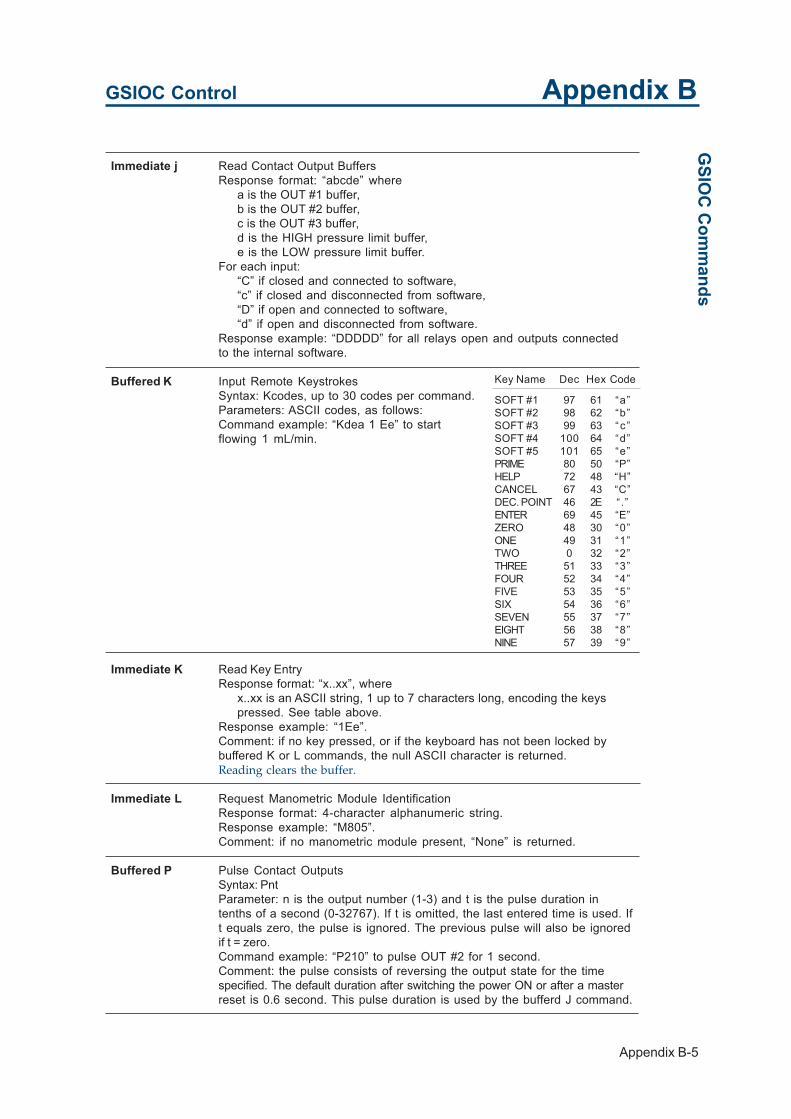
Appendix B-5
GSIOC Control Appendix B
Immediate j Read Contact Output BuffersResponse format: “abcde” where
a is the OUT #1 buffer,b is the OUT #2 buffer,c is the OUT #3 buffer,d is the HIGH pressure limit buffer,e is the LOW pressure limit buffer.
For each input:“C” if closed and connected to software,“c” if closed and disconnected from software,“D” if open and connected to software,“d” if open and disconnected from software.
Response example: “DDDDD” for all relays open and outputs connectedto the internal software.
Buffered K Input Remote KeystrokesSyntax: Kcodes, up to 30 codes per command.Parameters: ASCII codes, as follows:Command example: “Kdea 1 Ee” to startflowing 1 mL/min.
GSIO
C C
omm
ands
Immediate K Read Key EntryResponse format: “x..xx”, where
x..xx is an ASCII string, 1 up to 7 characters long, encoding the keyspressed. See table above.
Response example: “1Ee”.Comment: if no key pressed, or if the keyboard has not been locked bybuffered K or L commands, the null ASCII character is returned.Reading clears the buffer.
Immediate L Request Manometric Module IdentificationResponse format: 4-character alphanumeric string.Response example: “M805”.Comment: if no manometric module present, “None” is returned.
Buffered P Pulse Contact OutputsSyntax: PntParameter: n is the output number (1-3) and t is the pulse duration intenths of a second (0-32767). If t is omitted, the last entered time is used. Ift equals zero, the pulse is ignored. The previous pulse will also be ignoredif t = zero.Command example: “P210” to pulse OUT #2 for 1 second.Comment: the pulse consists of reversing the output state for the timespecified. The default duration after switching the power ON or after a masterreset is 0.6 second. This pulse duration is used by the bufferd J command.
Key Name Dec Hex Code
SOFT #1 97 61 “a”SOFT #2 98 62 “b”SOFT #3 99 63 “c ”SOFT #4 100 64 “d”SOFT #5 101 65 “e”PRIME 80 50 “P”HELP 72 48 “H”CANCEL 67 43 “C”DEC. POINT 46 2E “.”ENTER 69 45 “E”ZERO 48 30 “0”ONE 49 31 “1”TWO 0 32 “2”THREE 51 33 “3”FOUR 52 34 “4”FIVE 53 35 “5”SIX 54 36 “6”SEVEN 55 37 “7”EIGHT 56 38 “8”NINE 57 39 “9”

Appendix B-6
GSIOC Control Appendix B
Buffered Q Enter Pressure ValueSyntax: “QBxx.x” in bars, “QPx.xx” in MPa, or “QKxx.x” in kpsi.Parameter: if xxx is omitted, the pressure value is read from themanometric module and the pressure unit is selected for the immediate Qcommand.Command example: “QP1.23” for 1.23 MPa.Comment: this command does not affect the pressure unit on the display.
Immediate Q Read Pressure ValueResponse format: as above, in the pressure unit used by the last Qbuffered command. The default selection is in bars.Response example: “B321” for 321 bars.Comment: if no manometric module present, “N” is returned.
Buffered W Write DisplaySyntax: “WO = x..xx” for upper line, “W1 = x..xx” for lower line.Parameter: x..xx is a 24-character long alphanumeric string. All 7-bit ASCIIcharacters are valid. Note that characters shown on the Japanese-madedisplay unit may differ from characters sent by a micro-computer (if usedas a master controller).
Immediate W Read DisplayResponse format: “W0 =” (upper line) or “W1 =” (lower line) plus 24-character alphanumeric string.Response example: “W0 = Flow rate 1.000 mL/min”.Comment: the first line to be returned is the last entered by the buffered Wwrite command. If the write command has not been used, the upper line ofdisplay is read at the first occurence of the read command. The other lineis read at the second one. And so on.
Immediate w Read Display BuffersResponse format: as above.Comment: reading mechanism same as above. The response is the imageof the related display line from the buffer. This is also the message whichwill be restored to the display after a partial (W0/W1) or total (W) command.
GSI
OC
Com
man
ds
Identification Number
The Model 305 identification number is factory setto 1. In a multi-pump configuration, it is necessaryto change the addresses of the slave pumpsaccording to the opposite table.
To change the GSIOC ID number, turn the powerON. Press <Menu>, <I/O>, then <Prev>. Thedisplay comes “GSIOC Unit ID: 1”. Key in thedesired number (from 2 to 4) and confirm byhitting <Enter>, then <Quit>.
If a Model 302 or 303 pump is used as a slavepump, its ID number must also be changed bysetting DIP switches on the Thumbwheel PCBoard. See the related User’s Guide on how to setID number.
Slave Pump ID Number
Pump B 2Pump C 3Injection Pump (D) 4
Appendix B-7
GSIOC Control Appendix BG
SIOC
Com
mands
Identification of the master pump (pump A) is notcritical. However, if a Model 305 is used with acomputer-based Gilson system, its ID number mustbe cleaned in the Setup menu of the softwarepackage (Model 704, 712, 714 or 715).
Command Examples
Example 1: GSIOC Command - Zeroing theManometric Module
In order to zero the Manometric Module whencontrolling the 305 from a computer-based systemcontroller, stop all pumps, or pause without flow.This ensures no actual pressure inside theManometric Module. The following GSIOCcommands must be entered:
Send the zeroing K buffered command string. Fromthe ready-to-run menu, this command string ismade up of: Kdbbce.
This mimics the following key entry sequence:<Menu>, <I/O>, <Prev>, <Zero>, and <Quit>.
This command can be sent before the run by usingthe “GSIOC Control” option of the “Manual”menu. It can also be added to the method as aGSIOC event (“Edit” menu, “GSIOC Events” or“Gilson Instruments” option).
Example 2:
To write “HELLO” on theupper line of the displayand “My name is Model305” on the lower line.
Example 3:
To remote read thedisplay.
The use of the lowercasew immediate commandallows you to readmessages displayedbefore the use of the Wbuffered write command.
Command Comment
(B) W0 = HELLO Write on upper line of display
(B) W1 = My name is Model 305 Write on lower line of display
Command Response Comment
(I) W W1 = My name is Model 305 Read last entered line
(I) W W0 = HELLO Read the other line
Command Response Comment
(I) w W1 = Menu Run
(I) w W0 = Flow rate 1.000 mL/min

Appendix B-8
GSIOC Control Appendix BG
SIO
C C
omm
ands Example 4: to restore display messages
This sequence sends “reconnect”commands to the internal softwarefor the two related output devices.Original messages are restored. In thecase where a separate access to thetwo lines of the display is not required,the same action is performed by asingle command as above.
Example 5: to select the flow mode, and startpumping at 1 mL/min.
Codes sent correspond to thefollowing key sequence: <Menu><Mode> <Flow> <1> <Enter> <Run>.The reconnect command is necessaryif a direct access to keyboard keys isrequired.
Command Comment
(B) W0 Reconnect upper line to software.
(B) W1 Reconnect lower line to software.
Command Comment
(B) W Reconnect both lines to software.
(B) W1 Reconnect lower line to software.
Command Comment
(B) Kdea 1Ee Mimic key entries
(B) K Reconnect keyboard to software.

Appendix C-1
Twin-pump Systems Appendix C
In each of the systems outlined in this manual there is a maximum of four pumps. Thesignals from the controller to the pumps are carried on a communications channelcalled the Gilson Serial Input Output Channel, or GSIOC for short. For a single pump-ing system, all of the pumps are connected in parallel and the controller distinguishesbetween any two pumps by a GSIOC identity number which you enter in the software.Each pump must have a different GSIOC identity number.
If we connect the pumps as shown in the following drawings, we have in effect two ormore parallel pumping systems. The same commands will go to each pump associatedwith the same solvent, i.e. pumps A, and A’ will receive the same commands. Pump Band B’ will receive the same commands etc. Each associated pump will operate inexactly the same way, one being a mirror image of the other. In this way, we can createtwo identical, parallel liquid streams with one controller. The hydraulic outlet tubingcan then be connected together to increase the overall flow rate. Theoretically there isno limit to the number of pumps that can be connected in parallel, but effectively atwin system with two liquid streams is the most practical. The advantage of thisarrangement is to be able to use a smaller head and hence work at a higher pressure.For example, two 25SC heads could be used in parallel to obtain a flow rate of 50mL/min. The maximum operating pressure would then be 28 MPa instead of a maxi-mum of 14 MPa with a single 50SC head.
The actual flow rate of the combined pumps is the value programmed in the controllermultiplied by the number of pumps in parallel.

Appendix C-2
Twin-pump Systems Appendix C
Two Possible Cases:- A system of mirror pumps controlled by a 305
Master pump.
- A system of mirror pumps controlled by a com-puter and a Gilson System Controller software.
When using a computer with a HPLC SystemController software, the identity numbers for thepumps can be chosen between 0 and 63.
When using a 305 as a master, the follow-ing identity numbers must be used.
- Pumps A 1- Pumps B 2- Pumps C 3- Pumps Inj 4
The requirements for a parallelsystem are:
- All pumps must be Model 305 or306.
- Each pump in parallel, (A + A’, B+ B’, etc...), must have the sameheadsize.
- Each pump in parallel must havethe same GSIOC identity number,e.g. A and A’ pumps must be 1.
Diagrams of the electrical connec-tions for the GSIOC cables aregiven in the opposite figures.
pump A1
M S
pump B2
M S
pump C3
M S
pump D4
M S
pump A'1
S
pump B'2
S
pump C'3
S
pump D'4
S
305 305 305 305
306 306 306 306
S Mpump D
S Mpump C
S Mpump B506/621
Interface
Computerwith 712or 714
software
S pump A'
S pump B'
S pump C'
S pump D'
S Mpump A
305s 306s
M represents the GSIOC toSLAVE socket.
S represents the GSIOC FROMCONTROLLER socket.
Two
Poss
ible
Cas
es

Appendix D-1
Reference Informations Appendix D
This chapter contains Table of Solvent Miscibility, Liquid Compressibility Values andFlow Rate Accuracy Principle.

Appendix D-2
Reference Informations Appendix D
Solvent Miscibility Table
Miscibility means that solvents should mix with eachother in all proportions. That solvents should bemiscible is important both during elution and whenswitching from one solvent to another. You areadvised to refer to the table, below, when selectingsolvents. For some solvents, lower toxicityalternatives are indicated [(1), (2), (3)], as follows:
ACETIC ACID
ACETONE
ACETONITRILE
BUTYL ALCOHOL
CHLOROFORM (1)
CYCLOHEXANE
DICHLOROETHANE (1)
DICHLOROMETHANE
DIMETHYLFORMAMIDE
DIMETHYL SULFOXIDE
DIOXAN (2)
ETHYLACETATE
ETHANOL
DI-ETHYLETHER
HEPTANE
HEXANE
METHANOL (3)
METHYLETHYL KETONE
I-OCTANE
PENTANE
ISOPROPANOL
DI-PROPYLETHER
TETRAHYDROFURAN
TOLUENE
WATER
XYLENE
MISCIBLE
IMMISCIBLE
(1) Dichloromethane(2) Tetrahydrofuran(3) Ethanol
Solv
ent M
isci
bilit
y Ta
ble

Appendix D-3
Reference Informations Appendix D
Liquid Compressibility Values
Bibliography Data
The values of isothermalcompressibility given belowcan be used for theCompressibility value in thepump setup menu. Thesevalues are given underathmospheric pressure (X0)and are expressed in Mbar-1.
The opposite table refers toHandbook of Chemistry andPhysics, CRC Press, 60th Ed.(1979).
Liquid Com
pressibility Values
Liquid Temperature Compressibility(°C) (Mbar-1)
Water 20 4625 4630 4540 4540 44
Benzene 20 94-9525 96-9730 101-10340 110
Chloroform 20 97-10125 9730 108-11040 118-119
Methylene chloride 25 97
Carbon tetrachloride 20 103-10525 106-10830 112-11340 120-122
Ethanol 20 110-11225 114-11630 118-11940 126-127
Acetone 20 123-12725 12430 13340 144-156
Methanol 20 121-12325 125-12730 129-13040 138
n-Heptane 20 140-14525 142-14930 150-15540 160
n-Hexane 20 150-16525 161-17130 165-18040 183
Diethyl ether 20 184-18725 195-20030 208-209

Appendix D-4
Reference Informations Appendix DLi
quid
Com
pres
sibi
lity
Valu
es Other Data
For other liquids currently used atambient temperatures (20-25 °C), thefollowing data is given. This data is aresult of experiments done using the 305pump, the figures are not presented asphysical constants of scientific value.
If no data is available in this chapter forthe liquid you use, and if you wish anaccuracy error within the specifications,you can experimentally determine avalue to reach this goal.
To do so, use a trial-and-error empirical method.Select the initial value for Liquid Compressibilityaccording the following guidelines:
- For an organic solvent, take a value given for thesame, or similar, chemical family.
- For a mixture, including salt aqueous solutions,take the value of the dominant solvent.
Pump your liquid under high pressure to obtain asignificant error, preferably use a gravimetricmethod if you know the density of the liquid.
Then, with a few successive approximations, adjustthe Liquid Compressibility value by assuming alinear relationship between this parameter and theresulting error.
Liquid Compressibility(Mbar-1)
Acetonitrile 99
Tetrahydrofuran 93
Water-methanol, 10-90 (v-v) 117“ 20-80 “ 86“ 40-60 “ 56“ 50-60 “ 52“ 60-40 “ 46“ 80-20 “ 40
Appendix D-5
Reference Informations Appendix DFlow
Rate A
ccuracy Principle
Flow Rate Accuracy PrincipleTo generate the selected flow rate with high accuracy,maintained under high pressure and for a variety ofliquids, the 305 software adds to complementarycorrections to the basic “piston flow rate”. Definedfrom the piston stroke volume only, the piston flowrate is theoretically accurate at athmospheric pres-sure only.
The objective flow rate, F, is considered as the sumof three components:
F = F0 + F1 + F2
F0, the piston flow rate decreases when pressureincreases;F1, the compensation flow rate for the liquid com-pressibility, increases with pressure;F2, the compensation flow rate for all others factors,also increases with pressure.
The piston flow rate, F0, is defined by:F0 = N0 VS
with N0, number of piston cycles per unit time; andVS, piston stroke volume.
The compensation flow rate for the liquid compress-ibility, F1, is calculated as a function of five variables:
F1 = f1 (F0, VS, VD, P, X)where VD is the volume of the dead space inside thecompression chamber; P, the operating pressure;and X, the compressibility of the liquid under thepressure P.
In the 305 software, X is calculated using the simpli-fied Tait equation:
X = c P + d
Coeeficient c varies only slightly with the nature ofthe liquid. It is a constant included in the software.Coefficient d is calculated from the Liquid Com-pressibility at athmospheric pressure, X0 (for P = 0),entered by the user as a “set-up” parameter. Valuesof X0 for some common solvents are tabulated inthe previous page.Operating pressure, P, is continuously transmittedto the pump by the Manometric Module (pressurefeedback).

Appendix D-6
Reference Informations Appendix D
The complementary compensation flow rate for allother factors, F2, is defined as the difference:
F2 = F (F0 + F1)It was measured and the experimental results wereexpressed using a simple function of operatingpressure P:
F2 = f2 (a, b, P)Coefficients a and b were determined for each pumphead. They are manufacturing constants attached tothe parameter Head Size, a second ‘Setup’ parameterentered by the user.
All of these factors taken together allow the 305 todeliver a highly accurate flow rate, independent ofthe pump head size, type of liquid and pressure.
Flow
Rat
e A
ccur
acy
Prin
cipl
e

Appendix E-1
305 Programming Sheet Appendix E
The programming sheets provided on the next pages should be properly filled outprior to programming the pump.
This wil ensure that the parameters are entered correctly, and will enable you toquickly cross check them when required.

Appendix E-2
305 Programming Sheet Appendix E
Set Up Parameters
Step No Time Event Operation Step No Time Event Operation
1 13
2 14
3 15
4 16
5 17
6 18
7 19
8 20
9 21
10 22
11 23
12 24
File Number Method Name Composition and Flow
Set Up Parameters
Pressure: High limit = Low limit = Units:
Number of pumps = Loops = Link file =
Pump Model Solvent I.D Refill Comp Head size
A
B
C
Inj.
mL/
min
Time (min)
% C
Time (min)
% B
Time (min)
I/O Operations
Time Contact State Function

Appendix E-3
305 Programming Sheet Appendix EExam
ple

Appendix E-4
305 Programming Sheet Appendix E

Appendix F-1
Technical Data Appendix F
The following information presents construction and operational characteristics forGilson 305 Pumps.

Appendix F-2
Technical Data Appendix FTy
pe o
f Pum
p Type of Pump
Programmable reciprocating pump with single-piston interchangeable head, constant stroke, andspecial fast-refill motion.

Appendix F-3
Technical Data Appendix FW
orking Range &
Performance D
ata
Working Range & Performance Data
Working Range, Pump Heads andassociated Manometric Modules
A complete Gilson liquid delivery system includes upto four pumping modules with appropriate heads, amanometric module and a mixer for gradientelution.
Pump Flow rate Pressure Manometrichead range* range* module
(model) (mL/min) (MPa) (model)
5SC 0.010 - 5 0.1 - 60 80510SC 0.050 - 10 0.1 - 60 805
10WSC 0.050 - 10 0.1 - 60 80510WTi 0.050 - 10 0.1 - 60 80525WTi 0.125 - 25 0.1 - 28 80625SC 0.125 - 25 0.1 - 28 80650SC 0.250 - 50 0.5 - 14 806
100SC 0.500 - 100 0.5 - 7 807200WTi 1.000 - 200 0.5 - 3.5 807
Adjustable Parameters
Liquid compressibility, refill time and inlet pressure.Compressibility from 0 to 2000 Mbar -1, refill time from125 to 1000 ms and inlet pressure from 0 to 10 MPa.
Residual Pulsations
Typically less than 1 %.
Flow Rate Precision and Accuracy at20°C over full working range
Coefficient of Variation
0.1 to 0.6% with aqueous solutions or hydro-organicpolar solvent mixtures and 0.3 to 1% withhydrocarbons or chlorinated volatile solvents.
Maximum Accuracy Error
±1% with water over the full flow rate and pressureranges.
SC:Standard self-centering piston.
Ti: Titanium liquid contact-parts.
W: Washing compartment forsalt-concentrated solutions(> 0.1M).
*: Minimum values for the flowrate and pressure are notabsolute limits, they areindicated to obtain specififiedprecision and accuracy.Flow rate is adjustable downto 0.01 % of the maximumflow rate.

Appendix F-4
Technical Data Appendix FW
orki
ng R
ange
& P
erfo
rman
ce D
ata Liquid-contact Materials
316L stainless steel, titanium, sapphire/ceramic,ruby, PCTFE, PEEK, PTFE/HDPE.
Binary Gradient Systems (two-solventcomposition programming)
Mean Accuracy Error
< ± 3 % determinated in the range 0 - 10 % by 1 %steps and in the range 0 - 100 % by 10 % steps.
Deviation from Linearity
< ± 1 %.
Repeatability
< 1 % maximum imprecision for any composition.
Repeatability of gradient HPLC analysis (ICI test Ffor liquid chromatographs):
< 0.2 % for retention times, and < 0.7 % for peaks areas.
These specifications are valid for any model ofthe 305 technology in the following conditions :
liquids of known compressibility, pumped atambient temperatures (20-25 °C), in the entirepressure range, with any pair of identical pumpheads operating within the ranges indicatedhereafter.
Total Delay Volume (ASTM E-19.09.07)
1.2 mL dynamic mixing chamber, in-line filter (0.5 µm,0.4 mL) and 0.5 x 500 mm tubing.
Effective Mixing Volume (ASTM E-19.09.07)
1.1 mL in the same conditions as above.
Composition Total flow rate(% of solvent B) (% of maximum)
1 - 99 100 - 502 - 98 50 - 255 - 95 25 - 10
10 - 90 10 - 5

Appendix F-5
Technical Data Appendix FC
ontrol and Interfaces
Control and Interfaces
Operation Modes
Constant flow rate (Flow), constant volume(Dispense), and timed-based sequence (Program) forup to four Gilson pumps controlled either by one305 acting as a Master 305, or by an externalcomputer.
Programmable Parameters
Solvent composition points for high pressure mixingof 3 solvents from 3 pumps.
Flow rate points that can be superimposed overgradient composition profile.
Timed events for programming 3 output contactclosures, 1 input and 1 injection pump.
Time, adjustable from 10-2 to 104 min, withincrements from 0.001 to 1 min depending on therange used.
Flow control, adjustable from 0.01 % to 100 % of themaximum flow rate of the pump head being used.
Possibility to program 999 loops with unlimitedlinking of files.
Storage for 10 user programs and 4 error files with amaximum of 25 points and timed events in eachprogram.
Dispense Mode
The dispensed volume is fully adjustable, in mL,between 10-4 and 100 mL multiplied by the modelnumber of the pump head. The same range is availablefor the injection pump in the program mode.
User Interface
2-line, 48-character LCD display.
Front panel keypad.
Built-in help messages.

Appendix F-6
Technical Data Appendix FC
ontr
ol a
nd In
terf
aces Electrical Interface
4 inputs, 3 programmable outputs.
Digital Interface
Gilson Serial Input/Output Channel.
The pump can act as master or slave.

Appendix F-7
Technical Data Appendix FEnvironm
ental Conditions
Environmental Conditions
Storage
Indoor use only.
Installation : Category II.
Altitude: Up to 2000 m.
Temperature range: 4 - 40 °C.
Pollution degree 2.
Humidity: Up to 80 %.
Power Requirements
Frequency: 50 to 60 Hz.
Voltage: 100 to 240 Vac.
Power rating: 110 VA.
Size and Weight
Size (W x D x H): 330 x 330 x 150 mm.
Weight: 10 kg (22 lb).

Appendix F-8
Technical Data Appendix F


World Wide Web: www.gilson.comE-mail: [email protected], [email protected], [email protected]
World HeadquartersGilson, Inc.3000 W. Beltline Hwy., P.O. Box 620027, Middleton, WI 53562-0027, USATelephone: (1) 800-445-7661 or (1) 608-836-1551 • Fax: (1) 608-831-4451
Gilson SAS19 avenue des Entrepreneurs,95400 Villiers-le-Bel, FranceTelephone: (33) 1-34-29-50-00 • Fax: (33) 1-34-29-50-20