30.10.2019 product manual abb welcome ip · 2019-10-31 · intended use product manual...
TRANSCRIPT

2TMD041800D0088 │ 30.10.2019
Product manualABB-Welcome IP
D0401. Smart Access PointD0401.-02 Smart Access Point

Table of contents
Product manual 2TMD041800D0088 │2
Table of contents
1 Notes on the instruction manual .................................................................................................................... 5
2 Safety ............................................................................................................................................................. 5
3 Intended use .................................................................................................................................................. 53.1 Typical application .............................................................................................................................. 6
4 Environment ................................................................................................................................................... 84.1 ABB devices ....................................................................................................................................... 8
5 Product description ........................................................................................................................................ 9
6 Technical data ............................................................................................................................................. 11
7 Mounting/Installation .................................................................................................................................... 127.1 Requirement for the electrician ........................................................................................................ 127.2 Mounting ........................................................................................................................................... 13
8 Commissioning ............................................................................................................................................ 158.1 Registering an account on the MyBuildings portal .......................................................................... 158.2 Access SmartAP .............................................................................................................................. 16
8.2.1 Access SmartAP through UPnP .....................................................................................................168.2.2 Access SmartAP through AP mode ...............................................................................................17
8.3 Initial setup ....................................................................................................................................... 208.4 Home screen .................................................................................................................................... 32
8.4.1 Configuration screen ......................................................................................................................328.5 Settings ............................................................................................................................................ 34
8.5.1 Access quick settings .....................................................................................................................348.5.2 Access general settings .................................................................................................................358.5.3 Version information ........................................................................................................................368.5.4 Disclaimer information ....................................................................................................................378.5.5 Language ........................................................................................................................................388.5.6 Time settings ..................................................................................................................................398.5.7 Network settings .............................................................................................................................428.5.8 AP mode settings ...........................................................................................................................438.5.9 Third part authority settings ............................................................................................................448.5.10 Abnormal devices ...........................................................................................................................458.5.11 Onvif IPC settings ...........................................................................................................................468.5.12 Alarm notification settings ..............................................................................................................508.5.13 MyBuildings settings .......................................................................................................................518.5.14 Project backup ................................................................................................................................538.5.15 Restore to default settings ..............................................................................................................568.5.16 Firmware update of SmartAP .........................................................................................................588.5.17 Reset the password for the first admin...........................................................................................59
9 Operation ..................................................................................................................................................... 619.1 Device management ........................................................................................................................ 61
9.1.1 Adding DES devices .......................................................................................................................619.1.2 Adding VideoControl devices .........................................................................................................659.1.3 Configure indoor stations ...............................................................................................................66

Table of contents
Product manual 2TMD041800D0088 │3
9.1.4 Configure outdoor stations .............................................................................................................729.1.5 Configure guard unit .......................................................................................................................839.1.6 Configure IP actuator .....................................................................................................................859.1.7 Configure IPC .................................................................................................................................909.1.8 Configure devices in batch .............................................................................................................939.1.9 Removing devices ..........................................................................................................................95
9.2 User management ............................................................................................................................ 969.2.1 Enter the settings ............................................................................................................................969.2.2 Adding users ...................................................................................................................................979.2.3 Configuring users ...........................................................................................................................989.2.4 Removing users ..............................................................................................................................999.2.5 Adding a user group .................................................................................................................... 1009.2.6 Configuring a user group ............................................................................................................. 1019.2.7 Removing a user group ............................................................................................................... 1029.2.8 Assigning the users to a user group ............................................................................................ 1039.2.9 Removing the users from a user group ....................................................................................... 1049.2.10 Assigning ID authentications to a user ........................................................................................ 1059.2.11 Removing ID authentications from a user ................................................................................... 1089.2.12 Assigning the locks to a user ...................................................................................................... 1099.2.13 Assigning the locks to a user group ............................................................................................ 1109.2.14 Removing the locks from a user .................................................................................................. 1119.2.15 Removing the locks from a user group ....................................................................................... 1129.2.16 Pairing APP to a user .................................................................................................................. 1139.2.17 Removing APP from a user ......................................................................................................... 118
9.3 Creating actions ............................................................................................................................. 1199.3.1 Enter the settings ......................................................................................................................... 1199.3.2 Creating a new action .................................................................................................................. 1209.3.3 Configuring the action ................................................................................................................. 1229.3.4 Removing the action .................................................................................................................... 123
9.4 History ............................................................................................................................................ 1249.4.1 Notification ................................................................................................................................... 1249.4.2 Alarm record ................................................................................................................................ 1269.4.3 Logs ............................................................................................................................................. 127
9.5 Message center .............................................................................................................................. 1289.5.1 Access "Message center" screen ................................................................................................ 1289.5.2 Creating and sending a message ............................................................................................... 1299.5.3 Viewing and replying to a message ............................................................................................ 130
9.6 Emergency unlock .......................................................................................................................... 1319.7 Online firmware update .................................................................................................................. 132
10 FCC ............................................................................................................................................................ 133
11 Cyber security ............................................................................................................................................ 13411.1 Disclaimer ....................................................................................................................................... 13411.2 Performance and service and network performance ..................................................................... 13411.3 Deployment guideline .................................................................................................................... 13611.4 Upgrading ....................................................................................................................................... 13611.5 Backup/restore ............................................................................................................................... 13611.6 Data pursing ................................................................................................................................... 137

Table of contents
Product manual 2TMD041800D0088 │4
11.7 Malware prevention solution .......................................................................................................... 13811.8 Default passwords and user accounts ........................................................................................... 13811.9 Password rule ................................................................................................................................ 13811.10 Logging ........................................................................................................................................... 139

Notes on the instruction manual
Product manual 2TMD041800D0088 │5
1 Notes on the instruction manual
Please read through this manual carefully and observe the information it contains. This willassist you in preventing injuries and damage to property, and ensure both reliable operation anda long service life for the device.
Please keep this manual in a safe place. If you pass the device on, also pass on this manualalong with it. ABB accepts no liability for any failure to observe the instructions in this manual.
2 Safety
WarningElectric voltage!Dangerous currents flow through the body when coming into direct or indirectcontact with live components.This can result in electric shock, burns or even death.– Disconnect the mains power supply prior to installation and/or disassembly!– Permit work on the 100-240 V supply system to be performed only by
specialist staff!
3 Intended use
As a part of the ABB-Welcome IP system, this device can only be used with accessories fromthe system

Intended use
Product manual 2TMD041800D0088 │6
3.1 Typical application
1. Single family house
If SmartAP is used in a single family house to control all devices in the house, it should be set to"Residential".
Connection of indoor stations
If LAN+LAN indoor station (Article no. is H82635.-.) is used as a master indoor station, LAN2 isto be connected to the router by default.
If LAN+Wifi indoor station (Article no. is H82634.-.) is used as a master indoor station, the wifiport is to be connected to the router only.
SmartAP (Residential)
Master IS
Private IP actuatorCAT.5/IP bus line
Router switch
Wifi
APP
Villa OS
Slave IS
IP camera
POE
Internet
Master IS Slaver IS
LAN2 (default) LAN2 (default)
LAN1 (default)Wifi only
Wifi
Router Router
Router Router
LAN+WifiH82364.-.
LAN+WifiH82364.-.
LAN+WifiH82364.-.
LAN+LANH82365.-.
LAN+LANH82365.-.
Or
Router

Intended use
Product manual 2TMD041800D0088 │7
2. High rise building
If SmartAP is used in a high rise building to control all devices in this building, it should be set to"Functional".
Connection of indoor stations
LAN1 of master indoor station should be connect to the switch placed in the building.
SmartAP (Functional)
Building OS
Building IP actuator
IP camera
POE
POE
POE
POE
POE
...
Master IS
Master IS
Master IS
Master IS
Master IS
Master IS
Master IS
Master IS
CAT.5/IP bus line
Apartment
Building
Master IS
Router
2nd confirmed OS
Slave IS
Private IP actuator
Master IS Slaver IS
LAN1 (default) LAN2 (default)
LAN1 (default)LAN1 only
Wifi
Switch
Switch
Router
Router
LAN+WifiH82364.-.
LAN+WifiH82364.-.
LAN+WifiH82364.-.
LAN+LANH82365.-.
LAN+LANH82365.-.
Or
Router
POE
POE

Environment
Product manual 2TMD041800D0088 │8
4 Environment
Consider the protection of the environment!Used electric and electronic devices must not be disposed of with householdwaste.– The device contains valuable raw materials that can be recycled. Therefore,
dispose of the device at the appropriate collecting facility.
4.1 ABB devices
All packaging materials and devices from ABB bear the markings and test seals for properdisposal. Always dispose of the packing materials and electric devices and their components viaan authorized collection facility or disposal company.
ABB products meet the legal requirements, in particular the laws governing electronic andelectrical devices and the REACH ordinance.
(EU-Directive 2012/19/EU WEEE and 2011/65/EU RoHS)
(EU-REACH ordinance and law for the implementation of the ordinance (EG) No.1907/2006)

Product description
Product manual 2TMD041800D0088 │9
5 Product description
No. Function
1 USB stick connector (reserved)
2 Tamper switch
3 (1) Status indicator
4 Binary input (used to interact with other systems)
5 Binary output (used to interact with other systems)
6Reset buttonPress and hold this button for 10 s to reset the password of the first admin. Please see the"Reset the password for the first admin" chapter for more details.
7Switch for operation in AP modeWhen AP mode is activated, LED flashes red light.
8 Micro SD card connector (reserved)
9Security switchON = does not allow/delete the devicesOFF = allows add/delete the devices (default)
10 Power input connector (DC-JACK input)
11 LAN (PoE)
1 2 3 54
6789
1011

Product description
Product manual 2TMD041800D0088 │10
(1) Status indicator
Description Blue Red Green White Priority
Reset to factory default Flashingslowly 7 (Highest)
Alarm (e.g. tamper alarm) Flashingquickly 6
Power on or Initial setup on 5
AP mode is enabled Flashingslowly 4
Security mode is disable on 3
Doorbell is muted on 2
Normal operation on 1

Technical data
Product manual 2TMD041800D0088 │11
6 Technical data
Designation Value
Rating voltage 24 V DC
Operating voltage range 20-27 V DC
Rating current 24 V DC, 375 mA
PoE standard IEEE802.3 af
Wireless transmission band
802.11b/g/n:2412...2462MHz (for United States)2412...2472MHz (for European countries)802.11a/n:5150…5250MHz5250…5350MHz5470…5725MHz5725…5850MHz (for United States)
Wireless transmission powerMax. 20 dBm@12 Mbps OFDM 2.4 GMax. 20 dBm@12 Mbps OFDM 5.8 G
Wireless transmission standard IEEE 802.11 a/b/g/n
Operating temperature -10 °C…+45 °C
Storage temperature -25 °C…+70 °C
Product dimensions 204 mm × 132 mm × 32 mm
IP level IP 30
IK level IK 05
Relay output 30 V DC, 1 A
Dry contact input 5 V DC, 1mA

Mounting/Installation
Product manual 2TMD041800D0088 │12
7 Mounting/Installation
WarningElectric voltage!Dangerous currents flow through the body when coming into direct or indirectcontact with live components.This can result in electric shock, burns or even death.– Disconnect the mains power supply prior to installation and/or disassembly!– Permit work on the 100-240 V supply system to be performed only by
specialist staff!
7.1 Requirement for the electrician
WarningElectric voltage!Install the device only if you have the necessary electrical engineeringknowledge and experience.– Incorrect installation endangers your life and that of the user of the electrical
system.– Incorrect installation can cause serious damage to property, e.g. due to fire.The minimum necessary expert knowledge and requirements for the installationare as follows:– Apply the "five safety rules" (DIN VDE 0105, EN 50110):
1. Disconnect2. Secure against being re-connected3. Ensure there is no voltage4. Connect to earth and short-circuit5. Cover or barricade adjacent live parts.
– Use suitable personal protective clothing.– Use only suitable tools and measuring devices.– Check the type of supply network (TN system, IT system, TT system) to
secure the following power supply conditions (classic connection to ground,protective grounding, necessary additional measures, etc.).

Mounting/Installation
Product manual 2TMD041800D0088 │13
7.2 Mounting
1. Dismantle
Pull the clamp on the bottom of the device and then open the front cover.
2. Wiring
Option 1: Wiring from the back
Option 2: Wiring from the bottom
Option1
Option2

Mounting/Installation
Product manual 2TMD041800D0088 │14
3. Mounting

Commissioning
Product manual 2TMD041800D0088 │15
8 Commissioning
8.1 Registering an account on the MyBuildings portal
Öffnen Sie den Link: https://mybuildings.abb.com und klicken Sie auf „Registrieren“. Füllen Siedas Formular aus, um ein Benutzerkonto anzulegen. Aktivieren Sie Ihr Benutzerkonto, wenn Siedie E-Mail vom MyBuildings-Portal erhalten.

Commissioning
Product manual 2TMD041800D0088 │16
8.2 Access SmartAP
8.2.1 Access SmartAP through UPnP
PC must connect to the router first.
Please follow the steps below on the PC:
PCPCPC
SmartAPSmartAPSmartAP
RouterRouter
Router
LAN connection Wifi connection

Commissioning
Product manual 2TMD041800D0088 │17
8.2.2 Access SmartAP through AP mode
SmartAP works in AP mode■ SmartAP enters AP mode automatically when it is powered on for the first time and LED
light white.■ SmartAP enters AP mode automatically after initial setup and LED flashes red.■ Press AP mode switch will switch on/off AP mode, LED flashes red if SmartAP works in AP
mode.
Access SmartAP on website
On PC, open the network setting, click the designated WLAN name, and enter the password.
You can use the original password before initial setup.
You need to use a new password after initial setup.
AP mode swi tch
LED

Commissioning
Product manual 2TMD041800D0088 │18
Obtain original WLAN name and password
Open the front cover of SmartAP, you can find the original WLAN name and password on asticker.
12
LED
CNE105807A7F02D590
Sm artAP
CNE105807A7F02D590
Network settingsSmartAP
WLAN: SmartAP_xxxx
PW: xxxxxxxxxxIP: 192.168.3.1
C N E
105807A7F02D590
Network s e ttingsSm artAP
WLA N : S m ar t A P _xxxx
P W: xxxxxxxxxxI P : 192. 168. 3. 1

Commissioning
Product manual 2TMD041800D0088 │19
On PC, enter the IP address of AP mode (default is "192.168.3.1") to access SmartAP.
You need to enter new IP address if you change it on the "Wi-Fi access point mode settings"screen.

Commissioning
Product manual 2TMD041800D0088 │20
8.3 Initial setup
1. Switch to security login
It is recommend to use HTTPS to encrypt data.
Click "Switch to security login" - "Advanced" - "Proceed to …" to switch to security screen.

Commissioning
Product manual 2TMD041800D0088 │21
2. Select language
Select the language from the list.
3. Accept end user license

Commissioning
Product manual 2TMD041800D0088 │22
4. Accept OSS license
5. Accept data privacy

Commissioning
Product manual 2TMD041800D0088 │23
6. Choose building type
Please see the "Typical application" chapter for more details.
7. Define your location
Select time zone from the drop-down list.

Commissioning
Product manual 2TMD041800D0088 │24
8. Change AP mode Wi-Fi setting and set country code
It is forced to change the WLAN name and password on initial setup. It is recommended tomake a new sticker and affix it to the cover of the device.

Commissioning
Product manual 2TMD041800D0088 │25
9. Select connection type
Select a connection type according to the diagram below.
Selection type = LAN
PCPCPC
SmartAP(Funcitonal)
Connection type = LAN Connection type = Wifi
SmartAP(Residential)
SmartAP(Residential)
Router
Switch
Router

Commissioning
Product manual 2TMD041800D0088 │26
Selection type = Wi-Fi
10. Create the first admin user
Here you create the first admin user.

Commissioning
Product manual 2TMD041800D0088 │27
11. MyBuildings login[1] Security lever 1: Reset the password for the first admin without MyBuildings account
No. Description
1 If you don’t make any settings on this screen, you can click "Skip" to access next screen.
2 If you do not have a MyBuildings account, click "register here" to create one.
3 Enter the user name, password and friendly name
4 If "Remote access" function is enables, you can access SmartAP on the MyBuildings portal ifyou have subscribed to the remote service.
Please see the "Reset the password for the first admin" chapter for more details.

Commissioning
Product manual 2TMD041800D0088 │28
[2] Security lever 2: Reset the password for the first admin with MyBuildings account
No. Description
1 If you do not have a MyBuildings account, click "register here" to create one.
2 Enter the user name, password and friendly name
3 Enter the email for resetting the password for the first admin
4 If the "Remote access" function is enabled, you can access SmartAP on the MyBuildings portalif you have subscribed to the remote service.

Commissioning
Product manual 2TMD041800D0088 │29
Click "Connect" and you will receive an email with the verification code.
Enter this verification code and click "√".
Please see the "Reset the password for the first admin" chapter for more details.

Commissioning
Product manual 2TMD041800D0088 │30
12. Set the device name
This device name will be displayed on the log in screen.
13. Confirm the settings
You can see all the settings on the overview screen. Click "Finish" if the settings are OK.

Commissioning
Product manual 2TMD041800D0088 │31
14. Access log in screen
No. Description
1 Device name
2 User name and password
3Access configuration screenThis function is only available for the admin user and master user.
4 Switch to security login

Commissioning
Product manual 2TMD041800D0088 │32
8.4 Home screen
8.4.1 Configuration screen
No. Description
1Quick settingClick "∨" to access quick settings on a drop-down sidebar.
2NotificationAvailable notifications are displayed by means of a red dot. The digit indicates the number ofavailable messages. Please see the "Notification" chapter for more details.
3Message centerManage the messages between the indoor stations and SmartAP. Please see the "Messagecenter" chapter for more details.
4Emergency unlockClick the icon to release all the locks in the event of an emergency. Please see the "Emergencyunlock" chapter for more details.
5Import building structure from APPPlease see the "Import building structure from APP" chapter for more details.
6Online firmware updatePlease see the "Online firmware update" chapter for more details.

Commissioning
Product manual 2TMD041800D0088 │33
No. Description
7User managementPlease see the "User management" chapter for more details.
8ActionsPlease see the "Create actions" chapter for more details.
9Time controlPlease see the "Time control" chapter for more details.
10Configure the devices on Door entry systemPlease see the "Configure the devices on Door entry system " chapter for more details.
11Active accountHere the logout can be carried out and the password for the access can be changed.
12Device configurationPlease see the "Device configuration" chapter for more details.
13SettingsPlease see the "Settings" chapter for more details.

Commissioning
Product manual 2TMD041800D0088 │34
8.5 Settings
8.5.1 Access quick settings
On the configuration screen, click "∨" to access quick settings.

Commissioning
Product manual 2TMD041800D0088 │35
8.5.2 Access general settings
On the configuration screen, click "Preferences" to access the settings.

Commissioning
Product manual 2TMD041800D0088 │36
8.5.3 Version information
On the "Preferences", "System information" screen, you can view the version information

Commissioning
Product manual 2TMD041800D0088 │37
8.5.4 Disclaimer information
On the "Preferences", "System information" screen, you can view the disclaimer information.

Commissioning
Product manual 2TMD041800D0088 │38
8.5.5 Language
On the "Preferences", "Localization" screen, select the language from the drop-down list.

Commissioning
Product manual 2TMD041800D0088 │39
8.5.6 Time settings
Time zone setting
On the "Preferences", "Localization" screen, select time zone from the drop-down list

Commissioning
Product manual 2TMD041800D0088 │40
Sync SmartAP time with local system or NTP server
On the "Preferences", "Localization" screen, SmartAP time can be set to sync from "Localsystem time" or from "NTP time service".

Commissioning
Product manual 2TMD041800D0088 │41
Sync SmartAP time with other devices on the system
On the "Preferences", "Misc settings" screen, you can select "Automatically" to sync SmartAPtime with other devices on the system regularly. You need to click "Apply" before the change iseffective.

Commissioning
Product manual 2TMD041800D0088 │42
8.5.7 Network settings
On the "Preferences", "Network settings" screen, you can change the network settings. Pleasesee the "Initial setup" chapter for more details.

Commissioning
Product manual 2TMD041800D0088 │43
8.5.8 AP mode settings
On the "Preferences", "Wi-Fi AP mode settings" screen, you can change the AP mode settings.

Commissioning
Product manual 2TMD041800D0088 │44
8.5.9 Third part authority settings
On the "Preferences", "Third party authority" screen, click "add" and enter the IP address andthe port number, then click "Applied" to apply the setting.

Commissioning
Product manual 2TMD041800D0088 │45
8.5.10 Abnormal devices
On the "Preferences", "Abnormal devices" screen, you can view the details of abnormal devices(e.g. device sign failed, communication failed etc.).
You can check the device when "Device signed failed" appears on the abnormal devices list.■ Has the device been signed before?■ Does the device work in safety mode?■ Does the IP address of the device conflict with other devices?

Commissioning
Product manual 2TMD041800D0088 │46
8.5.11 Onvif IPC settings
Indoor station can’t use "Community monitor" function before IPCs are set here.
On the "Configuration", "Protocol", "Protocol info" screen of the IPC, protocol must be set to"Onvif".
On the "Configuration", "Stream", "Base Stream" screen of the IPC, "Video Encode type" mustbe set as "H264" and "Resolution" is not more than "1920x1080".

Commissioning
Product manual 2TMD041800D0088 │47
On the "Configuration", "Device", "Local Network" screen of the IPC, turn off DHCP and set theIP address to 10.0.0.x.

Commissioning
Product manual 2TMD041800D0088 │48
On the "Preferences", "Onvif IPC list" screen of SmartAP, click "Search device" to search thecameras used for the public network.
Then click "Enter credentials" after the IPC is detected.

Commissioning
Product manual 2TMD041800D0088 │49
Enter the user name and the password of the camera, then click "Pair".

Commissioning
Product manual 2TMD041800D0088 │50
8.5.12 Alarm notification settings
On the "Preferences", "Misc settings" screen, the sound notification and popup notification areonly available when the "Alarm when devices goes offline" function is enabled.
NoteThe alarm is reported via outdoor station 1 (device ID=1) or via gate station 1(device ID=1). If either of these two devices cannot be detected in the system,the alarm cannot be reported to SmartAP successfully.

Commissioning
Product manual 2TMD041800D0088 │51
8.5.13 MyBuildings settings
"Pair" is displayed when the account and password are correct.
"Connect" is displayed when SmartAP is connected to the MyBuildings portal successfully.
If "Remote access" is enabled, you can access SmartAP on the MyBuildings portal. But youneed to subscribe to the "Remote access" service on the MyBuildings portal before this functionis used.

Commissioning
Product manual 2TMD041800D0088 │52
Refresh the license
You can refresh the license after the remote service is subscribed.
On the "Preferences", "MyBuildings", "License" screen, click " " to refresh the license.

Commissioning
Product manual 2TMD041800D0088 │53
8.5.14 Project backup
1. Create a backup
On the "Preferences", "Project backups" screen, click " ", enter the name and description,then click "Save" to create a backup onto the SmartAP.

Commissioning
Product manual 2TMD041800D0088 │54
2. Restore the backup
On the "Preferences", "Project backups" screen, click a backup, then click "Restore projectbackup".
3. Export the backup to PC
On the "Preferences", "Project backups" screen, click a backup, enter a recovery password andthen click "Export" to export the backup to PC.
NoteThis recovery password is set by you and it is used to import back the samebackup from the PC.

Commissioning
Product manual 2TMD041800D0088 │55
4. Import the backup from PC
On the "Preferences", "Project backups" screen, click " ", enter the recovery password andupload the backup form PC, click "√" to restore the backup. The system will restart when thedatabase has been restored.

Commissioning
Product manual 2TMD041800D0088 │56
8.5.15 Restore to default settings
On the "Preferences", "Service" screen, click "Restore default settings", then select the settingsto be restored.
No. Description
1 Reset the data set on "Actions" and "Time control".
2 Reset the data set on "Preference" - "MyBuildings".
3 Clear the data set on "User management".
4 Click "Factory settings" to select all options and restore all data to factory settings.

Commissioning
Product manual 2TMD041800D0088 │57
You need to enter the verification code to continue the operation if SmartAP is set to securitylevel 2. Please see the "Mybuilings login" chapter for more details.

Commissioning
Product manual 2TMD041800D0088 │58
8.5.16 Firmware update of SmartAP
1. Download SmartAP firmware
On the "Preferences", "Firmware update" screen, you can click the link "on the website" todownload the firmware of SmartAP from the website or you can tick the checkbox to downloadthe firmware automatically. The firmware is saved to "Download" folder on PC by default.
2. Update the firmware of SmartAP
Click "Transmit firmware to device" and add the firmware, click "√" to update the firmware.
Commissioning
Product manual 2TMD041800D0088 │59
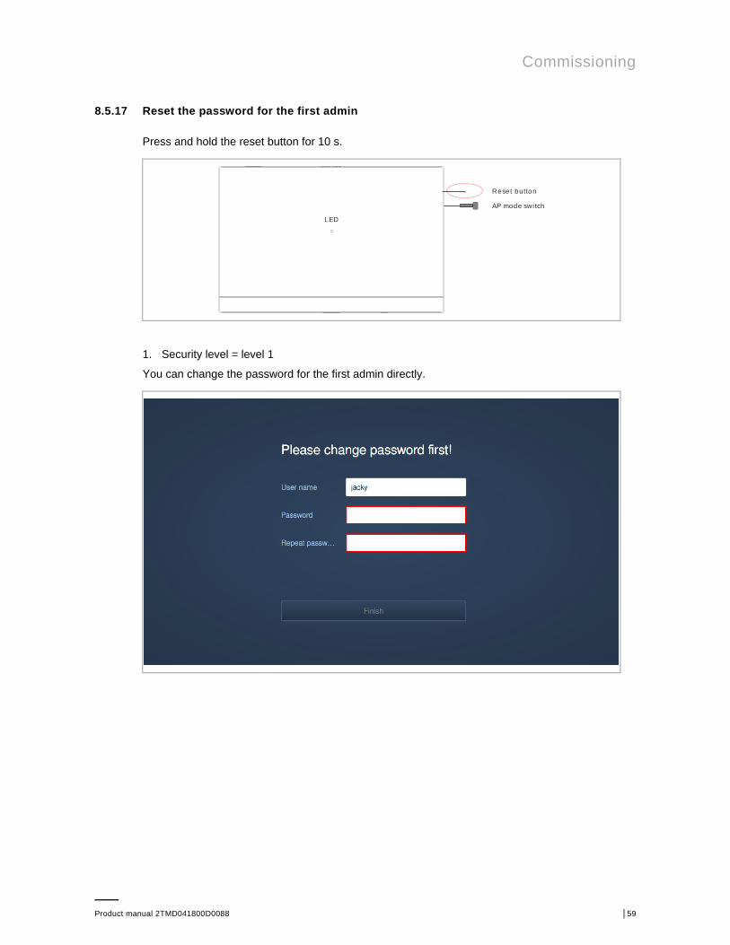
8.5.17 Reset the password for the first admin
Press and hold the reset button for 10 s.
1. Security level = level 1
You can change the password for the first admin directly.
AP mode swi tch
Reset button
LED

Commissioning
Product manual 2TMD041800D0088 │60
2. Security level = level 2
You will receive an email containing the verification code sent by SmartAP.
You need to enter the verification code to continue to change the password for the first admin.

Operation
Product manual 2TMD041800D0088 │61
9 Operation
9.1 Device management
9.1.1 Adding DES devices
NoteOnly a device without a certificate can be added by SmartAP. This device willlose its certificate if its physical address is changed.All the devices need to be powered on before being added.
There are 3 methods to add a DES devices to SmartAP.
Method 1: Search the devices automatically
NoteAll the devices need to be set to the physical address locally before beingadded.
On the configuration screen, click "Door entry system", then click " ", "√" to search alldevices in the same network.
If the device has already been signed by this SmartAP, it will not be signed again.
If the device has already been signed by other SmartAP, it will not be signed and "Sign failed"will be displayed on the "Abnormal devices" screen. Please see the " Abnormal devices"chapter for more details.

Operation
Product manual 2TMD041800D0088 │62
Method 2: Add the devices manually
On the configuration screen, click "Door entry system", "Add device", select the device type(e.g. gate station) and enter the address ID and serial number of the device, then click "Save".

Operation
Product manual 2TMD041800D0088 │63
Method 3: Import the devices from APP
The mobile/tablet (APP) must be in the same network with the router connected to SmartAP.
On the "MAIN MENU" screen of the management software, click " ", a pop-up window willappear.

Operation
Product manual 2TMD041800D0088 │64
On the "Projects" screen of mobile/tablet, swipe the project name to the right, click " ", selecta designated SmartAP and enter the account and password of SmartAP, then click "Log in".
On the configuration screen of SmartAP, a pop-up window shows the importing status.

Operation
Product manual 2TMD041800D0088 │65
9.1.2 Adding VideoControl devices
On the configuration screen, click "Device configuration" to access the corresponding screen.
Please follow the steps below to add an IPC.

Operation
Product manual 2TMD041800D0088 │66
9.1.3 Configure indoor stations
On the configuration screen, click "Door entry system", "Indoor stations", then click an indoorstation to access the settings.

Operation
Product manual 2TMD041800D0088 │67
Basic information
No. Function
1 Device ID
2 Click the icon to return to the previous screen
3 Overview of the indoor station
4 Display the physical address of the indoor station
5 Display the logical address of the indoor station
6 Display the first name and last name of the resident
7 Display the serial number of the indoor station
8 Display the version of the indoor station

Operation
Product manual 2TMD041800D0088 │68
Additional settings
No. Function
1 Set the physical address of the indoor station
2 Set the logic address of the indoor station
3 (1) Duplicate the settings to another indoor station
4 (2) Local firmware update
5 (3) Online firmware update
6 Set the resident data
7 (4) Upload a screensaver image to the indoor station
8 (5) Upload a floorplan to the indoor station
9 (6) Set the language of the indoor station

Operation
Product manual 2TMD041800D0088 │69
(1) Duplicating the settings on another indoor station
Select the indoor stations and the settings to be duplicated, click "Save" to duplicate the settingsfrom the current indoor station to the designated indoor stations.
(2) Local firmware update
Click "Browser" and select the update file and the signature file form local PC, then click "Save"to update the firmware.

Operation
Product manual 2TMD041800D0088 │70
(3) Online firmware update
The router connected by SmartAP must connect to the internet before use.
(4) Upload a screensaver image
Go back to the indoor station, select "Screensaver", click "Browser" and select an image (only.jpg is supported, maximum resolution of the image is 1024 x 600 pixels), click "Save" to sendthis image to the indoor station.

Operation
Product manual 2TMD041800D0088 │71
(5) Upload a floor plan
Click "Browser" to select a floorplan image (only .jpg is supported, maximum resolution of theimage is 1024 x 600 pixels), click "Save" to upload the floorplan.
(6) Setting the language
Select the language from the drop-down list, then click "Save" to save the setting.

Operation
Product manual 2TMD041800D0088 │72
9.1.4 Configure outdoor stations
The following description uses the IP touch 5 outdoor station as an example.
On the configuration screen, click "Door entry system", "Outdoor stations", then click an outdoorstation to access the settings.

Operation
Product manual 2TMD041800D0088 │73
Basic information
No. Function
1 Device ID
2 Click the icon to return to the previous screen
3 Overview of the outdoor station
4 Device type of the outdoor station
5 Display the address of the outdoor station
6 Display the serial number of the outdoor station
7 Display the version of the outdoor station

Operation
Product manual 2TMD041800D0088 │74
Additional settings
No. Funciton
1 Set the physical address for the outdoor station
2(1) Set the calling type for the outdoor station, please see the "Set the calling type" chapter formore details.
3 (2) Set the welcome message for the outdoor station
4(3) Set the door lock time for the outdoor station, please see the "Set the door lock time" chapterfor more details.
5 Set the time synchronization from the management software for the outdoor station
6 Set the lift control function for the outdoor station
7 Set the language for the outdoor station
8 Update the firmware via local PC, please refer to the "Set the indoor station" chapter for moredetails.
9 Update the firmware via the external website, please refer to the "Set the indoor station" chapterfor more details.
10(4) Set the trusted devices for the outdoor station, please see the "Set the trusted devices"chapter for more details.
11(5) Set the welcome screen for the outdoor station, please see the "Set the welcome screen"chapter for more details.
12 (6) Manage the name list, please see the "Manage the name list" chapter for more details.
13 Manage the logic address list, please see the "Manage the logical address list" chapter for moredetails.

Operation
Product manual 2TMD041800D0088 │75
(1) Set the calling type
Tick the "Name list" checkbox, the outdoor station will start a call via the name list.
Untick the "Name list" checkbox, the outdoor station will start a call via the keypad. Next, youcan select "Physical address" or "Logical address" from the drop-down list.
(2) Set the welcome message
Enter the text and click "Save", and the setting will be reflected on the screen of the outdoorstation.

Operation
Product manual 2TMD041800D0088 │76
(3) Set the door lock time
It the default lock type is set to "IP actuator", you need to add the outdoor station to the trustedlist of IP actuators. Please see the "Set the IP actuator" chapter for more details.

Operation
Product manual 2TMD041800D0088 │77
(4) Set the trusted devices
You need to enable the "Trust this management software" function if you want this outdoorstation to unlock in the event of an emergency. Please see the "Emergency unlock" chapter formore details.
Click "Add trusted devices" to add the devices to the outdoor station.
For example, you want the guard unit and the indoor stations to release the lock of this outdoorstation, you need to add them to the trusted list.

Operation
Product manual 2TMD041800D0088 │78
(5) Set the welcome screen
There are 2 functions for setting the welcome screen.
[1] Developer information
Click "Development information", select an image or enter the words. The result will bedisplayed on the screen of the outdoor station.

Operation
Product manual 2TMD041800D0088 │79
[2] Bulletin
Click "Bulletin", "Add bulletin page", "Upload image/logo" to upload a logo or a word. This logoor word will be displayed on the screen of the outdoor station.
A maximum of 3 bulletins can be uploaded. The outdoor station plays the bulletins one by oneand each bulletin is displayed for 10 s.

Operation
Product manual 2TMD041800D0088 │80
(6) Manage the name list
1. Add the name list
There are 2 ways to add the name list
Method 1: Import the name list
Click "Import name list entries" and select the designated indoor stations. Then click "Import".

Operation
Product manual 2TMD041800D0088 │81
Method 2: Add the contacts one by one
Please follow the steps below to add the contact.

Operation
Product manual 2TMD041800D0088 │82
2. Copy the name list to the other outdoor station
Click "Copy name list to other OS", select the destination outdoor stations, and click "Import".
3. Remove the name list
Click "Remove all entries", then click "Continue" to clear the name list.

Operation
Product manual 2TMD041800D0088 │83
9.1.5 Configure guard unit
On the configuration screen, click "Door entry system", "Guard unit", click a guard unit to accessthe settings.

Operation
Product manual 2TMD041800D0088 │84
No. Function
1 Device ID
2 Click the icon to return to the previous screen
3 Overview of the guard unit
4 Device number of the guard unit
5 Display the serial number of the guard unit
6 Display the version of the guard unit
7 Update the firmware via local PC, please refer to the "Set the indoor station" chapter for moredetails.
8 Update the firmware via the external website, please refer to the "Set the indoor station" chapterfor more details.

Operation
Product manual 2TMD041800D0088 │85
9.1.6 Configure IP actuator
On the configuration screen, click "Door entry system", "IP actuator", click an IP actuator toaccess the settings screen.

Operation
Product manual 2TMD041800D0088 │86
No. Function
1 Device ID
2 Click the icon to return to the previous screen
3 Overview of the IP actuator
4 Set device type of the IP actuator (e.g. network IPA, building IPA and private IPA)
5 Display the physical address of the IP actuator
6 Display the serial number of the IP actuator
7 Display the version of the IP actuator
8 (1) Set the lock connected to the IP actuator
9 Update the firmware via local PC, please refer to the "Set the indoor station" chapter for moredetails.
10 Update the firmware via the external website, please refer to the "Set the indoor station" chapterfor more details.
11 (2) Set trusted devices for the IP actuator

Operation
Product manual 2TMD041800D0088 │87
(1) Set the lock connected to the IP actuator

Operation
Product manual 2TMD041800D0088 │88
(2) Set the trusted devices for the IP actuator
You need to enable the "Trust this management software" function if you want this IP actuator tounlock in the event of an emergency. Please see the "Emergency unlock" chapter for moredetails.
Click "Add trusted devices" to add the devices to the IP actuator.
For example, you want the guard unit and the indoor stations to release the lock of this IPactuator, you need to add them to the trusted list.

Operation
Product manual 2TMD041800D0088 │89
Release the IP actuator connected to the outdoor station
If the default lock type of the outdoor station is set to "IP actuator", you need to select an IPactuator.
This outdoor station must be added to the trusted list of IP actuator in advance.

Operation
Product manual 2TMD041800D0088 │90
9.1.7 Configure IPC
On the configuration screen, click "Device configuration" to access the corresponding screen.

Operation
Product manual 2TMD041800D0088 │91
On the "Device configuration" screen, click "IP camera", click an IP camera to access thesettings screen.
No. Description
1 Serial no. and CPU version of the IPC.
2 Click to update the firmware to the latest version.
3 Click to set the IPC step by step.
4 Click to go to the IPC website
5 IP address of the IPC.
6 Authentication information of the IPC.

Operation
Product manual 2TMD041800D0088 │92
More settings of the IPC

Operation
Product manual 2TMD041800D0088 │93
9.1.8 Configure devices in batch
You can configure several devices at the same time.
Fox example, on the "Indoor stations" screen, click " ", click the devices directly or click"select all" to select all the devices, then click "Next".

Operation
Product manual 2TMD041800D0088 │94
You can click "Local firmware update" to update the firmware for these devices.
You can click "Screensaver" to upload a screensaver image for these devices.

Operation
Product manual 2TMD041800D0088 │95
9.1.9 Removing devices
You can remove a device or several devices at the same time.
Fox example, on the "Outdoor stations" screen, click " ", click the devices directly or click"select all" to select all the devices, then click "Delete".

Operation
Product manual 2TMD041800D0088 │96
9.2 User management
9.2.1 Enter the settings
On the configuration screen, click "User management" to access the settings.

Operation
Product manual 2TMD041800D0088 │97
9.2.2 Adding users
On the "User management" screen, follow the steps below:

Operation
Product manual 2TMD041800D0088 │98
9.2.3 Configuring users
On the designated user screen:
No. Description
1 Change first name and last name of the user
2 Change the password of the user
3 Assign the users to the user group or remove the users from the user group.
4 Assign the ID authentications to the user or remove ID authentications from the user.
5 Pair APPs to the user or remove APPs from the user.
6 Assign the locks to the user or remove the locks from the user.

Operation
Product manual 2TMD041800D0088 │99
9.2.4 Removing users
On the designated user screen, click " " to delete the user.

Operation
Product manual 2TMD041800D0088 │100
9.2.5 Adding a user group
You can add a user group so that everyone in the group has the same permissions.
On the "User management" screen, follow the steps below:

Operation
Product manual 2TMD041800D0088 │101
9.2.6 Configuring a user group
On the designated user group screen:
No. Description
1 Assign the users to the user group or remove the users from the user group.
2 Assign the locks to the user group or remove the locks from the user group.

Operation
Product manual 2TMD041800D0088 │102
9.2.7 Removing a user group
On the designated user group screen, click " " to delete the user group.

Operation
Product manual 2TMD041800D0088 │103
9.2.8 Assigning the users to a user group
On the designated user group screen, follow the steps below:

Operation
Product manual 2TMD041800D0088 │104
9.2.9 Removing the users from a user group
On the designated user group screen, follow the steps below:

Operation
Product manual 2TMD041800D0088 │105
9.2.10 Assigning ID authentications to a user
On the designated user screen, follow the steps below:

Operation
Product manual 2TMD041800D0088 │106
Registered ID authentications by card no.
If ID authentications are registered by card no., the "safe mode" function needs to be set to"Disabled" on IP touch 5 outdoor station before use.

Operation
Product manual 2TMD041800D0088 │107
Register by outdoor station (recommend)
Swipe the ID authentications on the outdoor station when the prompt window appears.

Operation
Product manual 2TMD041800D0088 │108
9.2.11 Removing ID authentications from a user
On the designated user screen, follow the steps below:

Operation
Product manual 2TMD041800D0088 │109
9.2.12 Assigning the locks to a user
On the designated user screen, following the steps below, the ID authentications assigned tothis user can release all locks assigned to this user.

Operation
Product manual 2TMD041800D0088 │110
9.2.13 Assigning the locks to a user group
On the designated user group screen, following the steps below, the ID authenticationsassigned to this user can release all locks assigned to this user.

Operation
Product manual 2TMD041800D0088 │111
9.2.14 Removing the locks from a user
On the designated user screen, follow the steps below:

Operation
Product manual 2TMD041800D0088 │112
9.2.15 Removing the locks from a user group
On the designated user screen, following the steps below,

Operation
Product manual 2TMD041800D0088 │113
9.2.16 Pairing APP to a user
1. SmartAP access MyBuildings portal
On the configuration screen, follow the steps below:

Operation
Product manual 2TMD041800D0088 │114
You need to subscribe to the remote service on the MyBuildings Portal before "Refresh license"is executed.

Operation
Product manual 2TMD041800D0088 │115
2. SmartAP access "Pairing devices" screen
On the designated admin screen, click "Pairing devices" and wait for APP operations.

Operation
Product manual 2TMD041800D0088 │116
3. Pairing SmartAP on APP
NoteAPP and SmartAP must not be in the same network.
On the home screen of APP, click "∨" and following the steps below,
SmartAP
Router
APP
Internet3G/4G

Operation
Product manual 2TMD041800D0088 │117
4. SmartAP enter token code

Operation
Product manual 2TMD041800D0088 │118
9.2.17 Removing APP from a user

Operation
Product manual 2TMD041800D0088 │119
9.3 Creating actions
9.3.1 Enter the settings
On the configuration screen, click "Actions" to access the corresponding screen.

Operation
Product manual 2TMD041800D0088 │120
9.3.2 Creating a new action
For example, you want to go on vacation from 2019.10.1 to 2019.10.7 and you need the IPC totake a snapshot when the door fails to release.
Please follow the steps below to create this action.
1. Add precondition
2. Add event

Operation
Product manual 2TMD041800D0088 │121
3. Add actuator
4. Add notification

Operation
Product manual 2TMD041800D0088 │122
9.3.3 Configuring the action
On the actions screen, click " ", change the name or click the icon to enable/disable theaction.
= enable; = disable
Operation
Product manual 2TMD041800D0088 │123
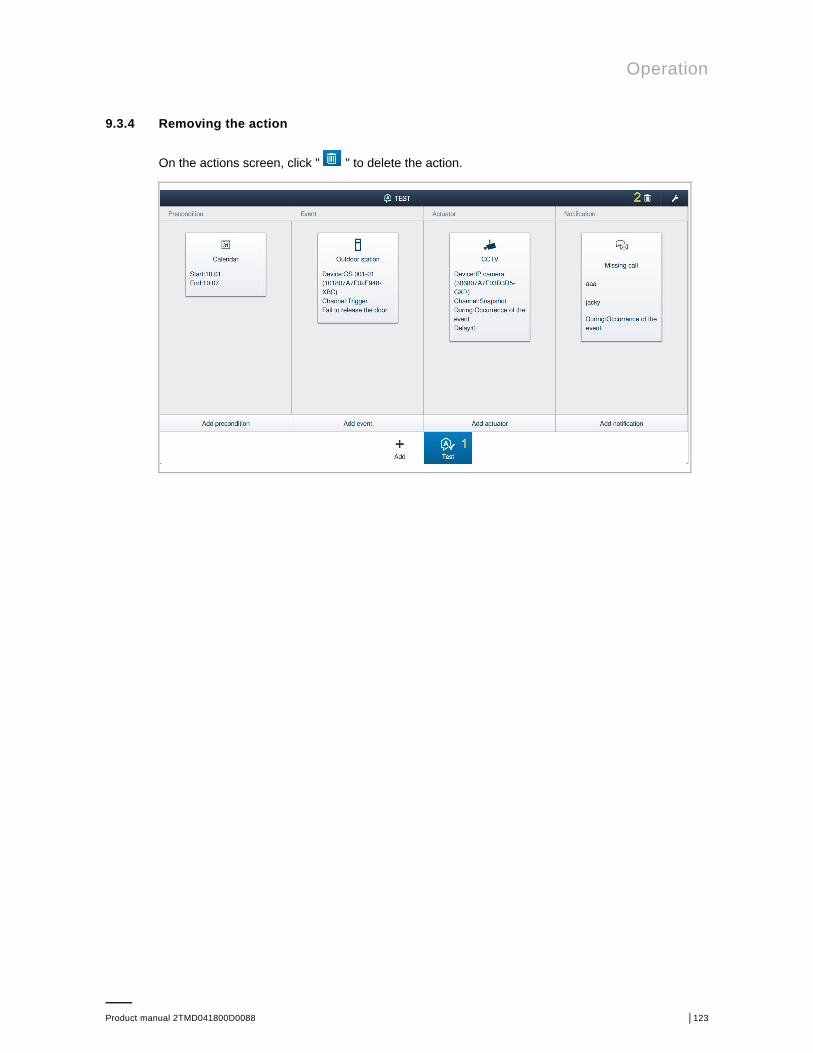
9.3.4 Removing the action
On the actions screen, click " " to delete the action.

Operation
Product manual 2TMD041800D0088 │124
9.4 History
On the configuration screen, click to access the corresponding screen.
A maximum of 16,000 records (including notifications, alarms and logs) are supported.
9.4.1 Notification
A notification can be set when you create an action. When the action is activated, SmartAP willreceive a notification and save this to the history.

Operation
Product manual 2TMD041800D0088 │125
On the "Notification", "Notification" screen, you can view the notifications.
No. Description
1 Number of unread messages
2 Number of total messages
3 Highlighting indicates unread status.
4 Details of the message.
5 Close the view of detailed message.
6 Delete the message.
7 Filter the messages by keywords.
8 Filter the messages by date.
9 Export all messages (including notifications, alarms and logs) to PC.

Operation
Product manual 2TMD041800D0088 │126
9.4.2 Alarm record
On the "Notification", "Alarm" screen, you can view the alarm records.
No. Description
1 Number of unread messages
2 Number of total messages
3 Highlighting indicates unread status.
4 Details of the message.
5 Select a solution between "Processed" and "False alarm".
6 Comment for the alarm.
7 Close the view of detailed message.
8 Delete the message.
9 Filter the messages by keywords.
10 Filter the messages by date or by alarm state.
11 Export all messages (including notifications, alarms and logs) to PC.

Operation
Product manual 2TMD041800D0088 │127
9.4.3 Logs
On the "Notification", "logs" screen, click a log, you can view the call records, unlock recordsand events (e.g. action is triggered or other setting operations).
No. Description
1 Number of unread messages
2 Number of total messages
3 Highlighting indicates unread status.
4 Details of the message.
5 Close the view of detailed message.
6 Delete the message.
7 Filter the messages by keywords.
8 Filter the messages by date or by message type.
9 Export all messages (including notifications, alarms and logs) to PC.

Operation
Product manual 2TMD041800D0088 │128
9.5 Message center
9.5.1 Access "Message center" screen
On the configuration screen, click " " to access the corresponding screen.

Operation
Product manual 2TMD041800D0088 │129
9.5.2 Creating and sending a message
On the "Message center" screen, click "+" to set a receiver, then enter the subject and themessage, click "√" to create and send the message.

Operation
Product manual 2TMD041800D0088 │130
9.5.3 Viewing and replying to a message
On the "Message center" screen, click "Inbox" to view the message received from the indoorstations. You can click on a message and reply to it directly.
A maximum of 1000 messages is supported.
Your reply messages can be viewed in the "Outbox".
A maximum of 100 messages can be supported.

Operation
Product manual 2TMD041800D0088 │131
9.6 Emergency unlock
NoteSmartAP must be added to the trusted list on the outdoor stations, gate stationsand Public IP actuators before this function is used.
On the configuration screen, click "SOS" and enter the user password, click "Unlock all publicdoors" to release all the locks connected to the outdoor stations/gate stations and public IPactuators.

Operation
Product manual 2TMD041800D0088 │132
9.7 Online firmware update
On the configuration screen, click " ", you can find the devices to be updated on a pop-upwindow. Click "Update all" to update all devices.

FCC
Product manual 2TMD041800D0088 │133
10 FCC

Cyber security
Product manual 2TMD041800D0088 │134
11 Cyber security
11.1 Disclaimer
D0401. devices are designed to be connected and to communicate information and data via anetwork interface, which should be connected to a secure network. It is the customer's soleresponsibility to provide and continuously ensure a secure connection between the product andcustomer's network or any other network (as the case may be) and to establish and maintainappropriate measures (including as but not limited to the installation of firewalls, application ofauthentication measures, encryption of data, installation of antivirus programs, etc.) to protectthe D0401. , the network, its system and interfaces against any kind of security breaches,unauthorized access, interference, intrusion, leakage and/or theft of data or information. ABBLtd and its affiliates are not liable for damages and/or losses related to such security breaches,unauthorized access, interference, intrusion, leakage and/or theft of data or information.
Although ABB provides functionality testing on the products and updates that we release, youshould institute your own testing program for any product updates or other major systemupdates (to include but not limited to code changes, configuration file changes, third partysoftware updates or patches, hardware change out, etc.) to ensure that the security measuresthat you have implemented have not been compromised and system functionality in yourenvironment is as expected.
11.2 Performance and service and network performance
Type Value
Ethernet 100 Mbps (148,800 packets/s)
ARP 21 Mbps (31,250 packets/s)
ICMP 20 Mbps (29,800 packets/s)
IP 10 Mbps (14,880 packets/sec)

Cyber security
Product manual 2TMD041800D0088 │135
Port and service
Port Service Purpose
53 TCP DNS
80 TCP HTTP web service
443 TCP HTTPS web service
5222 TCP Service for XMPP client
5280 TCP Service for XMPP HTTP administrator service
5281 TCP Service for XMPP HTTPS administrator service
49152 TCP UPnP
53 UDP DNS
1900 UDP UPnP service
31002 UDP Searched for & managed PC client tools
7000 TCP Private protocol service
10700 TCP Private protocol service (TLS)
8887 TCP Used for upgrading process
7777 TCP Private protocol service
10777 TCP Private protocol service (TLS)
7777 UDP Private protocol service

Cyber security
Product manual 2TMD041800D0088 │136
11.3 Deployment guideline
Please do not install it within a public place and ensure that physical access to the devices isgranted only to trusted person.
It is not recommended to use HTTP (unencrypted data transfer) outside of secure, privatenetworks. Please use HTTPS (encrypted data transfer) when communicating over a publicnetwork. Please note that using HTTPS will result in a warning. This is due to technical reasons.
During commissioning, the RF cylinder and RF repeater need to be added to the one by onefollowing the SmartAP commissioning process, it’s extremely required that the observedindications from RF cylinder and repeater should be confirmed correctly.
The configuration data need to be backed up manually after every Access control systemtopology change, so, the backup configuration can be restored to SmartAP in case ofmisconfiguration.
11.4 Upgrading
The firmware can be uploaded by the webpage, a signature file is also needed to be updatedtogether with firmware file, which is used to verify the authentication and integrity of firmware.
If internet services are available, the device will connect to the MyBuildings server to obtain thenew firmware automatically, but needs to be confirmed by end user every time. Also, forsecurity purpose, the device will automatically download the respective signature file and firstlyverify the authentication and integrity of firmware before updating.
11.5 Backup/restore
Some configurations of devices can be download to locally by webpage, the password isneeded to encrypt the exported configuration data, the configurations include,■ SmartAP device configuration parameters■ User data■ Device data including Access control system device, Door entry system devices and CCTV
system device
When restoring from the backup configured, the exported file needs to be updated to the deviceby webpage, and the respective password used when exporting the configuration is needed.

Cyber security
Product manual 2TMD041800D0088 │137
11.6 Data pursing
In case of quitting from the working system (e.g. replaced by another device, re-install inanother system…), All the data stored in the device need to be purged by the “Restore defaultsetting” in webpage as below,
Login in the web page by admin user account.
On the configuration screen, following the steps below,

Cyber security
Product manual 2TMD041800D0088 │138
11.7 Malware prevention solution
The device D0401. is not susceptible to malware, because custom code cannot be executed onthe system.
The only way to update the software is by firmware upgrading. Only firmware signed by ABBcan be accepted.
11.8 Default passwords and user accounts
In factory default, the device has below passwords or user accounts,■ The password for Wi-Fi Access Point■ The user account for the first commissioning
All the mentioned default passwords and user accounts are mandatory to be changed duringthe first commissioning.
11.9 Password rule
The password for all user accounts need to fulfill below rules,■ Minimum 8 characters■ Must include at least three of these four types: lowercase letters, uppercase letters, digits,
symbols■ Accepted characters: a-z, A-Z, 0-9, space and symbols !"#/()=?@${[]}\,.-_<>|;:'*^~+

Cyber security
Product manual 2TMD041800D0088 │139
11.10 Logging
The device has a logging system which can log some events, which contains,■ Changing settings■ Adding/changing/removing other devices■ Adding/changing/removing user accounts (including information and access rights)■ Updating/patching software firmware■ Accessing to devices, such as unlock, record, snapshot, etc.■ Security attacks, such as tamper alarm, multiple login error, disconnect BLE module from
SmartAP.
The following information and events from devices in Access control system for the loggingpurpose.
Device Information for events
RF Repeater Loss connection with SmartAP event
RF cylinder Battery statusLoss connection from system eventUnlock eventBattery low eventSwipe Card event
Every log information contains time, event source, behavior, and signature.
The device will automatically generate logs and store them when above events occur.
The admin user can log in the webpage, then switch to notification center to manage the logs.

Cyber security
Product manual 2TMD041800D0088 │140
We reserve the right to at all times make technical changes as well as changes to the contentsof this document without prior notice.
The detailed specifications agreed to at the time of ordering apply to all orders. ABB accepts noresponsibility for possible errors or incompleteness in this document.
We reserve all rights to this document and the topics and illustrations contained therein. Thedocument and its contents, or excerpts thereof, must not be reproduced, transmitted or reusedby third parties without prior written consent by ABB.

Contact us NoticeWe reserve the right to at all timesmake technical changes as well aschanges to the contents of thisdocument without prior notice.The detailed specifications agreedupon apply for orders. ABB acceptsno responsibility for possible errorsor incompleteness in this document.
We reserve all rights to thisdocument and the topics andillustrations contained therein. Thedocument and its contents, orextracts thereof, must not bereproduced, transmitted or reusedby third parties without prior writtenconsent by ABB
Err
or! U
se th
e H
ome
tab
to a
pply
#y_
Dec
kbla
tt_D
okum
entT
yp_N
T to
the
text
that
you
wan
t to
appe
ar h
ere.
Erro
r! U
se th
e H
ome
tab
to a
pply
#y_D
eckb
latt
_Sac
hnum
mer
-Dat
um_N
T to
the
text
that
you
wan
t to
appe
ar h
ere.
ABB (United Arab Emirates)Industries(L.L.C)P.O.Box 11070 Dubai-UAET : +971 4 3147 586F : +971 4 3401 541
ABB (Vietnam) Ltd.Km 9 National Highway 1A ,Hoang Liet, Hoang Mai, Hanoi,VietnamT : +84 4 3861 1010F : +84 4 3861 1009
ABB (Turkey) Eletrik San.ASABB Elektrik Sanayi AS. OrganizeSanayi Bolgesi 2 CaddeNo: 16 Y. Dudullu-IstanbulT : +90 216 528 2281F : +90 216 528 2945
ABB (KSA) Electrical IndustriesCo. Ltd.P.O.Box 325841, Riyadh 11371T : +966 1 1484 5600F : +966 1 1206 7609
ABB (Thailand) Ltd.161/1 SG Tower, 1st-4th Floor, SoiMahadlekluang 3, Rajdamri Road,Lumpini, Pathumwan Bangkok10330, ThailandT : +66 2 6651 000F : +66 2 6651 043
ABB (Russia) Ltd.Electrification Smart BuildingsNakhimovskiy prospekt 58117335, Russian Federation,MoscowT: +7 (495) 777-222-0F: +7 (495) 777-222-0
ABB (Korea) Ltd.Oksan Bldg, 10th Fl. 157-33Samsung-dong, Gangnam-gu,135-090, Seoul, KoreaT : +82 2 5283 177F : +82 2 5282 350
ABB Malaysia Sdn BhdBlock A, Level 2, Lot 608, JalanSS13/IK 47500 Subang JayaSelangorT : +60 3 5628 4888F : +60 3 5635 8200
ABB Global Marketing - LebanonDown Town, Beirut, ebanonT : +961 1983 724/5F : +961 1983 723
ABB (Hong Kong) Ltd.3 Dai Hei Street, Tai Po IndustrialEstate, Tai po, Hong KongT : +852 2 9293 912F : +852 2 9293 505
ABB (India) Ltd.Plot No.1, Sector-1B,I.I.E.SIDCUL,Haridwar-249403.IndiaT : +91 133 423 5447F : +91 133 423 5449
ABB Pte. Ltd.2 Ayer Rajah Crescent,Singapore 139935T: + 65 6 7765 711F: + 65 6 7780 222
ABB Australia Pty Ltd.601 Blackburn Road3168, Notting Hill, Victoria,AustraliaT : +61 3 8577 7139F : +61 3 9545 0415
www.abb.com
Approvals and Compliances

Error! Use the Home tab to apply Überschrift 1 to the text that youwant to appear here.
Product manual 2TMD041800D0088 │142
Copyright© 2019 ABBAll rights reserved