30 th october micrscope final
TRANSCRIPT
8/11/2019 30 Th October Micrscope Final
http://slidepdf.com/reader/full/30-th-october-micrscope-final 1/229
1
MICROSCOPES
Author : Dr.P.R.SANJAYA M.D.S.,
Assistant Professor, Faculty of Dentistry
Department of Oral Maxillofacial Pathology & Microbiology
“COLLEGE OF DENTISTRY ”, UNIVERSITY OF HA’IL,
KINGDOM OF SAUDI ARABIA.
email – [email protected]
Co-author : Dr. RhutviVirani B.D.S.,
House Surgeon,
Mahuva, Bhavanagar, Gujarat, India
email- [email protected]

8/11/2019 30 Th October Micrscope Final
http://slidepdf.com/reader/full/30-th-october-micrscope-final 2/229
2
Acknowledgement
I take this opportunity to express my profound gratitude and deepest
regards to The Mother & Sri Aurobindo for guiding me to take up
this topic & complete it on time.
Dr.P.R.Sanjaya
Immeasureable appreciation and deepest gratitude to my parents
and my sister who are all the reasons of my life.
I would like to express the deepest appreciation to Dr.P.R.Sanjaya
M.D.S, sincere, exemplary guidance and encouragement.
Dr.Rhutvi Virani
8/11/2019 30 Th October Micrscope Final
http://slidepdf.com/reader/full/30-th-october-micrscope-final 3/229
3
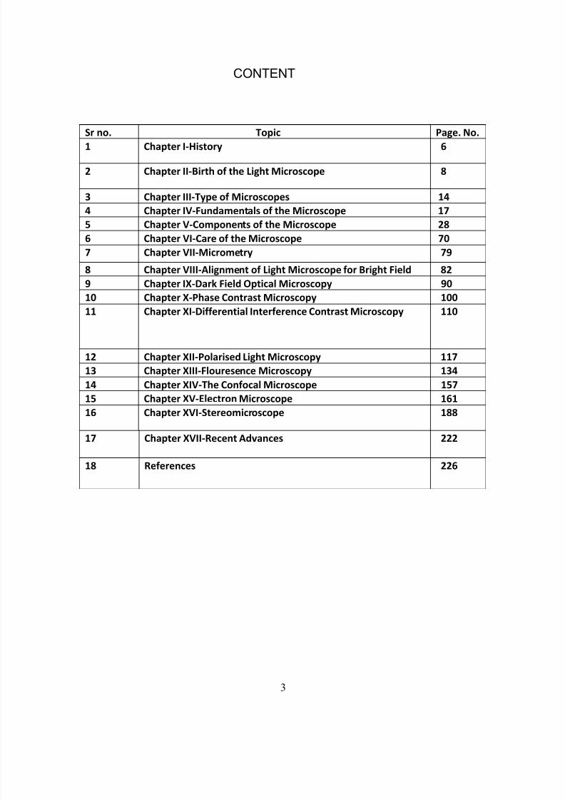
CONTENT
Sr no. Topic Page. No.
1 Chapter I-History 6
2 Chapter II-Birth of the Light Microscope 8
3 Chapter III-Type of Microscopes 14
4 Chapter IV-Fundamentals of the Microscope 17
5 Chapter V-Components of the Microscope 28
6 Chapter VI-Care of the Microscope 70
7 Chapter VII-Micrometry 79
8 Chapter VIII-Alignment of Light Microscope for Bright Field 82
9 Chapter IX-Dark Field Optical Microscopy 90
10 Chapter X-Phase Contrast Microscopy 100
11 Chapter XI-Differential Interference Contrast Microscopy 110
12 Chapter XII-Polarised Light Microscopy 117
13 Chapter XIII-Flouresence Microscopy 134
14 Chapter XIV-The Confocal Microscope 157
15 Chapter XV-Electron Microscope 161
16 Chapter XVI-Stereomicroscope 188
17 Chapter XVII-Recent Advances 222
18 References 226
8/11/2019 30 Th October Micrscope Final
http://slidepdf.com/reader/full/30-th-october-micrscope-final 4/229
4
List of Figure
Sr no. Figures Page no.
1 Robert Hook’s micoscope 10
2 Antony Van Leeuwenhoek 11
3 One of Leeuwenhoek’s microscope 12
4 Size, shape and motility of bacteria by Leeuwenhoek 12
5 Representation of a light ray showing wavelength
and amplitude
18
6 Diminished brightness as light gets further from the source 18
7 Various type of lenses 20
8 Phenomenon of retardation and refraction 22
9 Image formation-Real image , virtual image 23
10 Virtual image formation 24
11 Spherical and chromatic aberration 25
12 Components of microscope 28
13 Praboloid Condenser 30
14 Illumination of microscopic object with or without condenser 31
15 Swing out top lens condenser 35
16 Abbe condenser 36
17 Small microscope 39
18 Critical illumination 41
19 X-Y Translation mechanical stage 47
20 Universal stage 48
21 Body tube 51
22 Condenser centering and condenser adjusting screws 5323 Optical components 54
24 Effect of immersion oil on light rays in compound microscope 63
25 Dry and oil immersion objective lens 63
26 Simple eyepieces 66
27 Size of the real fields 67
28 Ocular micrometer disk 81
29 Inverted light microscope 89
30 Dark ground illumination 92
31 An excellent type of microscope lamp suitable both for ordinay
work and the dark illumination
93
32 DF condenser with lamp attached 93
33 Abbe condenser with dark field stop, Parabolid condenser,
Cardiod condenser
95

8/11/2019 30 Th October Micrscope Final
http://slidepdf.com/reader/full/30-th-october-micrscope-final 5/229
5
34 Stops for dark field illumination 96
35 Spirochetes visualized by dark ground microscopy 99
36 Figure describing optical principle 102
37 Phase contrast microscope accessories 105
38 Phase contrast 106
39 Bright field ,Dark field, Phase contrast 108
40 a)Diffraction at slit b)Ray cross by diffraction at closely
adjacent slits c)Rays cross giving phase conditions for
amplitude differences d)wave peaks interfere in regular
pattern
111
41 Wallaston prism 118
42 Condenser 122
43 Polarizing filter 124
44 Birefringence in polarized light 127
45 Filters in fluorescence microscopy 144
46 Condenser in fluorescence microscopy 14647 Incident fluorescence illumination 148
48 Immuno fluorescence staining for diagnosis of oral blistering
disease
156
49 Electron microscope 166
50 Components of electron microscope 167
51 Transmission electron microscope 172
52 Flow chart illustrating the steps in the preparation of specimen
for diagnosis by electron microscope
173
53 Some examples of specimen gride apparatus for application of
plastic support films
175
54 Electron microscope of a bacteriophage without shadowing
and with shadowing
177
55 Effects of wavelength on resolution 178
56 Bayer pattern 199
57 Image analysis by computers 207

8/11/2019 30 Th October Micrscope Final
http://slidepdf.com/reader/full/30-th-october-micrscope-final 6/229
6
Chapter- I
History
During that historic period known as the Renaissance, after the "dark
middle ages‖, there occurred the inventions of printing, gunpowder
and the mariner's compass, followed by the discovery of America.
Equally remarkable was the invention of the light microscope: an
instrument that enables the human eye, by means of a lens or
combinations of lenses, to observe enlarged images of tiny objects. It
made visible the fascinating details of worlds within worlds.
Long before, in the hazy unrecorded past, someone picked up
a piece of transparent crystal thicker in the middle than at the edges,
looked through it, and discovered that it made things look larger.
They were named lenses because they are shaped like the seeds of
a lentil. Someone also found that such a crystal would focus the sun's
rays and set fire to a piece of parchment or cloth. Magnifiers and
"burning glasses" or "magnifying glasses" are mentioned in the
writings of Seneca and Pliny the Elder, Roman philosophers during
the first century A. D., but apparently they were not used much until
the invention of spectacles, toward the end of the 13th century.

8/11/2019 30 Th October Micrscope Final
http://slidepdf.com/reader/full/30-th-october-micrscope-final 7/229
7
The earliest simple microscope was merely a tube with a plate
for the object at one end, and at the other, a lens which gave a
magnification less than ten diameters -ten times the actual size.
These excited general wonder and were used to view fleas or tiny
creeping things and so were dubbed as ―flea glasses." 7

8/11/2019 30 Th October Micrscope Final
http://slidepdf.com/reader/full/30-th-october-micrscope-final 8/229
8
Chapter- II
Birth of the Light Microscope
Birth of the Light Microscope
The first useful microscope was developed in the Netherlands
between 1590 and 1608. There is almost as much confusion about
the inventor as about the dates. Three different eyeglass makers
have been given credit for the invention. The possible inventors are
Hans Lippershey (who also developed the first real telescope), Hans
Janssen, and his son, Zacharias.
About 1590, two Dutch spectacle makers, Zaccharias Janssen
and Hans, while experimenting with several lenses in a tube,
discovered that nearby objects appeared greatly enlarged. That was
the forerunner of the compound microscope and of the telescope.
Galileo Galilei father of modern physics and astronomy, heard of
these early experiments, worked out the principles of lenses, and
made a much better instrument with a focusing device in 1610. 4
8/11/2019 30 Th October Micrscope Final
http://slidepdf.com/reader/full/30-th-october-micrscope-final 9/229
9
Christian Huygens, another Dutchman, developed a simple 2-
lens ocular system in the late 1600's that was achromatically
corrected and therefore a huge step forward in microscope
development. 7
Robert Hooke made & used a compound microscope in the
1660‘s & described his fascinating explorations of the newly
discovered universe of the microscopic in his classic Micrographia,
published at the request of the royal society in London in 1665 which
contains beautiful drawings based on his microscopic observations.
Robert Hooke re-confirmed Antony van Leeuwenhoek's discoveries
of the existence of tiny living organisms in a drop of water. The first to
record small living organism from plaque in his mouth.
8/11/2019 30 Th October Micrscope Final
http://slidepdf.com/reader/full/30-th-october-micrscope-final 10/229
10
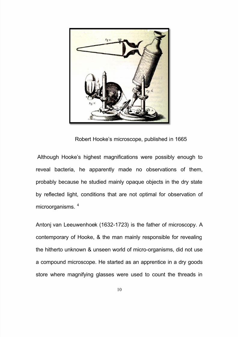
Robert Hooke‘s microscope, published in 1665
Although Hooke‘s highest magnifications were possibly enough to
reveal bacteria, he apparently made no observations of them,
probably because he studied mainly opaque objects in the dry state
by reflected light, conditions that are not optimal for observation of
microorganisms. 4
Antonj van Leeuwenhoek (1632-1723) is the father of microscopy. A
contemporary of Hooke, & the man mainly responsible for revealing
the hitherto unknown & unseen world of micro-organisms, did not use
a compound microscope. He started as an apprentice in a dry goods
store where magnifying glasses were used to count the threads in

8/11/2019 30 Th October Micrscope Final
http://slidepdf.com/reader/full/30-th-october-micrscope-final 11/229
11
cloth. He was not a trained scientist but was self-educated. He taught
himself new methods for grinding and polishing tiny lenses of great
curvature which gave magnifications up to 270 diameters, the finest
known at that time. These led to the building of his microscopes and
the biological discoveries for which he is famous. He was the first to
see and describe bacteria, yeast plants, the teeming life in a drop of
water, and the circulation of blood corpuscles in capillaries. During a
long life he used his lenses to make pioneer studies on an
extraordinary variety of things, both living and non living, and reported
his findings in over a hundred letters to the Royal Society of England
and the French Academy.
Unlike Hooke, Leeuwenhoek made many of his observations by light
transmitted through the object & that the microorganisms were
Antony Van Leeuwenhoek. Afanciful delineation based on a
famous portarait. The picture
shows accurately the size andshape of the first microscopes,
the manner in which they were
used , and the simple lab
apparatus of the “ Father of
bacteriology”
8/11/2019 30 Th October Micrscope Final
http://slidepdf.com/reader/full/30-th-october-micrscope-final 12/229
12
suspended in various fluids, not immobilized or otherwise altered by
drying.4
Later, few major improvements were made until the
middle of the 19th century. Then several European countries began
to manufacture fine optical equipment but none finer than the
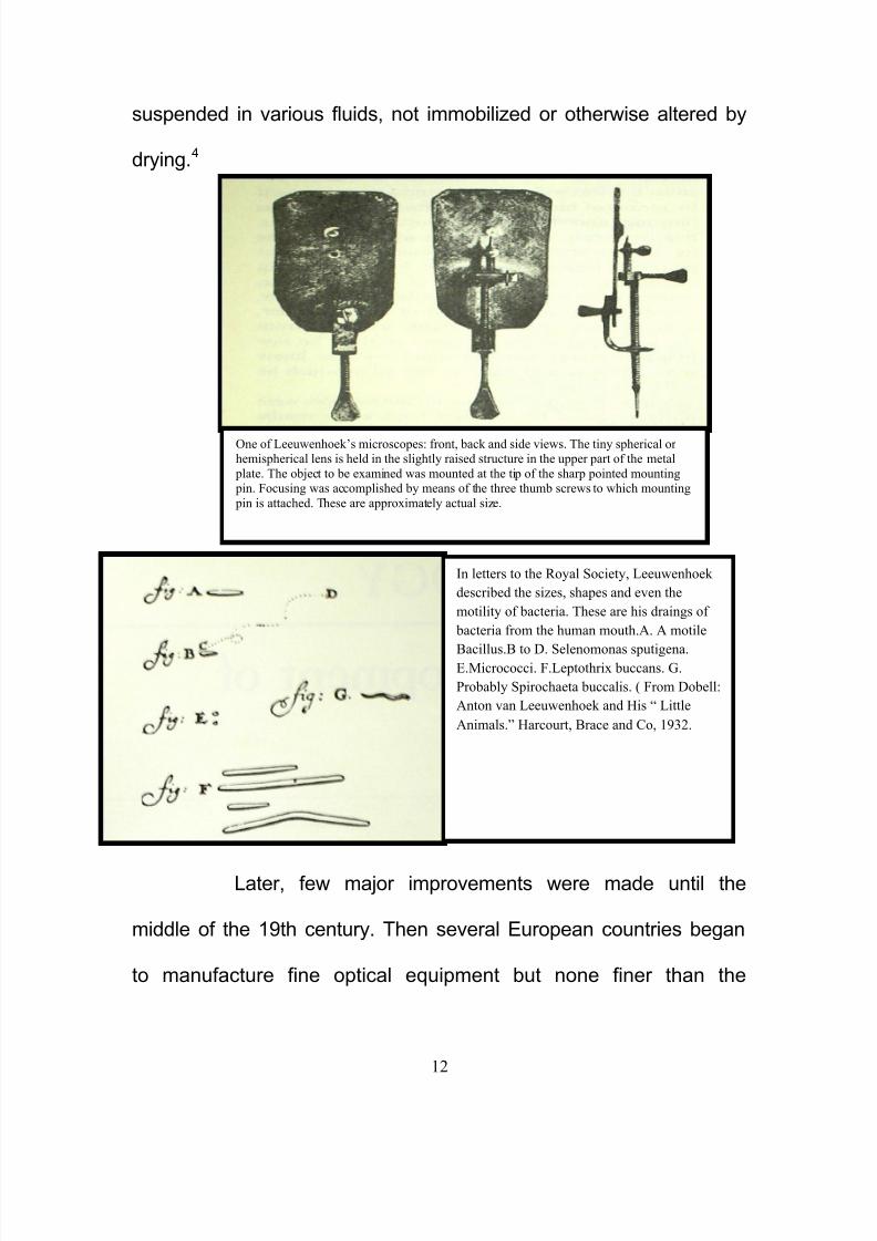
One of Leeuwenhoek’s microscopes: front, back and side views. The tiny spherical orhemispherical lens is held in the slightly raised structure in the upper part of the metal
plate. The object to be examined was mounted at the tip of the sharp pointed mounting pin. Focusing was accomplished by means of the three thumb screws to which mounting
pin is attached. These are approximately actual size.
In letters to the Royal Society, Leeuwenhoek
described the sizes, shapes and even the
motility of bacteria. These are his draings of
bacteria from the human mouth.A. A motile
Bacillus.B to D. Selenomonas sputigena.E.Micrococci. F.Leptothrix buccans. G.
Probably Spirochaeta buccalis. ( From Dobell:
Anton van Leeuwenhoek and His “ Little
Animals.” Harcourt, Brace and Co, 1932.

8/11/2019 30 Th October Micrscope Final
http://slidepdf.com/reader/full/30-th-october-micrscope-final 13/229
13
marvelous instruments built by the American, Charles A. Spencer,
and the industry he founded. Present day instruments, changed but
little, give magnifications up to 1250 diameters with ordinary light and
up to 5000 with blue light. 7

8/11/2019 30 Th October Micrscope Final
http://slidepdf.com/reader/full/30-th-october-micrscope-final 14/229
14
Chapter- III
Types of
Microscopes
Microscopes can largely be separated into two classes, optical
theory microscopes and scanning probe microscopes.
I. Optical theory microscopes (OTM) are microscopes which
function through the optical theory of lenses in order to magnify the
image generated by the passage of a wave through the sample. The
waves used are either electromagnetic in optical microscopes or
electron beams in electron microscopes. The types are the
Compound Light, Stereo, and the electron microscope.
II. In scanning probe microscopy (SPM), a physical probe is
used either in close contact to the sample or nearly touching it. By

8/11/2019 30 Th October Micrscope Final
http://slidepdf.com/reader/full/30-th-october-micrscope-final 15/229
15
rastering the probe across the sample, and by measuring the
interactions between the sharp tip of the probe and the sample, a
micrograph is generated. The exact nature of the interactions
between the probe and the sample determines exactly what kind of
SPM is being used. Because this kind of microscopy relies on the
interactions between the tip and the sample, it generally only
measures information about the surface of the sample.
Some kinds of SPMs are:
Atomic force microscope, Scanning tunneling microscope, Electric
force microscope , Magnetic force microscope (MFM) & Near-field
scanning optical microscope. 7
Optical microscopes, through their use of visible wavelengths of
light, are the simplest and hence most widely used type of
microscope. There are two basic configurations of optical microscope
in use, the simple (one lens) and compound (many lenses).
a) Single-lens Microscope
Consists of one lens only, which produces an enlarged image. It is
much like an ordinary magnifying glass.

8/11/2019 30 Th October Micrscope Final
http://slidepdf.com/reader/full/30-th-october-micrscope-final 16/229
16
b) Compound Microscope
Consists of objective and eyepiece. In its simplest form—as used by
Robert Hooke, for example—the compound microscope would have a
single glass lens of short focal length for the objective, and another
single glass lens for the eyepiece or ocular. Modern microscopes of
this kind are usually more complex, with multiple lens components in
both objective and eyepiece assemblies. 2, 8, 9
Various compound light microscopes are:
Bright field light Microscope (standard compound light
microscope)
Dark-field Microscope
Phase Contrast Microscope
Interference Microscope
Polarizing Microscope
Fluorescence Microscope
Stereomicroscope
Confocal Microscope

8/11/2019 30 Th October Micrscope Final
http://slidepdf.com/reader/full/30-th-october-micrscope-final 17/229
17
Chapter- IV
Fundamentals of
the Light Microscope
Basic optics has been unchanged over 300 years. Light
radiates in all directions from its source. Each ray, unless it is faced
with any interference in its path, travels in a straight line to infinity.
Properties:
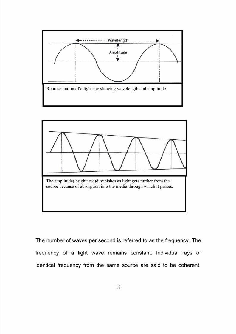
Amplitude refers to the strength of the energy or brightness of
the light. When light travels through any medium, the amplitude
diminishes to a greater or lesser degree depending upon the medium.
The distance between the apex of one wave and the next is the
wavelength and is measured in nanometers. Wavelength determines
color.
8/11/2019 30 Th October Micrscope Final
http://slidepdf.com/reader/full/30-th-october-micrscope-final 18/229
18
The number of waves per second is referred to as the frequency. The
frequency of a light wave remains constant. Individual rays of
identical frequency from the same source are said to be coherent.
Representation of a light ray showing wavelength and amplitude.
The amplitude( brightness)diminishes as light gets further from the
source because of absorption into the media through which it passes.
8/11/2019 30 Th October Micrscope Final
http://slidepdf.com/reader/full/30-th-october-micrscope-final 19/229
19
These rays may combine or interfere with each other in an
observable way. Rays from different sources or of different
frequencies are said to be non-coherent. 1, 5, 10, 11
LENS:
A lens is the name given to a piece of glass or other
transparent material, usually circular, having the 2 surfaces ground &
polished in a specific form in order that rays of light passing through it
shall either converge or diverge.
A lens is called positive when it causes light rays to converge to
form a real image or it is negative in which case light rays passing
through will diverge or scatter & positive or real images will not be
seen. Positive lenses are thicker at the centre than at the periphery,
whereas negative lenses are thinner at the centre. Although the
shapes vary considerably, the characteristics remain the same.
In principle, a real image of any desired magnification can be
obtained from a single positive lens, but in practice this is
cumbersome because of the long lens-image distance. One or more
lenses can be used to magnify the image in stages (total
magnification equaling the product of the magnifications of each
lens). The image formed by one lens constitutes the object for the
8/11/2019 30 Th October Micrscope Final
http://slidepdf.com/reader/full/30-th-october-micrscope-final 20/229
20
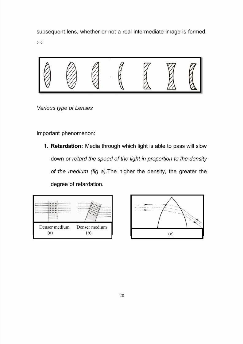
subsequent lens, whether or not a real intermediate image is formed.
5, 6
Various type of Lenses
Important phenomenon:
1. Retardation: Media through which light is able to pass will slow
down or retard the speed of the light in proportion to the density
of the medium (fig a).The higher the density, the greater the
degree of retardation.
Denser medium Denser medium
(a) (b) (c)

8/11/2019 30 Th October Micrscope Final
http://slidepdf.com/reader/full/30-th-october-micrscope-final 21/229
21
2. Refraction: when light enters a sheet of glass at right angles it is
retarded in speed but its direction is unchanged. If the light enters the
glass at any other angle (fig b), a deviation of direction will occur in
addition to the retardation and this is called refraction. 1, 2, 3
A curved lens will exhibit both retardation and refraction (fig c). The
extent of which is governed by:
(a) The angle at which the light strikes the lens-the angle of
incidence.
(b) The density of the glass-its refractive index.
(c) The curvature of the lens.
The angle to which the rays are deviated within the glass or other
transparent medium is called the angle of refraction and the ratio of
the sine values of the angles of incidence (i) and refraction (r) gives a
figure known as the refractive index (RI) of the medium. In simple
words it is the ratio of the velocity of light in air to velocity of light in
that substance.
The greater the RI the higher is the density of the medium. The RI
of most transparent substances is known and is of great value in the
computation and design of lenses. Air has a refractive index of 1.00,
Water- 1.30 and glasses a range of values depending on type but

8/11/2019 30 Th October Micrscope Final
http://slidepdf.com/reader/full/30-th-october-micrscope-final 22/229
22
averaging 1.5.
As a general rule light passing from one medium into a denser
medium is refracted towards the normal. And when passing into a
less dense medium refracted away from the normal. The angle of
incidence may increase to the point where the light emerges parallel
to the surface of the lens. Beyond this angle of incidence, total
internal reflection will occur & no light will pass through.

8/11/2019 30 Th October Micrscope Final
http://slidepdf.com/reader/full/30-th-october-micrscope-final 23/229
23
Focus/image formation:
The word focus originally meant burning place, & was used to
indicate the point at which a lens concentrated the sun‘s rays to form
a sharp image having the power to burn. Parallel rays of light entering
a simple lens are brought together by refraction to a single point. The
principal focus or focal point is where a clear image will be formed of
an object. The distance between the optical center of the lens and the
principal focus is the focal length.
A real image is formed by rays passing
through the lens from the object, and can
be focused on a screen.
A virtual image is viewed through the lens.
8/11/2019 30 Th October Micrscope Final
http://slidepdf.com/reader/full/30-th-october-micrscope-final 24/229
24
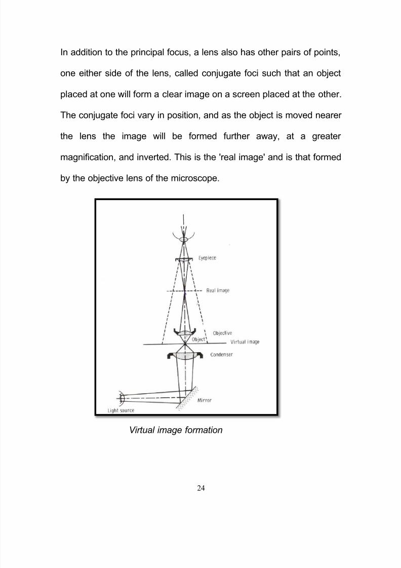
In addition to the principal focus, a lens also has other pairs of points,
one either side of the lens, called conjugate foci such that an object
placed at one will form a clear image on a screen placed at the other.
The conjugate foci vary in position, and as the object is moved nearer
the lens the image will be formed further away, at a greater
magnification, and inverted. This is the 'real image' and is that formed
by the objective lens of the microscope.
Virtual image formation

8/11/2019 30 Th October Micrscope Final
http://slidepdf.com/reader/full/30-th-october-micrscope-final 25/229
25
If the object is placed yet nearer the lens within the principal focus,
the image is formed on the same side as the object, & is enlarged,
the right way up, and cannot be projected onto a screen. This is the
'virtual image' and is that formed by the eyepiece of the microscope.
1, 5, 9, 11, 12
Lens aberrations:
White light is composed of all the spectral colors and on
passing through a simple lens; each wavelength will be refracted to a
different extent, with blue being brought to a shorter focus than red.
This lens defect is chromatic aberration and results in an unsharp
image with colored fringes.
Spherical and chromatic aberration. a) Diagram to illustrate the spherical
aberration of parallel light rays passing through a biconvex lens; b) Diagram to
illustrate the chromatic aberration of a ray of light passing through a biconvex

8/11/2019 30 Th October Micrscope Final
http://slidepdf.com/reader/full/30-th-october-micrscope-final 26/229
8/11/2019 30 Th October Micrscope Final
http://slidepdf.com/reader/full/30-th-october-micrscope-final 27/229
27
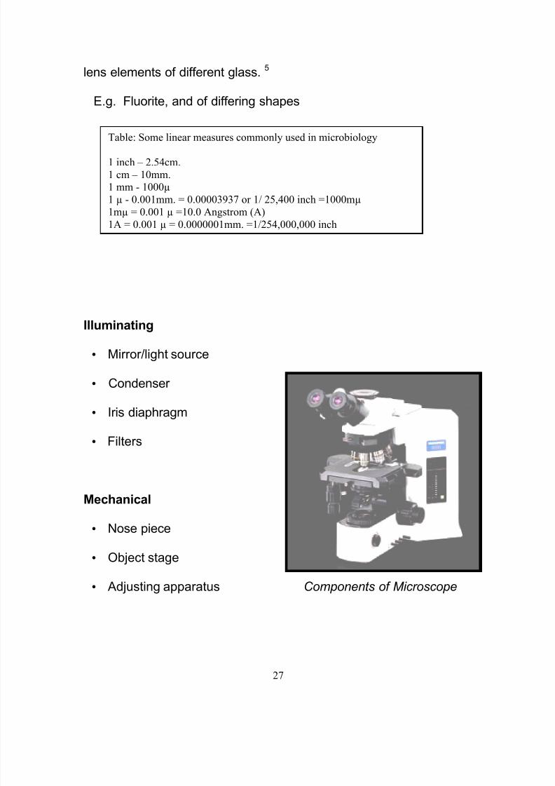
lens elements of different glass. 5
E.g. Fluorite, and of differing shapes
Chapter- V
Componenents of
the Microscope
Illuminating
• Mirror/light source
• Condenser
• Iris diaphragm
• Filters
Mechanical
• Nose piece
• Object stage
• Adjusting apparatus Components of Microscope
Table: Some linear measures commonly used in microbiology
1 inch – 2.54cm.
1 cm – 10mm.1 mm - 1000µ
1 µ - 0.001mm. = 0.00003937 or 1/ 25,400 inch =1000mµ
1mµ = 0.001 µ =10.0 Angstrom (A)
1A = 0.001 µ = 0.0000001mm. =1/254,000,000 inch

8/11/2019 30 Th October Micrscope Final
http://slidepdf.com/reader/full/30-th-october-micrscope-final 28/229
28
Optical
• Objectives
• Eyepieces
• Body tube
1) The microscope proper, incorporating the body tube with the
objective at one end & eyepieces at the other
2) The stand, which includes the supporting, adjusting & illuminating
apparatus 1
Illuminating Apparatus & Illumination:
1) The sub stage:
Below the stage, & usually attached to it, is an adjustable sub stage
which can be moved up & down by a rack & pinion.
The sub stage consists of:
a) the condenser
b) an iris diaphragm
c) a filter carrier
d) a mirror
a) The condenser: Light from the lamp is directed into the first

8/11/2019 30 Th October Micrscope Final
http://slidepdf.com/reader/full/30-th-october-micrscope-final 29/229
29
major optical component, the sub stage condenser, either
directly or by a mirror or prism. The main purpose of the
condenser is to focus or concentrate the available light into the
plane of the object. Within comfortable limits, the more light at
the specimen, the better is the resolution of the image. 1
The substage condenser gathers light from the microscope light
source and concentrates it into a cone of light that illuminates the
specimen with uniform intensity over the entire viewfield. It is critical
that the condenser light cone be properly adjusted to optimize the
intensity and angle of light entering the objective front lens. Each time
Paraboloid condenser
(Bausch and Lomb )

8/11/2019 30 Th October Micrscope Final
http://slidepdf.com/reader/full/30-th-october-micrscope-final 30/229
30
an objective is changed, a corresponding adjustment must be
performed on the substage condenser to provide the proper light
cone for the numerical aperture of the new objective. 1, 5, 11
Illumination of microscopic object without and with substage condenser. The
condenser focuses all the light from the mirror on the object.

8/11/2019 30 Th October Micrscope Final
http://slidepdf.com/reader/full/30-th-october-micrscope-final 31/229
31
Condenser height is controlled by a rack and pinion gear system that
allows the condenser focus to be adjusted for proper illumination of
the specimen. Correct positioning of the condenser with relation to
the cone of illumination and focus is critical to quantitative microscopy
and optimum photomicrography. 10 This is achieved by placing a slide
on the stage & viewing it through the 10X objective. After the radiant
field diaphragm is stopped down, the condenser is moved up /down
until the leaves around the edge of the diaphragm are in sharp focus
& the condenser is centered so that the circle of light is in the center
of the field of view. At this point, the leaves of the radiant field
diaphragm are opened until they just disappear from the field of view.
The condenser aperture diaphragm must now be adjusted. For best
viewing, the aperture should be closed slowly until the sharpest
image is obtained. 14
A critical factor in choosing substage condensers is the
numerical aperture performance that will be necessary to provide an
illumination cone adequate for the objectives. The condenser
numerical aperture should be equal to or slightly less than that of the
highest objective numerical aperture. Therefore, if the highest
magnification objective is an oil-immersion objective with a numerical

8/11/2019 30 Th October Micrscope Final
http://slidepdf.com/reader/full/30-th-october-micrscope-final 32/229

8/11/2019 30 Th October Micrscope Final
http://slidepdf.com/reader/full/30-th-october-micrscope-final 33/229
33
exclusively for either spherical (aplanatic) or chromatic
(achromatic) optical aberrations. Achromatic condensers usually
contain three to four lens elements and are corrected in two
wavelengths (red and blue) for chromatic aberration. Aplanatic
condensers are well corrected for spherical aberration (green
wavelengths) but not for chromatic aberration. The highest level
of correction for optical aberration is incorporated in the aplanatic-
achromatic condenser. This condenser is well corrected for both
chromatic and spherical aberrations and is the condenser of
choice for use in critical color photomicrography with white light. 1,
5
3. When the objective is changed, for example from a 10X to 20X,
the aperture diaphragm of the condenser must also be adjusted to
provide a new light cone that matches the numerical aperture of
the new objective. This is done by turning the knurled knob on the
condensers.

8/11/2019 30 Th October Micrscope Final
http://slidepdf.com/reader/full/30-th-october-micrscope-final 34/229

8/11/2019 30 Th October Micrscope Final
http://slidepdf.com/reader/full/30-th-october-micrscope-final 35/229

8/11/2019 30 Th October Micrscope Final
http://slidepdf.com/reader/full/30-th-october-micrscope-final 36/229
36
an opening of variable size for regulating the illumination. The
intensity of illumination should always, if possible, be reduced by
using light absorbing filters, or a variable resistance, not by closing
the diaphragm & never by rackiserng down the condenser.
Care must be taken to guarantee that the condenser aperture is
opened to the correct position with respect to objective numerical
aperture. When the condenser aperture diaphragm is opened too
wide, stray light generated by refraction of oblique light rays from the
specimen can cause glare and lower the overall contrast. On the
other hand, when the aperture is made too small, the illumination
cone is insufficient to provide adequate resolution and the image is
distorted due to refraction and diffraction from the specimen. 11
C) A filter carrier:
The filter carrier is usually a recessed metal ring, pivoting on a screw
to facilitate the easy removal of filters.

8/11/2019 30 Th October Micrscope Final
http://slidepdf.com/reader/full/30-th-october-micrscope-final 37/229
37
d) The mirror:
The 2 sided mirrors are plane on one side & concave on the other. 1
2) Illumination & source of light:
Early microscopists relied on oil lamps and natural
sunlight to provide an external source of illumination for their primitive
microscopes. Daylight, which was formerly used for illumination
seldom, gives adequate lighting because the weather is too variable.
For this reason electric lamps are used. The objectionable yellowness
of artificial illumination can be eliminated with the use of blue glass
filters.11 Incandescent tungsten-based lamps are the primary
illumination source used in modern microscopes, with the exception
of those intended for fluorescence microscopy investigations. These
lamps are thermal radiators that emit a continuous spectrum of light
extending from about 300 nanometers to upward of 1200-1400
nanometers, with a majority of the wavelength intensity centered in
the 600-1200 nanometer region. Their design, construction, and
operation is simple consisting of an enclosed glass bulb filled with an

8/11/2019 30 Th October Micrscope Final
http://slidepdf.com/reader/full/30-th-october-micrscope-final 38/229
38
inert gas and containing a tungsten wire filament that is energized by
a DC electric current. 7
Small Microscope
Lamp with day lightglass filters
The color temperature and luminance of these lamps varies
with the applied voltage, but average values range from about 2200 K
to 3400 K. When these lamps are used in photomicrography with
color film, the microscopists must use a lamp voltage that produces a
color temperature matching that of the film emulsion, usually
somewhere in the range between 3150 K and 3250 K. Often, the
color temperature must be fine-tuned for photomicrography by

8/11/2019 30 Th October Micrscope Final
http://slidepdf.com/reader/full/30-th-october-micrscope-final 39/229
39
inserting filters into the light path that balance the illumination for the
color temperature of the film emulsion. 15
The source of illumination should be:
- uniformly intense
- should completely flood the back lens of the condenser with light
when the lamp iris
diaphragm is open & make the object appear as though it were self-
luminous
(1) Uniform intensity of illumination is most difficult to obtain since
the solid sources of light-tungsten arc or carbon arc-present
great difficulties if used over long periods. The difficulty is
overcome by using a closely wound filament with a diffusing
screen, although for routine work with a monocular microscope
a 60 watt pearl bulb will suffice. Kohler illumination may be
used.
(2) The source of light should be sufficient to enable its rays when
directed by the plane side of the mirror to flood the back lens of

8/11/2019 30 Th October Micrscope Final
http://slidepdf.com/reader/full/30-th-october-micrscope-final 40/229
40
the condenser uniformly. The high intensity type of lamp has an
optical axis & must be correctly aligned for use, & the distance
from the microscope at which it is used adjusted so that the
lens magnifies the lamp image to the correct size, built-in light
source has been so adjusted. Where separate, the lamp & the
microscope should be connected so that accidental movement
of one or the other will not upset the alignment.
(3) The object will behave as if self-luminous if the opal bulb or the
image of the lamp condenser is focused in the object plane with
the substage condenser.5
There are 2 universally recognized methods for correct illumination.
(1)Nelson method or Critical illumination:
Critical illumination often is used with simple equipment & a
separate light source. The light source should be homogenous & no
amplifying condensers used. The light source is focused in the same
plane as the object, when the object is in focus, by racking the
substage condenser up or down.
8/11/2019 30 Th October Micrscope Final
http://slidepdf.com/reader/full/30-th-october-micrscope-final 41/229
41
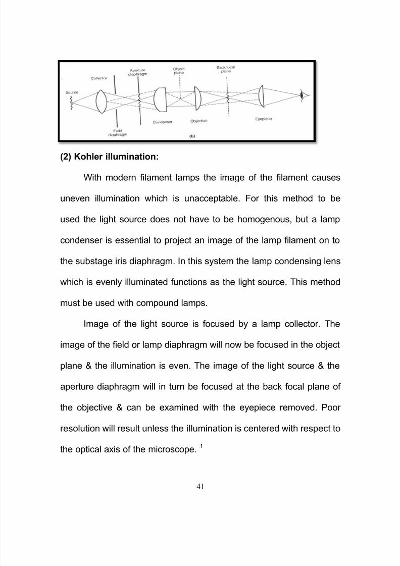
(2) Kohler illumination:
With modern filament lamps the image of the filament causes
uneven illumination which is unacceptable. For this method to be
used the light source does not have to be homogenous, but a lamp
condenser is essential to project an image of the lamp filament on to
the substage iris diaphragm. In this system the lamp condensing lens
which is evenly illuminated functions as the light source. This method
must be used with compound lamps.
Image of the light source is focused by a lamp collector. The
image of the field or lamp diaphragm will now be focused in the object
plane & the illumination is even. The image of the light source & the
aperture diaphragm will in turn be focused at the back focal plane of
the objective & can be examined with the eyepiece removed. Poor
resolution will result unless the illumination is centered with respect to
the optical axis of the microscope. 1

8/11/2019 30 Th October Micrscope Final
http://slidepdf.com/reader/full/30-th-october-micrscope-final 42/229
42
For photography & all the specialized forms of microscopy it is
best to use Kohler illumination, where an image of the light source is
focused by the lamp collector or field lens in the focal plane of the
substage condenser.
Technique:
1. External light source:
1) The lamp should be positioned opposite the microscope, & a
blue daylight filter inserted in the filter carrier to absorb the
excess yellow given by artificial light.
2) Position the lamp so that the light strikes the center of the
mirror, & adjust the mirror so that the light is directed upwards
into the condenser. Modern microscopes have in-built,
condensing lenses & mirrors.
2. Internal source:
3) With a compound lamp focus the condensing lens so that an
image of the source of light is formed on the substage iris
diaphragm; if necessary hold a piece of white paper at this
position so that the image is visible.
8/11/2019 30 Th October Micrscope Final
http://slidepdf.com/reader/full/30-th-october-micrscope-final 43/229
43
4) Focus on an object on the stage & ensure that the field is
evenly illuminated.
5) With the object in focus, rack the substage condenser up or
down until a sharp image of the lamp iris diaphragm appears.
6) Center the image of the field diaphragm using substage
centering controls.
7) Open the field diaphragm until its circle of light is just larger
than the field of view. This reduces glare to the minimum.
8) Remove an eyepiece & adjust the substage iris diaphragm until
two-thirds of the back focal plane of the objective is illuminated.
Replace the eyepiece. The microscope is now ready for use.
For critical microscopy & photomicrography, the field diaphragm may
need to be centered each time the objective is changed. 5, 16
One cardinal rule for the microscopists is always to rack the
objective down near the object before looking through the eyepiece &
then to focus on the object by racking the objective up & away from
the object. This will avoid damaging the object or the front lens of the
objective, & is particularly important when using oil-immersion
objectives, which have very short working distances. This is good

8/11/2019 30 Th October Micrscope Final
http://slidepdf.com/reader/full/30-th-october-micrscope-final 44/229
44
practice even when using objectives with safety retracting front
lenses.
Central & oblique illumination: depends on the direction in
which light enters the microscope. To obtain central illumination the
mirror should be so adjusted that the light from the source is reflected
directly up the tube of the microscope. This is easily done by
removing the ocular & looking down the tube while adjusting the
mirror. The ocular is then replaced & the light reduced as much as
desired by means of the diaphragm.
In simple instruments oblique illumination is obtained by
swinging the mirror to one side so that the light enters the microscope
obliquely. In more complicated instruments it is obtained by means of
a rack & pinion, which move the diaphragm laterally. If the light is
oblique, an object in the center of the field appears to sway from side
to side when the fine adjustment is turned back & forth. The amount
of light admitted is also important which is regulated by the
diaphragm.
To see color & study the outline of an object use central illumination.
To study surface contour, use oblique light of a strength suited to the
color/opacity of the object. 2
8/11/2019 30 Th October Micrscope Final
http://slidepdf.com/reader/full/30-th-october-micrscope-final 45/229
8/11/2019 30 Th October Micrscope Final
http://slidepdf.com/reader/full/30-th-october-micrscope-final 46/229
46
e.g. From 0-80, & the other from 80-110 to avoid confusion in the
readings. Opposite these graduations will be the smaller vernier
scale, marked from 0-10. These 10 graduations, being equal to 9 in
the main scale, enable each of the latter to be subdivided by 10. 5
A stage can be classified according to design and functionality. In the
simplest case, the Plain stage consists of a rectangular or square
design containing several clips to hold the specimen slide. The
circular graduated stage is one of the most versatile and useful
designs for all types of microscopy and photomicrography. These

8/11/2019 30 Th October Micrscope Final
http://slidepdf.com/reader/full/30-th-october-micrscope-final 47/229
47
stages rotate 360°, permitting complete rotation of the samples and
great ease in fine-tuning the composition of view fields for
photomicrography.
Specialized Microscope Stages:
There are a wide variety of microscope stages that are designed for
specific purposes:
a) Inverted Microscope stage
b) Micromanipulators - It is often necessary to manipulate the
specimen while it is being observed under the microscope. This is
the case in many tissue culture and in vitro fertilization experiments
as well as genetic implantation procedures that require close
observation of the sample during the experiment.
c) Universal Stage - This stage permits tilting of a thin specimen at
any angle for measuring the optical structure of a birefringent crystal.
7

8/11/2019 30 Th October Micrscope Final
http://slidepdf.com/reader/full/30-th-october-micrscope-final 48/229
48
2) Body tube:
The body tube is attached to the limb of the microscope
which in turn, is attached to the base either directly or by a hinged
joint. A carrier or nosepiece for a number of objectives is usually fitted
at the lower end of the body tube. It rotates on a central pillar, & is
designated by the number of objectives it carries as double, triple or
quadruple nosepiece. The nose piece should bring each objective
into its correct position i.e., to say, centered on the optical axis, & at
the correct tube length. An increase in magnification is simply a
matter of rotating the nose piece, which is optically better than
changing the eyepiece since a large aperture is being used. The oil-
immersion lenses are, of course, an exception since the body tube
needs to be raised to place oil on the slide. The depth of the nose
piece will affect the tube length & this is generally 18mm in depth, the
actual length of the body tube being only 142mm.
8/11/2019 30 Th October Micrscope Final
http://slidepdf.com/reader/full/30-th-october-micrscope-final 49/229

8/11/2019 30 Th October Micrscope Final
http://slidepdf.com/reader/full/30-th-october-micrscope-final 50/229
50
focused at the lower focal plane of the eyepiece. This is achieved by
using 4 prisms. The lower central prism consists of 2 prisms
cemented together, at the interface of which there is a semi-silvered
surface: this silvering is a special process, fine grains of silver being
deposited so that alternate light rays are differentially treated, one
being reflected to the right & the other passing into the upper prism.
The light rays passing through the semi-silvered surface to the
upper prism travels through a greater thickness of glass than those
that are reflected- having the effect of retarding them-& this is

8/11/2019 30 Th October Micrscope Final
http://slidepdf.com/reader/full/30-th-october-micrscope-final 51/229
51
Body tube
compensated for by making the right hand prism with an extra
thickness of glass. Eyepieces with the prism attached, can be easily
moved together or apart, & the interocular distance adjusted to suit
individual requirements.
With a binocular body on a microscope, the optical tube length
may be increased from 160-240mm, & since the objectives are
corrected for the shorter tube length, a compensating lens is
incorporated to overcome this factor; the lens is also necessary to re-
focus the virtual image for the new tube length. The increase of tube
length also has the effect of increasing magnification, & binocular
attachments may have their magnifying factor engraved on them
which, since the tube is usually increased by one half is x1.5.
Magnification changers may be cited in the body tube above the
objective on a rotating mount. The magnification increase is engraved
at each position, for e.g. X1.25, X1.5. 5
Adjustment apparatus:

8/11/2019 30 Th October Micrscope Final
http://slidepdf.com/reader/full/30-th-october-micrscope-final 52/229
8/11/2019 30 Th October Micrscope Final
http://slidepdf.com/reader/full/30-th-october-micrscope-final 53/229
53
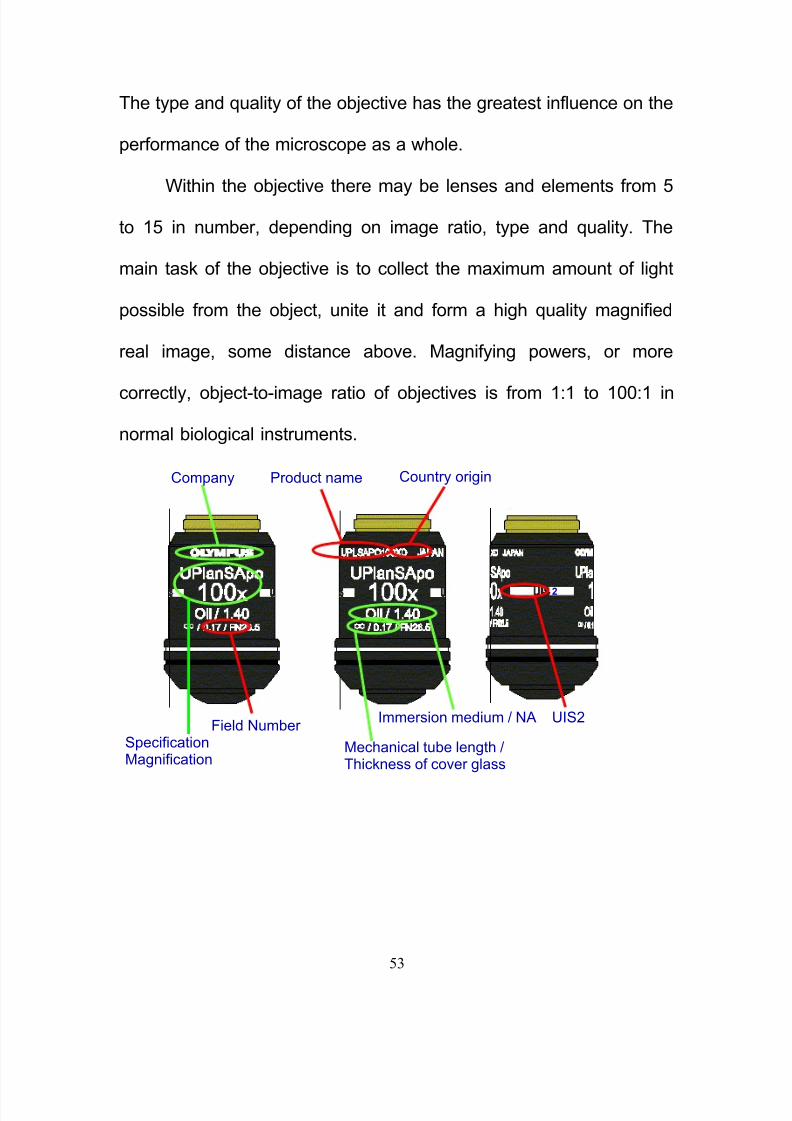
The type and quality of the objective has the greatest influence on the
performance of the microscope as a whole.
Within the objective there may be lenses and elements from 5
to 15 in number, depending on image ratio, type and quality. The
main task of the objective is to collect the maximum amount of light
possible from the object, unite it and form a high quality magnified
real image, some distance above. Magnifying powers, or more
correctly, object-to-image ratio of objectives is from 1:1 to 100:1 in
normal biological instruments.
2
Field NumberUIS2
Country originProduct nameCompany
SpecificationMagnification
Immersion medium / NA
Mechanical tube length /Thickness of cover glass

8/11/2019 30 Th October Micrscope Final
http://slidepdf.com/reader/full/30-th-october-micrscope-final 54/229
54
The ability of an objective to resolve detail is indicated by its
numerical aperture and not by its magnifying power. The numerical
aperture or NA is expressed as a figure, and will be found engraved
on the body of the objective. The figure expresses the product of two
factors and can be calculated from the formula.
NA = n x sin u
Where n=refractive index of the medium between the cover glass
over the object & the front lens of the objective & u=angle between
the optical axis of the lens & the outermost ray which can enter the
front lens.
In practice the maximum NA attainable with a dry objective is 0.95
Water immersion objective-1.30
Oil immersion objective -1.50 1, 5, 13
Magnification: is the increase in the size of the image of an object
.The power of a microscope is described with a number followed by
the letter "X". For example, if through a microscope you can see
something 25 times larger than actual size, its magnification power is
25X. The actual power or magnification of an optical microscope is
the product of the powers of the ocular (eyepiece), usually about 10X,
and the objective lens being used. Dependent on:

8/11/2019 30 Th October Micrscope Final
http://slidepdf.com/reader/full/30-th-october-micrscope-final 55/229
8/11/2019 30 Th October Micrscope Final
http://slidepdf.com/reader/full/30-th-october-micrscope-final 56/229
56
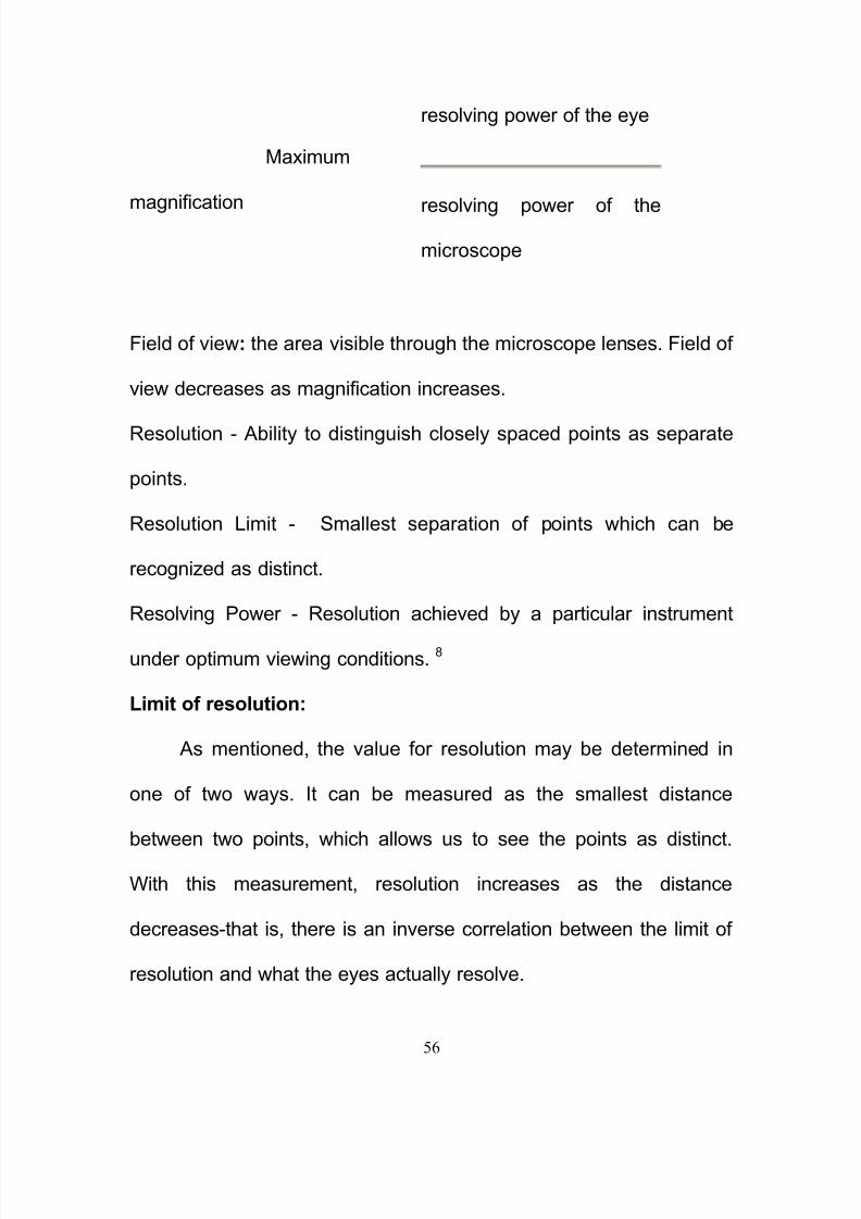
Maximum
magnification
Field of view: the area visible through the microscope lenses. Field of
view decreases as magnification increases.
Resolution - Ability to distinguish closely spaced points as separate
points.
Resolution Limit - Smallest separation of points which can be
recognized as distinct.
Resolving Power - Resolution achieved by a particular instrument
under optimum viewing conditions. 8
Limit of resolution:
As mentioned, the value for resolution may be determined in
one of two ways. It can be measured as the smallest distance
between two points, which allows us to see the points as distinct.
With this measurement, resolution increases as the distance
decreases-that is, there is an inverse correlation between the limit of
resolution and what the eyes actually resolve.
resolving power of the eye
resolving power of the
microscope

8/11/2019 30 Th October Micrscope Final
http://slidepdf.com/reader/full/30-th-october-micrscope-final 57/229
57
0.61 X λ
Limit of Resolution = ---------------
NA
To change this to a direct correlation, one need only use the
reciprocal of the limit of resolution. Resolution is the reciprocal of the
limit of resolution. For measures of resolution then, as the value
increases, resolution increases. Consequently, most microscopists
today use resolution rather than limit of resolution to measure the
quality of their lenses.
The reason for a dichotomy between magnification and
resolution is the ability of the human eye to distinguish two points. It is
necessary that two points are about 0.1 mm apart when held 10" from
the face in order for us to detect them as two objects. If they are
closer than 0.1 mm, we will perceive them as a single object. If two
objects are 0.01 mm apart, we can not detect them unless we
magnify an image of them by 10X.
Unfortunately, a lens can magnify an image without increasing
the resolution. Several artifacts can be inherent in the lens design

8/11/2019 30 Th October Micrscope Final
http://slidepdf.com/reader/full/30-th-october-micrscope-final 58/229
58
which causes the objects to become blurry at the edges. Thus, even
though they can be made to appear 0.1 mm apart, the edges are so
blurry that we lose the ability to see them as two objects.
Resolution can be increased in three ways:
The easiest method is to increase the angle of light incidence, by
altering the position and/or design of the sub stage condenser.
Second, the refractive index can be maximized by using specially
manufactured lenses, and by controlling the medium through
which the light travels, i.e. using immersion oil with lenses
designed for this purpose.
The third method is to decrease the wavelength of light used.
For practical purposes, the wavelength has a larger effect on
resolution than either changes in the angle of incidence or the
refractive index. For maximum resolution, all three properties must be
optimized. 1, 5, 7
In practice, magnification can be increased in 2 ways:
Using a high power objective: As a rule this is the best way,
because resolving power is also increased, but it is often
undesirable because of the shorter working distance & because

8/11/2019 30 Th October Micrscope Final
http://slidepdf.com/reader/full/30-th-october-micrscope-final 59/229
59
the higher power objective often gives greater magnification
than is desired or cuts down the size of the real field too much.
Using a high power ocular: This is the simplest method. It has,
however, certain limitations. When an ocular that is too strong
is used, there results a hazy image in which no structural detail
is seen clearly (Empty magnification).
Types of objectives:
The objective lens is, at its simplest, a very high powered
magnifying glass i.e. a lens with a very short focal length. This is
brought very close to the specimen being examined so that the light
from the specimen comes to a focus about 160 mm inside the
microscope tube. This creates an enlarged image of the subject. This
image is inverted and can be seen by removing the eyepiece and
placing a piece of tracing paper over the end of the tube. By careful
focusing a rather dim image of the specimen, much enlarged can be
seen. It is this real image that is viewed by the eyepiece lens that
provides further enlargement.

8/11/2019 30 Th October Micrscope Final
http://slidepdf.com/reader/full/30-th-october-micrscope-final 60/229
60
All objectives are engraved with the information needed to obtain
their maximum performance as well as any possible limitations. Such
an engraving might read:
Plan 40/0.65
160/0.17
with indication that it is a planachromat; 40X magnification at a tube
length of 160mm, has a NA of 0.65 & should be used with a
coverglass of 0.170±0.01mm in thickness.
Achromatic Objectives:
It is the most commonly used objective. Modern well corrected lenses
of this type are more than adequate for routine microscopy
Apochromatic Objectives:
They are used in conjunction with highly corrected aplanatic or
achromatic condenser & compensating eyepieces. Must always be
used for photomicrography.
Flourite Objective (Neoflour):
Flourite/semi apochromatic objectives have flourite incorporated into
the lens system to give better colour correction. They represent a
quality of image mid way between that of achromat & apochromat.
Plan objectives:

8/11/2019 30 Th October Micrscope Final
http://slidepdf.com/reader/full/30-th-october-micrscope-final 61/229
61
Many type of PLAN objectives, such as Plan Apochromat / Plan
Fluorite / Plan Achromat. They are used to give a perfectly flat field,
with the whole field in focus at the same time. Planapochromat
objectives are mainly used for photomicrography. Planachromats are
used for cytology screening.
Polarizing Objective:
They are strain-free objectives & are used for polarizing microscope.
Phase Objectives:
They contain a phase plate for use in phase-contrast microscopy.
They have a designated phase with a number which refers to the
matching annulus.
Dry type objective:
It is the most commonly used objective with a range of magnification
from low to high power (1.25-100X) . 1, 5
Oil immersion objective:
When the rays of light emerge from the upper surface of the
condenser, some are reflected beyond the scope of the objective &
lost. Others are reflected away from the underside of the glass slide
on which the objective is mounted, & lost. Others are refracted &
reflected from its upper surface. Others are lost by refraction &

8/11/2019 30 Th October Micrscope Final
http://slidepdf.com/reader/full/30-th-october-micrscope-final 62/229
62
reflection in the object & at the surface of the objective lens. A
considerable part of these various losses & distortion of the image
can be prevented by eliminating the optical effect of these surfaces.
This is done by placing a clear, colorless fluid (immersion oil), having
the same refractive index as glass, between condenser & slide &
between slide & objective lens. For high power microscopy the
objective lens is made for oil-immersion. Immersion oil in effect can
increase the NA of a lens because it brings in more light rays. 4, 13
Water immersion objective:
– For brain slice specimen
– Use water as medium
Effect of immersion oil on light rays in
compound microscope. Light rays enter the
condenser from below. Light ray A shows
path of light if oil is placed only between
slide and objective lens (the common
practice).Broken line A shows loss of rays
A if oil is placed between slide and
objective, as above, and also between slide
and condenser(the practice in dark field
microscopy). Broken line B shows loss of
rays B if oil is not used. Arrows R,R,R
show additional loss of light by reflection
fromtop and bottom surfaces of slide if oil
8/11/2019 30 Th October Micrscope Final
http://slidepdf.com/reader/full/30-th-october-micrscope-final 63/229
63
Cover glass thickness:
Most objectives are designed for use with a cover glass
protecting the object. Oil immersion objectives do not have cover
glass restrictions since they will have the same RI as the immersion
oil. The cover glass thickness is only important if high power dry
objectives are being used. A figure giving the correct cover glass
thickness should be found engraved on the objective between 0.11-
0.22mm, usually this is 0.17 mm. 1, 5
Eyepiece:
Eyepieces are the final stage in the optical path of the
microscope. Their function is to magnify the image formed by the
objective within the body tube and present the eye with a virtual

8/11/2019 30 Th October Micrscope Final
http://slidepdf.com/reader/full/30-th-october-micrscope-final 64/229
64
image, apparently in the plane of the object being observed. Usually
this is an optical distance of 250 mm from the eye. In most
microscopes, the eyepiece is a compound lens, which is made of two
lenses one near the front and one near the back of the eyepiece tube
forming an air separated couplet. In many designs, the virtual image
comes to a focus between the two lenses of the eyepiece, the first
lens bringing the real image to a focus and the second lens enabling
the eye to focus on the now virtual image.
In all microscopes the image is viewed with the eyes focused at
infinity. Headaches and tired eyes after using a microscope are
usually signs that the eye is being forced to focus at a close distance
rather than at infinity.They may be used to correct residual errors in
the objective lenses & may be either under corrected or
overcorrected.
Undercorrected: when a blue ray of light will be refracted to a greater
degree than the red, this can be identified by the blue fringe that is
seen around the edge of the field diaphragm
Overcorrected: when the reverse is the case & an orange fringe may
be seen at the edge of the field diaphragm.
8/11/2019 30 Th October Micrscope Final
http://slidepdf.com/reader/full/30-th-october-micrscope-final 65/229
65
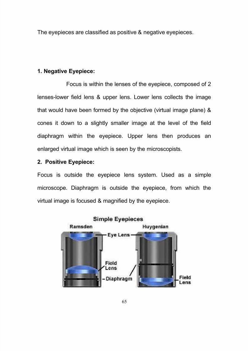
The eyepieces are classified as positive & negative eyepieces.
1. Negative Eyepiece:
Focus is within the lenses of the eyepiece, composed of 2
lenses-lower field lens & upper lens. Lower lens collects the image
that would have been formed by the objective (virtual image plane) &
cones it down to a slightly smaller image at the level of the field
diaphragm within the eyepiece. Upper lens then produces an
enlarged virtual image which is seen by the microscopists.
2. Positive Eyepiece:
Focus is outside the eyepiece lens system. Used as a simple
microscope. Diaphragm is outside the eyepiece, from which the
virtual image is focused & magnified by the eyepiece.

8/11/2019 30 Th October Micrscope Final
http://slidepdf.com/reader/full/30-th-october-micrscope-final 66/229
66
Types of Eyepieces available:
Huygenian Eyepiece:
They were originally designed by Huygens for the telescope. They
are most commonly used eyepieces. They are Negative, Undercorrected &
are best suited for use with achromatic objectives.
Ramsden Eyepiece:
These are positive oculars. Most of the compensated eyepieces are
of Ramsden type, having doublet or triplet lenses instead of single
lens. It is preferred for micrometer eyepieces as they impart less
distortion to scales.
Wide Field Eyepieces:
These lenses give a large field of view. They are valuable in
biological laboratory.
Size of the “real fields”
(actual areas seen through themicroscope) with variousobjectives and occulars and
the tube length of 160mm.The
size differs slightly with
microscopes of differentmakes.

8/11/2019 30 Th October Micrscope Final
http://slidepdf.com/reader/full/30-th-october-micrscope-final 67/229
67
High-Eye point Oculars:
They were introduced primarily for spectacle wearers. With normal
eyepieces, the distance between the top of the eyepiece & the exit
pupil is so small as to prevent the wearing of the glasses, but the high
eye point of these special oculars make this possible. It is advised
that the rubber guards supplied with such eyepieces be used to
prevent the scratching of the spectacle lens.
Compensating Eyepieces:
They were originally intended for use with apochromatic objectives
only but now are recommended for use with all modern objectives.
English speaking countries mark them ‗comp‘ & the German by the
letter ‗K‘.5
Extensions of the optical microscope:
Most modern instruments provide simple solutions for micro-
photography and image recording electronically. However such
capabilities are not always present and the more experienced
microscopist will, in many cases, still prefer a hand drawn image

8/11/2019 30 Th October Micrscope Final
http://slidepdf.com/reader/full/30-th-october-micrscope-final 68/229
68
rather than a photograph. This is because a microscopist with
knowledge of the subject can accurately convert a three dimensional
image into a precise two dimensional drawing . In a photgraph or
other image capture system however, only one thin plane is ever in
good focus.
Creating careful and accurate micrographs requires a
microscopical technique using a monocular eyepiece. It is essential
that both eyes are open and that the eye that is not observing down
the microscope is instead concentrated on a sheet of paper on the
bench besides the microscope. With practice, and without moving the
head or eyes, it is possible to accurately record the observed details
by tracing round the observed shapes by simultaneously "seeing" the
pencil point in the microscopical image. Practising this technique also
establishes good general microscopical technique. It is always least
tiring to observe with the microscope focussed so that the image is
seen at infinity and with both eyes open at all times. 7
8/11/2019 30 Th October Micrscope Final
http://slidepdf.com/reader/full/30-th-october-micrscope-final 69/229
69
Chapter- VI
Care of the Microscope
Microscopes get less attention than they deserve
because any deterioration is usually so gradual as to pass unnoticed
in day-today use. There are, in fact, only two places where sudden
catastrophic failure may occur. One of these is the lamp bulb which
will burn out with no warning. The other is the nosepiece clip which
breaks after long use, usually giving warning by gradually losing its
springiness so that the nosepiece rotates too freely. Whenever a
8/11/2019 30 Th October Micrscope Final
http://slidepdf.com/reader/full/30-th-october-micrscope-final 70/229
70
microscope is in constant use, the user is strongly recommended to
keep a spare lamp bulb and also a nosepiece clip with suitable
screws ready to hand.
When the performance deteriorates gradually, three possibilities
should be considered. These are: dirty lenses, misalignment so that
the optical axis is not straight and incorrect focusing of the light
source. If these faults are sought and corrected periodically, the effort
will be amply repaid by the optical and aesthetic rewards obtained. 12
Everything on a good quality microscope is unbelievably
expensive, so be careful.
Hold a microscope firmly by the stand, only. Never grab it by the
eyepiece holder, for example.
Hold the plug (not the cable) when unplugging the illuminator.
Since bulbs are expensive, and have a limited life, turn the
illuminator off when done.
Always make sure the stage and lenses are clean before putting
away the microscope.
Never use a paper towel, a kimwipe, or any material other than
good quality lens tissue or a cotton swab (must be 100% natural
cotton) to clean an optical surface. Be gentle. May use an

8/11/2019 30 Th October Micrscope Final
http://slidepdf.com/reader/full/30-th-october-micrscope-final 71/229

8/11/2019 30 Th October Micrscope Final
http://slidepdf.com/reader/full/30-th-october-micrscope-final 72/229
72
deposits at this site may include immersion oil and occasionally a thin
film or streak of mounting medium (balsam or D. P. X.) from a newly
mounted slide; these transparent films may not be obvious until the
lens is viewed with a magnifying glass in a good light.
The top of the condenser may collect dust and also minute
chips of glass; these are broken from the edges and corners of slides
by stage clips that are allowed to spring sharply into place. Because
of the likelihood that these glass chips will scratch the lens surface,
the condenser must be cleaned by blowing or gentle brushing before
being rubbed with even the softest tissue. The mirror collects dust. It
may be cleaned with no special precautions except when a surface-
aluminized or surface-silvered mirror is provided, as it may be when
the illumination is built in. In this case, special care is needed to avoid
scratching the delicate metallic coating; gentle mopping with tissues
soaked in alcohol and then with dry tissue is the most that is
permissible.
When cleaning any of the optical components of the micro-
scope, it is essential to avoid all forms of fibrous or starchy textiles; a
soft camel-hair brush will remove dust particles, and a piece of lens
tissue or well-washed soft and thin cotton may be used to remove
8/11/2019 30 Th October Micrscope Final
http://slidepdf.com/reader/full/30-th-october-micrscope-final 73/229
73
grease. The surface may be moistened by-condensation from the
breath, or by clean water. Obstinate grease marks can usually be
removed successfully with diluted alcohol; stronger grease solvents
(e.g. xylene) should be handled with caution since they may soften
the cement in which the lenses are mounted.
Sometimes the microscope image is marred because dust
particles appear to be superimposed on it. As an aid to the location of
this dust, the best plan is to proceed as follows. First move the slide
to make sure that the dust is not there. Secondly rotate the eyepiece;
if the dust particles rotate they are on one of the eyepiece lenses.
Thirdly, if the dust is still undetected, alter the focus of the condenser;
if the image of the dust vanishes it is on the condenser, mirror, or
lamp; if it persists it is in the objective. Fourthly: if the mirror is
adjustable, move it slightly; if the dust moves it is on the lamp or the
mirror itself. More rarely the microscope image appears to have a
fibre or thread superimposed upon it. This can usually be located in
the way already described, but occasionally the fibre will be found to
be caught in the edge of an iris diaphragm so that it projects into the
path of light. Gently opening and closing the iris diaphragms will
readily locate such a fibre.

8/11/2019 30 Th October Micrscope Final
http://slidepdf.com/reader/full/30-th-october-micrscope-final 74/229
74
When cleaning the optical system of a microscope, the com-
ponents should be dismantled as little as possible. It is better to
return an unsatisfactory component to the supplier, or to call for the
services of an expert, than to venture into unfamiliar territory. Such
items as high-power objectives and, above all, binocular prism
systems should not be dismantled by the inexperienced. Dust or
opacity in a compound lens or prism is very rarely due to a fault
between the various glass elements. When, however, attention to the
accessible surfaces does not remove the dust or opacity, the defect is
probably attributable to crystallization of the cement between two
elements, or the growth of fungi within the lens. Faults like these can
only be remedied by an expert.
The mechanical parts of the microscope also need to be
cleaned from time to time, but once again it is better not to dismantle
unfamiliar components. In general, it is comparatively easy to
dismantle and reassemble nineteenth-century and early twentieth-
century microscopes, since these were assembled by hand from
blocks of solid brass. Many modern microscopes, however, include
mechanical components that were assembled with the use of special
tools. Most modern iris diaphragms, for instance, should be

8/11/2019 30 Th October Micrscope Final
http://slidepdf.com/reader/full/30-th-october-micrscope-final 75/229
75
dismantled only by the expert. If the microscope is protected against
dust when not in use, it will need cleaning and lubricating only
occasionally. A piece of rag soaked in xylene is useful for removing
dirty oil, but all the xylene must be wiped away before new oil is
applied.
The parts requiring lubrication are: bearings that house rotating
axis (e.g. the coarse adjustment spindle), pivots (e.g. stage clips and
many fine adjustments), and slides (e.g. those permitting the
condenser mounting to slide up and down on the microscope stand).
The actual teeth of cogwheels, or rack and pinion mechanisms, do
not need lubricant since this collects dust and grit which is likely to
grind away the surfaces of the teeth until they fail to mesh firmly with
each other. In choosing a lubricant, the best plan is to follow the
instructions of the microscope manufacturer. In general we have
preferred to use light machine oil at frequent intervals. The alternative
is thin grease; this is particularly popular for old microscopes, where it
may confer a temporary improvement in performance by reducing the
play in the worn mechanical stage or other moving part. Grease does
not need to be renewed as often as oil; this sometimes produces a
false sense of security so that the microscope receives no attention

8/11/2019 30 Th October Micrscope Final
http://slidepdf.com/reader/full/30-th-october-micrscope-final 76/229
76
for a long time. It is then found that every trace of grease has been
squeezed out of the working parts and has dried up in gummy brown
nodules along their edges. 12
Daily cleaning routine
The microscope should be dusted daily, & the outer surface of
the lenses of objectives polished with lens tissue or cotton wool.
The top lens of the eyepiece should be polished to remove dust
or fingermarks, & the microscope set up for correct illumination.
Rotation of the eyepiece will show if any dust is still present, in
which case the eyepiece may need to be dismantled & both
lenses cleaned.
The substage condenser & the mirror are cleaned in a similar
manner: dust on the condenser will be apparent when this is
racked up & down, since it will come in & out of focus.
A little attention to cleaning the microscope daily will, by the
removal of chemically-active & sharp pieces of grit & foreign
matter, prolong the life of the instrument & make the weekly
cleaning task a short & simple one.

8/11/2019 30 Th October Micrscope Final
http://slidepdf.com/reader/full/30-th-october-micrscope-final 77/229

8/11/2019 30 Th October Micrscope Final
http://slidepdf.com/reader/full/30-th-october-micrscope-final 78/229
78
Chapter- VII
Micrometry
The standard unit of measurement in microscopy is a
micrometer, which is a 0.001mm. To measure microscopic object an
eyepiece micrometer scale is used inconjunction with a stage
micrometer. The eyepiece micrometer scale is usually a disc on
which is engraved an arbitrary scale. This is placed inside the
huygenian eyepiece, resting on the field stop. Eyepiece micrometers
may be purchased with the scale permanently in position; these are
usually Kellner eyepieces which have a focal plane below their

8/11/2019 30 Th October Micrscope Final
http://slidepdf.com/reader/full/30-th-october-micrscope-final 79/229
79
bottom lens. They give a sharp image of the scale & have a greater
eye clearance; they are an advantage for general work if spectacles
are worn. The stage micrometer consists of a 3X1 inch slide on which
a millimeter scale is engraved in 1/10 & 1/100 graduations.5
Graticule - a network of fine lines, dots, cross hairs, or wires in the
focal plane of the eyepiece of an optical instrument. Most "whole
world" graticules are laid out from -180 to 180 degrees Longitude and
from -70 to 70 degrees Latitude in spacing of 10 degrees.
The Difference between Graticules and Grids
Graticules are always expressed in geographic coordinates (latitude
and longitude) while grids are expressed in the native X and Y
coordinates of the coordinate system of the component. For
components using the Latitude / Longitude "non-projection", both
graticules and grids will appear as a grid of horizontal and vertical
straight lines. In projected coordinate systems, graticules will be
created as curved lines (if necessary) to parallel the curved form of
meridians of longitude or parallels of latitude in the projection. Grids,
however, will always appear as a grid of horizontal and vertical
straight lines. 12
An object may be measured by the following method:

8/11/2019 30 Th October Micrscope Final
http://slidepdf.com/reader/full/30-th-october-micrscope-final 80/229
80
-insert a micrometer eyepiece scale & place the stage micrometer on
the stage
-select the objective to be used when measuring the object, & focus
on the stage micrometer scale
-determine the number of divisions of the eyepiece scale equal to an
exact number of divisions of the stage micrometer scale
-Remove the stage micrometer, focus on the object to be measured &
determine the number of eyepiece divisions exactly covered by the
object.
Micrometer eyepiece with a movable scale
Calculate the size of the object as follows, assuming that 100
eyepiece divisions were equal to 10 small stage divisions, & that the
diameter of the object was exactly covered by 12 eyepiece divisions. 5
100 stage divisions=1mm=1000µm
100 eyepiece divisions=10 stage divisions

8/11/2019 30 Th October Micrscope Final
http://slidepdf.com/reader/full/30-th-october-micrscope-final 81/229
81
Therefore 100 eyepiece divisions=100µm
Therefore 1 eyepiece division=1µm
Therefore 12 eyepiece divisions=12µm
The diameter of the object, therefore, was 12 µm.
Chapter- VIII
Alignment of Light Microscope for Bright Field
Turn on transformer for tungsten light source and set at appropriate
level
Set condenser setting to bright field
Center lamp
Place centering disk (paper, plastic, frosted glass or centering
aid) over opening in stand below stage

8/11/2019 30 Th October Micrscope Final
http://slidepdf.com/reader/full/30-th-october-micrscope-final 82/229

8/11/2019 30 Th October Micrscope Final
http://slidepdf.com/reader/full/30-th-october-micrscope-final 83/229
83
Adjust sub stage condenser with centering screws until image
of field diaphragm is centered
Open field diaphragm until it is just outside field of view
Check focus of lamp filament (when aligning after bulb change)
Open sub stage aperture diaphragm
Remove eyepiece
Loosen lamp lock screw on lamp housing
Rotate bulb and move back and forth until illumination is most
intense and even
Adjust sub stage aperture diaphragm
Adjustment will vary for specimen
Start with aperture wide open
Close diaphragm slowly until image has best contrast
Use neutral density filter(s) or adjust transformer rheostat to adjust
brightness of illumination during viewing. 1, 5, 7, 16
Bright Field Microscopy Applications:
Bright field microscopy is best suited to viewing stained or naturally
pigmented specimens such as stained prepared slides of tissue

8/11/2019 30 Th October Micrscope Final
http://slidepdf.com/reader/full/30-th-october-micrscope-final 84/229

8/11/2019 30 Th October Micrscope Final
http://slidepdf.com/reader/full/30-th-october-micrscope-final 85/229
85
The interpretation of ground sections under the optical
microscope is complicated by both the thickness and crystalline
nature of the material. Often the material on the slide is 150 microns
thick and this means that there is a superimposition of features. The
presence or incorporation of cellular and organic material in the
mineralized tissue will alter the refractive index and consequently
influence its optical appearance.
The mineralized tissues do not take up stain as readily as the
soft tissues and the view under the optical microscope depends upon
the differences in refractive indices between the various structures.
To view these sections its better to use less light in the microscope by
closing down the diaphragm controls and not by reducing the lamp
intensity. 1
Advantages:
Simplicity of setup with only basic equipment required.
No sample preparation required, allowing viewing of live cells.
Limitations :
The technique can only image dark or strongly refracting objects
effectively.

8/11/2019 30 Th October Micrscope Final
http://slidepdf.com/reader/full/30-th-october-micrscope-final 86/229
86
Compound optical microscopes are limited in their ability to resolve
fine details by the properties of light and the refractive materials
used to manufacture lenses (to approximately 0.2 micrometre).
Out of focus light from points outside the focal plane reduces
image clarity.
Live cells in particular generally lack sufficient contrast to be
studied successfully, internal structures of the cell are colourless
and transparent. The most common way to increase contrast is to
stain the different structures with selective dyes, but this involves
killing and fixing the sample. Staining may also introduce artifacts,
apparent structural details that are caused by the processing of
the specimen and are thus not a legitimate feature of the
specimen.
Optical microscopes have a focal point, either chosen or fixed,
where the image is clear. This covers a two-dimensional area only.
A single optical image cannot capture all the details of a three-
dimensional shape in focus. 1, 5, 6, 12
Oblique Illumination:
This uses sideways (oblique) illumination; either by covering
part of the light source to give asymmetric lighting, or even an

8/11/2019 30 Th October Micrscope Final
http://slidepdf.com/reader/full/30-th-october-micrscope-final 87/229
87
external light source being shone sideways in the sample. This gives
the image a 3D appearance and can highlight otherwise invisible
features. 17
Reflected Light Microscope:
In brightfield reflected light microscopy, proper use of the two
variable diaphragms: the aperture iris diaphragm (closer to the light
source) and the field iris diaphragm (closer to the specimen), enable
the use of the highly desirable Kohler illumination. These diaphragms
are in the opposite of their respective positions in transmitted light,
the aperture diaphragm now being closer to the light source. In these
reflected light systems, the objective serves a dual function: on the
way down as a matching well-corrected condenser properly aligned;
on the way up as an image-forming objective in the customary role of
an objective projecting the image-carrying rays toward the eyepiece.
In a transmitted light system, changing the objective requires an
adjustment in the numerical aperture of the condenser to match that
of the new objective. However, in reflected light, the objective and
condenser numerical apertures change simultaneously with a new

8/11/2019 30 Th October Micrscope Final
http://slidepdf.com/reader/full/30-th-october-micrscope-final 88/229
88
objective. Conjugate planes are similar to those described for
transmitted light, with images of the light source being formed in the
back focal plane of the objective and within the aperture diaphragm
iris opening. This serves to reduce the complexity of establishing the
conditions of Koehler illumination in reflected light microscopy. 7
Inverted Light Microscope:
To observe cultured cell, living cell & Laboratory dish.

8/11/2019 30 Th October Micrscope Final
http://slidepdf.com/reader/full/30-th-october-micrscope-final 89/229
89
Chapter- IX
Dark Field Optical Microscopy

8/11/2019 30 Th October Micrscope Final
http://slidepdf.com/reader/full/30-th-october-micrscope-final 90/229
90
So far the microscope has been shown as suitable for the
examination of stained preparations. Staining aids the formation of
images by absorbing part of the light (some of the wavelengths) and
producing an image of amplitude differences and color. Occasions
arise when it is preferable or essential that unstained sections or
living cells are examined. Such specimens and their components
have refractive indices close to that of the medium in which they are
suspended and are thus difficult to see by bright-field techniques due
to their lack of contrast.
Stars can be readily observed at night primarily because of the
stark contrast between their faint light and the black sky. Yet stars are
shining both night and day, but they are invisible during the day
because the overwhelming brightness of the sun "blots out" the faint
light from the stars, rendering them invisible. During a total solar
eclipse, the moon moves between the Earth and the Sun blocking out
the light of the Sun and the stars can now be seen even though it is
daytime. In short, the visibility of the faint star light is enormously
enhanced against a dark background.
This principle is applied in darkfield (also called darkground)
microscopy, a simple and popular method for making unstained

8/11/2019 30 Th October Micrscope Final
http://slidepdf.com/reader/full/30-th-october-micrscope-final 91/229
91
transparent specimens clearly visible. Such objects often have
refractive indices very close in value to that of their surroundings and
are difficult to image in conventional brightfield microscopy. Dark-
ground microscopy overcomes these problems by preventing direct
light from entering the front of the objective and the only light
gathered is that reflected or diffracted by structures within the
specimen. This causes the specimen to appear as a bright image on
a dark background, the contrast being reversed and increased.
In this microscope, oblique light is achieved by using a modified
or special condenser to form a hollow cone of direct light which will
pass through the specimen but outside the objective. Dark-ground
condensers may be for either dry, low-power objectives, or for high

8/11/2019 30 Th October Micrscope Final
http://slidepdf.com/reader/full/30-th-october-micrscope-final 92/229
92
power oil immersion objectives. Whichever is used, the
objective must have a lower NA than the condenser.
In order to obtain this condition it is sometimes necessary to
use objectives with built in iris diaphragm or, more simply, by
inserting a funnel stop into the objective. Perfect centering of the
condenser is essential, & with the oil immersion systems it is
necessary to put oil between the condenser & the object slide in
addition to the oil between the slide & the objective. As only light
diffracted by the specimen will enter the objective, a high intensity
light source is required. 1, 5
An excellent type of microscope lamp suitable both for ordinary work
& the darkfield illumination.

8/11/2019 30 Th October Micrscope Final
http://slidepdf.com/reader/full/30-th-october-micrscope-final 93/229
93
DF condenser with lamp attached.
Objectives & Condensers:
Low-power objectives work at some distance from the object &
therefore darkground illumination is obtained by simply inserting a
small circle of black paper in the filter carrier.

8/11/2019 30 Th October Micrscope Final
http://slidepdf.com/reader/full/30-th-october-micrscope-final 94/229
94
High-power objectives, having a much shorter working distance
require a special condenser which will accurately focus a hollow cone
of light at an acute angle. This angle is so acute that if oil is not used
between the condenser & slide the light rays are reflected back into
the condenser (total internal reflection). Immersion oil must be used
between the object & the objective to ensure that maximum amount
of reflected light from the object enters the objective. To get the best
results the condenser must be accurately centered & focused.
Because of the very acute angle of the light required, very few
darkground condensers can be used with an objective having a
numerical aperture more than 1.0. The most convenient is 2mm
objective having a NA 1.3 which is incorporating an iris diaphragm,
since this can be closed just sufficiently to stop any direct light.
The Fixed-focus type of darkground condenser is most
common, but this can only be used with extra-thin glass slides &
coverslips. Focusing darkground condensers are available which will
allow a variety of slides & coverslips to be used.
Most bright field microscopes can be converted for dark-ground
work by using simple patch stops, made of black paper, placed on top
of the condenser lens or suspended in the filter holder.

8/11/2019 30 Th October Micrscope Final
http://slidepdf.com/reader/full/30-th-october-micrscope-final 95/229
95
The actual size will vary, depending upon several factors including
the proximity of the stop with respect to the condenser aperture
diaphragm, the numerical aperture of both the objective and the
condenser, the degree of aberration correction for the condenser, and
the field number of the eyepiece. Also important in determining the
stop size is the diameter of the condenser back lens, the
magnification power of the eyepiece (smaller magnifications require
slightly larger stops), and the type of mounting medium. Stop size
varies proportionally to the refractive index of the mounting medium:
higher refractive index requires a larger stop. A dry mount will also
need a smaller stop than an aqueous suspension. 1, 5, 7, 11, 16
Parabolid Condenser Cardioid
Condenser
Abbe condenser with DarkField sto

8/11/2019 30 Th October Micrscope Final
http://slidepdf.com/reader/full/30-th-october-micrscope-final 96/229
96
Rheinberg illumination is a special variant of dark field
illumination and is named after its inventor, Julius Rheinberg. In this
variant transparent colored filters are inserted just before the
condenser so that light rays at high aperture are differently colored
than those at low aperture, using a dark color for the center disc and
a contrasting lighter color for the periphery. This system reduces the
glare of conventional dark ground and reveals the specimen in, say,
red on a blue background.
Variable intensity dark ground is obtained by making the Rheinberg
discs from polarizing filters, the center being orientated at right angles
to the periphery. This allows good photomicrography 1, 5
Requirements:
Thin slides and cover glasses should be used and the
preparation must be free of hairs, dirt and bubbles.
Dark field microscopy uses a carefully aligned light source to
minimise the quantity of directly transmitted light (ie.

8/11/2019 30 Th October Micrscope Final
http://slidepdf.com/reader/full/30-th-october-micrscope-final 97/229
97
unscattered light) entering the image, and only collected light
scattered by the sample. This is done by confining the
illumination to a ring of light.
For DF various adjustments must be much more accurate than for a
BF. The most frequent causes of failure to secure a satisfactory DF
with brilliantly lighted objects that appear to be self-luminous are:
1. Use of an objective with too wide an aperture. When the regular
oil immersion is used, its aperture must be reduced by means
of the stop provided by the makers.
2. Failure to focus & to center the condenser accurately. Very
slight readjustments of the condenser/mirror after the
examination is begun may remedy matters, provided the slide is
not too thick to permit accurate focusing.
3. Inclusion of air bubbles in the preparation/in the oil above/below
the slide. It is generally necessary to remove the oil & apply
again.
4. Inclusion of too many microscopic objects in the field. This may
be remedied by diluting the fluid to be examined/by reducing
the thickness of the preparation by means of slight pressure on
the coverglass. 2

8/11/2019 30 Th October Micrscope Final
http://slidepdf.com/reader/full/30-th-october-micrscope-final 98/229
98
5. Applications:
Dark-ground illumination is particularly useful for spirochetes,
flagellates, cell suspensions, flow cell techniques, parasites and auto
radiographic grain counting, and is commonly used in fluorescence
microscopy. Many small structures are more easily visualized by
dark-ground techniques due to increased contrast, although
resolution may be inferior to bright-field microscopy.
Spirochetes visualized by dark ground microscopy.
Spirochetes are much thinner than most bacterial cells (
approximately 0.1mm in diameter compared with 1mm
for Escheria coli), but they appear larger when viewed
by dark ground illumination.

8/11/2019 30 Th October Micrscope Final
http://slidepdf.com/reader/full/30-th-october-micrscope-final 99/229
99
Advantages:
Clearly shows even transparent objects in the sample.
Simplicity of setup with only basic equipment required.
No sample preparation required, allowing viewing of live cells.
Limitations:
The main limitation of dark field microscopy is the low light levels
seen in the final image. This means the sample must be very strongly
illuminated, and can cause damage to the sample.
Low apparent resolution due the blur of out of focus objects.
Chapter- X
Phase Contrast Microscopy
Phase contrast is a widely used technique that shows
differences in refractive index as difference in contrast. Unstained
and living biological specimens have little contrast with their

8/11/2019 30 Th October Micrscope Final
http://slidepdf.com/reader/full/30-th-october-micrscope-final 100/229

8/11/2019 30 Th October Micrscope Final
http://slidepdf.com/reader/full/30-th-october-micrscope-final 101/229
101
different RIs, through which light acquires small phase differences
and these form the image. Unstained cells are similar to diffraction
gratings as their contents also differ very slightly in RI.

8/11/2019 30 Th October Micrscope Final
http://slidepdf.com/reader/full/30-th-october-micrscope-final 102/229
102
Figure describing optical principle
Two rays of light from the same source, having the same frequency,
are said to be coherent, and when recombined, will double in
amplitude or brightness if they are in phase with each other
( constructive interference). If however they are out of phase with
each other, destructive interference will occur.
Suppose a ray is 1/2 lambda out of phase with the other, then
they cancel each other out. This is maximum destructive interference
and no light is seen, resulting in maximum contrast. However if one
ray is brighter than the other (increased amplitude) and is still 1/2
lambda out of phase then the difference in amplitude can be seen
while maintaining maximum interference. This last position is that
which occurs in the phase contrast microscope.
To achieve phase contrast the microscope requires
-Intense light source is required to be set up for Kohler illumination
-Modified objectives and condenser
-And relies on the specimen retarding light by between 1/8-1/4λ 1, 2, 3,
4, 5, 9
The microscope equipment for phase contrast

8/11/2019 30 Th October Micrscope Final
http://slidepdf.com/reader/full/30-th-october-micrscope-final 103/229
103
The microscope condenser usually carries a series of annular
diaphragms made of opaque glass, with a clear narrow ring to
produce a controlled hollow cone of light. The required ring diameter
increases with the numerical aperture, i.e. high apertures require the
maximum diameter (e.g. 0.9 in air or 1.3 with oil immersion).
Phase contrast requires special objectives which are equipped
with a phase ring near the pupil. They are easy to recognize by the
green inscription ―Ph1‖, ―Ph2‖ or ―Ph3‖. Each objective requires a
different size of annulus, an image of which is formed by the con-
denser in the back focal plane (BFP) of the objective as a bright ring
of light. The objective is modified by a phase plate which is placed at
its BFP.
A positive phase plate consists of a clear glass disc with
circular trough etched in it to half the depth of the disc. The disc in the
objective has special optical properties: it first of all reduces the direct
light in intensity, but more importantly, it creates an artificial phase
difference of about a quarter wavelength i.e., The light passing
through the trough has a phase difference of 1/4λ compared to the
rest of the plate. The trough also contains a neutral-density light-

8/11/2019 30 Th October Micrscope Final
http://slidepdf.com/reader/full/30-th-october-micrscope-final 104/229
104
absorbing material to reduce the brightness of the direct rays, which
would otherwise obscure the contrast obtained.
The phase stops must be centered once after they have been
inserted in the condenser so that the image of the phase stop in the
objective pupil corresponds exactly with the position of the phase ring
in the beam path. Centering is performed using two small wrenches
on the turret disk of the condenser. Again, look into the objective pupil
and bring the bright image of the condenser phase stop into
coincidence with the phase ring of the objective. This is clearly shown
in the figure below: On the left side, the phase stop of the condenser
(bright) is not aligned, while it is in perfect congruence with the phase
ring of the objective on the right

8/11/2019 30 Th October Micrscope Final
http://slidepdf.com/reader/full/30-th-october-micrscope-final 105/229
105
Phase contrast microscope accessories: Rotatable turret type
condenser, a set of 4 objectives with phase altering patterns in the
rear focal planes, a green filter, & a centering telescope.
To be particularly precise, a centering telescope for the setting
can be used. This small accessory looks like an eyepiece and is also
inserted into the tube instead of an eyepiece. When it is focused on
the pupil of the objective, the aperture diaphragm and the phase
stops can be conveniently controlled. 1, 3, 5, 9
Each combination of annulus and objective phase plate will
require centeration. When the hollow cone of direct light from the
annulus enters the specimen some will pass through unaltered while
some rays will be retarded (or diffracted) by approximately1/4λ. The
image of an object in phase contrast can be influenced by
appropriately selecting the retardation of the main beam through the
phase ring in the objective.
The direct light will mostly pass through the trough in the phase
plate while the diffracted rays pass through the thicker clear glass
and are further retarded. The total retardation of the diffracted rays is
now1/2λ and interference will occur when they are recombined with

8/11/2019 30 Th October Micrscope Final
http://slidepdf.com/reader/full/30-th-october-micrscope-final 106/229
106
the direct light. Thus an image of contrast is achieved revealing even
small details within unstained cells. 1
Light waves A (solid lines), are transmitted through the object & pass
through the phase-altering ring on the phase plate. At this point they
acquire a one-quarter-wave-length advance over light waves, B
(broken lines), which do not pass through the object but are partly
diffracted around it. Waves (B) do not pass through the phase altering
ring on the phase plate. The resultant interference/resonance effects

8/11/2019 30 Th October Micrscope Final
http://slidepdf.com/reader/full/30-th-october-micrscope-final 107/229
107
of the 2 portions of the light form the final image. Altered phase
relations in the illuminating rays, induced by otherwise invisible
elements in the specimen, are translated into brightness difference
(contrast) by the phase-altering plate; hence, phase contrast.
Depending on the retardation selected, objects with a higher
refractive index than their surroundings appear either brighter or
darker than their surroundings. This is also called ―positive‖ or
―negative‖ phase contrast. Today, ―positive‖ phase contrast is
standard, where the darkness of objects increases with their
refractive index. This simulates absorption to the observer‘s eye in
areas where a higher refractive index becomes locally effective. 4
Advantages:
This is a quick and efficient way of examining unstained
paraffin, resin and frozen sections.
Studying living cells and their behavior.
In the interference microscope the retarded rays are entirely
separated from the direct or reference rays allowing improved

8/11/2019 30 Th October Micrscope Final
http://slidepdf.com/reader/full/30-th-october-micrscope-final 108/229
108
image contrast, color graduation and quantitative
measurements of phase change (or 'optical path difference'),
refractive index, dry mass of cells (optical weighing) and section
thickness. 1, 5, 9,10
Central eosinophil & RBCs as seen in 3 different microscopes:
Bright Field Dark Field Phase Contrast
Limitations:
Contrast is excellent; however it is not for use with thick objects.
In phase contrast microscopy, the specimen retards some light
rays with respect to those which pass through the surrounding
medium. The resulting interference of these rays provides

8/11/2019 30 Th October Micrscope Final
http://slidepdf.com/reader/full/30-th-october-micrscope-final 109/229
109
image contrast but with an artifact called the 'phase halo' which
obscures detail.
Chapter- XI
Differential Interference Contrast Microscopy
Differences in optical density will show up as differences in
relief, which is manifested in the "visibility" of boundaries, and

8/11/2019 30 Th October Micrscope Final
http://slidepdf.com/reader/full/30-th-october-micrscope-final 110/229

8/11/2019 30 Th October Micrscope Final
http://slidepdf.com/reader/full/30-th-october-micrscope-final 111/229
111
by side form two fans of rays which will cross and if coherent, will
observably 'interfere'. If each ray is regarded as a wave it can be
seen that phase conditions of increased amplitude and extinction are
bound to occur at points where the waves cross and interfere. The
result of this in the microscope is a series of parallel bands,
alternately bright and dark across the field of view.
With white light, bands of the spectral colors are seen, because
the wavelengths making up white light are diffracted at different
angles. With monochromatic light the bands are alternately dark and
light, and of a single color. The same effect can be shown if separate
beams of coherent light are reunited. This phenomenon is known as
'interference'. Early microscope models split a light beam into two
parts, each traversing two sets of perfectly matched optics, one beam
passing through the specimen (measuring beam) and the other acting
as a reference beam. The beams were widely separated and suitable
only for large specimens and interference fringe measurements. Later
models used a double beam system, where the separation is
produced by birefringent materials and is close enough to require
only one objective.

8/11/2019 30 Th October Micrscope Final
http://slidepdf.com/reader/full/30-th-october-micrscope-final 112/229
112
If the two paths are equal and in the same phase, the
interference bands can be seen running straight and parallel across
the field. If into one beam path an object is introduced that causes
some shift in the phase, this will be seen as a displacement in the
interference bands. When using monochromatic light, each interval
comprising one dark and one light band is one wavelength wide, and
thus the distance in nanometers is known. Displacement of the bands
is measured with a micrometer eyepiece and with this information,
coupled with either the RI or object thickness, the measurements
referred to earlier can be determined.1
The equipment comprises:
A polarizer
A condenser with a modified Wollaston prism &
A beam splitting slide consisting of a modified Wollaston prism
oriented at 45 degrees to an attached analyzer, mounted in an
adjustable carriage & accommodated in the analyzer slot
between the objective & the eyepiece.
The system consists of a special prism (Nomarski prism,
Wollaston prism) in the condenser that splits light in an ordinary and
an extraordinary beam. The spatial difference between the two

8/11/2019 30 Th October Micrscope Final
http://slidepdf.com/reader/full/30-th-october-micrscope-final 113/229
113
beams is minimal (less than the maximum resolution of the objective).
After passage through the specimen, the beams are reunited by a
similar prism in the objective. In a homogeneous specimen, there is
no difference between the two beams, and no contrast is being
generated. However, near a refractive boundary (say a nucleus within
the cytoplasm), the difference between the ordinary and the
extraordinary beam will generate a relief in the image. Differential
interference contrast uses polarised light to work properly. Two
polarising filters have to be fitted in the light path, one below the
condenser (the polarizer), and the other above the objective (the
analyser). The prism below the condenser acts as a compensator.
Every interference fringe of the upper prism is correlated with an
interference fringe of the same order but opposite sign in the
compensator. The first birefringent prism in the condenser separates
the beams and after passing through the object they are recombined
by the second identical prism at the back of the objective.
A different pair of prisms is required for each magnification.
This produces 'interference contrast' and together with rotation of the
polarizers enhances the three-dimensional effect in the image.

8/11/2019 30 Th October Micrscope Final
http://slidepdf.com/reader/full/30-th-october-micrscope-final 114/229
114
Nomarski in 1952 modified the Wollaston prisms so that the lateral
separation is less than the resolving power of the microscope
producing excellent 3D colored images from unstained specimens.
Additionally only one such prism is required at the objective level for
all magnifications.
Two types of double-beam systems have been used. One
involved focusing the reference beam below the object-the 'double
focus' system-and the other involved a lateral displacement of the
reference beam called 'shearing' where the separation of the beams
is very small. This latter system is illustrated using polarized light and
Wollaston prisms.
The basic difference between the interference microscope &
the phase contrast microscope is that the former does not rely on
diffraction by the object for interference, but generates mutually
interfering beams which produce the contrast. It is this feature which
enables very small phase changes to be seen & measured. 1, 3, 5
Advantages:
-Contrast is very good. Individual parts of living cells may be studied
with maximum detail.

8/11/2019 30 Th October Micrscope Final
http://slidepdf.com/reader/full/30-th-october-micrscope-final 115/229
115
-condenser aperture can be used fully open, thereby reducing the
depth of field and maximising resolution.
-This system permits enhanced visualization of immunocytochemical
preparations.
-As a highly accurate optical balance, it may be used for estimating
dry mass down to 1X10-14 g. 1, 5
Chapter- XII
Polarized Light Microscopy
The use of polarized light in microscopy has many useful and
diagnostic applications. Numerous crystals, fibrous structures (both

8/11/2019 30 Th October Micrscope Final
http://slidepdf.com/reader/full/30-th-october-micrscope-final 116/229

8/11/2019 30 Th October Micrscope Final
http://slidepdf.com/reader/full/30-th-october-micrscope-final 117/229
117
an intensity or color effect, for example, by reduced glare when
wearing polarized sun glasses.
Substances or crystals capable of producing plane polarized light are
called birefringent. Light entering a birefringent crystal such as calcite
is split into two light paths, each determined by a different refractive
index (RI) and each vibrating in one direction only (i.e., polarized) but
at right angles to each other. The higher the RI the greater the
retardation of the ray, so that each ray leaves the crystal at a different
velocity. The high RI ray is called slow and the low RI ray is called
fast. There is also a phase difference between the rays, so that if theyC
8/11/2019 30 Th October Micrscope Final
http://slidepdf.com/reader/full/30-th-october-micrscope-final 118/229

8/11/2019 30 Th October Micrscope Final
http://slidepdf.com/reader/full/30-th-october-micrscope-final 119/229
119
components of the two beams traveling in the same direction and
vibrating in the same plane. The polarizer ensures that the two
beams have the same amplitude at the time of recombination for
maximum contrast.
Polaroid discs:
Invented by Land in 1932 ‗Polaroids‘-glass or celluloid covered
discs with the ability to polarize light were first made available in
place of Nicol prisms. They act as a single crystal of heraphite which
is not only birefringent, but has the ability to absorb the ordinary ray
(which would be refracted out of Nicol prisms), only the extraordinary
ray being transmitted. Polaroids are made by suspending
ultramicroscopic crystals of heraphite in nitrocellulose. All the crystals
in the suspension are oriented so that their optical paths are aligned.
This suspension when mounted between 2 glass plates or celluloid
sheets acts as a single crystal.
There will be a direction within a birefringent crystal along which
light may pass unaltered: this is called the optic axis. Substances
through which light can pass in any direction and at the same velocity
are called isotropic and are not able to produce polarized light.
Knowledge of RI and polarization measurements identifies many

8/11/2019 30 Th October Micrscope Final
http://slidepdf.com/reader/full/30-th-october-micrscope-final 120/229
120
crystalline structures and is particularly useful to the material scientist
but is of limited use to the histologist.
Some substances and crystals can produce plane polarized
light by differential absorption and give rise to the phenomenon of
dichroism. Such crystals suspended in thin plastic films and
orientated in one direction have replaced the bulky and expensive
Nicol prisms. These thin films totally absorb the slow rays and are
pleochroic (absorbing all colors equally), and are the most useful in
microscopy as they occupy very little space and can be used with any
microscope. 1, 2, 4, 5
Components:
Condensers:
Polarized light microscopy requires a condenser that is similar
to that used in conventional brightfield microscopy, typically an
achromat with a numerical aperture between 0.90 and 1.35.

8/11/2019 30 Th October Micrscope Final
http://slidepdf.com/reader/full/30-th-october-micrscope-final 121/229

8/11/2019 30 Th October Micrscope Final
http://slidepdf.com/reader/full/30-th-october-micrscope-final 122/229
122
analyzer, usually aligned North-South but again rotatable on some
microscopes, is sited above the objectives and can be moved in and
out of the light path as required. When both the analyzer and
polarizer are in the optical path, their permitted vibration directions
are positioned at right angles to each other. In this configuration, the
polarizer and analyzer are said to be crossed, with no light passing
through the system and a dark field of view present in the eyepieces.

8/11/2019 30 Th October Micrscope Final
http://slidepdf.com/reader/full/30-th-october-micrscope-final 123/229
123
Polarizing Filter
There is constructive and destructive interference of light in the
analyzer, depending on the OPD on the specimen and the
wavelength of the light, which can be determined from the order of
polarization color(s). This relies on the properties of the specimen,
including the thickness difference between the refractive index and
the birefringence of the two beams, which has a maximum value
dependent on the specimen and on the direction of travel of light
through the specimen. Optical path differences can be used to extract
valuable "tilt" information from the specimen.
The human eye is not able to distinguish any difference
between polarized and natural light although when looking through a

8/11/2019 30 Th October Micrscope Final
http://slidepdf.com/reader/full/30-th-october-micrscope-final 124/229
8/11/2019 30 Th October Micrscope Final
http://slidepdf.com/reader/full/30-th-october-micrscope-final 125/229
125
• A slot to allow the insertion of compensators/retardation plates
between the polarizers, which are used to enhance optical path
differences in the specimen. 7
Two phenomenon detected in polarized light are interesting to
the histologist. The first is birefringence. When a birefringent
substance is rotated between two polarizers which are crossed, the
image appears and disappears alternately at each 45° of rotation. In
a complete revolution of 360° the image appears four times and four
times it is extinguished completely. When one of the planes of vibra-
tion of the object is in a parallel plane to the polarizer only one part
ray can develop, and its further passage is blocked by the analyzer in
the crossed position. At 45°, however, phase differences between the
two rays which can develop are able to combine in the analyzer and
form a visible image.
Superimposed on the polarization color information is an
intensity component. As the specimen is rotated relative to the
polarizers, the intensity of the polarization colors varies cyclically,
from zero (extinction) up to a maximum after 45 degrees and back
down to zero after a 90-degree rotation. That is why a rotating stage
and centeration are provided, which are critical on a polarizing

8/11/2019 30 Th October Micrscope Final
http://slidepdf.com/reader/full/30-th-october-micrscope-final 126/229
126
microscope. Centeration of the objective and stage ensures that the
center of the stage rotation coincides with the center of the field
Birefringence in polarized light
Whenever the specimen is in extinction, the permitted vibration
directions of light passing through are parallel with those of either the
polarizer or analyzer. This can be related to geometrical features of
the specimen, such as fiber length, film extrusion direction, and
crystal faces. In crossed polarizers, isotropic materials can be easily
distinguished from anisotropic materials as they remain permanently
in extinction (remain dark) when the stage is rotated through 360
degrees.
Some birefringent substances are also dichroic, which is the
second of the phenomena useful to the histologist. Only the polarizer
is used and if no rotating stage is available the polarizer itself can be
rotated. Changes in intensity and color are seen during rotation. The
color changes in a rotation of 90°, and back to its original color in the
next 90°. This is due to differential absorption of light depending upon
the vibration direction of the two rays in a birefringent substance.
Weak birefringence in biological specimens is enhanced by the

8/11/2019 30 Th October Micrscope Final
http://slidepdf.com/reader/full/30-th-october-micrscope-final 127/229
8/11/2019 30 Th October Micrscope Final
http://slidepdf.com/reader/full/30-th-october-micrscope-final 128/229
128
dispersed in a liquid, gas/solid; they can give rise to birefringence
even if separately either or both are isotropic. Tests for form
birefringence depend upon causing media of varying RI to penetrate
between the particles when, at the appropriate RI, form birefringence
will disappear. (Examining objects mounted in a variety of Mountants
with differing RI, e.g. water, glycerol, HSR…)
Strain birefringence
When a dielectric substance is subjected to mechanical stress,
the bonds within the substance can be distorted & give rise to a
pattern which will result in birefringence. This is most simply
demonstrated by twisting clear plastic (Perspex) between crossed
Polaroids when a birefringent spectrum of color is produced.
Similarly, glass or elastic tissue fibres under stress show
birefringence.
Sign of birefringence
If the slow ray (higher RI) is parallel to the length of the
crystal or fiber, the birefringence is positive. If the slow ray is
perpendicular to the long axis of the structure, the birefringence is
negative. The sign of birefringence is diagnostically useful and is
determined by the use of a compensator (birefringent plate of known

8/11/2019 30 Th October Micrscope Final
http://slidepdf.com/reader/full/30-th-october-micrscope-final 129/229
129
retardation) either above the specimen or below the polarizer at 45°
to the direction of polarized light. Rotate the compensator or the
specimen until the slow direction of the compensator is parallel to the
long axis of the crystal or fiber. The field is now red and if the crystal
is blue the birefringence is positive. If the crystal is yellow, the slow
direction of the compensator is parallel with the fast direction of the
crystal and the birefringence is negative. Quartz and collagen exhibit
positive birefringence while Polaroid discs, calcite, urates and
chromosomes are negative. Simple compensators can be made from
mica or layers of sellotape.
To help in the identification of fast and slow beams, or to
improve contrast when polarization colors are of low order, such as
dark grey, accessory plates can be inserted in the optical path. These
will cause color changes in the specimen, which can be interpreted
with the help of a polarization color chart. These charts show the
polarization colors provided by optical path differences from 0 to
1800-3100 nanometers together with birefringence and thickness
values. The wave plate produces its own optical path difference.
When the light passes first through the specimen and then the
accessory plate, the OPDs of the wave plate and the specimen are

8/11/2019 30 Th October Micrscope Final
http://slidepdf.com/reader/full/30-th-october-micrscope-final 130/229

8/11/2019 30 Th October Micrscope Final
http://slidepdf.com/reader/full/30-th-october-micrscope-final 131/229
131
1. Artifacts: Formalin pigment, sutures, starch.
2. Crystals: Talc, pyrophosphate, silica.
3. Lipids: Myelin.
4. Bone structure: osteoid seams, woven bone.
5. Teeth structure: Enamel striations, dentinal structures.
6. Protein: Collagen, amyloid, keratin.
7. Miscellaneous: Muscle striations, Charcot-Layden crystals,
hydatid hooklets. 5
Chapter- XIII
Fluorescence Microscopy

8/11/2019 30 Th October Micrscope Final
http://slidepdf.com/reader/full/30-th-october-micrscope-final 132/229
132
Fluorescence is a member of the ubiquitous luminescence family of
processes in which susceptible molecules emit light from
electronically excited states created by either a physical (for example,
absorption of light), mechanical (friction), or chemical mechanism.
Generation of luminescence through excitation of a molecule by
ultraviolet or visible light photons is a phenomenon termed
photoluminescence, which is formally divided into two categories,
fluorescence and phosphorescence, depending upon the electronic
configuration of the excited state and the emission pathway. 7
Fluorescence is the property of some atoms and molecules to
absorb light at a particular wavelength and to subsequently emit light
of longer wavelength (lower energy than the original exciting light due
to loss of certain amount of energy in the form of heat before the
electron returns to its ground state) after a brief interval, termed the
fluorescence lifetime. The process of phosphorescence occurs in a
manner similar to fluorescence, but with a much longer excited state
lifetime. In fluorescence microscopy, the exciting radiation is usually
in the ultra-violet wavelength (ca 360 nm) or blue region (ca 400 nm),
although longer wavelengths can be used.

8/11/2019 30 Th October Micrscope Final
http://slidepdf.com/reader/full/30-th-october-micrscope-final 133/229

8/11/2019 30 Th October Micrscope Final
http://slidepdf.com/reader/full/30-th-october-micrscope-final 134/229
134
range for instance Tungsten Halogen filament lamps produce enough
to be useful. 1
HBO High Pressure Mercury Lamps: The choice of a suitable
source depends upon the type of work to be performed and for
routine observation purposes it is better to use the Mercury Vapor
burners. These operate on alternating current and their starting
equipment is not so costly. Emits a spectrum whose characteristics
are ideal for excitation in the near UV, Violet or Green range, their
background emission is also sufficient for blue excitation. However,
mercury vapor burners are preferable because of their higher energy
output if the work involved includes two-color fluorescence (e.g. FITC
plus TRITC) or where the requirement is for high magnification or
techniques where a low-level of fluorescence is expected, e.g.
membrane marker methods,. Most fluorescent microscopes now are
equipped for mercury vapor lamps because of this versatility. 1, 5
Types: HBO 50 (widely used for incident light fluorescence)
HBO 100 W/2
HBO 200 W/4

8/11/2019 30 Th October Micrscope Final
http://slidepdf.com/reader/full/30-th-october-micrscope-final 135/229
135
XBO High Pressure Xenon Lamps: operate on direct current which
requires rectifiers to be included with the starter equipment if they are
to be used on normal mains supply. Xenon burners on a DC supply
can be stabilized and are therefore suitable for fluorimetry or the
measurement of fluorescence emission. Emit a spectrum similar to
daylight giving an intense illumination. 1, 5
Types: XBO 75 W/2
XBO 150W/1
XBO 450
The two types of lamps differ in their emission curves that is to
say the mercury lamps at some wavelengths reach very high
amplitudes whereas at other parts of the wavelength range the
emission is low. The curve in general has a very spiky profile; xenon
on the other hand has a smoother more continuous curve.
Fortunately the peaks in the mercury vapor emission coincide with
the excitation wavelengths of the more widely used Fluorochromes.
Because they contain gas at high pressure these burners must
be handled with great care and housed in strong protective lamp
houses. Heat and infrared waves are filtered out before the light from
the source begins its journey. A record of the use of HBO & XBO

8/11/2019 30 Th October Micrscope Final
http://slidepdf.com/reader/full/30-th-october-micrscope-final 136/229
136
lamps should be kept & should certainly be replaced if it becomes
dim or flickers. At one time all fluorescence systems used the
transmitted light route common to normal light microscopy; nowadays
the incident route is widely used. 1
Filters
Preparations for fluorescence may contain other fluorescing
material in addition to that in which one is interested. It is necessary
therefore to filter out all but the specific excitation wavelength to avoid
confusion between the important and the unimportant fluorescence.
Basically there are three categories of filters to be sorted out:
exciter filters, barrier filters and dichromatic beamsplitters (dichroic
mirrors), which are usually combined to produce a filter cube or block.
Proper selection of filters is the key to successful fluorescence
microscopy.
Exciter filters permit only selected wavelengths from the
illuminator to pass through on the way toward the specimen. Barrier
filters are filters which are designed to suppress or block (absorb) the
excitation wavelengths and permit only selected emission
wavelengths to pass toward the eye or other detector. Dichromatic

8/11/2019 30 Th October Micrscope Final
http://slidepdf.com/reader/full/30-th-october-micrscope-final 137/229
137
beamsplitters (dichroic mirrors) are specialized filters which are
designed to efficiently reflect excitation wavelengths and pass
emission wavelengths. They are used in reflected light fluorescence
illuminators and are positioned in the light path after the exciter filter
but before the barrier filter. Dichromatic beamsplitters are oriented at
a 45 degree angle to the light passing through the excitation filter and
at a 45 degree angle to the barrier filter.
Fluorescence filters were formerly almost exclusively made of
colored glass or colored gelatin sandwiched between glasses.
Besides the possibility of non-specific and auto-fluorescence, there
may also be materials that are excited at more than one excitation
wavelength. So it is better to employ filters of a narrower band trans-
mission that have their transmission peaks closer to the excitation
maximum of the fluorochrome, such as FITC. As a result of more
sophisticated filter technology, interference filters have been
developed that consist of dielectric coatings (of varied refractive
indices and reflectivity) on glass. These filters are designed to pass or
reject wavelengths of light with great selectivity and high
transmission.

8/11/2019 30 Th October Micrscope Final
http://slidepdf.com/reader/full/30-th-october-micrscope-final 138/229
138
Most of today's exciter filters are the interference type; some
barrier filters are also, for special needs, like the interference type.
Dichromatic beamsplitters are specialized interference filters.
Sometimes short pass filters (SP) and long pass (LP) filters are
combined to narrow the band of wavelengths passing through such a
combination. Narrow band filters are often of the 'interference' filter
type, and are vacuum-coated layers of metals on a glass support.
They have a mirror-like surface, and must be inserted in the beam
with the reflective face towards the light source. The better quality
filters are carefully selected for their transmission characteristics, and
only a few are finally judged suitable. For this reason, they are
expensive. Careful handling to avoid corrosive fingermarks and
scratches is essential.
Attachment may be as follows:
-placed in a filter carrier below the condenser
-inserted in fitted slides carrying several filters, in front of the
collecting lens of the illumination system & protected by the heat
absorbing KG 1 filter.

8/11/2019 30 Th October Micrscope Final
http://slidepdf.com/reader/full/30-th-october-micrscope-final 139/229
139
Exciter filters:
First, 'dyed in the mass glass' filters, with such designations as
UG 1 and BG 12; these are broad band filters and transmit a wide
range of wavelengths, the width of the range depending upon the
composition and thickness of the filter. Modern exciter filters are
designated by letters & numbers indicating the type & their
wavelength of maximum transmission. For ex: G 405 (G=dyed in the
glass filter). Today, most exciter filters are of the interference type.
Barrier filters:
Block (suppress) shorter wavelengths and have high
transmission for longer wavelengths. Barrier or suppression filters are
placed before the eyepiece to prevent short wavelength light from
damaging the retina of the eye. They must however allow the
fluorescing color to pass; otherwise a negative result may be
obtained. Barrier filters are colorless through yellow to dark orange
and of specific wavelength transmission. An orange filter (cut-off 510
nm) is particularly suitable for FITC conjugates.
For example a K.470 filter will block all wavelengths below 470
nm (a prefix K is used by Leitz for their barrier filters for transmitted
light fluorescence). Colored barrier filters may alter the final color

8/11/2019 30 Th October Micrscope Final
http://slidepdf.com/reader/full/30-th-october-micrscope-final 140/229
140
rendering of the fluorescent specimen and for this reason all filters
used in the system must be recorded when reporting results.
Attachment may be as follows:
-inserted into the eyepiece by removal of the top lens, or they may be
screwed into the bottom of the eyepiece.
-inserted in the body tube by means of specially fitted slides
-incorporated in a rotary filter changer which is fitted below the
binocular attachment.
Dichromatic Beamsplitters:
These filters are always the interference type. The coatings are
designed to have high reflectivity for shorter wavelengths and high
transmission for longer wavelengths. Dichromatic beamsplitters are
oriented at a 45 degree angle to the path of the excitation light
entering the cube through the reflected light fluorescence illuminator.
Their function is to direct the selected excitation (shorter
wavelengths) light through the objective and onto the specimen. They
also have the additional functions of passing longer wavelength light
to the barrier filter, and reflecting any scattered excitation light back in
the direction of the lamphouse. 1, 5

8/11/2019 30 Th October Micrscope Final
http://slidepdf.com/reader/full/30-th-october-micrscope-final 141/229

8/11/2019 30 Th October Micrscope Final
http://slidepdf.com/reader/full/30-th-october-micrscope-final 142/229
142
Filters in fluorescence microscopy
A combination of three blocks: (1) for UV light excitation (FITC); (2)
for broad-band blue light excitation (FITe), and (3) for green light
excitation (TRITe) is the most useful in routine laboratory
applications. This allows the use of (2) for most routine FITC work,
with the alternative use of (1) to distinguish between specific and
autofluorescence in FITC preparations; (2) plus (3) gives suitable
two-color combination of FITC and TRITC preparations. 1

8/11/2019 30 Th October Micrscope Final
http://slidepdf.com/reader/full/30-th-october-micrscope-final 143/229
143
Condensers for fluorescence microscopy
Bright-field condensers are able to illuminate the object using
all the available energy but they also direct the rays beyond the
object into the objective. Not only is this a potential hazard to the
eyes of the observer but it can set up disturbing auto fluorescence in
the cement and component layers in the objective itself. In
consequence most systems employ a dark ground condenser which
does not allow direct light into the objective and in addition is more
certain to give a dark contrasting background to the fluorescence. At
the same time it should be realized that only about one-tenth of the
available energy is used, limited by the design of the condenser.
Fluorescent light emission is in most cases very poor in relation
to the amount of energy absorbed by fluorochromes or fluorophores
with an efficiency ratio somewhere between 1: 1000 and 1: 100 at
best. So any system that reduces the available energy to any extent
should be well considered before being put into use.

8/11/2019 30 Th October Micrscope Final
http://slidepdf.com/reader/full/30-th-october-micrscope-final 144/229
144
Condenser in fluorescence microscopy
Objectives:
Objectives too must be carefully chosen. It has already been
noted that auto fluorescence is a hazard with bright-field illumination
and for that system. Only the simpler achromat objectives are
preferred to apochromat as they rarely fluoresce & their color
correction is usually adequate. With dark-ground illumination the

8/11/2019 30 Th October Micrscope Final
http://slidepdf.com/reader/full/30-th-october-micrscope-final 145/229
145
range of objectives is considerably widened and more elaborate
lenses with higher apertures and better 'light gathering power' are
possible.
The early fluorescence microscope utilized transmitted light
illumination (diascopic fluorescence). A primary filter to select the
excitation light wavelengths was placed in the light port of the
microscope and a secondary barrier filter was positioned above the
microscope nosepiece to block residual excitation light and to select
emission wavelengths reaching the eye or camera.
Disadvantages:
The numerical aperture of the higher magnification oil or water
immersion objectives has to be reduced by a built-in iris
diaphragm (with consequent loss of light intensity and
resolution) in order to prevent excitation light from entering the
objective directly.
The darkfield method is also very wasteful of light, since the
excitation light irradiates much of the specimen outside of the
field of view being observed, thus reducing the usability of
excitation intensity.

8/11/2019 30 Th October Micrscope Final
http://slidepdf.com/reader/full/30-th-october-micrscope-final 146/229
146
Incident light fluorescence: The trend today in fluorescence
techniques is in incident illumination or lighting from above and
through the objective down to the object. A number of advantages are
gained over the transmitted route.
Incident fluorescence illumination

8/11/2019 30 Th October Micrscope Final
http://slidepdf.com/reader/full/30-th-october-micrscope-final 147/229
147
In principle the excitation beam after passing the selection
filters is diverted through the objective on to the preparation where
fluorescence is stimulated. This fluorescence travels back to the
observer by the normal route. Dichroic mirrors have been produced to
divide and divert the beam. These mirrors have the property of being
able to transmit light of some wavelengths and reflect other
wavelengths .By selection of the appropriate mirror, the wavelength
desired is reflected to the object: the remainder passes through to be
lost. At the same time, visible fluorescent light collected by the
objective in the normal way can pass to the eyepiece and any
excitation rays bouncing back (from slide and coverglass) are
reflected back along their original path to the source thus being
prevented from reaching the observer.
Since the objective in this system also acts as a condenser, the
illumination and objective numerical apertures are one and the same,
optically correct and at their most efficient condition. Fluorescence is
stimulated on the observer's side of the preparation and is therefore
more brilliant not being masked by covering material or section
thickness.

8/11/2019 30 Th October Micrscope Final
http://slidepdf.com/reader/full/30-th-october-micrscope-final 148/229
148
The use of dichroic mirrors in these systems has made possible
much brighter images, since up to 90% of the exciting energy can
reach the preparation and 90% of the resultant visible light can be
presented to the eye. In addition new objectives, both of oil and water
immersion types, in low and high powers have been developed. As
immersion objectives they have higher numerical apertures, and can
gather more light avoiding much of the lost stray light reflected from
coverslips. The use of low magnification eyepieces is now more
widely accepted improving fluorescence techniques far beyond
anything hitherto possible. The dichromatic filter sets or clusters,
comprising the exciter filter, dichromatic beam splitter & barrier filter
are situated in a special holder sited above the objective in line with
the illuminating beam. 1
Microscopic preparations:
Microscope slides: these should be of even thickness. Special UV
transmitting slides may be purchased, but unless a quartz condenser
is used it is pointless to employ them. Optical glass will only transmit
light of 300nm & over, & at this range thin glass slides have an
adequate transmission.

8/11/2019 30 Th October Micrscope Final
http://slidepdf.com/reader/full/30-th-october-micrscope-final 149/229
149
Section adhesives: Thinly applied routine section adhesives do not
interfere with the preparations.
Mountants: cleared preparations may be mounted in HSR (Harleco
synthetic resin) or Depex. Flourmount will probably give the best
results.
Aqueous mounts: these may be mounted in Apathy‘s media with the
exception of acridine orange or fluorescent antibody stained
preparations.
Fluorescent antibody preparations: these are mounted in glycerin to
which 10% phosphate buffered saline (pH 7.1) has been added.
Acridine orange stained preparations: these are mounted in buffer
only. 5
Autoflourescence:
The ability of some naturally occurring compounds to fluoresce
is on occasion a great advantage in identification. Autoflourescent
material can present a great hazard to the inexperienced
microscopists, because dependent on its structure; it may fluoresce
any color & thus appear to have been stained by the technique
employed. For this reason unstained smears, identically prepared in
8/11/2019 30 Th October Micrscope Final
http://slidepdf.com/reader/full/30-th-october-micrscope-final 150/229
150
all other respects, should always be used as controls of fluorescent
stains.
Preparation of the material:
Unfixed smears or cryostat cut sections of unfixed tissue should
be used. It may be found subsequently that fixation does not interfere
with the specific fluorescence; 95% alcohol ethyl /ether-alcohol are
usually satisfactory. Formalin should be avoided if possible as it tends
to increase the blue Autoflourescence of tissue.
Specific Autoflourescence:
Tissue: generally tissues fluoresce a bright blue, although this may be
absorbed by use of a yellow or orange filter.
Elastic fibres: fluoresces a brilliant blue while unstained, & may be
easily seen even in a H&E stained section.
Ceroid & riboflavin: these fluoresce in shades of yellow.
Lipids & lipochromes: shades of yellow.
Vitamins: many vitamins are fluorescent in shades of yellow, green &
blue.
Porphyrins: this group & chlorophyll are among the very few
compounds with an intense red fluorescence. This characteristic has
been made use of by adding a drop of concentrated H2SO4 to blood

8/11/2019 30 Th October Micrscope Final
http://slidepdf.com/reader/full/30-th-october-micrscope-final 151/229
151
stains; the H2SO4 takes the iron out of the hemoglobin forming
haematoporphyrin which gives a brilliant red fluorescence.
Nissl substance: bright yellow in formalin fixed unstained tissue.
5-HT: golden yellow fluorescence after formalin treatment.
Drugs: Tetracycline- bright yellow fluorescent foci in malignant
tumors. This antibiotic is used to show areas of new bone formation
in tetracycline fed animals.
Hydrocarbons: the carcinogenic compounds, in particular, have been
found to be strongly fluorescent. 3:4 benzpyrene has been used by
Berg to demonstrate even the finest lipid granules. 5
Applications:
In contrast to other modes of optical microscopy that are based
on macroscopic specimen features, such as phase gradients, light
absorption, and birefringence, fluorescence microscopy is capable of
imaging the distribution of a single molecular species based solely on
the properties of fluorescence emission. Thus, using fluorescence
microscopy, the precise location of intracellular components labeled
with specific fluorophores can be monitored, as well as their
associated diffusion coefficients, transport characteristics, and
interactions with other biomolecules.

8/11/2019 30 Th October Micrscope Final
http://slidepdf.com/reader/full/30-th-october-micrscope-final 152/229
152
Number of compounds are flourescent to some degree, only
relatively few give sufficiently brilliant flourescence that they may be
detected in small quantities by their autoflourescence, or used as
flourescent dyes. One particularly powerful method is the combination
of antibodies coupled to a fluorochrome as in immunostaining.
Examples of commonly used fluorochromes are fluorescein or
rhodamine. Some compounds & dyes, while brilliantly flourescent as
pure compounds, may lose their power to flouresce when bound to
other structures. This is known as Quenching of flourescence. This is
sometimes a useful property, since non-specific flourescence can be
quenched to give greater contrast.
Immunofluorescent methods are extensively used in the
detection of antibodies in serum. Frozen sections are usually required
for their application to biopsy material, but Mera et al. (1980) have
described their successful application to paraffin sections of skin
following trypsinization. Immunofluorescence has made an important
contribution to diagnosis in two main areas, renal glomerular disease
and certain skin diseases. Immunofluorescent examination of bone
marrow aspirates is also of value in lymphoproliferative disorders

8/11/2019 30 Th October Micrscope Final
http://slidepdf.com/reader/full/30-th-october-micrscope-final 153/229
153
such as myeloma. Immunofluorescent methods are also potentially
valuable in the specific tissue diagnosis of infective disorders. 1
Immunofluorescence stain and oral blistering diseases:
IMF is a helpful and confirmatory test and, at times, a
necessary test for skin and mucosal immune diseases such as lupus
erythematosus, Bullous mucous membrane pemphigoid, Pemphigus
vulgaris, linear IgA, lichen planus and other chronic immune
diseases. These are important diseases to recognize and properly
diagnose, especially since some, such as pemphigus vulgaris, can be
life threatening.
IMF can yield specific histology more often than a standard
H&E. For example, BMMP can be diagnosed through use of the H&E
stain evaluating the clean separation of the surface epithelium from
the connective tissue below the basal cell layer, but the IMF stain
yields a much more specific linear deposit of IgG, C3 and sometimes
IgA along the basement membrane, making a diagnosis much more
reliable and definitive.

8/11/2019 30 Th October Micrscope Final
http://slidepdf.com/reader/full/30-th-october-micrscope-final 154/229
154
Immunofluoroscence staining for diagnosis of oral blistering disease

8/11/2019 30 Th October Micrscope Final
http://slidepdf.com/reader/full/30-th-october-micrscope-final 155/229
155
Chapter- XIV
The Confocal Microscope
In fluorescence microscopy using conventional epifluorescence
microscopes, the fluorochrome present in the field of view will be
excited whether in or out of focus. The effect is that the out-of-focus
fluorescence will reduce the contrast and resolution of the image.
Confocal microscopy is an imaging technique used to increase
micrograph contrast and/or to reconstruct three-dimensional images
by using a spatial pinhole to eliminate out-of-focus light or flare in
specimens that are thicker than the focal plane. The Confocal
Principle and Microscope Design
"Confocal" is defined as "having the same focus." What this
means in the microscope is that the final image has the same focus
as or the focus corresponds to the point of focus in the object. The
object and its image are "Confocal." The microscope is able to filter
out the out-of-focus light from above and below the point of focus in
the object. Normally when an object is imaged in the fluorescence
microscope, the signal produced is from the full thickness of the
specimen which does not allow most of it to be in focus to the
observer. The confocal microscope eliminates this out-of-focus

8/11/2019 30 Th October Micrscope Final
http://slidepdf.com/reader/full/30-th-october-micrscope-final 156/229

8/11/2019 30 Th October Micrscope Final
http://slidepdf.com/reader/full/30-th-october-micrscope-final 157/229

8/11/2019 30 Th October Micrscope Final
http://slidepdf.com/reader/full/30-th-october-micrscope-final 158/229

8/11/2019 30 Th October Micrscope Final
http://slidepdf.com/reader/full/30-th-october-micrscope-final 159/229
159
Chapter- XV
Electron Microscope
A light microscope, even one with perfect lenses and perfect
illumination, simply cannot be used to distinguish objects that are
smaller than half the wavelength of light. White light has an average
wavelength of 0.55 micrometers, half of which is 0.275 micrometers.
Any two lines that are closer together than 0.275 micrometers will be
seen as a single line, and any object with a diameter smaller than
0.275 micrometers will be invisible or, at best, show up as a blur. To
see tiny particles under a microscope, scientists must bypass light
altogether and use a different sort of "illumination," one with a shorter
wavelength.
The fundamental advantage of transmission electron microscopy
(TEM) is the vast improvement in resolution it offers over that
possible with conventional light microscopy.

8/11/2019 30 Th October Micrscope Final
http://slidepdf.com/reader/full/30-th-october-micrscope-final 160/229
160
The physical basis for this benefit lies in the formula:
R = 0.61λ
NA
Where: R, the resolution, represents the capacity of the optical
system to produce separate images of objects very close together; λ
is the wavelength of the incident illumination, and NA is the
numerical aperture of the lens.
Thus for any given lens, resolution is directly related to the
wavelength of the source radiation. For example the limit of resolution
for a standard microscope using white light is around 200 nm
whereas a fluorescence microscope operating on shorter wavelength
ultraviolet light is capable of resolving objects around 100 nm apart.
Electron microscopy takes advantage of the wave nature of rapidly
moving electrons. Where visible light has wavelengths from 4,000 to
7,000 Angstroms, electrons accelerated to 10,000 KV have a
wavelength of 0.12 Angstroms.1 Although it has long been known that
electromagnetic radiations such as electron beams of high energy (60
kv/more) have very short wavelengths (around 0.5 µm), their use in
ordinary (optical microscopes) has been impossible because glass is

8/11/2019 30 Th October Micrscope Final
http://slidepdf.com/reader/full/30-th-october-micrscope-final 161/229
161
opaque to electrons. However, electrons are deflected from their line
of propagation by magnetic fields. This discovery made possible the
use of electron beam, thus forming electron images.
The first practical electron microscope was constructed by Knoll
& Ruska in Berlin in 1931. Improved commercial instruments first
came into general use around 1940. From these basic discoveries
the modern electron microscope has evolved. 4
Theoretically a beam of electrons accelerated to a potential of
100 kV would be capable of resolving approximately 0.001 nm.
Although flaws in lens design severely restrict this potential a
contemporary transmission electron microscope is capable of
regularly resolving structures of 0.2 nm or less. With this greater
resolving power the electron microscope is able to venture beyond
the histological appearance and reveal the substructure or
ultrastructure of individual cells. 1
THE TRANSMISSION ELECTRON MICROSCOPE
It is the standard or original form of electron microscopy. The basic
optical principle upon which the transmission electron microscope

8/11/2019 30 Th October Micrscope Final
http://slidepdf.com/reader/full/30-th-october-micrscope-final 162/229
162
operates is identical to that of the compound light microscope-lenses
are used to form magnified images. The difference lies in the
radiation used (light or electrons) and the means to focus that
radiation (glass or electromagnetic lenses).
Electron gun:
The device responsible for generating the beam of electrons is the
electron gun. The most important components of the gun are the
filament, Wehnelt shield and anode. Filament:
Electrons are normally generated by thermionic emission from a V-
shaped length of tungsten wire. Adjusting the bias resistance, and
thereby the voltage differential between the filament and the grid,
allows the beam current to be adjusted from a small de-focused
beam current, through a focused maximum current, to cut-off. Cut-off
is that point at which the more strongly negative fields of the grid
prevent any electrons from reaching the anode by reversing the
gradient completely around the filament.
While the plain tungsten wire filament is the most common
cathode material in use, there are several variations and different
materials used. Oxide and thoriated coatings have been explored to

8/11/2019 30 Th October Micrscope Final
http://slidepdf.com/reader/full/30-th-october-micrscope-final 163/229
163
increase the emissivity of tungsten. Such coatings have not found
much commercial use.
LaB6 cathode
In 1951, Lafferty2 established that the rare earths, and
particularly Lanthanum Hexaboride (LaB6), had high thermionic
emission characteristics and sufficiently low vapor pressures to be
desirable cathode materials for electron microscopy. The tip of the
rod is polished to a point, and then a small angled flat is usually
polished at the point. The flat provides a defined area for emission.
Without the flat, or if the cathode material evaporates past the flat,
emission occurs from a broad undefined area around the point and
resolution is decreased.
LaB6 cathodes provide around an order of magnitude higher
brightness than tungsten cathodes. Longer cathode life is also an
advantage, but they are expensive.
Wehnelt shield:
The filament is completely covered by an apertured electrode
known as the Wehnelt shield (or Wehnelt cap). This carries a higher
negative voltage (the bias voltage) than the filament-the like charge

8/11/2019 30 Th October Micrscope Final
http://slidepdf.com/reader/full/30-th-october-micrscope-final 164/229
164
deflects and drives the electrons that emanate from the filament
towards the shield aperture. The electron cloud that forms is referred
to as the effective electron source. As the filament current is
increased and more electrons are given off, the bias voltage
increases commensurately, forcing the electrons into a circle (or
'spot') of decreasing size but increasing brilliance. Optimal efficiency
occurs at just beyond filament saturation point. At higher excitation
levels the increasing bias voltage prevents electrons from reaching
the shield aperture and brightness decreases.
Elect ron microsc ope
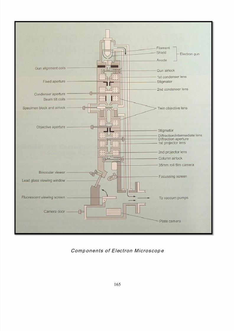
8/11/2019 30 Th October Micrscope Final
http://slidepdf.com/reader/full/30-th-october-micrscope-final 165/229
165
Components of Elect ron Microscop e

8/11/2019 30 Th October Micrscope Final
http://slidepdf.com/reader/full/30-th-october-micrscope-final 166/229
166
Anode:
The anode, an apertured disk, is positioned a short distance
away from the shield.
As the anode is kept at zero potential, electrons are attracted away
from the effective source and accelerate through the anode aperture
and into the column. The speed at which the electrons move
depends on the voltage difference between the effective source and
the anode: this voltage is thus referred to as the accelerating voltage.
Since the wavelength of the emergent electron beam is inversely
proportional to the accelerating voltage, the resolving power of the
microscope is directly affected by the operation of the electron gun.
This suggests that to gain maximum resolution it is necessary to
operate at the highest accelerating voltage possible. However, it is
also the case that as electron speed increases there is a
corresponding reduction in electron scatter as the beam passes
through the specimen, giving lower contrast in the final image. The
general view is therefore that the microscope should be operated at
the highest accelerating voltage that allows structures in the
specimen to be clearly discriminated. For most situations this will be
between 80-120 kV.
8/11/2019 30 Th October Micrscope Final
http://slidepdf.com/reader/full/30-th-october-micrscope-final 167/229
167
Classical vs. electron optics
1) Classical optics: The refractive index changes abruptly at a
surface and is constant between the surfaces. The refraction of light
at surfaces separating media of different refractive indices makes it
possible to construct imaging lenses. Glass surfaces can be shaped.
2) Electron optics: Here, changes in the refractive index are gradual
so rays are continuous curves rather than broken straight lines.
Refraction of electrons must be accomplished by fields in space
around charged electrodes or solenoids, and these fields can assume
only certain distributions consistent with field theory. There is a
serious disadvantage in that they cannot be shaped to correct for
chromatic aberration and other errors. In practice, electronic lenses
are difficult to manufacture and typically display spherical and
chromatic aberrations as well as astigmatism.
Spherical aberration is caused by electrons at the periphery of
the lens being focused closer to the lens than those in the central
region. This problem is minimized simply by using apertures to block
peripheral electrons from entering the lens in the first place.
Apertures made from molybdenum or platinum need to be cleaned
regularly, unlike those made from gold foil which is self-cleaning.

8/11/2019 30 Th October Micrscope Final
http://slidepdf.com/reader/full/30-th-october-micrscope-final 168/229
168
Chromatic aberration is due to electrons of different speed
(and thus wavelength) being focused at different planes. It is
primarily a function of the electrons losing speed as they pass
through the section itself and it gives rise to blurred images. The
effect is minimized by using thin sections and high accelerating
voltages combined with balanced lens currents.
Astigmatism is the result of asymmetry in the magnetic field
and reflects flaws in lens construction. It is also exacerbated by
contamination of the lens or other components in the electron
pathway. The problem is predominantly overcome by positioning
additional small electromagnets ('stigmators') around the primary
lens. The supplementary magnetic fields generated compensate for
the discrepancy in the primary field. Regular checking and
adjustment of the stigmators is necessary to maintain optimal image
quality.
Lens arrangement and image formation
The arrangement and function of lenses in the transmission
electron microscope is also analogous to that in the compound light
microscope. Electrons generated by the electron gun are collected
by a condenser lens system which is responsible for determining the

8/11/2019 30 Th October Micrscope Final
http://slidepdf.com/reader/full/30-th-october-micrscope-final 169/229
169
beam diameter (spot size) and maximizing specimen illumination.
The electrons that pass through the specimen (transmitted electrons)
then enter the imaging system which consists of the objective,
intermediate and projector lenses. The fundamental roles of these
lenses are to focus, magnify and direct the beam onto the viewing
screen or image recording unit (camera or digital imaging system).
The inherent difficulty associated with locating and re-locating
ultrastructural features, as well as the fragility of grids and sections
necessitates the use of some form of image recording mechanism.
Photographic film specifically manufactured for TEM remains the
most common system in use as it provides excellent levels of
resolution and image clarity. More recently developments in high-
resolution digital cameras have allowed images to be captured and
stored electronically. An additional advantage is that digital cameras
can operate at very low illumination levels thus minimizing beam-
induced specimen damage. By interfacing with the appropriate
software digital images with low contrast (that occur at higher
accelerating voltages) can be enhanced and various forms of
morphological and densitometric analyses can be performed.

8/11/2019 30 Th October Micrscope Final
http://slidepdf.com/reader/full/30-th-october-micrscope-final 170/229
170
Transmission electron microscopes produce two-dimensional
images. 1, 2, 3, 4
Transmission Electron Microscope
Tissue preparation for Transmission Electron Microscopy:
Although accelerated at great speed, the electron beam is only
capable of penetrating around 100nm. Thus in order to obtain a high
quality image & optimize the resolution of the instrument it is
necessary to section the tissue to a thickness of around 80nm.
Sectioning at this level requires tissues to be embedded in extremely
rigid material like synthetic resins. Resins are also capable of
withstanding the vacuum in the electron microscope column & the
heat generated as the electrons pass through the section. In most
circumstances, hydrophobic epoxy resins are preferred.

8/11/2019 30 Th October Micrscope Final
http://slidepdf.com/reader/full/30-th-october-micrscope-final 171/229
171
Flow chart illustrating the steps in the preparation of specimens for
diagnosis by electron microscopy .

8/11/2019 30 Th October Micrscope Final
http://slidepdf.com/reader/full/30-th-october-micrscope-final 172/229
172
Fixation - Primary fixation with Glutaraldehyde to stabilize the
proteins followed by osmium tetroxide which retains lipids.
Dehydration - replacing water with organic solvents such as
ethanol or acetone.
E mbedding - infiltration of the tissue with a resin such as
araldite or epoxy for sectioning.
Sectioning - produces thin slices of specimen, semitransparent
to electrons. These can be cut on an ultra microtome with a
diamond knife to produce very thin slices. Glass knives are also
used because they can be made in the laboratory and are
much cheaper.
Collection of sections- Ultra thin sections are mounted onto
specimen grids for viewing. Grids measure 3.05 mm in
diameter & are made of conductive material, commonly copper,
nickel or gold. A large range of patterns & mesh sizes are
available with 200 square mesh being commonly used.

8/11/2019 30 Th October Micrscope Final
http://slidepdf.com/reader/full/30-th-october-micrscope-final 173/229
173
Staining - uses heavy metals such as lead, uranium or tungsten
to block electrons to give contrast between different structures,
since many (especially biological) materials are nearly
"transparent" to electrons (weak phase objects). 1
Applications:
A major application is to define tumor classification, when light
microscopy is equivocal & when proper therapy & prognosis
depend on accurate diagnosis. In general, poorly differentiated
neoplasms may be better defined.
Some examples of specimen grids: (from top left)
mesh(200 size); slotted (200 size); Parallel with
divider (200 size); mesh(50 size); hexagonal (7size); parallel (75 size); freeze fracture; single hole;
slotted; tabbed mesh(400 size); tabbed
mesh(75size)
Apparatus for application of plastic support films. Thewater level is raised over the level of the wire mesh, on
which grids are then placed. Approximately 0.2ml ofliquid plastic film is dropped onto the water
surfaceover the submerged gids and the solventallowed to evaporate.The water is then drawn off,
allowing the film of plastic to settle onto the grids.
8/11/2019 30 Th October Micrscope Final
http://slidepdf.com/reader/full/30-th-october-micrscope-final 174/229
174
Ultrastructural diagnosis is useful especially in endocrine tumor.
Confirmation of small cell anaplastic carcinoma of neuroendocrine
type is enhanced.
Differential diagnosis of small cell tumors of possible Ewing‘s type
is supported, especially in pediatric age range (in which the
differential diagnosis includes neuroblastoma,
lymphoma/leukemia, embryonal rhabdomyosarcoma).
Other important applications include diagnosis of some spindle
cell tumors, distinction in occasional instances between carcinoma
& sarcoma & confirmation of amelanotic melanoma, in which it is
possible to identify premelanosomes.
Diagnosis of poorly differentiated leukemias, some lymphomas &
of histiocytosis-X is sometimes enhanced by electron microscopy.
EM is helpful in differential diagnosis between lymphoma &
undifferentiated carcinoma & sometimes in differential diagnosis
between primary & metastatic tumor.
Certain viral & infectious diseases, Metabolic/storage diseases.
Direct examination of specimens allows rapid identification of virus
particles & detection of viruses that are difficult or impossible to
cultivate (rotaviruses, hepatitis A virus). Fluid for examination is

8/11/2019 30 Th October Micrscope Final
http://slidepdf.com/reader/full/30-th-october-micrscope-final 175/229
175
dried onto a copper grid & examined. About one million virus
particles per ml are needed if they are to be detectable. The
sensitivity can be increased by reacting the fluid with antiviral
antibody so that clumps of virus particles are visible. This is
known as immunoelectron microscopy, a technique analogous to
immunofluorescence in light microscopy. 17
Electron micrograph of a Bacteriophage without shadowing (A) &
with shadowing (B)

8/11/2019 30 Th October Micrscope Final
http://slidepdf.com/reader/full/30-th-october-micrscope-final 176/229
176
Effects of wavelength on resolution: In each sketch the circles
represent wavelengths: in A-electrons, B-Visible light. In A the
projected image reveals all of the details of the form of the object. In
B image lacks detail.
Limitations:
Sampling errors
Expensive
Time consuming
Usually not useful in distinction between benign & malignancy.
Utility is diminished by crushing or drying.
Glutaraldehyde should be avoided since it contains a

8/11/2019 30 Th October Micrscope Final
http://slidepdf.com/reader/full/30-th-october-micrscope-final 177/229
177
precipitate.
The role of EM has recently been somewhat eroded by rapid
advances in immunocytochemistry for the differential diagnosis
of tumors.
SCANNING ELECTRON MICROSCOPE
Introduction to scanning electron microscopy:
The scanning electron microscope works by bouncing
electrons off of the surface and forming an image from the reflected
electrons. Actually, the electrons reaching the specimen (the 1 °
electrons) are normally not used (although they can form a
transmitted image, similar to standard TEM), but they incite a second
group of electrons (the 2 ° electrons) to be given off from the very
surface of the object. Thus, if a beam of primary electrons is scanned
across an object in a raster pattern (similar to a television scan), the
object will give off secondary electrons in the same scanned pattern.
These electrons are gathered by a positively charged detector, which
is scanned in synchrony with the emission beam scan. Thus, the

8/11/2019 30 Th October Micrscope Final
http://slidepdf.com/reader/full/30-th-october-micrscope-final 178/229
178
name scanning electron microscope with the image formed by the
collection of secondary electrons.
The SEM generally has a lower resolving power than the
TEM; however, it is particularly useful for providing three-dimensional
images of the surface of microscopic objects. Scanning electron
microscope resolutions are currently limited to around 25 Angstroms.
By correlating the sample scan position with the resulting signal, an
image can be formed that is strikingly similar to what would be seen
through an optical microscope. The illumination and shadowing show
a quite natural looking surface topography.
Electron beam generation
The electron gun in a scanning electron microscope is the
source for the electron beam used to probe the sample. Electrons are
emitted from a cathode, accelerated by passage through electrical
fields and focused to a first optical image of the source. The size and
shape of the apparent source, beam acceleration and current are the

8/11/2019 30 Th October Micrscope Final
http://slidepdf.com/reader/full/30-th-october-micrscope-final 179/229
179
primary determining factors in the performance and resolution of a
scanning electron microscope. 4, 5, 18
Samples viewed under an electron microscope may be treated in
many ways:
Cryofixation - freezing a specimen so rapidly, to liquid nitrogen
or even liquid helium temperatures, that the water forms
vitreous (non-crystalline) ice. This preserves the specimen in a
snapshot of its solution state. An entire field called cryo-electron
microscopy has branched from this technique. With the
development of cryo-electron microscopy (CEMOVIS), it is now
possible to observe virtually any biological specimen close to its
native state.
Fixation - preserving the sample to make it more realistic.
Glutaraldehyde - for hardening - and osmium tetroxide - which
stains lipids black - are used.
Dehydration - replacing water with organic solvents such as
ethanol or acetone.
Embedding - infiltration of the tissue with a resin such as
araldite or epoxy for sectioning.

8/11/2019 30 Th October Micrscope Final
http://slidepdf.com/reader/full/30-th-october-micrscope-final 180/229

8/11/2019 30 Th October Micrscope Final
http://slidepdf.com/reader/full/30-th-october-micrscope-final 181/229
181
extremely fragile "pre-shadowed" metal replica of the fracture
surface is released from the underlying biological material by
careful chemical digestion with acids, hypochlorite solution or
SDS detergent. The still-floating replica is thoroughly washed
from residual chemicals, carefully fished up on EM grids, dried
then viewed in the TEM.
Ion Beam Milling - thins samples until they are transparent to
electrons by firing ions (typically argon) at the surface from an
angle and sputtering material from the surface. A subclass of
this is Focused ion beam milling, where gallium ions are used
to produce an electron transparent membrane in a specific
region of the sample, for example through a device within a
microprocessor.
An important technique in Scanning electron microscopy is the
use of "shadowing." This involves depositing a thin layer of
heavy metal (such as platinum) on the specimen by placing it in
the path of a beam of metal ions in a vacuum. The beam is
directed at a low angle to the specimen, so that it acquires a
"shadow" in the form of an uncoated area on the other side.
When an electron beam is then passed through the coated

8/11/2019 30 Th October Micrscope Final
http://slidepdf.com/reader/full/30-th-october-micrscope-final 182/229
182
preparation in the electron microscope and a positive print is
made from the "negative" image, a three dimensional effect is
achieved
Evaporation, Thin-film deposition, or sputtering of carbon, gold,
gold/palladium, platinum or other conductive material to avoid
charging of non conductive specimens in a scanning electron
microscope. 5, 7, 18
Modifications of SEM:
It is possible to focus the primary electrons in exactly the same
manner as a TEM. Since the primary electrons can be focused
independently of the secondary electrons, two images can be
produced simultaneously. Thus, an image of a sectioned material can
be superimposed on an image of its surface. The instrument then
becomes a STEM, or Scanning-Transmission Electron Microscope. It
has the same capabilities of a TEM, with the added benefits of an
SEM.

8/11/2019 30 Th October Micrscope Final
http://slidepdf.com/reader/full/30-th-october-micrscope-final 183/229
183
SEM allows a good deal of analytical data to be collected in
addition to the formed image. As the primary electrons bombard the
surface of an object, they interact with the atoms of the surface to
yield even more particles and radiations other than secondary
electrons. Among these radiations are Auger electrons, and
characteristic X-rays. The X-rays have unique, discreet energy
values, characteristic of the atomic structure of the atom from which
they emanated. If one collects these X-rays and analyzes their
inherent energy, the process becomes Energy Dispersive X-ray
Analysis. Combining the scan information from secondary and Auger
electrons, together with the qualitative and quantitative X-ray
information allows the complete molecular mapping of an object's
surface.
Finally, the scanning microscope has one further advantage
that is useful in cell structure analysis. As the electron beam scans
the surface of an object, it can be designed to etch the surface. That
is, it can be made to blow apart the outermost atomic layer. As with
the emission of characteristic x-rays, the particles can be collected
and analyzed with each pass of the electron beam. Thus, the outer
layer can be analyzed on the first scan, and subsequently lower

8/11/2019 30 Th October Micrscope Final
http://slidepdf.com/reader/full/30-th-october-micrscope-final 184/229
184
layers analyzed with each additional scan. Electrons are relatively
small, and the etching can be enhanced by bombarding the surface
with ions rather than electrons (the equivalent of bombarding with
bowling balls rather than BB's). The resultant Secondary Emissions-
Ion Scanning data can finally be analyzed and the three- dimensional
bit-mapped atomic image of an object reconstructed.
Scanning electron microscopes are often coupled with x-ray
analyzers. The energetic electron beam - sample interactions
generate x-rays that are characteristic of the elements present in the
sample. Many other imaging modes are available that provide
specialized information.
Because the signal is incoherent (unlike the conventional TEM
bright-field image), the resolution of the ADF image is higher than that
obtainable in the TEM by a factor of almost two. Another important
advantage of STEM is that any analytical signal, such as X-ray
fluorescence spectroscopy and electron energy loss spectroscopy
(EELS), can also be obtained at high resolution (0.1 nm in the very
best, aberration-corrected STEMs). Other signals include Auger

8/11/2019 30 Th October Micrscope Final
http://slidepdf.com/reader/full/30-th-october-micrscope-final 185/229
185
spectroscopy, electron nanodiffraction and high-resolution secondary
electron imaging. 2, 4, 15, 18, 20
Disadvantages:
1. Real electron microscope images do not carry any color
information, they are greyscale.
2. Electron microscopes are expensive to buy and maintain. As they
are sensitive to vibration and external magnetic fields, suitable
facilities are required to house microscopes aimed at achieving high
resolutions.
3. The samples have to be viewed in vacuum, as the molecules that
make up air would scatter the electrons.
4. The samples have to be prepared in many ways to give proper
detail, which may result in artifacts purely as the result of treatment.
8/11/2019 30 Th October Micrscope Final
http://slidepdf.com/reader/full/30-th-october-micrscope-final 186/229
186
Chapter- XVI
Stereomicroscope
It uses two separate optical paths with two objectives and two
eyepieces to provide slightly different viewing angles to the left and
right eyes. In this way it produces a three-dimensional (3-D)
visualization of the sample being examined.
Great working distance and depth of field here are important
qualities for this type of microscope. Both qualities are inversely
correlated with resolution: the higher the resolution (i.e.,
magnification), the smaller the depth of field and working distance. A
stereo microscope has a useful magnification up to 100×. The
resolution is maximally in the order of an average 10× objective in a
compound microscope, and often much lower.
A Colour CCD camera of moderate quality documents all
observations. Particularly in molecular biology and in gene
technology this new observation technique offers ideal conditions for
in-vivo and in-situ investigations of living organisms in real time.
Applications:
8/11/2019 30 Th October Micrscope Final
http://slidepdf.com/reader/full/30-th-october-micrscope-final 187/229
187
The stereo microscope is often used to study the surfaces of
solid specimens or to carry out close work such as sorting, dissection,
microsurgery, and the like.
A stereomicroscope is a highly mobile and readily
maneuverable microscope, which can be used to examine any object
that is unable to be placed on the stage of a conventional
microscope. Equipped with a rollable floor stand, highly flexible
extension arms and fibre-optic light guide, the microscope can be
employed to examine objects virtually at any axes and angles, with
an impressive 3D effect, profound depth of field and richness of
contrast.
Ultraviolet & television color-translating microscopes:
One value of ultraviolet light is that it is passed by some parts of
a cell but is more/less completely absorbed by other parts, thus
creating contrasts between otherwise indistinguishable intracellular
structures. Unfortunately, direct vision by ultraviolet light is not
feasible & the object can therefore be studied only by means of
photographs.
8/11/2019 30 Th October Micrscope Final
http://slidepdf.com/reader/full/30-th-october-micrscope-final 188/229
188
The ultraviolet television microscope permits continuous
observation of the object under ultraviolet illumination without the
intermediation (with consequent distortion, blurring & delay) of
photographs. 4
IMAGE ANALYSIS
The practice of histology and histopathology has traditionally relied
upon the subjective interpretation of microscopic preparations by a
highly trained individual. The accuracy with which such interpretations
can be made is the foundation of histology and of histopathology. It is
important to note that these interpretations are based on pattern
recognition, that is, overall arrangements of elements within the
specimen, a task for which the human visual system is well suited.
The human visual system is not well suited for quantitative functions,
such as assessment of linear measurements, areas, or density of
stain. The human eye is a remarkable sensor, but one that is highly
adaptable. It is able to alter its sensitivity depending on the brightness
of the object being viewed. The eye is also a non-linear sensor, with a
response to brightness that more closely approaches a logarithmic
response. These two characteristics preclude accurate assessment
8/11/2019 30 Th October Micrscope Final
http://slidepdf.com/reader/full/30-th-october-micrscope-final 189/229
189
of density of specimens viewed through a microscope.
Human observers do not accurately estimate physical distances,
and areas of specimens. The eye is reasonably good at comparisons,
and most microscopists will 'estimate' sizes based on some internal
specimen object, such as the diameter of red blood cells. Even with
such comparisons, length and size estimates made by microscopists
are neither accurate nor highly repeatable. It is the purpose of all
types of image quantitation to eliminate observer-to-observer
variation, and produce evaluations that are accurate and repeatable.
Morphometry is the general term used to describe the
measurement of size parameters of a specimen. Size is here defined
as length, height and area of an object of interest. These basic
measurements can be combined to provide additional
measurements, such as perimeter, smoothness, centers, etc.
TRADITIONAL APPROACHES
The history of development of the microscope is filled with
clever devices designed to assist in performing Morphometry of
specimens. One such device is the camera lucida, which is an optical

8/11/2019 30 Th October Micrscope Final
http://slidepdf.com/reader/full/30-th-october-micrscope-final 190/229
190
system that projects an image of the specimen onto a surface
adjacent to the microscope. This projected image can be used to
draw the specimen, or to measure portions of the image. Accurate
measurements within these projected images require calibration of
the projection, in a manner identical to that used to calibrate reticules.
Photographic approaches have eliminated the use of the
camera lucida in many laboratories, as convenient cameras have
become universally available for microscopes. As with projections, a
photographic system must be calibrated, using a stage micrometer. In
addition to the calibration of the photographic negative, the enlarging
process must also be calibrated for accurate measurements. For both
camera lucida drawings and photographs, areas are generally
determined using a device called a Planimeter. A planimeter is a
mechanical device that is used to manually trace the outline of
objects of interest. Using a set of 'x' and 'y' calibrated wheels, the
total area of the object is determined.
Stereology is a technique developed for analysis of metals and
minerals, where generally the properties being measured relate to
number, size and distribution of some particle in the sample. Being
based in geometry and probability theory, and using statistical math-

8/11/2019 30 Th October Micrscope Final
http://slidepdf.com/reader/full/30-th-october-micrscope-final 191/229
191
ematics, stereology makes specific assumptions about the object
being analyzed. Since the foundation of stereology is statistical the
general nature of the distribution of whatever is being measured
should be describable using some statistic. This condition may be
met under specific conditions, such as examining the distribution of
chromatin 'clumps' within a cell nucleus, where the only object being
examined is a single nucleus. For highly ordered structures, such as
gland elements within an organ, the very organization of the structure
implies that there is no statistical distribution. Stereo logy can make
estimates of some parameters of specimens such as area of a total
image occupied by some particular component. Note that this is an
estimate. Use of stereology to derive measures of the three-
dimensional structure of cell and tissue specimens may provide
misleading information, since the probabilities used in the
mathematics assume that the entire volume of the specimen is
accurately reflected in the portion measured. While one cannot
disagree that stereology has provided many useful insights into
microscopic specimens, modern techniques of measurement can
provide real measures of the specimen, without any assumptions of
the distribution pattern. The development of newer forms of

8/11/2019 30 Th October Micrscope Final
http://slidepdf.com/reader/full/30-th-october-micrscope-final 192/229
192
microscopy (confocal) has extended this direct measurement
capability to the third dimension. With the speed of modern image
analysis systems, there is little justification for performing an estimate
of a cell or tissue parameter when the actual parameter can be
accurately measured, often in less time than is required for the
stereological approach.
Electronic light microscopy
Electronic measurements of light transmitted through
microscopic specimens have a long history, and roughly parallels the
development of photometers, spectrophotometers, and light detecting
devices. Until recently (1980s), these devices simply detected light,
and did not produce images. To use these early devices to produce
images, the portion of the specimen visible to the light detector had to
be restricted, and the specimen or image moved across this restricted
area to generate an actual image. Many mechanisms were
developed to acquire images using such techniques (Weid 1966,
Weid and Bahr 1970). These mechanisms tended to be expensive,
since they required high precision, and were also slow as the image
had to be acquired a small area at a time, and then 'put together' or
reconstructed into a recognizable image. The majority of literature

8/11/2019 30 Th October Micrscope Final
http://slidepdf.com/reader/full/30-th-october-micrscope-final 193/229

8/11/2019 30 Th October Micrscope Final
http://slidepdf.com/reader/full/30-th-october-micrscope-final 194/229

8/11/2019 30 Th October Micrscope Final
http://slidepdf.com/reader/full/30-th-october-micrscope-final 195/229
195
During the decade of the 1980s a variety of solid state sensors
were developed for television purposes. One technology in particular,
the CCD (Charge Coupled Device) camera matured into a
significantly useful device for microscopic imaging work. CCD
cameras continue to evolve and are the technology of choice for most
photometric and imaging microscopic studies. Recently a new
technology has emerged in solid-state cameras: CMOS or
Complementary Metal Oxide Semiconductor cameras. These devices
promise rapid image acquisition, low cost and the potential for some
image manipulation within the camera detector itself.
Solid-state cameras, whether CCD or CMOS are available in
either monochrome or color versions. Color cameras may use two
different techniques to generate a color image.
1. In one approach there are three separate detector arrays, each
with a color filter in front of the array. A prism or mirror system is used
to split the image coming from the microscope into three separate but
identical images so each detector sees the same image. The color
filters are red, green and blue, since a red image, a green image and
a blue image can be combined to create a full color image. This type
of camera is called a three chip color - camera.

8/11/2019 30 Th October Micrscope Final
http://slidepdf.com/reader/full/30-th-october-micrscope-final 196/229
196
2. The second approach to color cameras uses a single detector chip,
and places a pattern of color dots over the individual pixels. Again,
these color dots are red, blue and green. The most common pattern
for these dots is the Bayer pattern. In the Bayer pattern, there are
actually four dots per 'repeat,' since for each red and each blue dot
there are two green dots. This type of camera is called a single chip
color camera.
Because the three-chip camera has three individual detectors,
and also a beam-splitting system to divide the image, these cameras
are more expensive than a single-chip camera. Essentially, a three-
chip camera is three separate cameras in one. The advantage of the
three-chip camera is that every pixel is 'real,' that is, it is generating a
true signal. The disadvantage is that there may be differences in
sensitivity of a 'red' pixel and a 'green' pixel that are seeing the exact
same spot of an image. Use of a three-chip camera for photometry
where various colors are examined requires careful calibration and
correction of any variation in output between the separate detector
chips.
The single-chip camera can produce excellent color images,

8/11/2019 30 Th October Micrscope Final
http://slidepdf.com/reader/full/30-th-october-micrscope-final 197/229
197
but must be used carefully for quantitative work, and is unsuitable for
photometry, because only one pixel out of four (two in the case of
green) is actually seeing the specimen at the point of maximum
absorption. The other pixels in the Bayer pattern are being
approximated, by assigning their 'red' value to the same value as the
one real 'red' pixel in the pattern. In addition to the approximation of
true signal for a given color, the Bayer pattern results in a real loss of
Bayer pattern
resolution at the sensor level. Since only one of every four pixels (for
red and blue) actually sees a red or blue portion of the specimen, the
true resolution of the single-chip camera is one-fourth the total
numbers of pixels in the array.
The three-chip color camera is essentially three monochrome
cameras, with each camera having a different colored filter in front of
the camera detector. Software is then used to combine the three
separate images into a full-color image. This suggests that it is
possible to use a monochrome camera to capture full color images. A

8/11/2019 30 Th October Micrscope Final
http://slidepdf.com/reader/full/30-th-october-micrscope-final 198/229
198
number of cameras provide a mechanism for doing this. Within the
camera itself, there is either an electronic filter, or a filter wheel
carrying glass filters. To capture an image, three sequential images
are taken, each through a different colored filter. These images are
then combined to produce the full-color image. It is possible to do this
same thing, using a simple monochrome camera. One would place a
red filter in the light path of the microscope, and capture a 'red'
image. The same thing would then be done for 'blue' and for 'green.'
The result would be three separate images of the same specimen, in
different colors, and when these three-color planes are combined
using software, the result is a full-color image.
Cameras used for imaging are also described in terms of signal
resolution per individual pixel. This signal resolution is commonly
described as bit depth or gray levels (for monochrome cameras). The
signal resolution is a specification that describes the number of
divisions of the signal between 0 (no signal) and maximum signal. A
common value is 256 levels, and these divisions are often also
described as gray levels. They are based on the digital progression
by powers of two, and therefore a 256-level signal corresponds to 8
bits of resolution (2 to the eighth power). Many modern cameras

8/11/2019 30 Th October Micrscope Final
http://slidepdf.com/reader/full/30-th-october-micrscope-final 199/229
199
provide 10 or 12 bits signal resolutions. With a 12-bit camera, 4096
gray levels can be obtained. As the signal resolution increases, the
susceptibility of the signal to perturbation increases.
It is important to note the differences between cameras used to
capture images through the microscope, and the same image, viewed
with the human eye. The human eye is a remarkable detector of light
and of color. However, it is a non-linear, highly adaptive sensor. In
addition, the resolution of the eye detector (retina) varies across the
surface of the retina. Under ideal conditions, most individuals with
excellent eyesight can distinguish between 30 and 35 brightness
levels (gray levels). This is a far cry from the 256 or higher number of
levels seen by a digital camera. Therefore, a solid-state camera can
always detect intensity variations that would be invisible to the human
observer. This translates to the ability to detect finer detail within an
image than can be resolved by a human observer.
The human eye adapts to light intensity, so the 30 or 35 gray
levels that are detected vary depending on the intensity of the light,
and the immediately preceding light exposure of the eye. This is one
of the reasons why individuals must 'dark adapt' prior to doing fluo-
rescence microscopy. The same phenomenon occurs in bright field
8/11/2019 30 Th October Micrscope Final
http://slidepdf.com/reader/full/30-th-october-micrscope-final 200/229
200
microscopy, but is seldom recognized. If an individual is asked to
assess the density or 'darkness' of a stain, the assessment will vary
depending on whether the individual has been in a dim environment
or a bright environment just prior to performing the assessment.
Color capture is another area in which a camera differs from the
human eye. While there is much that is still unknown as to the way in
which the eye-brain combination processes color, the camera
provides a fixed model. The construction of the camera itself is based
on the RGB (red, blue, green) model of color. There are many other
models of color, and those that incorporate intensity and saturation
information appear more intuitive to human users of image systems.
One common model that employs such a system is the HSI (hue,
saturation, intensity) model. Software programs are available that
permit images to be converted from one type of color space model to
another, and often such conversions are useful when one works with
full color images.
Photographic color film is balanced for the type of light used to
illuminate the scene. The type of light is specified by a 'color
temperature' number. . Specialty films intended for microphotography
may be balanced for 'tungsten' illumination, with a color temperature

8/11/2019 30 Th October Micrscope Final
http://slidepdf.com/reader/full/30-th-october-micrscope-final 201/229
201
of 3,200° Kelvin. The 'color temperature' of a light source is actually a
measure of the intensity of the various components of the light
source, in the red, green and blue regions of the spectrum.
Photographic film records all of these components simultaneously,
and there is little opportunity to 'correct' values, other than limited
adjustment during processing. With a solid-state camera and capture
software, the situation is different. Each of the image components
(red, blue and green) are available as individual images. They are
combined to produce the final image. Since the individual
components (color planes) are available, it is possible to 'color
correct' the image. This is generally done in the capture software, or
the camera itself.
Computers:
Computers suitable for image analysis range from RISC based
workstations to personal computers. A variety of sophisticated image
analytic tools (programs) are available for each of these platforms. In
addition to commercial offerings, there are a number of freeware or
shareware programs available for the personal computers. All of
these offerings include the variety of image analysis processes,
8/11/2019 30 Th October Micrscope Final
http://slidepdf.com/reader/full/30-th-october-micrscope-final 202/229
202
although there is little standardization of terminology for specific types
of processes. In general these software systems are organized as a
way to display an image. The image may either be captured from a
camera, or retrieved from storage. Once the image is available, the
user can select, through menus or tool bars, a variety of image
manipulation tools. When the tool is applied to the image, the results
can be seen immediately. Most systems also provide a mechanism to
back up or undo, in case the result was not satisfactory. Among the
best known of these is the program originally designed for the Apple
computers, named NIH Image. A recent addition to the list of
available image analytic programs is Image-I. This program is also
freely available, and because it is written in the JAVA language, can
run on any computer which supports JAVA.
All image analysis programs must provide mechanisms to
display images, read images from a source (camera or storage), and
ultimately save the image and any derived data to storage. In modern
computers, these functions are part of a GUI (graphical user inter-
face) that permits the user to actually see the image and the various
alterations to it during and after various image analytic or
manipulation steps.

8/11/2019 30 Th October Micrscope Final
http://slidepdf.com/reader/full/30-th-october-micrscope-final 203/229
203
As camera resolutions increase, they often exceed the display
capability of many computer displays. As an example, consider a
common camera resolution available today, 1024 x 1310. The actual
image from such a camera is larger than the common display res-
olution of many computers, which may be 800 x 600. Another
common display resolution is 1024 x 756. In both cases, the larger
image is displayed completely on the monitor. This is accomplished
within the display program, by simply reducing the image to fit within
the monitor resolution. Therefore the displayed image may not
accurately represent the 'real' image that has been captured and is
available for analysis. Some capture/display programs provide tools
to permit the user to display the image at actual resolution, even
though only a portion of the image is seen on the screen. Such
programs allow the user to scroll over the image in order to see the
entire image. Many output devices, such as printers, actually reduce
the size of the image, and therefore lose resolution as compared to
the original image.
It is important to realize that an image, to the computer, is
simply an array of values of the individual pixels. For 8-bit
monochrome images, this would be a sequence of numbers, with

8/11/2019 30 Th October Micrscope Final
http://slidepdf.com/reader/full/30-th-october-micrscope-final 204/229
204
values for each ranging between 0 and 255. Image file storage
formats specify the number of pixels per row, and the total number of
rows. This information is part of the 'header' information in the file
storage, and is required for proper display and analysis of the
images. The user ordinarily does not have to worry about this
information, since it is taken care of transparently by the image
software. Because the computer software considers the image to be
an array of X by Y dimension, any pixel in the image can be
individually addressed if its location is known within the array. In the
case of color images, the actual image is stored as a sequence of
colored pixels, i.e., red, blue and green. To extract the 'green' image,
one would read every third pixel from the file. There are a variety of
formats for image file storage, and the programmer should be sure to
verify the 'bit order' in use prior to attempting to extract specific
information.

8/11/2019 30 Th October Micrscope Final
http://slidepdf.com/reader/full/30-th-october-micrscope-final 205/229
205
Image analysis by computers
IMAGE ANALYSIS PROCESSES
Point processes
Most forms of image analysis of microscope images start
with a category of operations classically defined as point processes.
These processes are relatively simple, yet are basic to most image
operations. A point process acts on an individual pixel within the
image, and may modify the value of that pixel depending on the previ-

8/11/2019 30 Th October Micrscope Final
http://slidepdf.com/reader/full/30-th-october-micrscope-final 206/229
206
ous value. A common use of a point process is to change the value of
each pixel to some other value, depending on the original value. Such
an operation may make use of a LUT (look-up table). A common use
for such an operation is in a pseudo-color operation, where a gray
scale image is divided into a number of 'levels,' i.e., all pixel values
between 0 and 20 might be colored 'red,' all values between 21 and
50 might be colored 'blue,' etc. Since the human eye recognizes color
variations much more easily than density variations, such a point
operation might well make interpretation of a gray scale image easier.
Point processes are used to change the overall intensity of an
image. Suppose an image is captured, and the background appears
too dark, by adding a constant to every pixel the result is an image
that looks brighter. Often, in the process of color balancing the
individual color planes of a color image, it is a point process that is
used to set the 'clear' or 'background' pixels to 'white'. Point
processes can also be used to convert an image to a negative of the
original image. This is quite useful if the image is analyzed with a
system different from the one used for capture. It is also a useful
function for many intermediate image manipulations, particularly

8/11/2019 30 Th October Micrscope Final
http://slidepdf.com/reader/full/30-th-october-micrscope-final 207/229
207
where images may be combined with one another.
Image contrast stretching is another example of a point
process. In a contrast stretch (image equalization), the range of gray
levels in the image is expanded. In many specimens, the actual
image values cover a relatively narrow range of the total available
gray values. As an example, in a nuclear preparation stained for DNA
with the Feulgen procedure, the total gray levels represented by the
stained nuclei occupy only about 30 per cent of the total available
levels. By contrast, stretching these gray levels to cover the entire
range of available values (256 levels), additional details can often be
seen and/or measured in such contrast stretched images.
By far the most common point process in image analysis
is image thresholding. Image thresholding is used to segment an
image into areas that have some particular interest, such as a
particular staining pattern. The action of a threshold is simple. The
user selects a particular gray level. The point process then sets all
pixels with a value lower than this threshold value to '0,' and all
values above this threshold value to '1.' In other words, the image is
converted to a binary image. While this simple threshold is sufficient

8/11/2019 30 Th October Micrscope Final
http://slidepdf.com/reader/full/30-th-october-micrscope-final 208/229
208
for some purposes, such as determining the total area in the image
that is above some level (generally, the area of the image that is
'stained' by whatever is being analyzed), the simple binary image is
more generally used to combine with the original image to produce
some type of 'mask.' A common implementation is to combine the
binary image with the original image in such a way that all '0' or
background pixels are left '0,' while all '1' pixels are left with their
original image value. Such an operation leaves the desired portions
of the image visible, with the remainder eliminated from the image. A
second threshold step is often performed, thresholding from the
opposite direction. After this step, a group of objects of 'medium' gray
level could be separated or segmented from both lighter and darker
objects. Another common implementation is to combine the two
threshold operations with a pseudo-color or LUT (look up table)
operation, and simply place a transparent colored mask over the
desired objects, leaving the entire original image visible.
Area processes:
Area processes use groups of pixels either to derive information
from the image or to alter the image in some specific manner. In

8/11/2019 30 Th October Micrscope Final
http://slidepdf.com/reader/full/30-th-october-micrscope-final 209/229
209
general, area processes involve a small portion of the image, in a
two-dimensional matrix. The matrix is generally made up of an odd
number of 'row' pixels and an odd number of 'column' pixels (a
convolution kernel). It is the pixel in the center of this matrix that may
be altered after performing the area process. Many of the area
processes are often referred to as convolutions. Convolutions com-
monly are based on matrix sizes of 3, 5, 7 or sometimes larger
dimensions. In the area process, a convolution matrix is defined. The
convolution matrix is placed over the image, and each pixel over
which the convolution mask lies is multiplied by the number contained
within the convolution mask. All of these multiplied pixel values are
then summed, and the sum is used to replace the central pixel. The
mask is then moved one pixel further along, and the process
repeated. In practice, the 'changed' pixel is used to construct a new
image, since the process of convolution would fail if the image being
analyzed were being altered during analysis. In other words, the
convolution does not change the 'original' image, but creates a new,
modified image based on the original.
Area processes in general are often called spatial filtering
operations, since they yield information about the rate of change of

8/11/2019 30 Th October Micrscope Final
http://slidepdf.com/reader/full/30-th-october-micrscope-final 210/229
210
intensities within the image. In fact, it is these rates of change that are
exploited by many common convolution filters. Typical area
processes are those used for spatial filtering such as high pass and
low pass filters. A low pass filtered image will reduce the contrast of
an image. Such an operation is often useful to remove unwanted
noise spike within an image. A high pass filtered image increases
contrast within the image, and is often used to improve the ability to
detect edges or other structures within the image.
An important type of spatial filtering is edge detection. A variety
of convolution matrices are available to perform it. Often, some type
of edge detection is used to perform segmentation within an image,
particularly if the area to be segmented is close in gray value to other
structures within the image, and thresholding is difficult.
While area processes are extremely important in image
analysis, they are computationally intensive processes. As an
example, a point process need only look at each pixel in an image
one time. An area process, in the simplest case, must look at each
pixel times the size of the convolution matrix. For a convolution matrix

8/11/2019 30 Th October Micrscope Final
http://slidepdf.com/reader/full/30-th-october-micrscope-final 211/229
211
of 3 x 3, and an image of 1 million pixels, 9 million operations would
have to be performed. For matrices of 7 x 7, 49 million operations
would be required. High resolution, full-color images require a
considerable space for storage in the computers. There are various
methods of making images smaller (image compression), most of
these forms of compression are 'lossy,' that is, they discard image
information, and this information cannot be retrieved from the stored
image. Certain image storage formats allow a type of compression
that is based on sequences of image data where all the pixels are the
same (like large areas of background). This form of compression is
called run length encoding, and does not discard any image
information. However, for a typical image of a microscope specimen,
where there are few or no 'constant value' areas, run length encoding
may actually result in a larger image storage size than the original
image. As a practical matter, any image intended for future analysis
should not be stored in a compressed format, particularly in view of
the low cost of large capacity storage devices.
Frame processes:
Both point processes and area processes treat the image as a

8/11/2019 30 Th October Micrscope Final
http://slidepdf.com/reader/full/30-th-october-micrscope-final 212/229
212
series of pixels, and address each pixel in a specific manner. Frame
processes in contrast operate on the entire image. Often frame
processes use simple operations to add, subtract, multiply, divide, or
otherwise combine two images to produce a new third 'result' image.
A common use of a frame operation is to correct a microscope image
for uneven illumination. By collecting and 'temporarily' saving an
image of the 'background' (when no specimen is present), the
background image can then be subtracted from the specimen image.
This will effectively remove any debris or other image-degrading
elements that are inherent in the microscope and illuminator. A
common biological application for a frame process would be to detect
movement in a cell culture being observed at intervals. By tracking
these changes over time, a 'trail' can be mapped and applied over the
image to follow the movement of cells over time.
Geometric processes:
Geometric processes are quite different from the processes
discussed previously, since they are mainly used to reconstruct or
correct images. Geometric processes actually move pixels within the
image, and can therefore be used to correct defects such as geo-

8/11/2019 30 Th October Micrscope Final
http://slidepdf.com/reader/full/30-th-october-micrscope-final 213/229
213
metric distortion. Geometric processes are used to rotate images,
change scale, translate images and produce mirror images. It is
geometric processes that are used to interpolate images from 'real'
size to a size that can be displayed on the monitor in use. Geometric
distortion would include such image defects as a microscopic section
that was attached to the slide in a manner that distorted normal
morphology. In such a case, a geometric process could 'transform'
the image to straighten or otherwise return it to the shape believed to
be correct. Geometric processes are used to make the specimen
'look better,' and to prepare the image for display or output to a print
device.
These processes can be used to align 'stacks' of images, to
reconstruct three-dimensional models of specimens. Geometric
processes can also be used to create mosaic images. A mosaic
image is an image that is created from several smaller images. Using
a motor driven stage (scanning stage), an image system can travel
over a slide, each time moving the exact width of the previous image,
and collecting another image. Each collected image can then be
'added' to the previous one to create a large, mosaic image. With

8/11/2019 30 Th October Micrscope Final
http://slidepdf.com/reader/full/30-th-october-micrscope-final 214/229
214
appropriate software, the area where these small images join can be
a perfect, seamless match.
SPECIMEN PREPARATION FOR IMAGE ANALYSIS
The most common staining protocol for routine pathology is the
hematoxylin and eosin (H&E) stain. Interpretation of this stain is
straightforward for those trained in microscopic diagnosis. However,
this stain is quite difficult to use in image analysis. If we consider the
use of a monochrome camera, where all color is converted to shades
of gray, the problem becomes apparent. H&E stained specimens
when viewed as gray scale objects (like a black and white
photograph), lack the sharpness and clarity that a human observer
would detect when viewing the object in full color through the
microscope. Light microscope images depend on absorption of light
by the dyes used to stain the specimen. While the eye can readily
detect the differences between the blue to purple of hematoxylin from
the red of eosin, in a gray scale image there is little distinction
between these two colors. The basis for this lack of differentiation is
that the absorption curves of hematoxylin and eosin overlap over a

8/11/2019 30 Th October Micrscope Final
http://slidepdf.com/reader/full/30-th-october-micrscope-final 215/229
215
considerable portion of the visible spectrum (Fig. 33.4). This overlap
of absorption results in slowly varying shades of gray, rather than
abrupt transitions between the blue-purple of hematoxylin and the red
of eosin. This problem is not new to image analysis; it has plagued
photomicrography for many years. In the case of black and white
photography, one can improve the appearance of H&E stained
specimens by simply substituting some other acid dye for eosin that
does not have as great an absorption curve overlap with hematoxylin.
Dyes that work well for this are Orange G or Napthol Yellow S.
Since the digital cameras used for image analysis respond
differently than the eye, specimens intended for image analysis
require modifications of traditional staining methods. In the case of
specimens intended for analysis with monochrome (black and white)
cameras, the staining protocol must be optimized to permit the
camera to detect different portions of the specimen. Since essentially
all image analysis tasks begin with methods to segregate some
portions of the image from other portions, the staining methods
should not use dye combinations that produce any absorption over-
laps. It is also desirable that the density of the various stained
components should be significantly different so the resulting 'gray

8/11/2019 30 Th October Micrscope Final
http://slidepdf.com/reader/full/30-th-october-micrscope-final 216/229

8/11/2019 30 Th October Micrscope Final
http://slidepdf.com/reader/full/30-th-october-micrscope-final 217/229
217
greatly improve the ability to detect the stained components. For
objects that are stained red to magenta, a green filter will be found
quite useful. Often when the specimen is stained with a method that
utilizes a combination of dyes, a filter can be found that will enhance
the ability to segment the monochrome image to select the
component of interest.
As has been mentioned in the discussion of photometry through the
microscope, accurate measurement of the concentration of a material
in a stained specimen requires:
A. A stoichiometric relationship between the dye and the component
of interest
B. An absorbing dye
C. An intact object, rather than a sectioned object (unless the
measurement simply
determines concentration per unit volume).
DAB (diaminobenzidine) is not a stain that should be employed
when concentrations of a cell or tissue component are desired. Other
chromogens for peroxidase in immunostains are true absorbing dyes,
and are a more appropriate choice.
Every step of the process must be rigidly controlled, beginning

8/11/2019 30 Th October Micrscope Final
http://slidepdf.com/reader/full/30-th-october-micrscope-final 218/229
218
with specimen collection and fixation. The length of time in fixative
must be precisely defined also, since length of exposure to most
fixatives may alter the binding of the final stain to the specimen. If the
specimen displays any 'edge effect,' that is, increased or decreased
staining at the periphery of the specimen as compared to the center,
measurements must always be taken at a specified distance from the
periphery. While on the subject of fixation, it should be mentioned that
common fixatives may give very different results with particular
staining protocols. For a quantitative study, it is imperative that all
specimens included in the study be fixed in the same fixative.
Staining protocols that are routine for visual examination may
prove problematic for quantitative work. As the length of time a
specimen is exposed to a particular staining step decreases, the
percentage of error that can be introduced by the physical time
required to insert or remove the slides from the staining solution may
become a significant source of error. In other words, if the total time
in a particular staining step is only 1 minute, a variation of 10 seconds
amounts to almost a 20 percent variation in staining time. To reduce
the potential error introduced by short staining times, staining
methods should be modified by decreasing stain concentrations, and

8/11/2019 30 Th October Micrscope Final
http://slidepdf.com/reader/full/30-th-october-micrscope-final 219/229
219
then increasing staining times. As a general guide, any staining time
that is shorter than 10 minutes should be extended to between 30
minutes and an hour, by reducing stain concentration. This strategy
effectively controls errors introduced by the time required to
physically introduce or remove specimens from staining solutions. For
stains that require differentiation, often this is done with a series of
dips, with differentiation controlled by an experienced technician. This
type of differentiation should be optimized by changing the
concentration of the differentiation solution in order to extend the dif-
ferentiation steps to a defined time, preferably long enough to
eliminate the effect of short times. In addition to times in actual
staining solutions, stain results may also be influenced by various
dehydration sequences. Standardization of every step of a stain
protocol including deparaffinization, hydration, staining,
differentiation, dehydration, clearing, and cover slipping will greatly
improve variability of specimens analyzed with image analysis
systems.
For studies that purport to measure the total amount of a
material present, the intact object containing that material must be
present in the slide. For many cellular materials, this means that
8/11/2019 30 Th October Micrscope Final
http://slidepdf.com/reader/full/30-th-october-micrscope-final 220/229
220
whole cells, such as from tissue cultures, be used. Another strategy is
simply to disaggregate tissues, and select intact cells for analysis.
Sectioned material may be employed for many image analysis tasks,
but generally is not suitable for measuring the total amount of
material present in a given cell or tissue component. One possible
exception to this is the measurement of cell nuclei constituents.
However, to measure nuclei, the operator must be certain to include
intact nuclei in the section, that is, nuclei which have not been sec-
tioned on either their top or bottom surface. The difficulty with this is
that in most fixed and sectioned material the average size of cell
nuclei is approximately 7 microns in diameter. Since general practice
in many laboratories is to section at under 5 microns in thickness,
then all 'nuclei in the specimen will be sectioned. One possible way to
address this is to cut thicker sections, and while this will yield some
nuclei that are intact, there is the additional problem of overlap of
nuclei from top to bottom of the section.
Morphometry, or the measurement of size and arrangement of
cell or tissue constituents, can be done in sections. Such studies
must also be carefully controlled, since there will always be a range
of 'profiles' of a given object shape in the section. As an example,

8/11/2019 30 Th October Micrscope Final
http://slidepdf.com/reader/full/30-th-october-micrscope-final 221/229
221
imagine a perfectly round sphere in a section. If the measurement
being done is the total area of the sphere, then one would obtain
different values as the section passes through the sphere. The result
would be a series of measurements, with only one approaching the
true diameter of the sphere. Any measure taken in sections must
account for this spread of values which result from the sectioning of
spheroidal objects. Obviously, some objects may have shapes other
than spheroids, and this particular geometry must be taken into
account when establishing a measurement approach.
Applications:
Image analysis can be used to provide numerical assessment
of many details of microscope specimens. An example is the
thickness of an epithelial layer, or the depth of penetration of an
epithelial tumor into underlying tissues.
Image analysis can also be used to perform repetitive
measurements where many objects must be measured, or where the
measurement must be restricted to a particular orientation. An

8/11/2019 30 Th October Micrscope Final
http://slidepdf.com/reader/full/30-th-october-micrscope-final 222/229

8/11/2019 30 Th October Micrscope Final
http://slidepdf.com/reader/full/30-th-october-micrscope-final 223/229

8/11/2019 30 Th October Micrscope Final
http://slidepdf.com/reader/full/30-th-october-micrscope-final 224/229
224
goal – discriminating molecules that are only two to 25 nanometers
apart.
The scientists published the details of the new technique in the
August 10, 2006, edition of Science Express, an advance online
publication of the journal Science. The basic concepts behind their
new technique are simple: The researchers label the molecules they
want to study with a photoactivatable probe, and then expose those
molecules to a small amount of violet light. The light activates
fluorescence in a small percentage of molecules, and the microscope
captures an image of those that are turned on until they bleach. The
process is repeated approximately 10,000 times, with each repetition
capturing the position of a different subset of molecules.
Because the number of molecules captured in each image is
small, they are far enough apart to see each molecule individually
and thereby localize its center. When a final image is created that
includes the center of each individual molecule, it has a resolution
previously only achievable with an electron microscope. Unlike
electron microscopy, however, the new technique allows for more
flexibility in labeling molecules of interest.

8/11/2019 30 Th October Micrscope Final
http://slidepdf.com/reader/full/30-th-october-micrscope-final 225/229
225
A great feature of PALM is that is can readily be used with
electron microscopy, which produces a detailed image of very small
structures – but not proteins – in cells. By correlating a PALM image
showing protein distribution with an electron microscope image
showing cell structure of the same sample, it becomes possible to
understand how molecules are individually distributed in a cellular
structure at the molecular scale. Correlative PALM unites the
advantages of light and electron microscopy, producing a
revolutionary new approach for looking at the cell in molecular detail.
Nanoscale Microscope Sheds First Light On Gene Repair
Proteins called H2AX act as "first aid" to DNA, among other
roles. For the first time, scientists using the world's most powerful
light microscope (the only one of its kind in the Americas) have seen
how H2AX is distributed in the cell nucleus: in clusters, directing the
first aid/repair after DNA injuries to the region where it is really
needed. 7

8/11/2019 30 Th October Micrscope Final
http://slidepdf.com/reader/full/30-th-october-micrscope-final 226/229
226
Image by Photoactivated Localization Microscopy
3-dimensional 4Pi microscopy visualization of Hela H2AX (green)
and gamma-H2AX (red) chromatin clusters at 100 nm resolution
(center image) is shown in front of a traditional overview z-projected
data stack of HeLa cells stained for H2AX, gamma-H2AX and DAPI
taken with a confocal microscope.

8/11/2019 30 Th October Micrscope Final
http://slidepdf.com/reader/full/30-th-october-micrscope-final 227/229
227
References
1. Callis GM. Bancroft JD. Theory & Practice of Histological Technique.
5th ed. Edinburgh : Churchill livingstone; 2004.
2. Israel Davidsohn, Benjamin Wells. Clinical Diagnosis by Laboratory
Methods. 13th edition. Philadelphia: W B Saunders Company; 1966.
3. John A Kolmer, Earle Spaulding. Approved Laboratory Technique. 5 th
edition. New York: Appleton Century Crofts; 1959.
4. Martin Frobisher. Fundamentals of Microbiology. 8th edition.
Philadelphia: Saunders; 1968.
5. Culling CFA, Allison RT, Barr WT. Cellular Pathology Technique. 4th
ed. London: Butterworths; 1984.
6. Raphael Stanley. Lynch’s medical laboratory technology. IV ed. London:
W B Saunders; 1983.
7. www.micrographia.com
8. David H Cormack. Ham’s histology. 9th edition. Philadelphia: J B
Lippincott; 1987.
9. Anderson. Laboratory Instructions in Microbiology. St Louis: Mosby;
1965.

8/11/2019 30 Th October Micrscope Final
http://slidepdf.com/reader/full/30-th-october-micrscope-final 228/229
228
10. Robert F Boyd. Joseph Marr. Medical Microbiology. Churchill
Livingstone; 1980.
11. Ann Preece. A Manual for histological techniques. 2nd edition. Boston:
Little, Brown & co; 1965.
12. Brenda D Disbrey. Histological Laboratory methods. London: W B
Saunders; 1970.
13. C W Potter. J F Archer. G C Schild. Introduction to Medical
Microbiology. London: Butterworths; 1968.
14. Brooks. Butel. Morse. Medical Microbiology. 22nd edition. Boston: Mc
Graw Hill. 2002.
15. Zeiss manual.
16. Alice Lorraine Smith. Principles of Microbiology. 9th edition.
London: Mosby; 1981.
17. Ellen JO Baron. Sydney M Finegold. Diagnostic microbiology. 8th
edition. St Louis: Mosby. 1990.
18. Cedric Mims, John Playfair, Ivan Roitt, Derek Wakelin, Rosamund
Williams. Medical microbiology. 2nd edition. London: Mosby; 1998.
19. L Carlos Junqueira, Jose Carneiro, Robert O Kelly. Basic Histology. 8th
edition. Prentice-Hall international Inc. 1995.

8/11/2019 30 Th October Micrscope Final
http://slidepdf.com/reader/full/30-th-october-micrscope-final 229/229
20. Paful B Godkar. Text Book of Medical Laboratory Technique. 2nd ed.
Mumbai: Bhalani Publishing House; 2003.
21. Joklik, Willett, Amos, Wilfert. Zinsser Microbiology. 19 th edition.
Prentice-Hall international Inc. 1988.