3.0 selecting the most suitable power transmission method
TRANSCRIPT

Chapter 3
3.0 Selecting the most suitable power transmission method
3.1 Capacity of the connection
To decide the power transmission capacity between India and Sri Lanka it should
consider the future power supply scenario of both the countries and the
implementation time required for construction of transmission lines between two
countries and the inverter/converter stations. In general the construction period can
take as three years. Therefore the power supply scenario after three years (in 2011)
should be considered.
To get the amount of surplus/deficit of power in Sri Lanka in future it will assume that
25% of proposed generation will implement other than committed generation. As
mentioned earlier this condition will produce 368 MW of deficit in 2011 and 468 MW
of deficit in 2012 and also around 1,000 MW of deficit in 2013 - 2015 periods.
On the other hand the Indian power scenario, even though facing peak deficit situation
at present, is expected to produce surplus in peak power with implementation of future
generation planned. Both Eastern and North-Eastern region would continue remain as
surplus regions. The Southern region will remain in surplus situation except the peak
condition of summer and winter periods. However, as a total in India the power
situation gets worse considerably during winter period when availability of power
reduces due to low hydro generation.
Depending on the implementation time and surplus/deficit of power, the requirement
of power exchange between India and Sri Lanka can be analyzed for three types of
time frames as;
Short term: First two years (2011-2012)
Medium term: Next three years (2013-2015)
Long term: After five years (After 2015)
The above power supply scenario suggests that in the short term period India and Sri
Lanka can exchange power of about 500MW. The quantum of power exchange can be
enhanced to about 1000MW in the medium time frame, then both the countries will
S. W.A.D.N. Wick ran i a s in g he M.Sc. in Electrical Engineering 15

have reasonable experience in exchange of power as well as comfortable power-
supply scenario.
Depending upon the success of power exchange in short/medium term condition
between India and Sri Lanka as well as the existing demand-supply scenario of both
the countries, the quantum of power exchange for long term can be planned.
3.2 Connection across the Sea
India and Sri Lanka are separated by the Palk Strait. The distance across the sea
between Dhanushkodi of India and Talaimanar of Sri Lanka is about 35km. There are
two possibilities exist for the transmission interconnection across this sea portion.
That is under sea cable or an overhead conductor using transmission towers.
Surveys and satellite pictures of Palk Strait show that the stretch of the sea between
Dhanushkodi and Talaimanar is generally very shallow, and is dotted with many small
islands every two or so kilometers. These features of the strait would facilitate
construction of towers for overhead transmission lines, but it may be required 30m to
60m deep pile foundation for the building of towers [1], Overhead transmission is
beneficial if the technology for the power transmission is HVAC.
Under-sea or submarine cable is the most commonly used technology in the world for
the cross border interconnections. Reduced environmental impacts, reduced
transmission losses, elimination of potential health risks, increased security of supply
with elimination of disruption due to extreme weather are among the advantages of
submarine cables. Also the use of submarine cables has much more advantages over
overhead lines if the transmission technology using is HVDC.
S. W.A.D.N. Wick ran i a s in g he M.Sc. in Electrical Engineering 16

3.3 Transmission Technologies
There are two types of technologies for the transmission of power.
(1) High Voltage DC (HVDC)
Power is transferred in the form of direct current in this method. Generally HVDC is
more expensive than AC. But since the losses in a DC transmission line is much less
than in an AC transmission line, for the long distances of power transmission HVDC
is the preferred choice.
In the HVDC technology it is needed a converter station (to convert AC to DC) at one
connecting substation and an inverter station (to convert DC to AC) at the other
connecting substation. The power is transmitted through a DC line. This method
isolates one grid substation from the other as a result eliminating the requirement for
frequency matching between the two grids.
The voltage of the HVDC line can be selected freely to provide the lowest overall
cost, and it need not be coordinated with any of the AC system voltages. The highest
DC voltage in use is + 600 kV. A large number of HVDC transmissions in the 1200 -
3000 MW range operate at + 500 kV. Most of the recent HVDC transmissions
involving lines or cables have a rated capacity of 300 MW or higher because the cost
per kW of the converter stations increases substantially at lower ratings [8].
The possibility to control the level of active power transmitted is one of the
fundamental advantages with HVDC. This control is done electronically by the
control systems included in the two converter stations. Often the main control mode is
based on constant power transfer, i.e. the operator orders the link to transmit the
amount of power to be exchanged. However in many cases the control systems of the
link are designed to provide additional control action to improve the AC system
performance.
One such control alternative often used in HVDC links interconnecting different
power systems is to let the link automatically change the ordered power level to assist
a network experiencing a problem, such as the loss of major generating unit.
Due to the fact that the power of the DC link is always controlled and limited so as not
to exceed the link's capacity, there is never a risk that the interconnection will get
overloaded and trip out when best needed. An HVDC link would also prevent
disturbances occurring in one of the interconnected grids from spreading into the
other. The worst that could happen is that the power flow on the HVDC
S. W.A.D.N. Wick ran i a s in g he M.Sc. in Electrical Engineering 17

interconnection would cease in case one of the grids gets so disturbed, that it is unable
to deliver or receive power.
One of the fundamental properties of an HVDC transmission is its asynchronous
nature. The networks connected to the rectifier and to the inverter stations need not to
be in synchronism with each other. Interconnecting two grids by HVDC therefore
allows them to retain individual frequency control. A disturbance in one of the AC
systems that results in a frequency change will not affect the power transmitted the
link, and there is no risk that the interconnection will become unstable.
(2) High voltage AC with back-to-back DC
An AC interconnection is the most commonly used technology. Generally AC
interconnection is associated with the problem of matching the frequencies of two
connecting grids, if the two grids either have widely different frequencies or if the
frequencies fluctuate widely in one or both the grids. To overcome this problem an
AC interconnection supplemented with DC is considered. This type of interconnection
is called back-to-back DC. Here the power is transmitted over AC lines from one
substation to another. Before delivering power to the other substation the AC power is
first converted to DC and then immediately inverted to AC. This conversion and
inversion process electrically isolates the two substations by this means eliminating
the frequency fluctuation problem. Also the cost per kW of back-to-back AC station
will remain low down to 100MW or below [8].
To select between HVAC and HVDC it has to compare the advantages and
disadvantages of both.
Despite alternating current being the dominant mode for electric power transmission,
in a number of applications, the advantages of HVDC makes it the preferred option
over AC transmission. Examples include [9]:
• Undersea cables where high capacitance causes additional AC losses (e.g., the
250-km Baltic Cable between Sweden and Germany).
• Endpoint-to-endpoint long-haul bulk power transmission without intermediate
taps, for example, in remote areas.
• Increasing the capacity of an existing power grid in situations where additional
wires are difficult or expensive to install.
S. W.A.D.N. Wick ran i a s in g he M.Sc. in Electrical Engineering 8
LIBRARY UNIVERil'i. OF MORATUWA, SRI LANKfc
MORATUWA
• Allowing power transmission between unsynchronized AC distribution
systems.
• Reducing the profile of wiring and pylons for a given power transmission
capacity, as HVDC can carry more power per conductor of a given size.
• Connecting a remote generating plant to the distribution grid; for example, the
Nelson River Bipolar line in Canada (IEEE 2005).
• Stabilizing a predominantly AC power grid without increasing the maximum
prospective short-circuit current.
• Reducing corona losses (due to higher voltage peaks) compared to HVAC
transmission lines of similar power.
• Reducing line cost, since HVDC transmission requires fewer conductors; for
example, two for a typical bipolar HVDC line compared to three for three-
phase HVAC.
HVDC transmission is particularly advantageous in undersea power transmission.
Long undersea AC cables have a high capacitance. Consequently, the current required
to charge and discharge the capacitance of the cable causes additional power losses
when the cable is carrying AC, while this has minimal effect for DC transmission. In
addition, AC power is lost to dielectric losses.
In general applications, HVDC can carry more power per conductor than AC, because
for a given power rating, the constant voltage in a DC line is lower than the peak
voltage in an AC line. This voltage determines the insulation thickness and conductor
spacing. This reduces the cost of HVDC transmission lines as compared to AC
transmission and allows transmission line corridors to carry a higher power density.
A HVDC transmission line would not produce the same sort of extremely low
frequency (ELF) electromagnetic field as would an equivalent AC line. While there
has been some concern in the past regarding possible harmful effects of such fields,
including the suspicion of increasing leukemia rates, the current scientific consensus
does not consider ELF sources and their associated fields to be harmful. Deployment
of HVDC equipment would not completely eliminate electric fields, as there would
still be DC electric field gradients between the conductors and ground. Such fields are
not associated with health effects.
Because HVDC allows power transmission between unsynchronized AC systems, it
can help increase system stability. It does so by preventing cascading failures from
S. W.A.D.N. Wick ran i a s in g he
n -< ' 9 1 1 W 1 £ (
M.Sc. in Electrical Engineering 19

propagating from one part of a wider power transmission grid to another, while still
allowing power to be imported or exported in the event of smaller failures. This
feature has encouraged wider use of HVDC technology for its stability benefits alone.
Power flow on an HVDC transmission line is set using the control systems of
converter stations. Power flow does not depend on the operating mode of connected
power systems. Thus, unlike HVAC ties, HVDC intersystem ties can be of arbitrarily
low transfer capacity, eliminating the "weak tie problem," and lines can be designed
on the basis of optimal power flows. Similarly, the difficulties of synchronizing
different operational control systems at different power systems are eliminated.
Fast-acting emergency control systems on HVDC transmission lines can further
increase the stability and reliability of the power system as a whole. Further, power
flow regulation can be used for damping oscillations in power systems or in parallel
HVAC lines.
The main disadvantages of HVDC transmission systems, including DC links
connecting HVAC systems area, are as follows [10]:
• Converter stations needed to connect to AC power grids are expensive.
Converter substations are more complex than HVAC substations, not only in
additional converting equipment, but also in more complicated control and
regulating systems. Costs of such stations may be offset by lower construction
costs of DC transmission lines, but offsets require DC lines of considerable
length.
• In contrast to AC systems, designing and operating multi-terminal HVDC
systems is complex. Controlling power flow in such systems requires
continuous communication between all terminals, as power flow must be
actively regulated by the control system instead of by the inherent properties of
the transmission line.
• Converter substations generate current and voltage harmonics, while the
conversion process is accompanied by reactive power consumption. As a
result, it is necessary to install expensive filter-compensation units and reactive
power compensation units.
• During short-circuits in the AC power systems close to connected HVDC
substations, power faults also occur in the HVDC transmission system for the
duration of the short-circuit. Inverter substations are most affected. During
S. W.A.D.N. Wick ran i a s in g he M.Sc. in Electrical Engineering 20
short-circuits on the inverter output side, a full HVDC transmission system
power fault can be caused. Power faults due to short-circuits on the rectifier
input side are usually proportional to the voltage decrease.
• The number of substations within a modern multi-terminal HVDC
transmission system can be no larger than six to eight, and large differences in
their capacities are not allowed. The larger the number of substations, the
smaller may be the differences in their capacities. Thus, it is practically
impossible to construct an HVDC transmission system with more than five
substations.
• The high-frequency constituents found in direct current transmission systems
can cause radio noise in communications lines that are situated near the HVDC
transmission line. To prevent this, it is necessary to install expensive "active"
filters on HVDC transmission lines.
• Grounding HVDC transmission involves a complex and difficult installation,
as it is necessary to construct a reliable and permanent contact to the Earth for
proper operation and to eliminate the possible creation of a dangerous "step
voltage."
• The flow of current through the Earth in monopole systems can cause the
electro-corrosion of underground metal installations, mainly pipelines.
Some of the above-listed disadvantages can be eliminated with the use of new
technologies. In particular, disadvantages such as a complete power fault of the
HVDC transmission system during short-circuits in the AC power system and reactive
power consumption can be eliminated completely, or mostly, with the use of turn-off
thyristors. Several research centers are working on improving high-capacity turn-off
thyristors and also on new types of converter devices for high capacity HVDC
transmission [10].
Also, there are several new techniques for the perfection of grounding devices,
providing for decreased electro-corrosion impacts and the formation of so-called
"metal return," which precludes the working current from flowing through the ground.
Other techniques aimed at perfecting HVDC technology are also being developed.
Comparing the costs of a thyristor-based HVDC system to an HVAC system, the
investment costs for HVDC converter stations are higher than those for HVAC
substations, but the costs of transmission lines and land acquisition are 1
S. W.A.D.N. Wick ran i a s in g he M.Sc. in Electrical Engineering 7
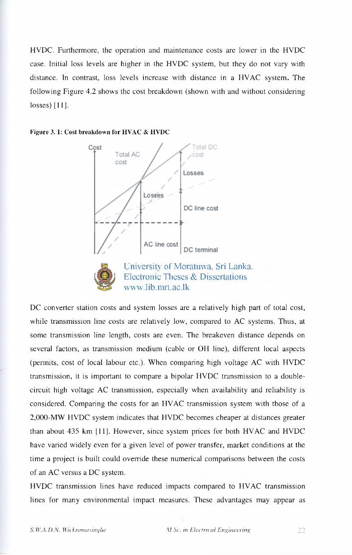
HVDC. Furthermore, the operation and maintenance costs are lower in the HVDC
case. Initial loss levels are higher in the HVDC system, but they do not vary with
distance. In contrast, loss levels increase with distance in a HVAC system. The
following Figure 4.2 shows the cost breakdown (shown with and without considering
losses) [11].
Figure 3 .1: Cost breakdown for HVAC & HVDC
DC converter station costs and system losses are a relatively high part of total cost,
while transmission line costs are relatively low, compared to AC systems. Thus, at
some transmission line length, costs are even. The breakeven distance depends on
several factors, as transmission medium (cable or OH line), different local aspects
(permits, cost of local labour etc.). When comparing high voltage AC with HVDC
transmission, it is important to compare a bipolar HVDC transmission to a double-
circuit high voltage AC transmission, especially when availability and reliability is
considered. Comparing the costs for an HVAC transmission system with those of a
2,000-MW HVDC system indicates that HVDC becomes cheaper at distances greater
than about 435 km [11], However, since system prices for both HVAC and HVDC
have varied widely even for a given level of power transfer, market conditions at the
time a project is built could override these numerical comparisons between the costs
of an AC versus a DC system.
HVDC transmission lines have reduced impacts compared to HVAC transmission
lines for many environmental impact measures. These advantages may appear as
S. W.A.D.N. Wick ran i a s in g he M.Sc. in Electrical Engineering 8

lower costs for mitigating such impacts when installing HVDC lines compared to
HVAC lines. If land use is taken as an overall measure of the comparative
environmental impacts of HVAC and HVDC transmission lines of the same relative
capacity, HVDC line impacts are roughly two-thirds of those of HVAC lines. Thus, a
transmission system that incorporates HVDC power transmission will, as a whole,
have reduced impacts compared to one that exclusively employs HVAC transmission
lines [8],
The main requirements to select an AC interconnection are synchronization and stable
operation of the two grids. It is desirable to go ahead with synchronous mode of
interconnection only when the grids of the countries are strong, disciplined, operating
in accordance with a uniform grid standard & under sound commercial principle. But
the major problem is the frequency fluctuation of the India's Southern region, which is
very large compared to that of Sri Lanka. This can affect badly on the Sri Lankan
system if they were connected with AC lines. Therefore the use of an asynchronous
mode of interconnection is required. That is it has to use HVDC technology. Also
since there is a sea portion between the two countries and the use of submarine cables
is beneficial, the use of HVDC will be the most suitable method. Therefore for the
interconnection of Madurai - Veyangoda the HVDC technology will be selected.
The HVDC technology offers two configurations, i.e. monopole and bipolar. At a
conceptual level, a monopole connection may be viewed as consisting of one path of
power flow carrying full power, while a bipolar connection may be viewed as
consisting of two parallel paths of power flows each carrying half of total power.
In a common configuration, called monopole, one of the terminals of the rectifier is
connected to earth ground. The other terminal, at a potential high above, or below,
ground, is connected to a transmission line. The earthed terminal may or may not be
connected to the corresponding connection at the inverting station by means of a
second conductor. If no metallic conductor is installed, current flows in the earth
between the earth electrodes at the two stations [12]. Therefore it is a type of Single
wire earth return. The issues surrounding earth-return current include,
• Electrochemical corrosion of long buried metal objects such as pipelines
• Underwater earth-return electrodes in seawater may produce chlorine or
otherwise affect water chemistry.
S. W.A.D.N. Wick ran i a s in g he M.Sc. in Electrical Engineering 23

• An unbalanced current path may result in a net magnetic field, which can
affect magnetic navigational compasses for ships passing over an underwater
cable.
These effects can be eliminated with installation of a metallic return conductor
between the two ends of the.monopole transmission line. Since one terminal of the
converters is connected to earth, the return conductor need not be insulated for the full
transmission voltage which makes it less costly than the high-voltage conductor. Use
of a metallic return conductor is decided based on economic, technical and
environmental factors.
Modern monopole systems for pure overhead lines carry typically 1500 MW. If
underground or underwater cables are used the typical value is 600 MW.
Most monopole systems are designed for future bipolar expansion. Transmission line
towers may be designed to carry two conductors, even if only one is used initially for
the monopole transmission system. The second conductor is unused, used as electrode
line or connected in parallel with the other.
In bipolar transmission a pair of conductors is used, each at a high potential with
respect to ground, in opposite polarity. Since these conductors must be insulated for
the full voltage, transmission line cost is higher than a monopole with a return
conductor. However, there are a number of advantages to bipolar transmission which
can make it the attractive option [12].
• Under normal load, negligible earth-current flows, as in the case of monopole
transmission with a metallic earth-return. This reduces earth return loss and
environmental effects.
• When a fault develops in a line, with earth return electrodes installed at each
end of the line, approximately half the rated power can continue to flow using
the earth as a return path, operating in monopole mode.
• Since for a given total power rating each conductor of a bipolar line carries
only half the current of monopole lines, the cost of the second conductor is
reduced compared to a monopole line of the same rating.
• In very adverse terrain, the second conductor may be carried on an
independent set of transmission towers, so that some power may continue to be
transmitted even if one line is damaged.
A bipolar system may also be installed with a metallic earth return conductor.
S. W.A.D.N. Wick ran i a s in g he M.Sc. in Electrical Engineering 24

Bipolar systems may carry as much as 3,000 MW at voltages of +/-533 kV.
Submarine cable installations initially commissioned as a monopole may be upgraded
with additional cables and operated as a bipolar. * .
A major disadvantage of the monopole configuration is that in case of a fault with any
of the converter/inverter or conductor/cable, the full power is lost, and this may
adversely affect the operation of the Sri Lankan system which is much smaller than
the Indian system. A bipolar system on the other hand provides a greater reliability as
it is essentially two independent systems operating in parallel.
When considering the reliability of the system the use of a bipolar HVDC connection
can be selected. But for the initial stage (short term) of transferring 500 MW it can
have a monopole connection of 500 MW and for the medium term of transferring
1,000 MW it can put up the second line of 500 MW with the first line to make it a
1,000 MW bipolar connection.
3.4 Voltage of the connection
In selection of the voltage both the technical and economical factors has to be
considered. The voltage selected has to be economical and depends on the cost of the
lines, cost of the apparatus such as transformers, circuit breakers, insulators, etc. This
cost increases very rapidly for voltages in the range of 230kV and above. With
increase in the power to be transmitted over long distances use of high voltages for
power transmission is considered.
The selected technology for the interconnection is HVDC and the amount of power to
be transmitted is 1000MW. In general to transmit 1000MW of power over a distance
of 450km or higher, it should use the voltages in the range of +300kV, +400kV or
+500kV. However a choice could be made out of the standard voltages which are used
on the two countries.
The highest transmission voltage use in Sri Lanka is 220kV (there are proposals for
the use of 400kV for the transmission but it has not studied up to now). And also the
grid substation at Veyangoda will be upgraded to 220kV by 2011. Generally for the
220kV transmission the maximum length of the line is about 300km. Since the length
of the interconnection between Madurai and Veyangoda is about 480km it has to go
for a voltage higher than 220kV.
S. W.A.D.N. Wick ran i a s in g he M.Sc. in Electrical Engineering 25

In India the transmission voltages are 765kV, 400kV, 200kV and 132kV and it has
experiences of +500kV and +400kV of HVDC transmission [3]. At present the
Madurai substation of India is a 400/220kV substation. Since there is a 400kV .bus at
Madurai and the maximum length of the line for the 400kV transmission is above
600km, it will be beneficial to select the 400kV as the voltage for the interconnection.
By selecting 400kV for the interconnection is can eliminate the cost of the
transformers at the Indian end, and also it will be an advantage for Sri Lanka when
they are upgrading to 400kV transmission system.
S. W.A.D.N. Wick ran i a s in g he M.Sc. in Electrical Engineering 26