30 nov, 2012 star korean conference 2012 - siemens · 30th nov, 2012 star korean conference 2012...
TRANSCRIPT
School of Mechanical Engineering, Yonsei University
Engine and Energy Research Group
Jungsoo Park
30th Nov, 2012
STAR Korean Conference 2012
Numerical Investigation on Performance & Emission Characteristics
of CI & SI Engine using 1D Cycle Simulation & DOE Method
Yonsei University - Engine and Energy Research Group
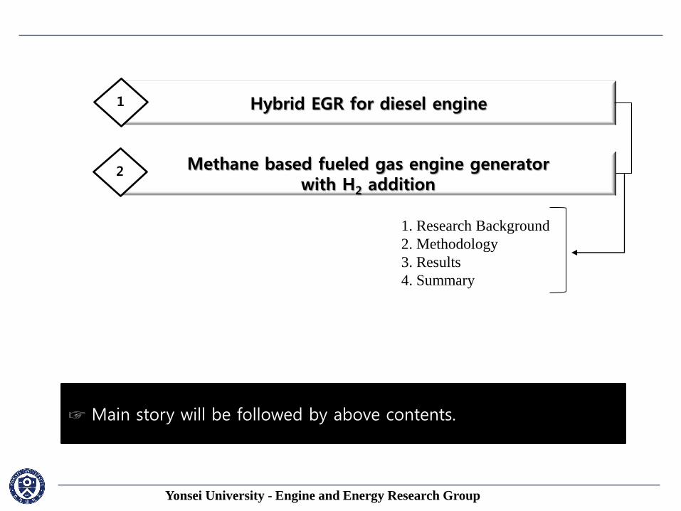
☞ This presentation is to introduce the methodology for numerical analysis of CI and SI engine in academic field by using GT-POWER. ☞ Main story will be followed by above contents.
Hybrid EGR for diesel engine 1
Methane based fueled gas engine generator with H2 addition
2
1. Research Background
2. Methodology
3. Results
4. Summary
Yonsei University - Engine and Energy Research Group
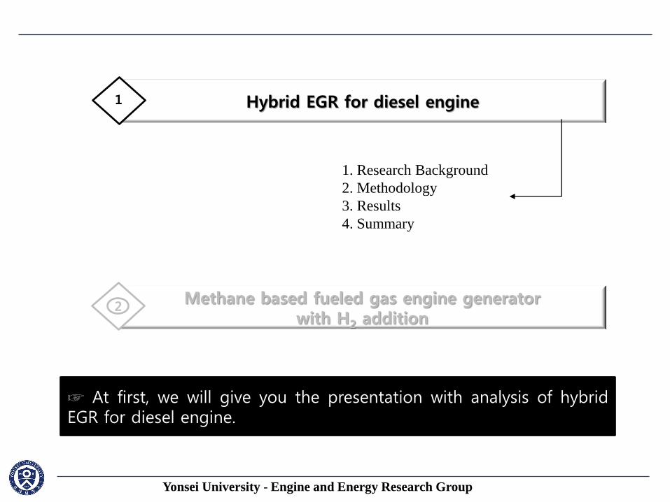
Hybrid EGR for diesel engine 1
Methane based fueled gas engine generator with H2 addition
2
1. Research Background
2. Methodology
3. Results
4. Summary
☞ At first, we will give you the presentation with analysis of hybrid EGR for diesel engine.
Yonsei University - Engine and Energy Research Group
1. Research Background
◆ Key technologies
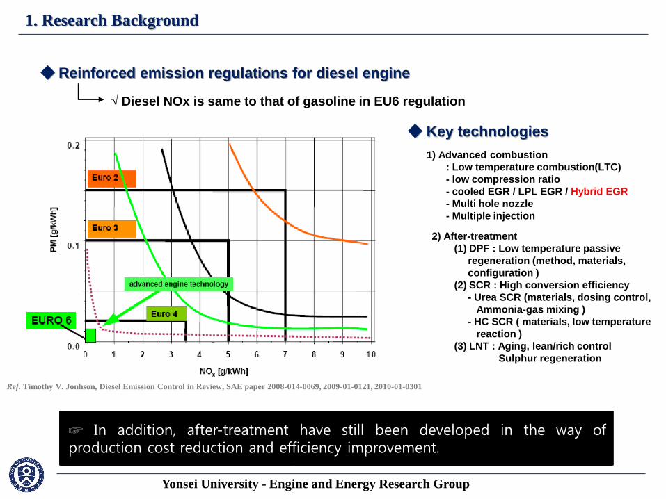
◆ Reinforced emission regulations for diesel engine
√ Diesel NOx is same to that of gasoline in EU6 regulation
Ref. Timothy V. Jonhson, Diesel Emission Control in Review, SAE paper 2008-014-0069, 2009-01-0121, 2010-01-0301
☞ Facing the reinforced emission regulations, advanced technologies to lower PM/NOx emissions with fuel economies in diesel engine.
1) Advanced combustion
: Low temperature combustion(LTC)
- low compression ratio
- cooled EGR / LPL EGR / Hybrid EGR
- Multi hole nozzle
- Multiple injection
☞ The advanced combustion technologies, such as HCCI, LTC, Injection strategies, etc. are the representative technologies. Especially for LTC, heavy EGR have been focused for a long time.
2) After-treatment
(1) DPF : Low temperature passive
regeneration (method, materials,
configuration )
(2) SCR : High conversion efficiency
- Urea SCR (materials, dosing control,
Ammonia-gas mixing )
- HC SCR ( materials, low temperature
reaction )
(3) LNT : Aging, lean/rich control
Sulphur regeneration
☞ In addition, after-treatment have still been developed in the way of production cost reduction and efficiency improvement.
Yonsei University - Engine and Energy Research Group
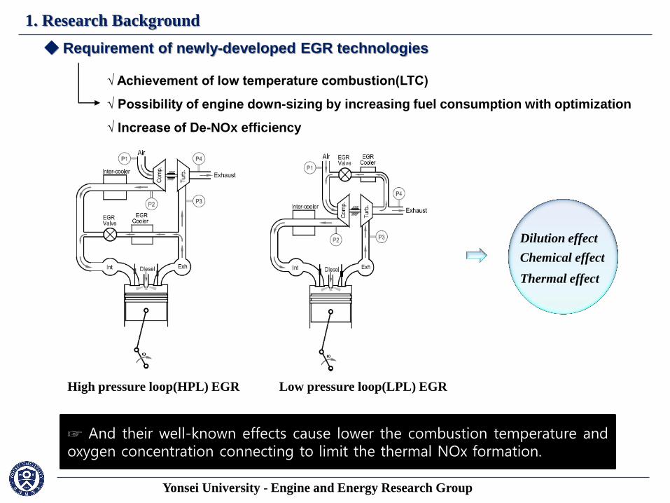
1. Research Background
√ Achievement of low temperature combustion(LTC)
√ Possibility of engine down-sizing by increasing fuel consumption with optimization
√ Increase of De-NOx efficiency
◆ Requirement of newly-developed EGR technologies
☞ Focusing on advantages of EGR system to achieve LTC,
High pressure loop(HPL) EGR Low pressure loop(LPL) EGR
there are two types of EGR systems, generally used.
Dilution effect
Chemical effect
Thermal effect
☞ And their well-known effects cause lower the combustion temperature and oxygen concentration connecting to limit the thermal NOx formation.
Yonsei University - Engine and Energy Research Group
1. Research Background
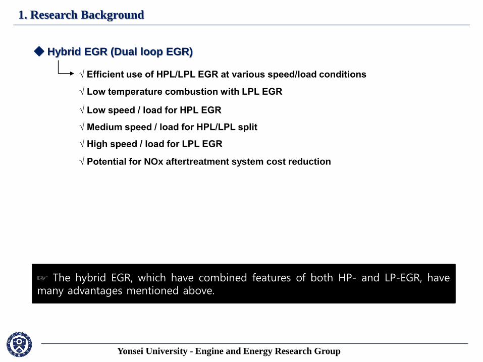
√ Efficient use of HPL/LPL EGR at various speed/load conditions
◆ Hybrid EGR (Dual loop EGR)
☞ The hybrid EGR, which have combined features of both HP- and LP-EGR, have many advantages mentioned above.
√ Low temperature combustion with LPL EGR
√ Low speed / load for HPL EGR
√ Medium speed / load for HPL/LPL split
√ High speed / load for LPL EGR
√ Potential for NOx aftertreatment system cost reduction
Yonsei University - Engine and Energy Research Group, EnERG
2. Material & method
Item Specification
Engine Volume 3000 cc
Cylinder arrangement 6cyl. , V- type
Bore * Stroke 84 * 89
Compression ratio 17.3
Connecting Rod Length 159 mm
Firing intervals 120 CA
Injection Type
EGR System
Common rail
HP- EGR System
Max. torque@rpm 240PS@3800rpm
Max. power@rpm 450N-m@1720~3500rpm
Case RPM BMEP (bar)
1 737 0.50
2 912 1.72
3 732 2.17
4 852 2.94
5 1273 2.07
6 1120 3.03
7 1362 2.66
8 1644 4.75
9 1636 4.66
10 1493 6.57
11 1674 7.34
12 1422 3.66
13 1556 9.93
14 1909 8.80
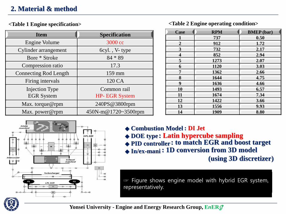
☞ The base engine specification is shown in table 1.
<Table 1 Engine specification>
☞ The base engine is equipped with VGT and HP-EGR system.
<Table 2 Engine operating condition>
☞ Table 2 shows operating conditions given by engine manufacturer. ☞ They are steady state points picked up from driving cycle and selected as validation points.
◆ Combustion Model
◆ DOE type
◆ PID controller
◆ In/ex-mani
☞ Based on the data including geometries at each engine part, injection rate and timing, target EGR and boost pressure, T and P, engine modeling was performed.
: DI Jet : Latin hypercube sampling
☞ The combustion model used was DI Jet which can provide NOx prediction. ☞ Latin hypercube sampling was used as fractional factorial DoE.
: to match EGR and boost target : 1D conversion from 3D model
(using 3D discretizer)
☞ PID control was applied to match target EGR rate and boost pressure. ☞ Figure shows engine model with hybrid EGR system, representatively.
Yonsei University - Engine and Energy Research Group, EnERG
2. Material & method
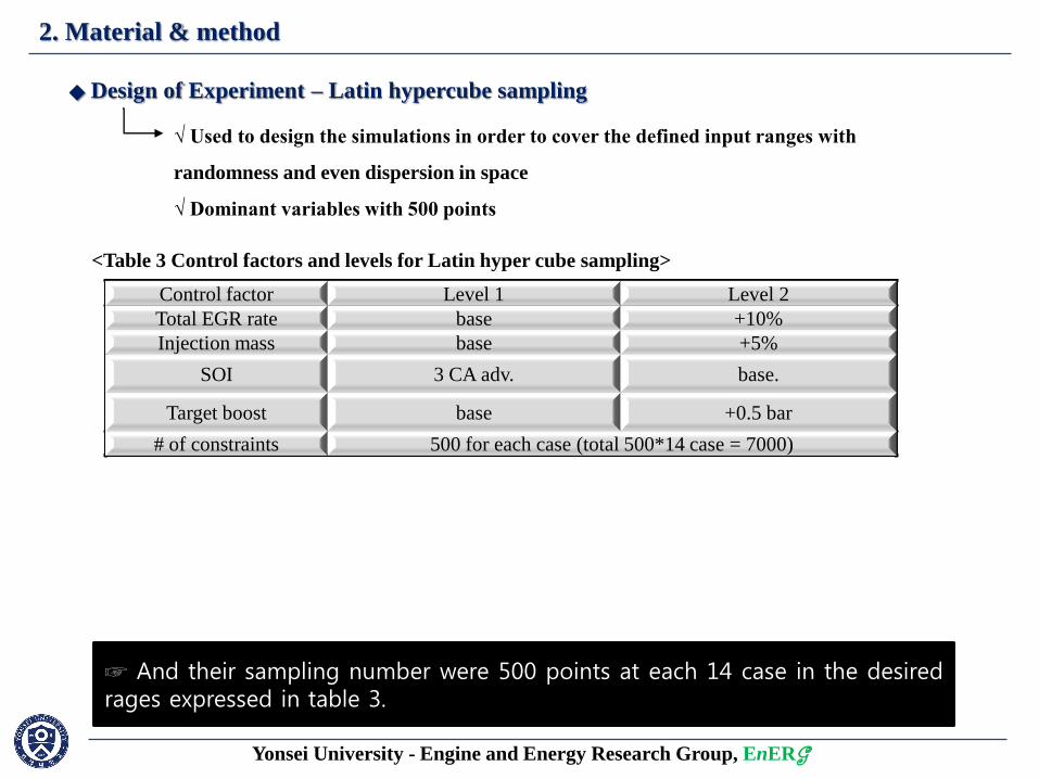
Control factor Level 1 Level 2
Total EGR rate base +10%
Injection mass base +5%
SOI 3 CA adv. base.
Target boost base +0.5 bar
# of constraints 500 for each case (total 500*14 case = 7000)
◆ Design of Experiment – Latin hypercube sampling
√ Used to design the simulations in order to cover the defined input ranges with
randomness and even dispersion in space
√ Dominant variables with 500 points
☞ Target EGR rate, injection mass, start of injection and target boost pressure were selected as independent variables for DoE parameter.
<Table 3 Control factors and levels for Latin hyper cube sampling>
☞ And their sampling number were 500 points at each 14 case in the desired rages expressed in table 3.
Yonsei University - Engine and Energy Research Group, EnERG
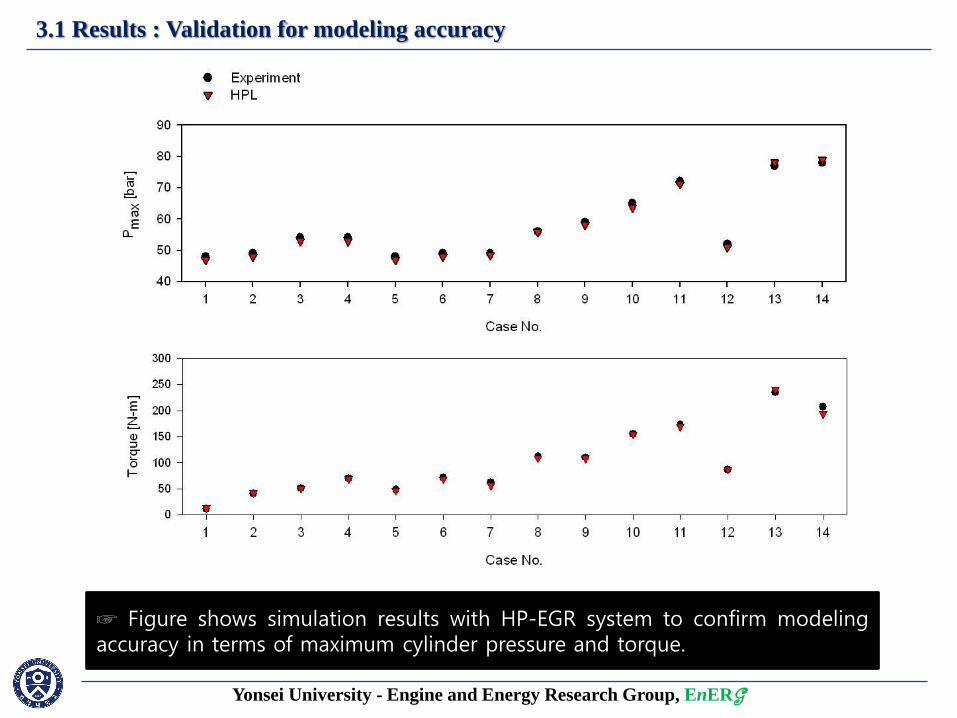
3.1 Results : Validation for modeling accuracy
☞ Figure shows simulation results with HP-EGR system to confirm modeling accuracy in terms of maximum cylinder pressure and torque.
Yonsei University - Engine and Energy Research Group, EnERG
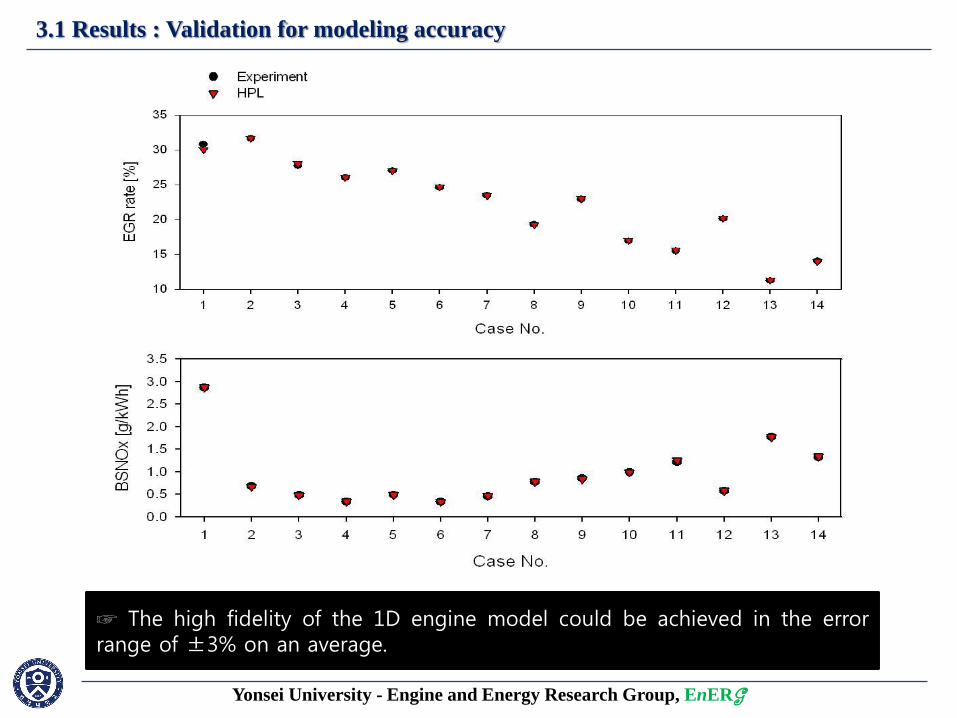
3.1 Results : Validation for modeling accuracy
☞ Figure shows simulation results with HP-EGR system to confirm modeling accuracy in terms of actual EGR rate and BSNOx. ☞ The high fidelity of the 1D engine model could be achieved in the error range of ±3% on an average.
Yonsei University - Engine and Energy Research Group, EnERG
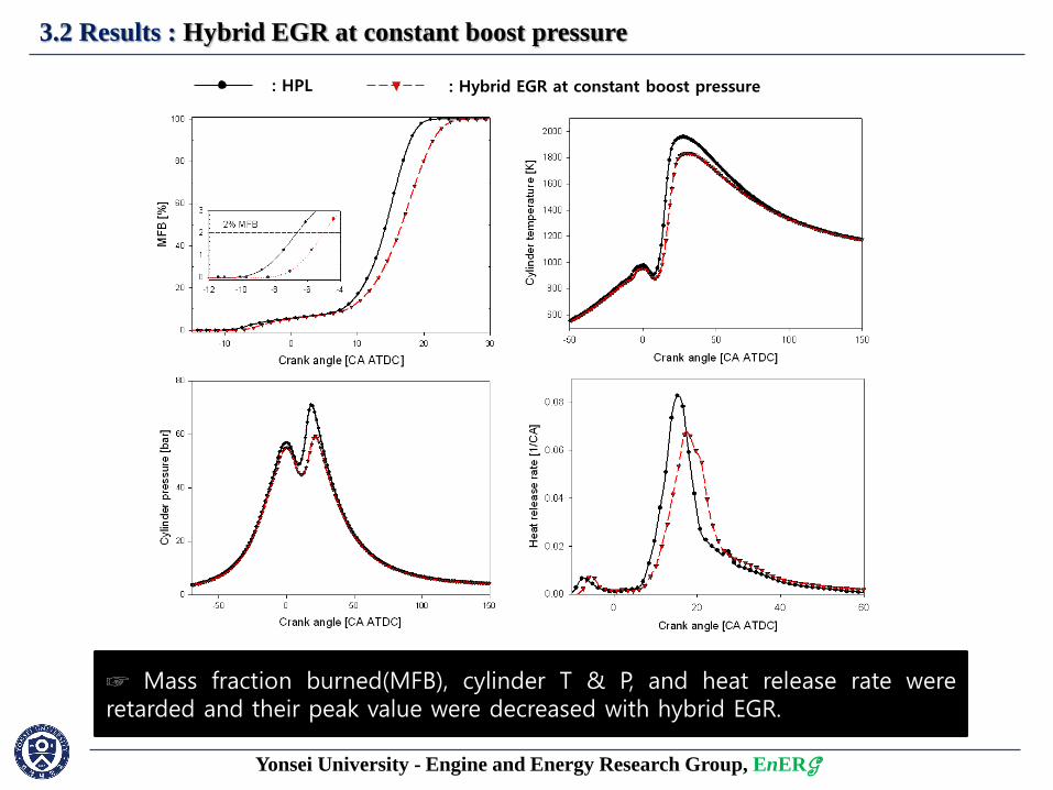
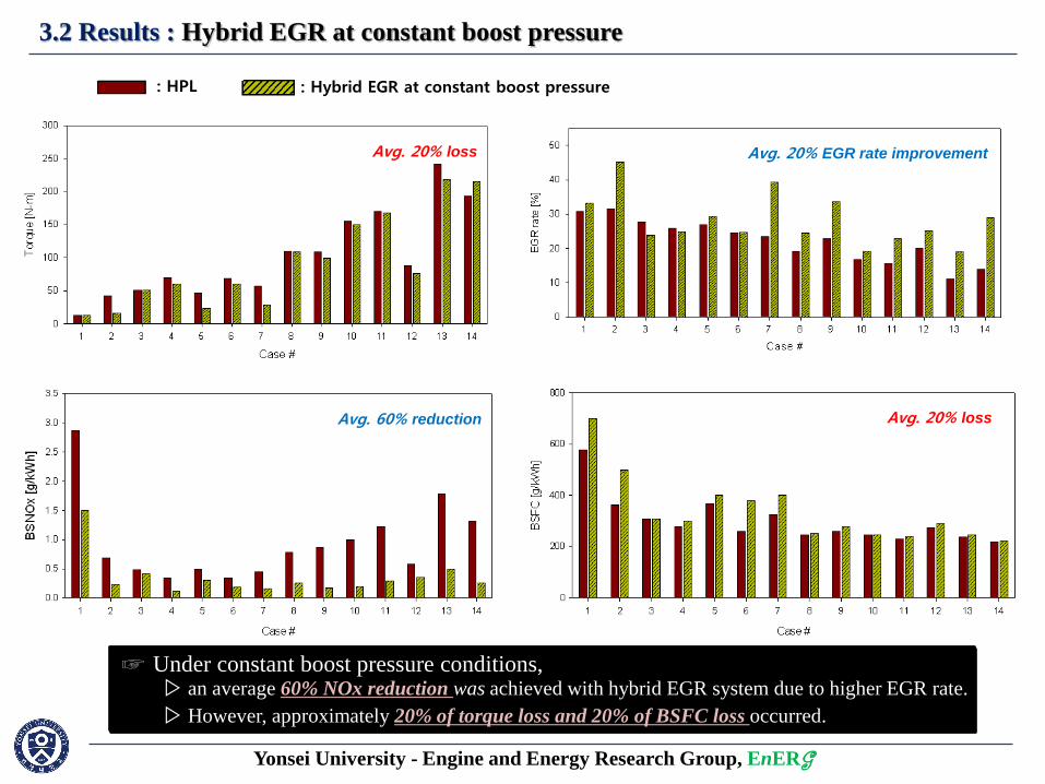
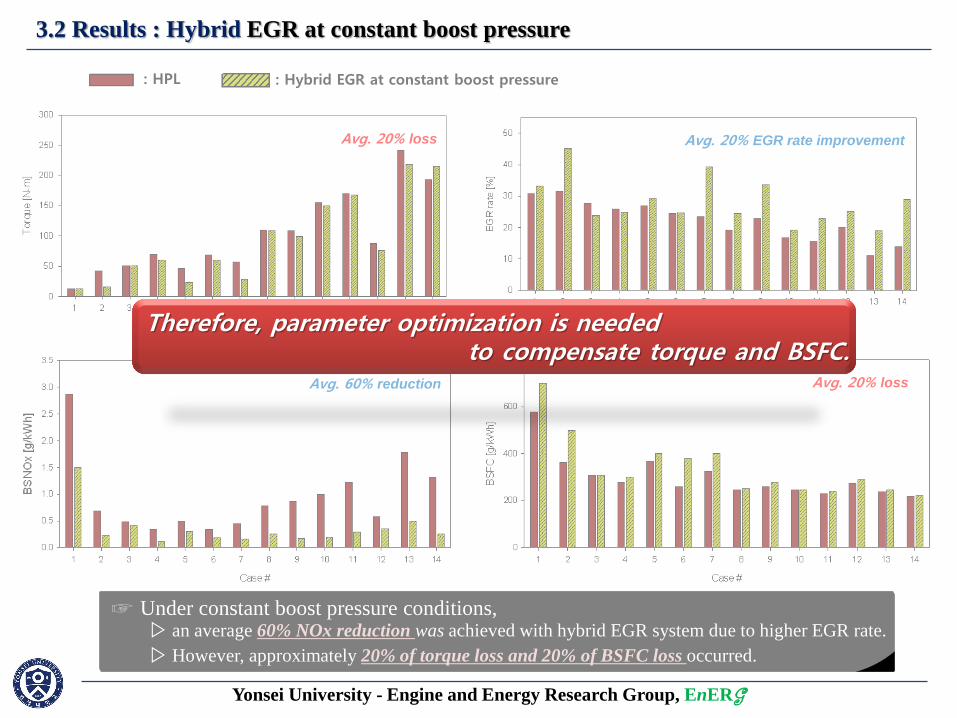
3.2 Results : Hybrid EGR at constant boost pressure
: HPL : Hybrid EGR at constant boost pressure
☞ From the base model, combustion characteristics under hybrid EGR system was obtained maintaining boost pressure. ☞ Mass fraction burned(MFB), cylinder T & P, and heat release rate were retarded and their peak value were decreased with hybrid EGR.
Yonsei University - Engine and Energy Research Group, EnERG
3.2 Results : Hybrid EGR at constant boost pressure
: Hybrid EGR at constant boost pressure : HPL
☞ The above plots represent comparison between HP- and hybrid EGR under constant boost pressure.
☞ Under constant boost pressure conditions,
Avg. 20% EGR rate improvement
Avg. 60% reduction
▷ an average 60% NOx reduction was achieved with hybrid EGR system due to higher EGR rate.
Avg. 20% loss
Avg. 20% loss
▷ However, approximately 20% of torque loss and 20% of BSFC loss occurred.
Therefore, parameter optimization is needed to compensate torque and BSFC.
Yonsei University - Engine and Energy Research Group, EnERG
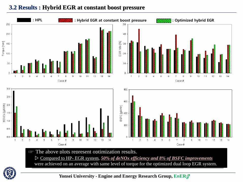
3.2 Results : Hybrid EGR at constant boost pressure
: HPL : Hybrid EGR at constant boost pressure : Optimized hybrid EGR
☞ The above plots represent optimization results.
▷ Compared to the hybrid EGR system under constant boost pressure,
8% of torque and 15% BSFC improvement were achieved on an average. ▷ Compared to HP- EGR system, 50% of deNOx efficiency and 8% of BSFC improvements
were achieved on an average with same level of torque for the optimized dual loop EGR system.
Yonsei University - Engine and Energy Research Group, EnERG
4. Summary
▪ To compensate torque and fuel consumption, independent variables, such as start of injection and
injection mass, were selected as additional control factors using Latin hypercube sampling.
Compared to the dual loop EGR system under constant boost pressure, 8% of torque and 15% BSFC
improvement were achieved on an average.
▪ Compared to HPL EGR system, 50% of deNOx efficiency and 8% of BSFC improvements were
achieved on an average with same level of torque for the optimized dual loop EGR system.
▪ An engine model for the HPL EGR was developed based on the experimental data at 14 operating
conditions. The calibrated simulations showed within ±3% accuracy compared to the experimental
results.
▪ Under constant boost pressure conditions, an average 60% NOx reduction was achieved in the dual
loop EGR system compared to the results under the HPL system. However, approximately 20% of
torque loss and 20% of BSFC loss occurred respectively.
☞ You can meet more detailed results from our published paper as follows :
▷ Park et al. (2009), Asia Pacific Automotive Engineering Conference; 26-28 Oct,2009, APAC15-356.
▷ Park et al. (2010), International journal of automotive technology, 2010;11:617-23.
▷ Park et al. (2010), Transactions of KSAE, 2010;18:136-44.
Yonsei University - Engine and Energy Research Group
Hybrid EGR for diesel engine 1
Methane based fueled gas engine generator with H2 addition
2
1. Research Background
2. Methodology
3. Results
4. Summary
☞ At this part, 1D engine analysis with gas fueled engine generator will be introduced.
Yonsei University - Engine and Energy Research Group
1. Research Background
Substance Density (kg/l) Ignition Temperature(℃) Specific heat
of evaporation(kJ/kg) Net calorific value
(MJ/kg)
Ignition limit (by vol% of gas in air)
Lower Upper
Gasoline 0.720-0.775 ~300 380~500 41.2~41.9 0.6 8
Diesel 0.820-0.845 ~250 ~250 42.9~43.1 0.6 7.5
Hydrogen 0.090x10⁻³ 560 - 120 4 77
Propane 2x10⁻³ 470 - 46.3 1.9~9.5 15.6
DME 2.05x10⁻³ 235 - 28.8 3.4~18.8 9
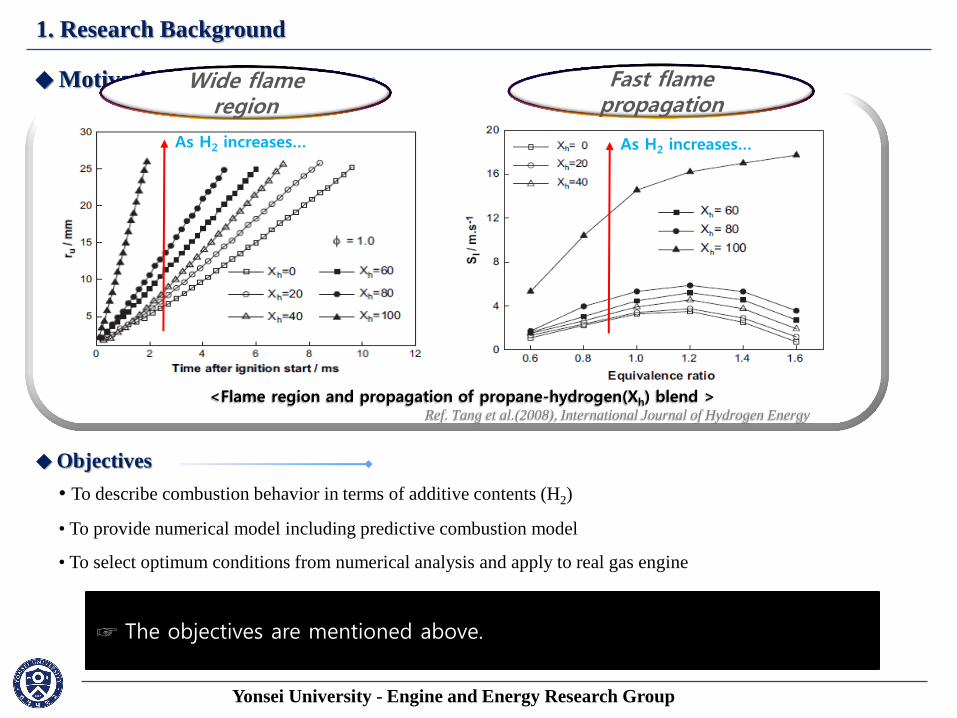
◆ Motivation
• Increasing needs of biogas and hydrogen share
☞ Increasing needs for alternative fuel, biogas, hydrogen and its blend have been focused.
• Hydrogen-hydrocarbon blends >> Improving combustion behavior on engine system
☞ It is well-known that hydrogen improves the combustion behavior
Wide flame region
Fast flame propagation
As H2 increases… As H2 increases…
<Flame region and propagation of propane-hydrogen(Xh) blend > Ref. Tang et al.(2008), International Journal of Hydrogen Energy
having with its wide flame region and fast flame propagation.
☞ Motivated by background, we tried to model the 1D-gas engine simply by GT-POWER. ☞ The objectives are mentioned above.
◆ Objectives
• To describe combustion behavior in terms of additive contents (H2)
• To provide numerical model including predictive combustion model
• To select optimum conditions from numerical analysis and apply to real gas engine
Yonsei University - Engine and Energy Research Group, EnERG
2. Material & method
Yonsei University - Engine and Energy Research Group, EnERG
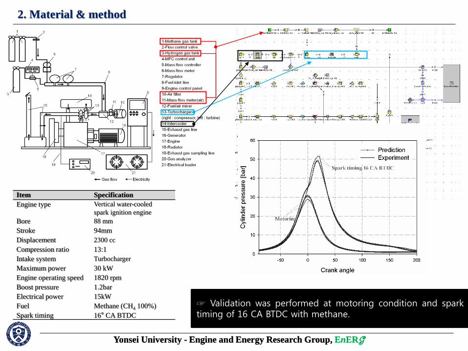
Item Specification
Engine type Vertical water-cooled
spark ignition engine
Bore 88 mm
Stroke 94mm
Displacement 2300 cc
Compression ratio 13:1
Intake system Turbocharger
Maximum power 30 kW
Engine operating speed 1820 rpm
Boost pressure 1.2bar
Electrical power 15kW
Fuel Methane (CH4 100%)
Spark timing 16° CA BTDC
☞ Base engine is 2300 cc SI engine generator fueled with CNG. ☞ Experiment was performed with methane at 16 CA BTDC of spark timing and 1.2 of lambda. ☞ Based on the engine data, 1D-engine model was developed as shown in figure. ☞ Validation was performed at motoring condition and spark timing of 16 CA BTDC with methane.
Yonsei University - Engine and Energy Research Group, EnERG
2. Material & method
Yonsei University - Engine and Energy Research Group, EnERG
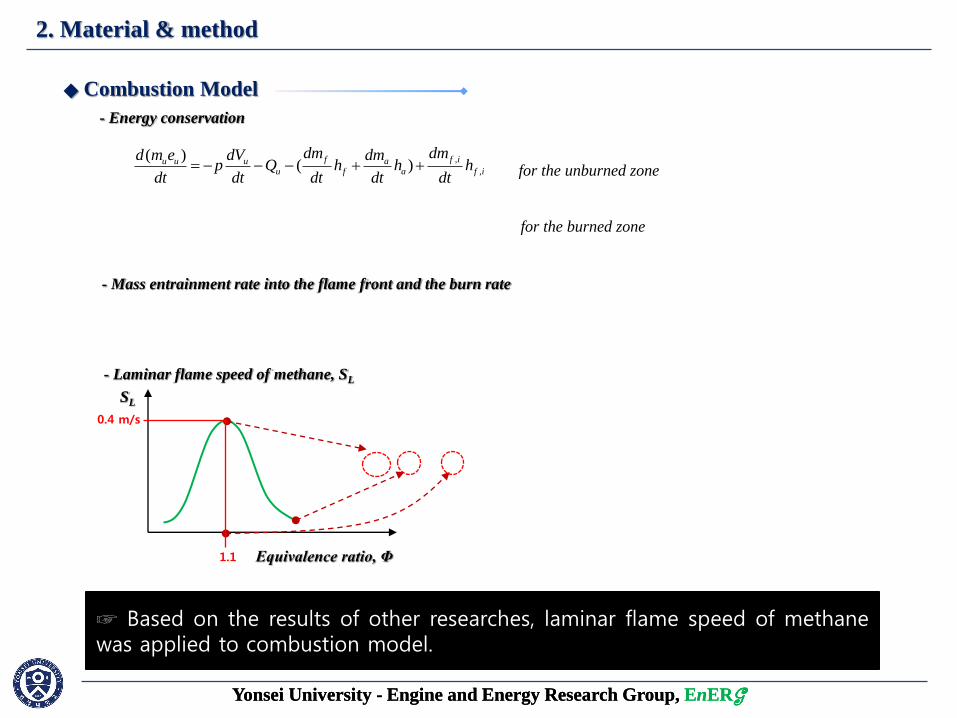
- Energy conservation
,
,
( )( )
f f iu u u au f a f i
dm dmd m e dV dmp Q h h h
dt dt dt dt dt
( )( )
fb b b ab f a
dmd m e dV dmp Q h h
dt dt dt dt
for the unburned zone
for the burned zone
- Mass entrainment rate into the flame front and the burn rate
( )eu e T L
dMA S S
dt
( )b e bdM M M
dt
LS
◆ Combustion Model
☞ The combustion model was SI turbulent model which was provided from GT-POWER.
- Laminar flame speed of methane, SL
☞ The most important parameter in this combustion model is laminar flame speed. ☞ To describe the methane combustion, user have to define and determine the laminar flame speed.
SL
Equivalence ratio, Φ
☞ The general shape of laminar flame speed for fuel have a parabolic type.
2 0.77( ( ) ) ( ) ( ) (1 2.06( ) )DEMuL m m
ref ref
T pS B B Dilution
T p
0.4 m/s
1.1
☞ Based on the results of other researches, laminar flame speed of methane was applied to combustion model.
Yonsei University - Engine and Energy Research Group, EnERG
2. Material & method
Yonsei University - Engine and Energy Research Group, EnERG
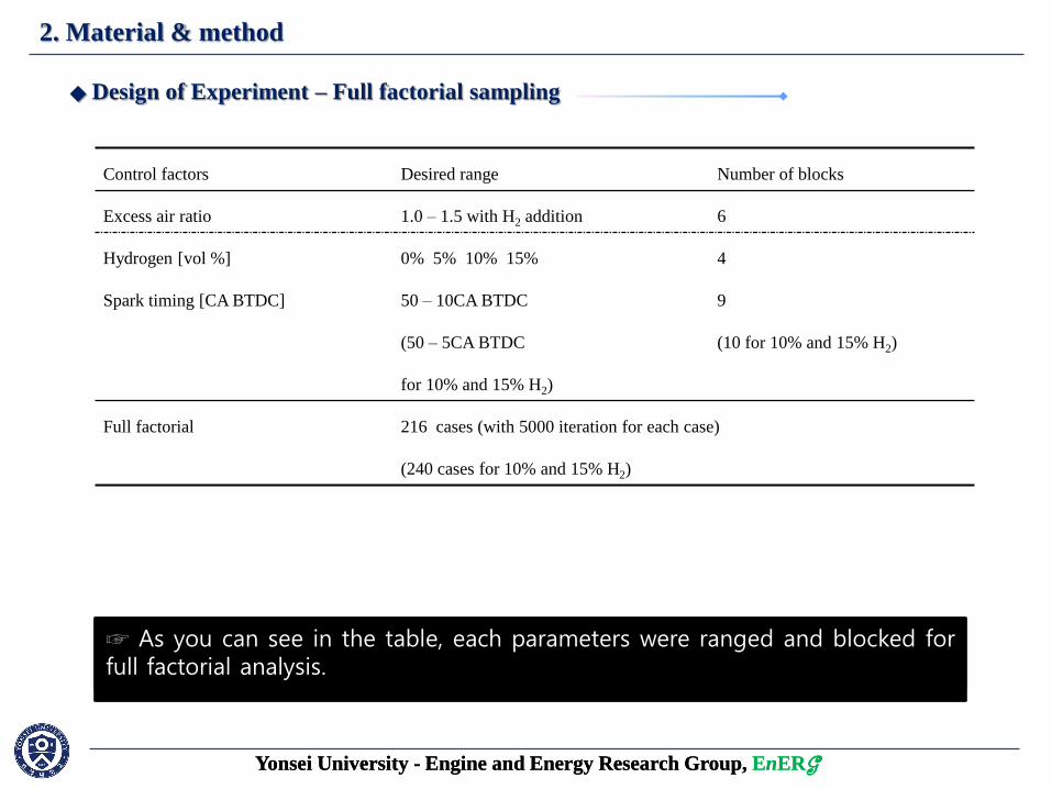
Control factors Desired range Number of blocks
Excess air ratio 1.0 – 1.5 with H2 addition 6
Hydrogen [vol %] 0% 5% 10% 15% 4
Spark timing [CA BTDC] 50 – 10CA BTDC
(50 – 5CA BTDC
for 10% and 15% H2)
9
(10 for 10% and 15% H2)
Full factorial 216 cases (with 5000 iteration for each case)
(240 cases for 10% and 15% H2)
◆ Design of Experiment – Full factorial sampling
☞ For DoE analysis, full factorial method was applied. ☞ Excess air ratio, hydrogen contents and spark timing were selected as independent variables. ☞ As you can see in the table, each parameters were ranged and blocked for full factorial analysis.
Yonsei University - Engine and Energy Research Group, EnERG
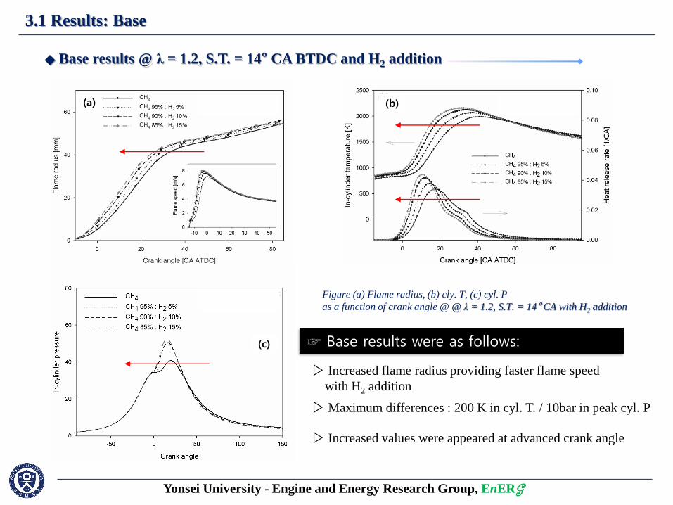
3.1 Results: Base
◆ Base results @ λ = 1.2, S.T. = 14° CA BTDC and H2 addition
☞ Base results were as follows:
(a)
▷ Increased flame radius providing faster flame speed
with H2 addition
Figure (a) Flame radius, (b) cly. T, (c) cyl. P
as a function of crank angle @ @ λ = 1.2, S.T. = 14° CA with H2 addition
(c)
(b)
▷ Maximum differences : 200 K in cyl. T. / 10bar in peak cyl. P
▷ Increased values were appeared at advanced crank angle
Yonsei University - Engine and Energy Research Group, EnERG
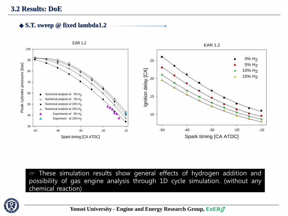
3.2 Results: DoE
EAR 1.2
Spark timing [CA ATDC]
-50 -40 -30 -20 -10
Pea
k c
ylin
de
r p
ressu
re [
ba
r]
30
40
50
60
70
80
90
100
Numerical analysis w/ 0% H2
Numerical analysis w/ 5% H2
Numerical analysis w/ 10% H2
Numerical analysis w/ 15% H2
Experiments w/ 0% H2
Experiment w/ 10% H2
◆ S.T. sweep @ fixed lambda1.2
☞ From DoE results, peak cylinder pressures were compared to 7 experimental points as a function of spark timing at fixed λ. ☞ Although there were a few experimental points, results have good agreements in the range of ±5% accuracy on an average.
EAR 1.2
Spark timing [CA ATDC]
-50 -40 -30 -20 -10
Ign
itio
n d
ela
y [C
A]
10
15
20
25 0% H2
5% H2
10% H2
15% H2
☞ Peak cylinder pressures were increased with hydrogen addition. ☞ Furthermore, Ignition delay were shortened affected by hydrogen addition.
☞ These simulation results show general effects of hydrogen addition and possibility of gas engine analysis through 1D cycle simulation. (without any chemical reaction)
Yonsei University - Engine and Energy Research Group, EnERG
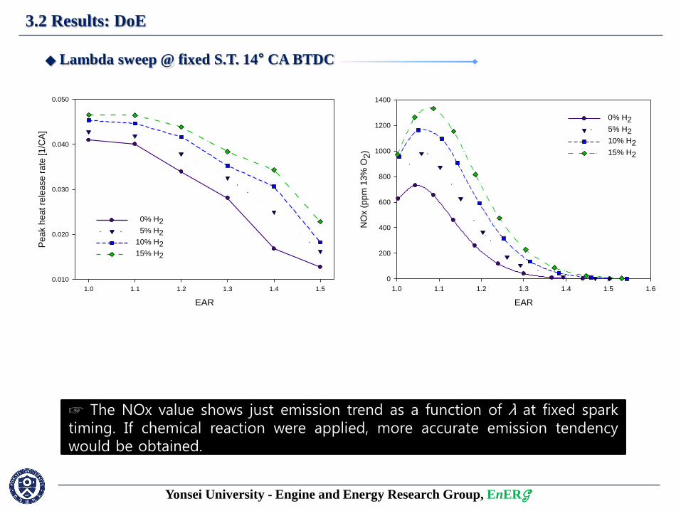
3.2 Results: DoE
EAR
1.0 1.1 1.2 1.3 1.4 1.5 1.6
NO
x (
ppm
13%
O2)
0
200
400
600
800
1000
1200
1400
0% H2
5% H2
10% H2
15% H2
EAR
1.0 1.1 1.2 1.3 1.4 1.5
Peak h
eat re
lease r
ate
[1/C
A]
0.010
0.020
0.030
0.040
0.050
0% H2
5% H2
10% H2
15% H2
◆ Lambda sweep @ fixed S.T. 14° CA BTDC
☞ Above plot represent increase of heat release rate and NOx under hydrogen addition. (due to increased combustion temperature)
☞ The NOx value shows just emission trend as a function of λ at fixed spark timing. If chemical reaction were applied, more accurate emission tendency would be obtained.
Yonsei University - Engine and Energy Research Group, EnERG
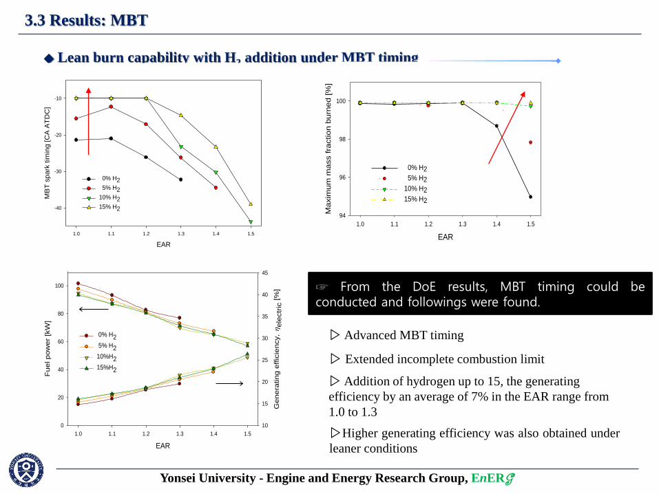
3.3 Results: MBT
◆ Lean burn capability with H2 addition under MBT timing
☞ From the DoE results, MBT timing could be conducted and followings were found.
EAR
1.0 1.1 1.2 1.3 1.4 1.5
Fuel pow
er
[kW
]
0
20
40
60
80
100
Genera
ting e
ffic
iency,
ele
ctr
ic [%
]
10
15
20
25
30
35
40
45
0% H2
5% H2
10%H2
15%H2
▷ Addition of hydrogen up to 15, the generating
efficiency by an average of 7% in the EAR range from
1.0 to 1.3
▷Higher generating efficiency was also obtained under
leaner conditions
EAR
1.0 1.1 1.2 1.3 1.4 1.5
MB
T s
park
tim
ing [
CA
AT
DC
]
-40
-30
-20
-10
0% H2
5% H2
10% H2
15% H2
▷ Advanced MBT timing
EAR
1.0 1.1 1.2 1.3 1.4 1.5
Maxim
um
mass f
raction b
urn
ed [
%]
94
96
98
100
0% H2
5% H2
10% H2
15% H2
▷ Extended incomplete combustion limit
Yonsei University - Engine and Energy Research Group, EnERG
4. Summary
• Varying spark timing, it is implied that ignition delay can be suggested as combustion
control strategies of methane-based gas with H2 additives.
• At MBT conditions with H2 addition, lean operation limit could be extended.
• Gas engine fueled with Methane-based gas was modelled by using 1D simulation code
describing experimental conditions.
• The fundamental effects of H2 at a fixed EAR of 1.2 and spark timing of 14° CA BTDC
were investigated. The heat release rate, cylinder temperature, and cylinder pressure
increased with H2 addition.
☞ You can meet more detailed results from our published paper as follows :
▷ Park et al. (2011), International Journal of Hydrogen Energy; 2011;36:5153-62.
▷ Park et al. (2012), 5th International Conference on Sustainable Energy & Environmental Protection; 5-8 June, , 2012.
Thank you
for your attention
Yonsei University –
Engine and Energy Research Group