3.0 design of structures, components, equipment and …
TRANSCRIPT

FSAR: Chapter 3.0
3.0 DESIGN OF STRUCTURES, COMPONENTS, EQUIPMENT AND SYSTEMS
This chapter of the U.S. EPR FSAR is incorporated by reference, with the departures and supplements described in the following sections.
CCNPP Unit 3 3–1 Rev. 5© 2007 UniStar Nuclear Services, LLC. All rights reserved.
COPYRIGHT PROTECTED

FSAR: Chapter 3.0 Compliance with Nuclear Regulatory Commission General Design Criteria
3.1 COMPLIANCE WITH NUCLEAR REGULATORY COMMISSION GENERAL DESIGN CRITERIA
This section of the U.S. EPR FSAR is incorporated by reference, with the supplements described in the following sections.
3.1.1 OVERALL REQUIREMENTS
3.1.1.1 Criterion 1 – Quality Standards and Records
No departures or supplements.
3.1.1.1.1 U.S. EPR Compliance
The U.S. EPR FSAR includes the following COL Item in Section 3.1.1.1.1:
A COL applicant that references the U.S. EPR design certification will identify the site-specific QA Program Plan that demonstrates compliance with GDC 1.
This COL Item is addressed as follows:
{The QA Program is provided in UniStar Nuclear Topical Report No. UN-TR-06-001-A, “Quality Assurance Program Description,” (QAPD) (UniStar, 2007) as described in Chapter 17.}
The QAPD is applicable to the siting, design, fabrication, construction (including pre-operational testing), operation (including testing), maintenance and modification of the facility. The QAPD demonstrates compliance with GDC 1.
3.1.1.2 Criterion 2 – Design Bases for Protection Against Natural Phenomena
No departures or supplements.
3.1.1.3 Criterion 3 – Fire Protection
No departures or supplements.
3.1.1.4 Criterion 4 – Environmental and Missile Design Bases
No departures or supplements.
3.1.1.5 Criterion 5 – Sharing of Structures, Systems, and Components
No departures or supplements.
3.1.1.5.1 U.S. EPR Compliance
{CCNPP Unit 3 shares the following structures, systems, and components with CCNPP Units 1 and 2:
Offsite transmission system – The CCNPP Unit 3 substation is electrically integrated with the existing CCNPP Units 1 and 2, 500 kV substation. While the offsite transmission system is shared between CCNPP Unit 3 and CCNPP Units 1 and 2, CCNPP Unit 3 has onsite AC and DC systems that are dedicated to its use. The offsite AC power sources are described in more detail in Section 8.2, and the onsite power sources are described in Section 8.3.
Existing Chesapeake Bay intake channel and embayment consists of the:
CCNPP Unit 3 3–2 Rev. 5© 2007 UniStar Nuclear Services, LLC. All rights reserved.
COPYRIGHT PROTECTED
FSAR: Chapter 3.0 Compliance with Nuclear Regulatory Commission General Design Criteria
Existing CCNPP Units 1 and 2 intake channel that extends 4,500 ft (1,380 m) offshore.
Existing embayment that is defined by a deep curtain wall.
CCNPP Unit 3 intake channel.
Non-safety-related CWS Makeup Water Intake Structure.
Safety-related Ultimate Heat Sink (UHS) Makeup Water Intake Structure.
CCNPP Units 1 and 2 and CCNPP Unit 3 share the CCNPP Units 1 and 2 intake channel and embayment. While the CCNPP Unit 3 CWS Makeup Water Intake Structure, UHS Makeup Water Intake Structure, and UHS Intake Channel are located within the embayment, they are structurally independent of the CCNPP Units 1 and 2 intake structures, and are located in a different part of the embayment. The UHS is described in more detail in Section 9.2.5. The CWS System is described in more detail in Section 10.5
Meteorological tower – The meteorological tower provides meteorological data to CCNPP Units 1 and 2 and CCNPP Unit 3 to support operational and emergency response purposes. It is described in more detail in Section 2.3.3.
Emergency Operations Facility (EOF) – The EOF is described in more detail in Part 5 of the COL application.
The structures, systems, and components are designed such that an accident in one unit would not impair their ability to perform their function for any other unit.}
3.1.2 PROTECTION BY MULTIPLE FISSION PRODUCT BARRIERS
No departures or supplements.
3.1.3 PROTECTION AND REACTIVITY CONTROL SYSTEMS
No departures or supplements.
3.1.4 FLUID SYSTEMS
No departures or supplements.
3.1.5 REACTOR CONTAINMENT
No departures or supplements.
3.1.6 FUEL AND REACTIVITY CONTROL
No departures or supplements.
3.1.7 REFERENCES
{UniStar, 2007. Letter from R. M. Krich, UniStar Nuclear, to U. S. Nuclear Regulatory Commission, “UniStar Nuclear, NRC Project No. 746, Submittal of the Published UniStar Topical Report No. UN-TR-06-001-A, ‘Quality Assurance Program Description,’ Revision 0,” dated April 9, 2007.}
CCNPP Unit 3 3–3 Rev. 5© 2007 UniStar Nuclear Services, LLC. All rights reserved.
COPYRIGHT PROTECTED

FSAR: Chapter 3.0 Classification of Structures, Systems, and Components
3.2 CLASSIFICATION OF STRUCTURES, SYSTEMS, AND COMPONENTS
This section of the U.S. EPR FSAR is incorporated by reference, with the supplements described in the following sections.
3.2.1 SEISMIC CLASSIFICATION
The U.S. EPR FSAR includes the following COL Item in Section 3.2.1:
A COL applicant that references the U.S. EPR design certification will identify the seismic classification of applicable site-specific SSCs that are not identified in U.S. EPR FSAR Table 3.2.2-1.
This COL Item is addressed as follows:
The seismic classifications for applicable site-specific structures, systems, and components (SSCs) are provided in Table 3.2-1.
{U.S. EPR FSAR Section 3.2.1 states: “The seismic classification of the U.S. EPR SSCs uses the following categories: Seismic Category I, Seismic Category II, radwaste seismic, conventional seismic, and non-seismic.” As described in Section 3.2.1.2, CCNPP Unit 3 utilizes an additional seismic classification: Seismic Category II-SSE. This classification is applicable to Fire Protection SSCs that support equipment required to achieve safe shutdown following a seismic event.}
3.2.1.1 Seismic Category I
No departures or supplements.
3.2.1.2 Seismic Category II
{In addition to the Seismic Category II classification defined in U.S. EPR FSAR Section 3.2.1, CCNPP Unit 3 utilizes a seismic classification of Seismic Category II-SSE. This designation is utilized to address Fire Protection SSC that are required to remain functional during and following a seismic event to support equipment required to achieve safe shutdown in accordance with Regulatory Guide 1.189 (NRC, 2007). Sections 3.7.2.8 and 3.7.3.12 discuss the methods for analysis of these components.
Some SSCs that perform no safety-related function could, if they failed under seismic loading, prevent or reduce the functional capability of a Seismic Category I SSC, Seismic Category II-SSE SSC, or cause incapacitating injury to main control room occupants during or following an SSE. These non-safety-related SSCs are classified as Seismic Category II.
SSCs classified as Seismic Category II are designed to withstand SSE seismic loads without incurring a structural failure that permits deleterious interaction with any Seismic Category I SSC or Seismic Category II-SSE SSC, or that could result in injury to main control room occupants. The seismic design criteria that apply to Seismic Category II SSCs are addressed in Section 3.7.}
3.2.1.3 Radwaste Seismic
No departures or supplements.
3.2.1.4 Conventional Seismic
No departures or supplements.
CCNPP Unit 3 3–4 Rev. 5© 2007 UniStar Nuclear Services, LLC. All rights reserved.
COPYRIGHT PROTECTED

FSAR: Chapter 3.0 Classification of Structures, Systems, and Components
3.2.1.5 Non-Seismic
No departures or supplements.
3.2.2 SYSTEM QUALITY GROUP CLASSIFICATION
The U.S. EPR FSAR includes the following COL Item in Section 3.2.2:
A COL applicant that references the U.S. EPR design certification will identify the quality group classification of site-specific SSCs that are not identified in this table (U.S. EPR FSAR Table 3.2.2-1).
This COL Item is addressed as follows:
The quality group classification of site-specific SSCs is provided in Table 3.2-1.
3.2.3 REFERENCES
{NRC, 2007. Fire Protection for Nuclear Power Plants, Regulatory Guide 1.189, Revision 1, U.S. Nuclear Regulatory Commission, March 2007.}
CCNPP Unit 3 3–5 Rev. 5© 2007 UniStar Nuclear Services, LLC. All rights reserved.
COPYRIGHT PROTECTED

FSAR: Chapter 3.0 Classification of Structures, Systems, and Components
Table 3.2-1—{Classification Summary for Site-Specific SSCs} (Page 1 of 7)
KKS System or Component Code
System or Component Description Sa
fety
Clas
sific
atio
n(N
ote
1)
Qua
lity
Gro
upCl
assi
ficat
ion
Seis
mic
Cat
egor
y(N
ote
2) 10CFR50 Appendix B Program Lo
cati
on(N
ote
3)
Comments/ Commercial Code
Table 3.2.2-1 of the U.S. EPR FSAR contains the following conceptual design information for the SM, SN, Cranes, Hoists, and Elevators category for: UKE, Access Building, and UBZ, Buried Conduit Duct Bank.[[UKE Access Building NS-AQ N/A CS No UKEUBZ Buried Conduit Duct Bank S N/A I Yes UBZ]]The U.S. EPR FSAR descriptions provided in U.S. EPR FSAR Table 3.2.2-1 regarding the SM, SN, Cranes, Hoists, and Elevators category for: UKE, Access Building, and UBZ, Buried Conduit Duct Bank are applicable to CCNPP Unit 3, and are incorporated by reference.PE, PEB, PED UHS Makeup Water System30PED 10/20/30/40/AP001
UHS Makeup Water Pumps S C I Yes UPB ASME III ANSI/HI 2.3
30PED 10/20/30/40/AH001
UHS Makeup Water Pump Motors (30 PED 10/20/30/40/ AH001)
S C I Yes UPB IEEE/NEMA
Piping (30PED 10/20/30/40) to Cooling Tower
S C I Yes UPB, UZT
ASME III
30PED 10/20/30/40/AT 001/AT002
Discharge Strainer S C I Yes UPB ASME III
30PED 10/20/30/40/ AA001, 30 PED 10/20/30/40/ AA005
Isolation Valves S C I Yes UPB/ UZT
ASME III/IEEE
Ventilation Equipment Piping S C I Yes UPB ASME IIIVentilation Equipment S C I Yes UPB ASME III / ASME AG-1
30 PED 11/21/31/41/AC001
Isolation Valves for Equipment S C I Yes UPB ASME III
Piping and Valves S C I Yes ASME III 30UPB10 01/02/03/04
UHS Makeup Water Intake Structure, UHS Makeup Pump Rooms
S C I Yes UPB ANSI/HI 9.8/ACI 349/ ANSI/AISC N690
CCNPP Unit 3 Intake Channel (Forebay) walls
NS D II No IBC
Instrument and Controls in the UHS Makeup Water Intake Structure
S C I Yes UPB ASME III/IEEE
UHS Makeup Water System Electrical Distribution System Equipment
S C I Yes UPB IEEE/NEMA
UHS Electrical Building S C I Yes UPB ANSI/HI 9.8/ACI 349/ ANSI/AISC N690
Miscellaneous piping NS D II No ASME B31.1Traveling Screens NS D II No UPB Buried Intake Pipes S C I Yes UPE/
UPBASME III/ASCE 4-98/ASME B31.1, App. VII
CCNPP Unit 3 3–6 Rev. 5© 2007 UniStar Nuclear Services, LLC. All rights reserved.
COPYRIGHT PROTECTED

FSAR: Chapter 3.0 Classification of Structures, Systems, and Components
Forebay NS-AQ D II No UPE/UPB
ACI 349 / ASCE 43-05
Sheet Pile Wall NS-AQ E CS No IBCElectrical Duct Banks traversing from the UHS Makeup Water Intake Structure and the UHS Electrical Building
S C I Yes UPB/ UZT
IEEE/ACI 349/NEC
Electrical Duct Banks traversing from each Essential Service Water Building to the UHS Electrical Building
S C I Yes UPB/ UQB/ UZT
IEEE/ACI 349/NEC
PA, PAA, PAB, PAC, PAS Circulating Water SystemCirculating Water Cooling Tower NS E CS No URA IBCCirculating Water System Intake Structure, excluding CCNPP Unit 3 Intake Channel (Forebay)
NS-AQ E CS No UQA IBC
30PAS10/20/30 AP 001
Circ Water Pumps NS E NSC No UQA ASME B31.1/ANSI/HI 2.3
Circ Water Pump Fans NS E NSC No UQA IEEE30PAS10/20/30 AH 001
Circ Water Pump Motors NS E NSC No UQA IEEE/NEMA
30PAA10/20/30 AT001
Removable Screens NS E NSC No UQA
Circ Water Piping NS E NSC No UQA ASME B31.1/AWWACirc Water Valves NS E NSC No UQA AWWA/ASME
B31.1/IEEEInstrumentation and Controls in Circ Water Piping
NS E NSC No AWWA/ASME B31.1
Cooling Tower Basin E CS No URA IBC30PAS10/20/30 AP 001
Circ Water Makeup Pumps NS E NSC No UPE ASME B31.1/ANSI/HI 2.3
Circ Water Pump Bldg NS E CS No UQA IBC30PAS10/20/30 AH 001
Circ Water Makeup Pump Motors NS E NSC No UPE IEEE/NEMA
Circ Water Makeup Piping NS E NSC No UPE/ UZT
AWWA/ASME B31.1
Circ Water Chemical Treatment Piping
NS E NSC No UZT AWWA/ASME B31.1
Circ Water Cooling Tower Blowdown Piping
NS E NSC No URA/ UZT
AWWA/ASME B31.1
Circ Water Bypass Piping NS E NSC No URA/ UZT
AWWA/ASME B31.1
Traveling Screens NS E NSC No UPE Makeup piping Valves NS E NSC No AWWA/ASME B31.1Instrumentation and Controls in Makeup Piping
NS E NSC No AWWA/ASME B31.1
Removable Trash Screen / Drive NS E NSC No
Table 3.2-1—{Classification Summary for Site-Specific SSCs} (Page 2 of 7)
KKS System or Component Code
System or Component Description Sa
fety
Clas
sific
atio
n(N
ote
1)
Qua
lity
Gro
upCl
assi
ficat
ion
Seis
mic
Cat
egor
y(N
ote
2) 10CFR50 Appendix B Program Lo
cati
on(N
ote
3)
Comments/ Commercial Code
CCNPP Unit 3 3–7 Rev. 5© 2007 UniStar Nuclear Services, LLC. All rights reserved.
COPYRIGHT PROTECTED
FSAR: Chapter 3.0 Classification of Structures, Systems, and Components
Circ Water System Electrical Distribution Equipment
NS E NSC No UQA IEEE/NEMA
GW Raw Water System, includes Essential Service Water Normal Makeup SupplyDesalinization Transfer Pumps/ Motors
NS E NSC No UPQ ASME B31.1/NEMA/ANSI
Desalinization Water Storage Tank
NS E CS No UPQ AWWA/IBC
Recirculation Valves NS E NSC No UPQ ASME B31.1Raw Water System Piping NS E NSC No UPQ ASME B31.1Water Heaters NS E NSC No UPQ ASME Section VIII
Desalinization and Water Treatment SystemDesalination/Water Treatment Building
NS E CS No UPQ IBC
Piping NS E NSC No UPQ/ UZT
ASME B31.1
Valves NS E NSC No UPQ ASME B31.1/IEEERO Equipment NS E NSC No UPQTanks NS E CS No UPQ AWWA/IBCFilters NS E NSC No UPQPumps/Motors NS E NSC No UPQ ASME
B31.1/ANSI/NEMABlowers NS E NSC No UPQSystem Electrical Distribution Equipment
NS E NSC No UPQ IEEE/NEMA
GR Sanitary Waste Water System, including Waste Water Treatment Facility Waste Water Treatment Facility NS E CS No IBCDebris Tank NS E CS No UZT AWWA/IBCMacerating Pumps/Motors NS E NSC No UZT ASME
B31.1/ANSI/NEMAAeration Chamber NS E NSC No UZTAeration Blower NS E NSC No UZTUnderground Piping NS E NSC No UZT ASME B31.1Sewage Treatment System Piping NS E NSC No UZT ASME B31.1Sewage System Electrical Distribution Equipment
NS E NSC No IEEE/NEMA
Security Access Facility, including WarehouseUSU Storage / Warehouse NS E CS No USU IBC UYF Security Access Building NS E CS No UYF IBC
Security Access Electrical Distribution Equipment
NS E NSC No UYF IEEE/NEMA
Central Gas Supply Building UTG Central Gas Supply Bldg NS E CS No UTG IBC Piping NS E NSC No UTG ASME B31.1 Valves NS E NSC No UTG ASME B31.1 Compressed Gas Tanks NS E NSC No UTG DOT Standard
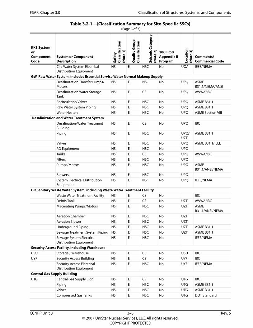
Table 3.2-1—{Classification Summary for Site-Specific SSCs} (Page 3 of 7)
KKS System or Component Code
System or Component Description Sa
fety
Clas
sific
atio
n(N
ote
1)
Qua
lity
Gro
upCl
assi
ficat
ion
Seis
mic
Cat
egor
y(N
ote
2) 10CFR50 Appendix B Program Lo
cati
on(N
ote
3)
Comments/ Commercial Code
CCNPP Unit 3 3–8 Rev. 5© 2007 UniStar Nuclear Services, LLC. All rights reserved.
COPYRIGHT PROTECTED

FSAR: Chapter 3.0 Classification of Structures, Systems, and Components
Central Gas Supply Electrical Distribution Equipment
NS E NSC No UTG IEEE/NEMA
GK, GKB Potable Water System Piping NS E NSC No ASME B31.1 Valves NS E NSC No ASME B31.1 Tanks NS E CS No AWWA /ASME VIII/IBC Pump/Motors NS E NSC No ASME
B31.1/ANSI/NEMAPotable Water System Electrical Distribution Equipment
NS E NSC No IEEE/NEMA
SGA, SGA1, SGC, SGAO, SGE, SGM Fire Water Supply SystemFire Water Distribution System, including valves and hydrants, Balance of Plant (Not providing Safe Shutdown Earthquake Protection)
NS-AQ D NSC No USG/ UZT/ UPQ/ UST/ UTG
NFPA
Fire Water Distribution System, including valves and hydrants, Balance of Plant (Safe Shutdown Equipment Protection following SSE)
NS-AQ D II-SSE Yes USG/ UZT/ UPB
NFPA/ANSI/ASME B31.1
Fire Protection Distribution System including valves and hydrants Seismic Category I Structures (Not Providing Safe Shutdown Equipment Protection following SSE)
NS-AQ D II No NFPA/ANSI/ASME B31.1
Fire Water Storage Tanks and Fire Protection Building
NS-AQ D II-SSE Yes USG/ UZT
NFPA/ANSI/ASME B31.1/IBC
Diesel Engine Driven Pumps and Drivers and subsystems, including diesel fuel oil supply
NS-AQ D II-SSE Yes USG NFPA/ANSI/ASME B31.1
Electric Motor Driven Pump and Driver
NS-AQ D NSC No USG NFPA/ANSI/ASME B31.1
Ventilation Equipment NS-AQ D II-SSE Yes USG NFPA / ASME B31.1 / ASME AG-1
Jockey Pump and driver NS-AQ D NSC No USG NFPA/ANSI/ASME B31.1/NEMA
Fire Protection Makeup Piping and Valves (From Demineralized Water System)
NS-AQ D NSC No UZT NFPA
Fire Suppression SystemsFire Suppression Systems for Site Specific Buildings other than UHS Makeup Water Intake Structure, UHS Electrical Building, and Fire Protection Building
NS-AQ D NSC No NFPA
Table 3.2-1—{Classification Summary for Site-Specific SSCs} (Page 4 of 7)
KKS System or Component Code
System or Component Description Sa
fety
Clas
sific
atio
n(N
ote
1)
Qua
lity
Gro
upCl
assi
ficat
ion
Seis
mic
Cat
egor
y(N
ote
2) 10CFR50 Appendix B Program Lo
cati
on(N
ote
3)
Comments/ Commercial Code
CCNPP Unit 3 3–9 Rev. 5© 2007 UniStar Nuclear Services, LLC. All rights reserved.
COPYRIGHT PROTECTED
FSAR: Chapter 3.0 Classification of Structures, Systems, and Components
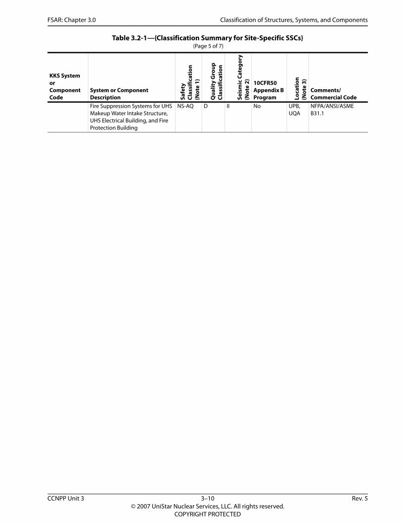
Fire Suppression Systems for UHS Makeup Water Intake Structure, UHS Electrical Building, and Fire Protection Building
NS-AQ D II No UPB, UQA
NFPA/ANSI/ASME B31.1
Table 3.2-1—{Classification Summary for Site-Specific SSCs} (Page 5 of 7)
KKS System or Component Code
System or Component Description Sa
fety
Clas
sific
atio
n(N
ote
1)
Qua
lity
Gro
upCl
assi
ficat
ion
Seis
mic
Cat
egor
y(N
ote
2) 10CFR50 Appendix B Program Lo
cati
on(N
ote
3)
Comments/ Commercial Code
CCNPP Unit 3 3–10 Rev. 5© 2007 UniStar Nuclear Services, LLC. All rights reserved.
COPYRIGHT PROTECTED

FSAR: Chapter 3.0 Classification of Structures, Systems, and Components
Other Site-Specific StructuresSwitchgear Building NS E CS No UBA IBCTurbine Building NS E CS No UMA IBCGrid Systems Control Building NS E CS No UAC IBCElectrical Duct Banks traversing from the Safeguards Buildings to the Four Essential Service Water Buildings and Both Emergency Power Generating Buildings
S C I Yes UJK/ UZT/ UQB/ UBP
IEEE/ACI-349/NEC
Electrical Duct Banks traversing from the Safeguards Buildings to the Switchgear Building
NS E CS No UJK/ UZT/ UBA
IEEE/NEC
Electrical Duct Banks traversing from the Emergency Auxiliary Transformers to the Safeguard Buildings
NS E CS No UBE/ UZT/ UJK
IEEE/NEC
Electrical Duct Banks traversing from the Switchgear Building to the Desalination Plant, Circulating Water Pump Building, Cooling Tower, Switchyard Control House, Site Specific Auxiliary Transformer, Sewage Treatment Plant, and CW Makeup Water Intake Structure
NS E CS No UBA/ UZT/ UPQ/ UQA/ URA/ UAC/ UAA/ UGV/ UPE
IEEE/NEC
Table 3.2-1—{Classification Summary for Site-Specific SSCs} (Page 6 of 7)
KKS System or Component Code
System or Component Description Sa
fety
Clas
sific
atio
n(N
ote
1)
Qua
lity
Gro
upCl
assi
ficat
ion
Seis
mic
Cat
egor
y(N
ote
2) 10CFR50 Appendix B Program Lo
cati
on(N
ote
3)
Comments/ Commercial Code
CCNPP Unit 3 3–11 Rev. 5© 2007 UniStar Nuclear Services, LLC. All rights reserved.
COPYRIGHT PROTECTED

FSAR: Chapter 3.0 Classification of Structures, Systems, and Components
Electrical Duct Banks traversing between miscellaneous buildings
NS E CS No UZT IEEE/NEC
Notes: 1. As defined in U.S. EPR FSAR Section 3.2.1, the US EPR safety classifications, as supplemented by the UniStar Quality
Assurance Program Description (QAPD) classifications, are:S- Safety-related (UniStar QAPD classification - QA Level 1)NS- Non-safety-related (UniStar QAPD classification - QA Level 3)NS-AQ- Supplemented Grade (UniStar QAPD classification - QA Level 2)
2. As defined in Section 3.2.1 and U.S. EPR FSAR Section 3.2.1, the Seismic Classifications are:I – Seismic Category III – Seismic Category IIII-SSE – Seismic Category II Fire Protection structures, systems, and components that are required to remain functional during and following a safe shutdown earthquake to support equipment required to achieve safe shutdown. The following Fire Protection structures, systems, and components are required to remain functional during and after a seismic event: 1) Fire Water Storage Tanks; 2) Fire Protection Building; 3) Diesel driven fire pumps and their associated subsystems and components, including the diesel fuel oil system; 4) Critical support systems for the Fire Protection Building, i.e., ventilation; and 5) The portions of the fire water piping system and components (including isolation valves) which supply water to the stand pipes in buildings that house the equipment required for safe shutdown of the plant following an SSE. Manual actions may be required to isolate the portion of the Fire Protection piping system that is not qualified as Seismic Category II-SSE.
3. Locations are defined below:
Table 3.2-1—{Classification Summary for Site-Specific SSCs} (Page 7 of 7)
KKS System or Component Code
System or Component Description Sa
fety
Clas
sific
atio
n(N
ote
1)
Qua
lity
Gro
upCl
assi
ficat
ion
Seis
mic
Cat
egor
y(N
ote
2) 10CFR50 Appendix B Program Lo
cati
on(N
ote
3)
Comments/ Commercial Code
KKS Designator LocationUAA SwitchyardUAC Grid System Control HouseUBA Switchgear BuildingUBE Auxiliary Power TransformersUBP Emergency Power Generating BuildingUGV Sewage Treatment Plant BuildingUJK Safeguard Buildings ElectricalUMA Turbine BuildingUPB UHS Makeup Water Intake StructureUPE Circulating Water Makeup Intake StructureUQB Essential Service Water Pump BuildingUQA Circulating Water Pump BuildingURA Cooling Tower StructureUSG Fire Water Storage Tanks and Fire Protection
BuildingUST Workshop & Warehouse BuildingUSU Storage / WarehouseUTG Central Gas Supply BuildingUYF Security Access BuildingUZT Outdoor Area
CCNPP Unit 3 3–12 Rev. 5© 2007 UniStar Nuclear Services, LLC. All rights reserved.
COPYRIGHT PROTECTED
FSAR: Chapter 3.0 Wind and Tornado Loadings
3.3 WIND AND TORNADO LOADINGS
This section of the U.S. EPR FSAR is incorporated by reference, with the supplements described in the following sections.
The U.S. EPR FSAR includes the following COL Item in Section 3.3:
A COL applicant that references the U.S. EPR design certification will determine site-specific wind and tornado design parameters and compare these to the standard plant criteria. If the site-specific wind and tornado parameters are not bounded, then the COL applicant will evaluate the design for site-specific wind and tornado events and demonstrate that these loadings will not adversely affect the ability of safety-related structures to perform their safety functions during or after such events.
This COL Item is addressed as follows:
Table 2.0-1 provides a comparison of the wind and tornado parameters for the U.S. EPR FSAR design and the site-specific values.
{The U.S. EPR FSAR design wind and tornado parameters bound the site-specific wind and tornado parameters. Additional discussion regarding the derivation of the site-specific wind and tornado parameters is provided in Section 2.3.1. Seismic Category I structures are designed to withstand the effects of wind and tornado loadings. Wind and tornado parameters in U.S. EPR FSAR Table 2.1-1 are used for design of Seismic Category I structures for CCNPP Unit 3.}
3.3.1 WIND LOADINGS
The U.S. EPR FSAR includes the following COL Item in Section 3.3.1:
A COL applicant that references the U.S. EPR design certification will demonstrate that failure of site-specific structures or components not included in the U.S. EPR standard plant design, and not designed for wind loads, will not affect the ability of other structures to perform their intended safety functions.
This COL Item is addressed as follows:
A discussion of site-specific structures not designed for wind or tornado loadings is provided in Section 3.3.2.3.
3.3.1.1 Design Wind Velocity
{No departures or supplements.}
3.3.1.2 Determination of Applied Wind Forces
{No departures or supplements.}
3.3.1.2.1 Note on Values Used
No departures or supplements.
3.3.2 TORNADO LOADINGS
The U.S. EPR FSAR includes the following COL Item in Section 3.3.2:
CCNPP Unit 3 3–13 Rev. 5© 2007 UniStar Nuclear Services, LLC. All rights reserved.
COPYRIGHT PROTECTED

FSAR: Chapter 3.0 Wind and Tornado Loadings
A COL applicant that references the U.S. EPR design certification will demonstrate that failure of site-specific structures or components not included in the U.S. EPR standard plant design, and not designed for tornado loads, will not affect the ability of other structures to perform their intended safety functions.
This COL Item is addressed as follows:
A discussion of site-specific structures not designed for wind or tornado loadings is provided in Section 3.3.2.3.
3.3.2.1 Applicable Tornado Design Parameters
{No departures or supplements.}
3.3.2.2 Determination of Tornado Forces on Structures
No departures or supplements.
3.3.2.3 Effect of Failure of Structures or Components Not Designed for Tornado Loads
{Non-safety-related structures located on the site and not included in U.S. EPR FSAR Section 3.3.2.3 include:
Fire Protection Water Tanks
Fire Protection Building
Storage / Warehouse
Central Gas Supply Building
Security Access Facility
Switchgear Building
Grid Systems Control Building
Circulating Water System Cooling Tower
Circulating Water System Pump Building
Circulating Water System Makeup Water Intake Structure
Circulating Water System Retention Basin
Desalinization/Water Treatment Plant
Waste Water Treatment Plant
These non-safety-related structures are miscellaneous steel and concrete structures, which are not designed for high wind and tornado loadings. However, the Fire Water Storage Tanks and the Fire Protection Building are designated as Seismic Category II-SSE structures, and are designed to remain functional during and following a design basis seismic event. These structures are not located adjacent to safety-related structures. Thus, their collapse from high
CCNPP Unit 3 3–14 Rev. 5© 2007 UniStar Nuclear Services, LLC. All rights reserved.
COPYRIGHT PROTECTED
FSAR: Chapter 3.0 Wind and Tornado Loadings
winds or tornado loadings would not result in an impact interaction with any safety-related structure. Missiles generated by the collapse of these structures during high wind or tornado loadings are enveloped by the design basis tornado missile loads described in U.S. EPR FSAR Section 3.5.1.4.}
3.3.3 REFERENCES
{No departures or supplements.}
CCNPP Unit 3 3–15 Rev. 5© 2007 UniStar Nuclear Services, LLC. All rights reserved.
COPYRIGHT PROTECTED
FSAR: Chapter 3.0 Water Level (Flood) Design
3.4 WATER LEVEL (FLOOD) DESIGN
This section of the U.S. EPR FSAR is incorporated by reference with the departures and supplements as described in the following sections.
Seismic Category I structures, systems and components (SSCs) can withstand the effects of flooding due to natural phenomena or onsite equipment failures without losing the capability to perform their safety-related functions. The maximum flood and ground water elevations for the U.S. EPR are shown in U.S. EPR FSAR Table 2.1-1 and Table 2.0-1.
{The U.S. EPR FSAR flood and ground water design elevations bound the Calvert Cliffs site-specific elevations or otherwise calculations have been performed to demonstrate that these loadings will not adversely affect the ability of safety-related structures to perform their safety functions during or after such events.}
3.4.1 INTERNAL FLOOD PROTECTION
No departures or supplements.
3.4.2 EXTERNAL FLOOD PROTECTION
{This section of the U.S. EPR FSAR is incorporated by reference with the departures described below:
The U.S. EPR design requires ground water to be at least 3.3 ft (1 m) below grade. The ground water level at the CCNPP Unit 3 site ranges between 4.0 ft (1.2 m) and 10.0 ft (3 m) below proposed grade at all safety-related structures, with the exception of the Essential Service Water Cooling Tower 1 and the Emergency Power Generating Buildings 1 and 2.
While the water table averages approximately 4.0 ft (1.2) below grade at the Essential Service Water Cooling Tower 1, the ground water under some areas of this structure is less than 3.3 feet (1 m) below grade. This does not comply with the U.S. EPR design ground water level of 3.3 feet (1 m) below grade. A calculation demonstrated that the Essential Service Water Cooling Tower 1 can still perform its safety-related function with the ground water at this elevation. The results of the calculation are discussed in Section 3.8.5.5.3.
The Emergency Power Generating Buildings 1 and 2 are located approximately 3.0 ft (0.9 m) above ground water level. This does not comply with the U.S. EPR design ground water level of 3.3 ft (1 m) below grade. A calculation demonstrated that Emergency Power Generating Buildings 1 and 2 can still perform their safety-related functions with the ground water at this elevation. The results of the calculation are discussed in Section 3.8.5.5.2.
U.S. EPR FSAR Section 3.8.5.4 describes the methods and procedures used to evaluate static and dynamic effects of ground water on structures.
The following information supplements the U. S. EPR FSAR:
The U.S. EPR FSAR requires the Probable Maximum Flood (PMF) elevation to be 1 ft (0.3 m) below finished yard grade. This requirement envelopes the CCNPP Unit 3 maximum flood level for all safety-related structures, except the Ultimate Heat Sink (UHS) Makeup Water Intake Structure and the UHS Electrical Building. The UHS Makeup Water Intake Structure and the UHS Electrical Building are located at the shoreline. Since the UHS Makeup Water Intake Structure
CCNPP Unit 3 3–16 Rev. 5© 2007 UniStar Nuclear Services, LLC. All rights reserved.
COPYRIGHT PROTECTED

FSAR: Chapter 3.0 Water Level (Flood) Design
and the UHS Electrical Building are classified as safety-related buildings, they will be designed to meet the requirements of Regulatory Guide 1.27 (NRC, 1976). The UHS Makeup Water Intake Structure and the UHS Electrical Building are designed to be watertight to prevent internal flooding of the buildings. The UHS Makeup Water Intake Structure and the UHS Electrical Building are discussed in Section 2.4.10, Section 3.4.3.10, Section 3.8.5 and Section 9.2.5.}
3.4.3 ANALYSIS OF FLOODING EVENTS
3.4.3.1 Internal Flooding Events
{No departures or supplements.}
3.4.3.2 External Flooding Events
The U.S. EPR FSAR includes the following COL Item in Section 3.4.3.2:
A COL applicant that references the U.S. EPR design certification will confirm the potential site-specific external flooding events are bounded by the U.S. EPR design basis flood values or otherwise demonstrate that the design is acceptable.
This COL Item is addressed as follows:
{U.S. EPR FSAR Section 3.4.3.2 states: “The Seismic Category I structures are not designed for dynamic effects associated with external flooding (e.g., wind, waves, currents) because the design basis flood level is below the finished yard grade.” The design of the CCNPP Unit 3 safety-related structures is consistent with this statement, except the UHS Makeup Water Intake Structure and the UHS Electrical Building. Flooding of these structures is addressed in Section 3.4.3.10.}
3.4.3.3 Reactor Building Flooding Analysis
No departures or supplements.
3.4.3.4 Safeguard Buildings Flooding Analysis
No departures or supplements.
3.4.3.5 Fuel Building Flooding Analysis
No departures or supplements.
3.4.3.6 Nuclear Auxiliary Building Flooding Analysis
No departures or supplements.
3.4.3.7 Radioactive Waste Building Flooding Analysis
No departures or supplements.
3.4.3.8 Emergency Power Generating Buildings Flooding Analysis
No departures or supplements.
3.4.3.9 Essential Service Water Pump Buildings and Essential Service Water Cooling Tower Structures Flooding Analysis
No departures or supplements.
CCNPP Unit 3 3–17 Rev. 5© 2007 UniStar Nuclear Services, LLC. All rights reserved.
COPYRIGHT PROTECTED

FSAR: Chapter 3.0 Water Level (Flood) Design
3.4.3.10 Ultimate Heat Sink Makeup Water Intake Structure Flooding Analysis
The U.S. EPR FSAR includes the following COL Item in Section 3.4.3.10:
A COL applicant that references the U.S. EPR design certification will perform a flooding analysis for the ultimate heat sink makeup water intake structure based on the site-specific design of the structure and the flood protection concepts provided herein.
This COL Item is addressed as follows:
{The maximum flood level at the UHS Makeup Water Intake Structure and UHS Electrical Building location is elevation 39.4 ft (12.0 m) as a result of the surge, wave heights, and wave run-up associated with the PMH as discussed in Section 2.4.5. The UHS Makeup Water Intake Structure and the UHS Electrical Building would experience flooding during a PMH. These structures are designed to withstand the static and dynamic flooding forces, and the UHS Makeup Water pump room areas and electrical rooms are designed to be watertight. The flood protection measures for the UHS Makeup Water Intake Structure and UHS Electrical Building are described in Section 2.4.10.
In the event of flooding due to equipment or piping failure within a UHS Makeup Water pump room, the affected division of the UHS Makeup Water System is assumed to be lost. The flood protection measures for the UHS Makeup Water Intake Structure and UHS Electrical Building ensure that a flood in one division will not impact another division. Thus, there would be two divisions of the UHS Makeup Water System available for fulfillment of the safety function, if one division is assumed to be unavailable due to maintenance.}
3.4.3.11 Permanent Dewatering System
The U.S. EPR FSAR includes the following COL Item in Section 3.4.3.11:
A COL applicant that references the U.S. EPR design certification will define the need for a site-specific permanent dewatering system.
This COL Item is addressed as follows:
{As described in Section 2.4.12.5, based on ground water modelling of post-construction water table elevations, a permanent ground water dewatering system is not anticipated to be a design feature for the CCNPP Unit 3 facility.}
3.4.4 ANALYSIS PROCEDURES
No departures or supplements.
3.4.5 REFERENCES
{NRC, 1976. Ultimate Heat Sink for Nuclear Power Plants, Regulatory Guide 1.27, Revision 2, U.S. Nuclear Regulatory Commission, January, 1976.}
CCNPP Unit 3 3–18 Rev. 5© 2007 UniStar Nuclear Services, LLC. All rights reserved.
COPYRIGHT PROTECTED

FSAR: Chapter 3.0 Missile Protection
3.5 MISSILE PROTECTION
This section of the U.S. EPR FSAR is incorporated by reference with the supplements as described in the following sections.
3.5.1 MISSILE SELECTION AND DESCRIPTION
No departures or supplements.
3.5.1.1 Internally Generated Missiles Outside Containment
No departures or supplements.
3.5.1.2 Internally Generated Missiles Inside Containment
No departures or supplements.
3.5.1.2.1 Credible Internally Generated Missile Sources Inside Containment
No departures or supplements.
3.5.1.2.2 Non-Credible Internally Generated Missile Sources Inside Containment
No departures or supplements.
3.5.1.2.3 Missile Prevention and Protection Inside Containment
The U.S. EPR FSAR includes the following COL Item in Section 3.5.1.2.3:
A COL applicant that references the U.S. EPR design certification will describe controls to confirm that unsecured maintenance equipment, including that required for maintenance and that are undergoing maintenance, will be removed from containment prior to operation, moved to a location where it is not a potential hazard to SSCs important to safety, or seismically restrained to prevent it from becoming a missile.
This COL Item is addressed as follows:
{Calvert Cliffs 3 Nuclear Project, LLC Constellation Generation Group and UniStar Nuclear Operating Services, LLC} shall establish plant procedural controls to ensure that unsecured maintenance equipment, including that required for maintenance and that are undergoing maintenance, will be removed from containment prior to operation, moved to a location where it is not a potential hazard to SSCs important to safety, or restrained to prevent it from becoming a missile.
3.5.1.3 Turbine Missiles
The U.S. EPR FSAR includes the following COL Item in Section 3.5.1.3:
A COL applicant that references the U.S. EPR design certification will confirm the evaluation of the probability of turbine missile generation for the selected turbine generator, P1, is less than 1E-4 for turbine generators favorably oriented with respect to containment.
This COL Item is addressed as follows:
The turbine-generator design consists of a HP/IP turbine stage with three LP turbines as described in U.S. EPR FSAR Section 10.2. A turbine missile analysis has been developed for the
CCNPP Unit 3 3–19 Rev. 5© 2007 UniStar Nuclear Services, LLC. All rights reserved.
COPYRIGHT PROTECTED

FSAR: Chapter 3.0 Missile Protection
selected turbine design. The analysis considers stress corrosion cracking (SCC), brittle fracture and destructive overspeed as potential failure mechanisms. The analysis also addresses inspection intervals in regard to the probability of failure. The turbine missile analysis calculates the probability of turbine rotor failure consistent with the guidance in Regulatory Guide 1.115 (NRC, 1977) and in NUREG-0800 Section 3.5.1.3 (NRC, 2007b). The analysis includes charts on missile generation probabilities versus service time for the HP/IP and LP turbine rotors.
The probability of reaching destructive overspeed is largely dictated by the probability of failure of the governing and overspeed protection system. Turbine overspeed protection is described in U.S. EPR FSAR Section 10.2. The steam turbine has two independent valves in series on each steam inlet with failsafe hydraulic actuators. These valves are tripped by the redundant overspeed protection system.
The inspection requirements for the turbine rotors during major overhauls ensure that indications of SCC will be detected. The turbine rotor inspection program is described in U.S. EPR FSAR Section 10.2 and is consistent with the turbine manufacturer’s recommended inspection intervals required to meet the calculated failure probability of the turbine rotor.
The turbine missile analysis demonstrates that the probability of turbine rotor failure resulting in an ejection of the turbine rotor (or internal structure) fragments through the turbine casing, P1, is less than 1E-4 for a favorably oriented turbine with respect to the containment.
The turbine missile analysis is available for review.
The U.S. EPR FSAR also includes the following COL Item in Section 3.5.1.3:
A COL applicant that references the U.S. EPR design certification will assess the effect of potential turbine missiles from turbine generators within other nearby or co-located facilities.
This COL Item is addressed as follows:
{CCNPP Units 1 and 2 FSAR Section 5.3.1.2, indicates that the probability of turbine missile generation P1 for the CCNPP Units 1 and 2 turbines is less than 1E-5 per year, which is below the threshold value of 1E-4 1E-5 described in Regulatory Guide 1.115 (NRC, 1977). CCNPP Units 1 and 2 UFSAR Section 5.3.1.1. The orientation of CCNPP Unit 1 and Unit 2 turbines has been evaluated and the SSCs important to safety of CCNPP Unit 3 are located outside the low trajectory strike zones as described in Regulatory Guide 1.115. Therefore, CCNPP Unit 3 safety-related SSC are adequately protected from potential CCNPP Unit 1 and Unit 2 turbine missiles.}
3.5.1.4 Missiles Generated by Tornadoes and Extreme Winds
The U.S. EPR FSAR includes the following COL Item in Section 3.5.1.4:
A COL applicant that references the U.S. EPR design certification will evaluate the potential for other missiles generated by natural phenomena, such as hurricanes and extreme winds, and their potential impact on the missile protection design features of the U.S. EPR.
This COL Item is addressed as follows:
All Seismic Category I structures that make up the U.S. EPR standard design meet the most stringent Region I tornado intensity requirements of Regulatory Guide 1.76 (NRC, 2007a). The
CCNPP Unit 3 3–20 Rev. 5© 2007 UniStar Nuclear Services, LLC. All rights reserved.
COPYRIGHT PROTECTED

FSAR: Chapter 3.0 Missile Protection
associated tornado wind speeds (230 mph (103 m/s) maximum) represent an exceedance frequency of 1E-07 per year. Region I tornado missile parameters are reflected in U.S. EPR FSAR Table 3.5-1 and are used in the standard design of all Seismic Category I structures.
{The CCNPP Unit 3 site is located off the Chesapeake Bay near Lusby, Maryland. Using Regulatory Guide 1.76, Figure 1, this site lies in tornado intensity Region II. The associated wind speeds (200 mph (89 m/s) maximum) represent an exceedance frequency of 1E-07 per year. The CCNPP Unit 3 site is located in Region II. As such, the Region I wind speed and resulting missile spectrum used for the U.S. EPR standard is conservative with respect to the Regulatory Guide 1.76 acceptance criteria.
Regulatory Guide 1.76 (NRC, 2007a) does not address extreme winds such as hurricane winds or the missiles associated with such winds. Therefore, additional site-specific wind conditions were considered as follows:
Summarizing from Section 2.3.1, the following meteorological data is specific to the CCNPP site and provides a site-specific comparative justification for the use of the tornado design-basis missile spectrum for other potentially extreme high wind conditions:
Annually, Maryland has a relatively low number of tornados compared to much of the contiguous United States. From 1950 to 1995, the annual average number of tornados is four, with an annual average of strong-violent tornados (F2 - F5) of one. Based on National Weather Service meteorological data from January 1, 1950 to December 31, 2006, there were 12 tornados reported in Calvert County with estimated minimum and maximum Fujita damage scales ranging from F0 to F2, respectively. This equates to estimated wind speeds ranging from 73 mph (117 km/hr) to a maximum of 157 mph (253 km/hr).
A review of the National Hurricane Center statistics from 1851 to 2004 found only 2 direct hits on Maryland, with neither classified greater than a category 2 on the Saffir-Simpson scale, representing estimated wind speeds ranging from 74 mph (119 km/hr) to 110 mph (177 km/hr).
In addition, a review of all recorded cases of high winds (winds greater than 58 mph (93 km/hr)) from meteorological data from June 2, 1980 to December 31, 2006 for Calvert County, Maryland, found 17 events with wind speeds ranging from 58 mph (93 km/hr) to 104 mph (167 km/hr).
For a general comparison, the strongest of tornadoes are classified as F4 and F5 in the Fujita damage scale and have estimated winds speeds of 207 mph (333 km/hr) and higher. Likewise, the strongest of hurricanes are those classified as 4 and 5 in the Saffir-Simpson scale with estimated winds speeds of 131 mph (211 km/hr) and higher. By comparison of the site-specific meteorological data, and the estimated strongest wind speed classifications for both tornado and hurricane conditions, it is reasonable to conclude that the Region I tornado missile spectrum from Regulatory Guide 1.76 is a conservative representation of those that could be generated by the less intense extreme wind conditions anticipated at the CCNPP Unit 3 site.}
The U.S. EPR FSAR also includes the following COL Item in Section 3.5.1.4:
For sites with surrounding ground elevations that are higher than plant grade, a COL applicant that references the U.S. EPR design certification will confirm that automobile
CCNPP Unit 3 3–21 Rev. 5© 2007 UniStar Nuclear Services, LLC. All rights reserved.
COPYRIGHT PROTECTED

FSAR: Chapter 3.0 Missile Protection
missiles cannot be generated within a 0.5 miles radius of safety-related SSCs that would lead to impact higher than 30 ft above plant grade.
This COL Item is addressed as follows:
The tornado missile spectrum requirements provided in Regulatory Guide 1.76 (NRC, 2007a) describe three design-basis missiles; a pipe, sphere, and automobile. The pipe and sphere missiles are assumed to impact applicable structures at all elevations. The automobile missile is to be considered at all altitudes less than 30 ft (9.1 m) above all grade levels within 0.5 miles (0.8 km) of the plant structures.
Category I structures within the Nuclear Island (NI) base mat which include the Reactor, Fuel, and Safeguard Buildings (SB) 2 and 3 are protected by being housed in independent hardened structures. Walls and roof slabs of the hardened structures are designed of heavily reinforced concrete that envelopes the Region I tornado missile spectrum requirements. SB 1 and 4 are not enclosed in hardened structures, due to the system redundancy provided by SB 2 and 3. Although SB 1 and 4 are not housed in an independent hardened structure, they are constructed of heavily reinforced concrete and all wall and roof slab sections meet the minimum acceptable tornado missile barrier guidance identified in NUREG-0800, Section 3.5.3 (NRC, 2007b).
Likewise, the U.S. EPR standard design of all Category I structures outside the NI base mat are constructed of reinforced concrete and all wall and roof slabs meet the Region I design-basis missile spectrum, including the automobile missile guidance of Regulatory Guide 1.76 (NRC, 2007a) for all structural elevations. {An exception to the previous statement is that for the Essential Service Water Cooling Tower and pump structures, the automobile missile impact is considered on all wall elements at all elevations, but not the roof slab. The highest elevation within the 0.5 mile (0.8 km) radius at CCNPP Unit 3 is at an approximate elevation of 130 ft (39.6 m). Adding the 30 ft (9.1 m) requirement, all elements below elevation 160 ft (48.8 m) require evaluation of the automobile missile. Normal grade elevation at the Essential Service Water Cooling Tower and pump structures is approximately 82 ft (25 m). Therefore, structural elements less than 78 ft (23.8 m) high require automobile missile evaluation. The height of the Essential Service Water Cooling Tower and pump structures is approximately 96 ft (29 m). Hence, the roof slabs on these structures do not require automobile missile evaluation. On this basis, the site-specific conditions are conservatively enveloped for all required elevations.
Thus, by the standard U.S. EPR meeting the Region I tornado missile spectrum requirements for all Category I structures, the site-specific conditions at CCNPP Unit 3 are in compliance with all Regulatory Guide 1.76 (NRC, 2007a) tornado missile requirements.}
3.5.1.5 Site Proximity Missiles (Except Aircraft)
The U.S. EPR FSAR includes the following COL Item in Section 3.5.1.5:
A COL applicant that references the U.S. EPR design certification will evaluate the potential for site proximity explosions and missiles generated by these explosions for their potential impact on missile protection design features.
This COL Item is addressed as follows:
In accordance with Regulatory Guide 1.206 (NRC, 2007c), the following missile sources have been considered and are discussed in Section 2.2:
CCNPP Unit 3 3–22 Rev. 5© 2007 UniStar Nuclear Services, LLC. All rights reserved.
COPYRIGHT PROTECTED
FSAR: Chapter 3.0 Missile Protection
Train explosions
Truck explosions
Ship or barge explosions
Industrial facilities
Pipeline explosions
Military facilities
Section 2.2 evaluates the effects of potential accidents in the vicinity of the site from present and projected industrial, transportation, and military facilities and operations. Each transportation mode and facility was evaluated with regard to the effects from potential accidents relating to explosions, flammable vapor clouds (delayed ignition), and toxic chemicals (vapors or gases), including liquid spills. Evaluation acceptance criteria for these hazards are in accordance with Regulatory Guides 1.91 and 1.78 (NRC, 1978a and NRC, 2001, respectively).
{From Section 2.2 and 3.5.1.3 (turbine missile generation of CCNPP Units 1 and 2), none of the potential site-specific external event hazards evaluated (except aircraft hazards which are discussed below) resulted in an unacceptable affecteffect important to the safe operation of CCNPP Unit 3. This conclusion is substantiated by each potential external hazard being screened based on applicable regulatory guidance or the hazard contribution to core damage frequency (CDF) was deemed to be less than 1E-6 per yeareither being screened based on: 1) applicable regulatory guidance; or 2) the hazard contribution to core damage frequency (CDF) being less than 1E-6 per year.}
3.5.1.6 Aircraft Hazards
The U.S. EPR FSAR includes the following COL Item in Section 3.5.1.6:
A COL applicant that references the U.S. EPR design certification will evaluate site-specific aircraft hazards and their potential impact on plant SSCs.
This COL Item is addressed as follows:
In accordance with Regulatory Guide 1.70 (NRC, 1978b), Regulatory Guide 1.206 (NRC, 2007c), and NUREG-0800, Section 3.5.1.6 (NRC, 2007b), the risks due to aircraft hazards should be sufficiently low. Furthermore, aircraft accidents that could lead to radiological consequences in excess of the exposure guidelines of 10 CFR 50.34(a)(1) (CFR, 2008) with a probability of occurrence greater than an order of magnitude of 1E-7 per year should be considered in the design of the plant.
Section 2.2 describes the site-specific aircraft and airway hazard evaluations. {Due to the number of annual aircraft operations at two airports and close proximity of airways V31 and V93, a probabilistic risk assessment (PRA) was performed to assess the core damage frequency (CDF) effect from these hazards. Results of the PRA state the total CDF from the site airplane crash scenarios was calculated to be 1.5E-07 per year; and the resulting containment release frequency was calculated to be approximately 3E-08 per year. Therefore, the aircraft hazard meets the NUREG-0800 Section 3.5.1.6 acceptance criteria (refer to Section 19.1.5.4.4).
CCNPP Unit 3 3–23 Rev. 5© 2007 UniStar Nuclear Services, LLC. All rights reserved.
COPYRIGHT PROTECTED

FSAR: Chapter 3.0 Missile Protection
Thus, by compliance with the NUREG-0800 acceptance criteria, no additional design-basis criteria for the standard U.S EPR design is required as a result of the site-specific aircraft hazard for CCNPP Unit 3.}
3.5.2 STRUCTURES, SYSTEMS, AND COMPONENTS TO BE PROTECTED FROM EXTERNALLY GENERATED MISSILES
No departures or supplements.
3.5.3 BARRIER DESIGN PROCEDURES
No departures or supplements.
3.5.4 REFERENCES
{CFR, 2008. Contents of Construction Permit and Operating License Applications; Technical Information, Title 10, Code of Federal Regulations, Part 50.34, U.S. Nuclear Regulatory Commission, February 2008.
NRC, 1977. Protection Against Low-Trajectory Turbine Missiles, Regulatory Guide 1.115, Revision 1, U.S. Nuclear Regulatory Commission, July 1977.
NRC, 1978a. Evaluations of Explosions Postulated to Occur on Transportation Routes Near Nuclear Power Plants, Regulatory Guide 1.91, Revision 1, U.S. Nuclear Regulatory Commission, February 1978.
NRC, 1978b. Standard Format and Content of Safety Analysis Reports for Nuclear Power Plants (LWR Edition), Regulatory Guide 1.70, Revision 3, U.S. Nuclear Regulatory Commission, November 1978.
NRC, 2001. Evaluating the Habitability of a Nuclear Power Plant Control Room During a Postulated Hazardous Chemical Release, Regulatory Guide 1.78, Revision 1, U.S. Nuclear Regulatory Commission, December 2001.
NRC, 2007a. Design-Basis Tornado and Tornado Missiles for Nuclear Power Plants, Regulatory Guide 1.76, Revision 1, U.S. Nuclear Regulatory Commission, March 2007.
NRC, 2007b. Standard Review Plan (SRP) for the Review of Safety Analysis Reports for Nuclear Power Plants, NUREG-0800, U.S. Nuclear Regulatory Commission, March 2007.
NRC, 2007c. Combined License Applications for Nuclear Power Plants (LWR Edition), Regulatory Guide 1.206, Revision 0, U.S. Nuclear Regulatory Commission, June 2007.}
CCNPP Unit 3 3–24 Rev. 5© 2007 UniStar Nuclear Services, LLC. All rights reserved.
COPYRIGHT PROTECTED

FSAR: Chapter 3.0 Protection Against Dynamic Effects Associated with Postulated Rupture of Piping
3.6 PROTECTION AGAINST DYNAMIC EFFECTS ASSOCIATED WITH POSTULATED RUPTURE OF PIPING
This section of the U.S. EPR FSAR is incorporated by reference with the supplements as described in the following sections.
3.6.1 PLANT DESIGN FOR PROTECTION AGAINST POSTULATED PIPING FAILURES IN FLUID SYSTEMS OUTSIDE OF CONTAINMENT
The U.S. EPR FSAR includes the following COL Holder Item in Section 3.6.1:
A COL applicant that references the U.S. EPR design certification will perform the pipe break hazards analysis and reconcile deviations in the as-built configuration to this analysis.
This COL Holder Item is addressed as follows:
{Constellation Generation Group Calvert Cliffs 3 Nuclear Project, LLC and UniStar Nuclear Operating Services, LLC} shall perform a pipe break hazard analysis as part of the piping design. It is used to identify postulated break locations and layout changes, support design, whip restraint design, and jet shield design. The final design for these activities shall be completed prior to fabrication and installation of the piping and connected components. The as-built reconciliation of the pipe break hazards analysis shall be completed prior to fuel load.
3.6.2 DETERMINATION OF RUPTURE LOCATIONS AND DYNAMIC EFFECTS ASSOCIATED WITH THE POSTULATED RUPTURE OF PIPING
No departures or supplements.
3.6.2.1 Criteria Used to Define Break and Crack Location and Configuration
The U.S. EPR FSAR includes the following COL Holder Item in Section 3.6.2.1:
A COL applicant that references the U.S. EPR design certification will perform the pipe break hazards analysis and reconcile deviations in the as-built configuration to this analysis.
This COL Holder Item is addressed as follows:
{Constellation Generation Group Calvert Cliffs 3 Nuclear Project, LLC and UniStar Nuclear Operating Services, LLC} shall perform a pipe break hazard analysis as part of the piping design. It is used to identify postulated break locations and layout changes, support design, whip restraint design, and jet shield design. The final design for these activities shall be completed prior to fabrication and installation of the piping and connected components. The as-built reconciliation of the pipe break hazards analysis shall be completed prior to fuel load.
3.6.2.2 Guard Pipe Assembly Design Criteria
No departures or supplements.
3.6.2.3 Analytical Methods to Define Forcing Functions and Response Models
No departures or supplements.
3.6.2.4 Dynamic Analysis Methods to Verify Integrity and Operability
No departures or supplements.
CCNPP Unit 3 3–25 Rev. 5© 2007 UniStar Nuclear Services, LLC. All rights reserved.
COPYRIGHT PROTECTED

FSAR: Chapter 3.0 Protection Against Dynamic Effects Associated with Postulated Rupture of Piping
3.6.2.5 Implementation of Criteria Dealing with Special Features
3.6.2.5.1 Pipe Whip Restraints
The U.S. EPR FSAR includes the following COL Holder Item in Section 3.6.2.5.1:
A COL applicant that references the U.S. design certification will provide diagrams showing the final as-designed configurations, locations, and orientations of the pipe whip restraints in relation to break locations in each piping system.
This COL Holder Item is addressed as follows:
{Constellation Generation Group Calvert Cliffs 3 Nuclear Project, LLC and UniStar Nuclear Operating Services, LLC} shall provide the diagrams showing the final as-designed configurations, locations, and orientations of the pipe whip restraints in relation to break locations in each piping system prior to fabrication and installation of the piping system.
3.6.2.5.2 Structural Barrier Design
No departures or supplements.
3.6.2.5.3 Evaluation of Pipe Rupture Environmental Effects
No departures or supplements.
3.6.2.6 References
No departures or supplements.
3.6.3 LEAK-BEFORE-BREAK EVALUATION PROCEDURES
The U.S. EPR FSAR includes the following COL Holder Item in Section 3.6.3:
A COL applicant that references the U.S. EPR design certification will confirm that the design LBB analysis remains bounding for each piping system and provide a summary of the results of the actual as-built, plant-specific LBB analysis, including material properties of piping and welds, stress analyses, leakage detection capability, and degradation mechanisms.
This COL Holder Item is addressed as follows:
{Constellation Generation Group Calvert Cliffs 3 Nuclear Project, LLC and UniStar Nuclear Operating Services, LLC} shall confirm that the design Leak-Before-Break (LBB) analysis remains bounding for each applicable as-built piping system. A summary of the results of the actual as-built, plant-specific LBB analysis, including material properties of piping and welds, stress analyses, leakage detection capability, and degradation mechanisms will be provided prior to fuel load.
CCNPP Unit 3 3–26 Rev. 5© 2007 UniStar Nuclear Services, LLC. All rights reserved.
COPYRIGHT PROTECTED
FSAR: Chapter 3.0 Seismic Design
3.7 SEISMIC DESIGN
This section of the U.S. EPR FSAR is incorporated by reference with the supplements as described in the following sections.
3.7.1 SEISMIC DESIGN PARAMETERS
{Section 3.7.1 describes the reconciliation of the site-specific seismic parameters for CCNPP Unit 3 and demonstrates that these parameters are enveloped by the Certified Seismic Design Response Spectra (CSDRS) (anchored at 0.3 g Peak Ground Acceleration (PGA)) and the 10 generic soil profiles used in the U.S. EPR FSAR.
3.7.1.1 Design Ground Motion
The Ground Motion Response Spectra (GMRS) for CCNPP Unit 3, which were developed using Regulatory Guide 1.165 (NRC, 1997) and Regulatory Guide 1.208 (NRC, 2007a) are bounded by the CSDRS at all frequencies, including the high frequency region of the ground response spectra. Therefore, the CSDRS used in the design of the U.S. EPR are applicable to CCNPP Unit 3.
The site-specific Seismic Category I structures at CCNPP Unit 3 are the:
Ultimate Heat Sink (UHS) Makeup Water Intake Structure
UHS Electrical Building
Buried Electrical Duct Banks and Pipes
The Seismic Category I UHS Makeup Water Intake Structure and UHS Electrical Building are situated adjacent to an intake channel at the CCNPP Unit 3 site along the west bank of the Chesapeake Bay. Figures 9.2-4, 9.2-5 and 9.2-6 provide plan views of the UHS Makeup Water Intake Structure and UHS Electrical Building, along with associated sections. The bottom of the UHS Makeup Water Intake Structure base mat is situated approximately 25 ft (8 m) below sea level National Geodetic Vertical Datum of 1929 (NGVD 29)37 ft (11.3 m) below a nominal grade elevation of 10 ft (3.3 m), while the bottom of the UHS Electrical Building mat foundation is situated approximately 20 ft (6 m) below grade and 10 ft (3 m) below sea level (NGVD 29). The layout of the Seismic Category I buried electrical duct banks and Seismic Category I buried piping is defined in Figures 3.8-1 and 3.8-2, and Figures 3.8-3 and 3.8-4, respectively.
3.7.1.1.1 Design Ground Motion Response Spectra
Seismic Reconciliation of CSDRS and GMRS for the Nuclear Island Common Base MmatThe GMRS for the horizontal direction in the free-field at the foundation level of the NI Common base mat structure has a peak ground acceleration of 0.067 g. Appendix S of 10 CFR Part 50 (CFR, 2008) requires that the horizontal component of the SSE ground motion in the free-field at the foundation level of the structures must be an appropriate response spectrum with a peak ground acceleration of at least 0.1 g. A comparison of the GMRS versus the 0.1 g European Utility Requirements (EUR)-based CSDRS curves is shown in Figure 3.7-3, and Figure 3.7-4, and it shows that the GMRS is enveloped by the 0.1 g CSDRS curves except for the very low frequency range. The minimum horizontal SSE ground motion is defined as the envelope of the GMRS and the set of CSDRS curves anchored at 0.1 g peak ground acceleration.
The vertical SSE spectrum is defined as the vertical GMRS.The SSE for CCNPP Unit 3 is defined as the lowest design spectrum used for the design of Seismic Category I structures. Therefore, the
CCNPP Unit 3 3–27 Rev. 5© 2007 UniStar Nuclear Services, LLC. All rights reserved.
COPYRIGHT PROTECTED
FSAR: Chapter 3.0 Seismic Design
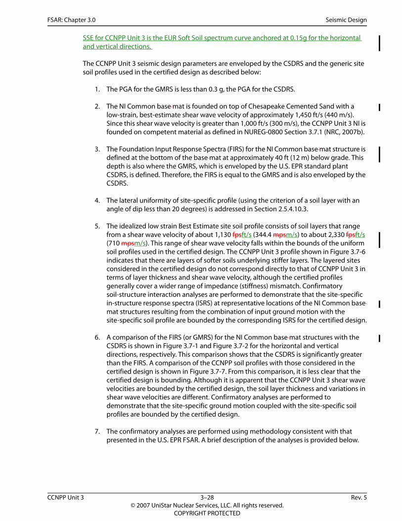
SSE for CCNPP Unit 3 is the EUR Soft Soil spectrum curve anchored at 0.15g for the horizontal and vertical directions.
The CCNPP Unit 3 seismic design parameters are enveloped by the CSDRS and the generic site soil profiles used in the certified design as described below:
1. The PGA for the GMRS is less than 0.3 g, the PGA for the CSDRS.
2. The NI Common base mat is founded on top of Chesapeake Cemented Sand with a low-strain, best-estimate shear wave velocity of approximately 1,450 ft/s (440 m/s). Since this shear wave velocity is greater than 1,000 ft/s (300 m/s), the CCNPP Unit 3 NI is founded on competent material as defined in NUREG-0800 Section 3.7.1 (NRC, 2007b).
3. The Foundation Input Response Spectra (FIRS) for the NI Common base mat structure is defined at the bottom of the base mat at approximately 40 ft (12 m) below grade. This depth is also where the GMRS, which is enveloped by the U.S. EPR standard plant CSDRS, is defined. Therefore, the FIRS is equal to the GMRS and is also enveloped by the CSDRS.
4. The lateral uniformity of site-specific profile (using the criterion of a soil layer with an angle of dip less than 20 degrees) is addressed in Section 2.5.4.10.3.
5. The idealized low strain Best Estimate site soil profile consists of soil layers that range from a shear wave velocity of about 1,130 fpsft/s (344.4 mpsm/s) to about 2,330 fpsft/s (710 mpsm/s). This range of shear wave velocity falls within the bounds of the uniform soil profiles used in the certified design. The CCNPP Unit 3 profile shown in Figure 3.7-6 indicates that there are layers of softer soils underlying stiffer layers. The layered sites considered in the certified design do not correspond directly to that of CCNPP Unit 3 in terms of layer thickness and shear wave velocity, although the certified profiles generally cover a wider range of impedance (stiffness) mismatch. Confirmatory soil-structure interaction analyses are performed to demonstrate that the site-specific in-structure response spectra (ISRS) at representative locations of the NI Common base mat structures resulting from the combination of input ground motion with the site-specific soil profile are bounded by the corresponding ISRS for the certified design.
6. A comparison of the FIRS (or GMRS) for the NI Common base mat structures with the CSDRS is shown in Figure 3.7-1 and Figure 3.7-2 for the horizontal and vertical directions, respectively. This comparison shows that the CSDRS is significantly greater than the FIRS. A comparison of the CCNPP soil profiles with those considered in the certified design is shown in Figure 3.7-7. From this comparison, it is less clear that the certified design is bounding. Although it is apparent that the CCNPP Unit 3 shear wave velocities are bounded by the certified design, the soil layer thickness and variations in shear wave velocities are different. Confirmatory analyses are performed to demonstrate that the site-specific ground motion coupled with the site-specific soil profiles are bounded by the certified design.
7. The confirmatory analyses are performed using methodology consistent with that presented in the U.S. EPR FSAR. A brief description of the analyses is provided below.
CCNPP Unit 3 3–28 Rev. 5© 2007 UniStar Nuclear Services, LLC. All rights reserved.
COPYRIGHT PROTECTED

FSAR: Chapter 3.0 Seismic Design
Confirmatory Analyses
Soil ProfilesTable 3.7-1 shows the low-strain Best Estimate (BE) soil profile that was used in the site-specific Soil Structure Interaction (SSI) analysis.
Estimates for the low-strain Upper Bound (UB) and Lower Bound (LB) case soil properties for the SSI analysis were obtained by varying the soil shear modulus, GBE of the low-strain BE case. The damping and Poisson’s ratio remain unchanged from the BE values. The estimates for the low-strain shear modulus, GUB, for the UB soil case are obtained by multiplying GBE by (1+Cv), where Cv is a factor that accounts for uncertainties in SSI analysis and soil properties. The value of Cv is conservatively assumed as 1.0. The estimates for the low-strain shear modulus, GLB, are obtained by dividing GBE by (1+Cv). The estimates for the low-strain shear moduli of LB and UB soil cases are 0.5*GBE and 2.0*GBE, respectively.
Table 3.7-2 and Table 3.7-3 show the estimated soil profiles for the low-strain LB and UB soil cases used in the site-specific SSI analysis.
Minimum Ground MotionIn accordance with Appendix S of 10 CFR Part 50, Tthe minimum horizontal SSE ground motions for CCNPP Unit 3 areis the envelope of the horizontal GMRS and the 0.1 g EUR-based CSDRS. for the horizontal directions and The minimum vertical SSE ground motion is defined as the vertical GMRS for the vertical direction. The cConfirmatory SSI analyses use the EUR Soft Soil input motion anchored at 0.1 g PGA for horizontal as well as vertical directions. The EUR Soft Soil input motion is selected because the low-strain best estimate CCNPP Unit 3 soil profile has a shear wave velocity range of approximately 1,100 fpsft/s (335 mpsm/s) to 2,330 fpsft/s (710 mpsm/s) and is considered a soft soil. It is observed that although the EUR Soft Soil Spectrum at 0.1 g PGA is exceeded by the minimum horizontal SSE ground motion for frequencies less than 0.7 Hz, the exceedance occurs outside the frequency range of interest for the SSI analysis. It is also noted that the U.S. EPR FSAR EUR Soft Soil spectrum (at 0.3 g PGA) completely envelops the CCNPP Unit 3 SSE ground motion in both horizontal and vertical directions, so the certified design bounds the exceedances noted above for the 0.1 g SSE spectra.
The use of the 0.1 g spectrum in the vertical direction is conservative (as it far exceeds the demand for the vertical GMRS in the frequency range of interest for the SSI analysis as shown in Figure 3.7-5) and chosen as a matter of convenience as the time histories are readily available.
SSI AnalysisThe same SSI model and methodology used for the U.S. EPR FSAR is used for the confirmatory analyses, except that OBE structural damping is used since it is unlikely that the 0.1 g PGA motion will result in high enough stress levels to justify SSE damping levels.
SSI analyses for three soil cases, namely CCNPP Unit 3 low-strain BE, CCNPP Unit 3 low-strain LB and CCNPP Unit 3 low-strain UB, were performed using EUR Soft Soil motion with 0.1 g PGA as seismic input.
Response spectra for 5 percent damping in the three directions are generated at the following critical locations:
Reactor Building Internal Structure at Elev. 16.9 ft (5.15 m) and 64.0 ft (19.5 m).
CCNPP Unit 3 3–29 Rev. 5© 2007 UniStar Nuclear Services, LLC. All rights reserved.
COPYRIGHT PROTECTED

FSAR: Chapter 3.0 Seismic Design
Safeguard Building 1 at Elev. 27 ft (8.1 m) and 69.9 ft (21.0 m).
Safeguard Building 2/3 at Elev. 27 ft (8.1 m) and 50.5 ft (15.4 m).
Safeguard Building 4 at Elev. 69.9 ft (21.0 m).
Containment Building at Elev. 123 ft (37.6 m) and 190 ft (58.0 m).
A comparison of the 5 percent damped In-Structure Response Spectra (ISRS) for the CCNPP Unit 3 BE, LB and UB soil cases with the corresponding peak-broadened Design Certification ISRS show that the certified design bounds the CCNPP Unit 3 seismic demands by a large margin (Figures 3.7-8 through 3.7-34). Therefore, the CCNPP Unit 3 site-specific seismic parameters are bounded by the U.S. EPR results.
Seismic Reconciliation of CSDRS and GMRS for the EPGBs and ESWBsThe acceptability of the seismic input used in the analysis of the Seismic Category I Emergency Power Generating Buildings (EPGBs) and the Seismic Category I Essential Service Water Buildings (ESWBs), i.e., Essential Service Water Cooling Towers, is established in accordance with the criteria defined in U.S. EPR FSAR Figure 3.7.1-30. This is performed using the comparative spectra plots contained in Figures 3.7-35 and 3.7-36. These plots compare the three EUR spectra that define the horizontal and vertical CSDRS for the U.S. EPR with the horizontal and vertical site-specific FIRS defined at grade. As indicated in U.S. EPR FSAR Section 3.7.1.1.1, the three EUR spectra used to represent the CSDRS are anchored at 0.3 g and define the input at a location 41.33 ft (12.6 m) below grade. Consideration of these three spectra in the comparative plots is appropriate since they were the input for the structure-soil-structure interaction (SSSI) analysis that defined the amplified seismic input for the EPGB and ESWB that is shown in U.S. EPR FSAR Figures 3.7.1-33 and 3.7.1-34. The FIRS depicted in the comparative plots are defined in Table 3.7-4 and represent the ground motions at grade corresponding to the site-specific GMRS, which, as indicated in Section 2.5.2.6, are defined 41 ft (12.5 m) below grade. Use of the FIRS defined at grade in the comparative plots is conservative since they envelop the FIRS corresponding to the bottoms of the base mats for the EPGB and ESWB, which are located 6 ft (1.8 m) and 22 ft (6.7 m) below grade, respectively.
Complete site reconciliation of the seismic input parameters for the EPGB and ESWB is established based on the following:
Horizontal and vertical FIRS being completely enveloped by the EUR soft soil spectrum; and
CCNPP Unit 3 soil is within the site parameters defined for the U.S. EPR, based on compliance with Guidelines 1 through 5 as defined in U.S. EPR FSAR Section 2.5.2.6. Compliance is established in Sections 2.5.2.6, 2.5.4.10.3, and 3.7.1.
Foundation Input Response Spectra for Site-specific StructuresThe geotechnical data currently available in the vicinity for the location of the UHS Makeup Water Intake Structure and UHS Electrical Building is preliminary. Consequently, horizontal and vertical FIRS are conservatively estimated as outlined below.
The design response spectrum used to analyze the UHS Makeup Water Intake Structure is the EUR soft soil spectrum scaled down to a zero period acceleration (ZPA) of 0.15 g. The EUR soft soil spectrum, which is described in U.S. EPR FSAR Section 3.7.1.1.1, is consistent with the
CCNPP Unit 3 3–30 Rev. 5© 2007 UniStar Nuclear Services, LLC. All rights reserved.
COPYRIGHT PROTECTED

FSAR: Chapter 3.0 Seismic Design
preliminary in-situ soil properties defined in the vicinity of the UHS Makeup Water Intake Structure.
Figure 3.7-38 establishes the acceptability of using the scaled down EUR soft soil spectrum as the design response spectra for the UHS Makeup Water Intake Structure. This figure compares the scaled down EUR soft soil spectrum with the following spectra:
Site-specific horizontal GMRS for the NI defined 41 ft (12.5 m) below grade or at elevation 44 ft (13.4 m). This elevation is approximately 70 ft (21.3 m) above the bottom of the base mat elevation of the UHS Makeup Water Intake Structure, i.e., at elevation -25-27 ft (-7.6-8.2 m).
Regulatory Guide 1.60 (NRC, 1973) horizontal spectrum scaled to a ZPA of 0.10 g. This ZPA is the minimum allowable value defined in Appendix S to 10 CFR 50 (CFR, 2008).
Figure 3.7-38 establishes that there is significant margin between the scaled down EUR soft soil spectrum and the two horizontal spectra identified above, except at frequencies significantly below 1 Hz. Significant margins also exist between the EUR soft soil spectrum and both the site-specific vertical GMRS and a vertical spectrum representing the Regulatory Guide 1.60 (NRC, 1973) spectrum scaled to a ZPA of 0.1 g. Upon completion of the final geotechnical site investigation, it will be confirmed that the GMRS is a conservative representation of the FIRS for the UHS Makeup Water Intake Structure.
Structure-to-structure effects exist from the UHS Makeup Water Intake Structure on the UHS Electrical Building. Consequently, the design response spectra for the UHS Electrical Building are conservatively established as envelopes of:
Half the EUR soft soil spectrum (i.e., with a ZPA of 0.15 g).
ISRS (with a ZPA of 0.35 g), developed at the operating deck of the UHS Makeup Water Intake Structure (i.e., Elevation +11.5 ft (+3.51 m) NVGD 29) and in close proximity to grade.
Upon completion of the final geotechnical site investigation, the acceptance of the aforementioned FIRS for the UHS Electrical Building will be confirmed.
Half the EUR soft soil spectrum will be used to analyze the site-specific buried utilities.
3.7.1.1.2 Design Ground Motion Time History
The design ground motion time histories used for the UHS Makeup Water Intake Structure time history analysis are scaled down time histories (ZPA of 0.15 g) based on the soft soil, site-independent time histories developed from the broad banded EUR spectrum from the U.S. EPR NI Design Certification (ZPA of 0.30 g). As discussed in Section 3.7.1.1.1, the EUR soft soil profiles are consistent with the preliminary in-situ soil data at the UHS Makeup Water Intake Structure.
A time history analysis is not performed for the UHS Electrical Building as it is treated as a soil inclusion. Similarly, a time history analysis is not performed for either the site-specific buried utilities or the Fire Protection piping.
CCNPP Unit 3 3–31 Rev. 5© 2007 UniStar Nuclear Services, LLC. All rights reserved.
COPYRIGHT PROTECTED
FSAR: Chapter 3.0 Seismic Design
3.7.1.2 Percentage of Critical Damping Values
No departures or supplements.
3.7.1.3 Supporting Media for Seismic Category I Structures
The supporting media for the seismic analysis is shown in Figure 3.7-6. The variation in shear wave velocity is addressed in a confirmatory soil-structure interaction analysis, demonstrating that the site-specific supporting media are bounded by the analyses for the certified design.
3.7.1.4 References
NRC, 1973. Design Response Spectra for Seismic Design of Nuclear Power Plants, Regulatory Guide 1.60, Revision 1, U.S. Nuclear Regulatory Commission, December 1973.
NRC, 1997. Identification and Characterization of Seismic Sources and Determination of Safe Shutdown Earthquake Ground Motion, Regulatory Guide 1.165, Revision 0, U.S. Nuclear Regulatory Commission, March 1997.
NRC, 2007a. A Performance-Based Approach to Define the Site Specific Earthquake Ground Motion, Regulatory Guide 1.208, Revision 0, U.S. Nuclear Regulatory Commission, March 2007.
NRC, 2007b. Standard Review Plan (SRP) for the Review of Safety Analysis Reports for Nuclear Power Plants, NUREG-0800, U.S. Nuclear Regulatory Commission, March 2007.
CFR, 2008. Domestic Licensing of Production and Utilization Facilities, 10 CFR Part 50, U.S. Nuclear Regulatory Commission, February 2008.}
3.7.2 SEISMIC SYSTEM ANALYSIS
The U.S. EPR FSAR includes the following COL Item in Section 3.7.2:
A COL applicant that references the U.S. EPR design certification will confirm that the site-specific seismic response is within the parameters of Section 3.7 of the U.S. EPR standard design.
This COL Item is addressed as follows:
{As established in Section 3.7.1.1.1, the seismic input to the analysis of the Seismic Category I EPGBs and the Seismic Category I ESWBs is in accordance with the U.S. EPR FSAR seismic criteria. Figures 3.7-35 and 3.7-36 establish that the U.S. EPR FSAR seismic input motion is conservative relative to the site-specific input motion. The analysis of these two structures considers the ten generic soil profiles defined for the certified design in U.S. EPR FSAR Section 3.7.1.3. These ten soil profiles bound the site-specific soil profile as indicated in Section 2.5.2.6. Consequently, the site-specific seismic responses of the EPGBs and ESWBs are within the parameters of U.S. EPR FSAR Section 3.7.
Site-specific Seismic Category I structures at CCNPP Unit 3 include:
UHS Makeup Water Intake Structure
UHS Electrical Building
CCNPP Unit 3 3–32 Rev. 5© 2007 UniStar Nuclear Services, LLC. All rights reserved.
COPYRIGHT PROTECTED

FSAR: Chapter 3.0 Seismic Design
The Seismic Category I UHS Makeup Water Intake Structure and Seismic Category I UHS Electrical Building are situated adjacent to an intake channel at the CCNPP Unit 3 site along the west bank of the Chesapeake Bay. Both structures are part of the UHS Makeup Water System, which provides makeup water to the Essential Service Water Cooling Tower basins for the shutdown of the plant, during a design basis accident. Figure 2.1-1 provides a site plan for the CCNPP Unit 3 site, which shows the position of the UHS Makeup Water Intake Structure and UHS Electrical Building relative to the NI.
The bottom of the UHS Makeup Water Intake Structure base mat is situated approximately 25 ft (8 m) below sea level NGVD 2937 ft (11.3 m) below a nominal grade elevation of 10 ft (3.0 m), while the bottom of the UHS Electrical Building mat foundation is situated approximately 20 ft (6 m) below grade and 10 ft (3 m) below sea level (NGVD 29). Figures 9.2-4, 9.2-5, and 9.2-6 provide plan views of the two structures, along with associated sections and details.
3.7.2.1 Seismic Analysis Methods
No departures or supplements.
3.7.2.1.1 Time History Analysis Method
The time history analysis method is utilized for the UHS Makeup Water Intake Structure to:
Determine SSE structural response accelerations at discrete elevations for subsequent structural analysis and design.
Provide ISRS at the various slab elevations for equipment qualification (e.g., pumps).
The UHS Electrical Building is fully embedded and, due to the short spans and thick walls, is relatively rigid compared to the soil stiffness. Consequently, the structure is considered as a soil inclusion and there is no significant amplification above the seismic ground surface input motion.
The relative displacement between slabs within the UHS Makeup Water Intake Structure and UHS Electrical Building are not required for use in the evaluation of structures, systems, and components as:
For the UHS Makeup Water Intake Structure, no pipe routing is anticipated between floors and all conduit is intended to be embedded in the slab at Elevation 11.5 ft (3.5 m).
For the embedded UHS Electrical Building, relative displacements are negligible.
For the UHS Makeup Water Intake Structure, the GT STRUDL finite element analysis program is used to both model the structure and perform the time history analysis. The sections below describe the modeling procedure and time history analysis method in more detail.
3.7.2.1.2 Response Spectrum Method
No departures or supplements.
3.7.2.1.3 Complex Frequency Response Analysis Method
No departures or supplements.
CCNPP Unit 3 3–33 Rev. 5© 2007 UniStar Nuclear Services, LLC. All rights reserved.
COPYRIGHT PROTECTED

FSAR: Chapter 3.0 Seismic Design
3.7.2.1.4 Equivalent Static Load Method of Analysis
The UHS Makeup Water Intake Structure and UHS Electrical Building are analyzed using the equivalent static method. For the UHS Makeup Water Intake Structure, the equivalent static analysis uses accelerations determined directly from the time history analysis. For the UHS Electrical Building, an acceleration of 0.5 g is used in all directions. This is conservative given the input spectra (worst case ZPA of 0.35 g as per Section 3.7.2.4) and the fact that walls and the slab are shown to be rigid, i.e., with frequencies in excess of 33 Hertz (Hz).
Upon completion of final geotechnical site investigations, Soil Structure Interaction Analysis will be performed using Bechtel computer code SASSI 2000. The results of GT STRUDL time history analysis, described in Section 3.7.2.1.1, and results of equivalent static analysis, described in Section 3.7.2.1.4, will be reconciled at that time.
3.7.2.2 Natural Frequencies and Response Loads
For each of the six analyses performed for the UHS Makeup Water Intake Structure (see Section 3.7.2.4), the results indicate three “dominant” frequencies (as defined by ASCE 4-98 (ASCE, 19862000)). The dominant frequencies associated with the two orthogonal horizontal and vertical directions are identified in Table 3.7-5.
Table 3.7-7 through Table 3.7-12 provide further details on all frequencies associated with the first 30 modes, including mass participation factors and cumulative mass in each of the three directions.
Response loads are calculated by applying the accelerations determined by the time history analysis to the applicable masses in the finite element model. Response accelerations for the equivalent static analysis, which envelope the results of the six analyses (see Section 3.7.2.4), are presented in Table 3.7-6. Maximum member forces and moments for critical sections are provided in Section 3E.4 of Appendix 3E.
ISRS are provided for the ESW UHS Makeup Water pumps situated on the operating slab at Elevation 11.5 ft (3.5 m). Refer to Figures 3.7-39, 3.7-40 and 3.7-41 for the East-West, North-South, East-West, and Vertical Broadened ISRS, respectively.
As noted in Section 3.7.2.1.4, the natural frequencies of the UHS Electrical Building in each direction exceeds 33 Hz. Consequently, an acceleration of 0.5 g is conservatively used for the equivalent static analysis.
3.7.2.3 Procedures Used for Analytical Modeling
No departures or supplements.
3.7.2.3.1 Seismic Category I Structures – Nuclear Island Common Basemat
No departures or supplements.
3.7.2.3.2 Seismic Category I Structures – Not on Nuclear Island Common Basemat
The UHS Makeup Water Intake Structure and UHS Electrical Building are Seismic Category I structures situated outside the bounds of the NI. As discussed in Section 3.7.2.1.1, no time history analysis is performed for the UHS Electrical Building.
The UHS Makeup Water Intake Structure is a reinforced concrete shear wall structure supported by a reinforced concrete base mat. Section 3.8.4.1.11 provides a more detailed description of
CCNPP Unit 3 3–34 Rev. 5© 2007 UniStar Nuclear Services, LLC. All rights reserved.
COPYRIGHT PROTECTED

FSAR: Chapter 3.0 Seismic Design
the UHS Makeup Water Intake Structure, while plan and elevation views used as the bases for the finite element model are provided as Figures 9.2-4, 9.2-5 and 9.2-6.
A finite element model of the UHS Makeup Water Intake Structure is created in GT STRUDL to accurately represent the structure in the time history analysis as well as facilitate subsequent structural design. Reinforced concrete base mat, floor slabs, and walls of the UHS Makeup Water Intake Structure are modeled using plate elements, which capture both in-plane and out-of-plane effects from applied loads. Figure 3.7-37 depicts the finite element mesh for the UHS Makeup Water Intake Structure.
The UHS Makeup Water Intake Structure time history analysis is based on the un-cracked condition for all walls. The 4 ft (1.2 m) thickness of the reinforced concrete divider walls and end walls (refer to Figure 3E.4-1) is due in large part to governed by non-seismic design requirements, i.e., the required overall weight to overcome buoyancy and the required section for the temporary maintenance condition with a single cell empty, stop logs in place and a design water level of 11.5 ft (3.5 m) NGVD 29 as explained further in Section 3E.4 of Appendix 3E. For the latter condition, hydrostatic pressures up to 2.0 kips per square ft (96 kPa) exist for the common interior wall. By comparison, the application of the calculated 0.35 g acceleration to both the wall mass and impulsive water mass yields a lateral load on the wall of only 0.43 kips per square ft (21 kPa). Thus, the stress level (during the SSE) in the interior walls is determined to be low.
For the two North-South, exterior walls parallel to the three divider walls, cracking may occur during the SSE. However, the overall impact to the global response is determined to be negligible as the total length of the 4 ft (1.2 m) thick walls is approximately 300 ft (91 m), of which approximately 180 ft (55 m) are interior walls (addressed above) which are not anticipated to crack. For the East-West end wall, the clear span between divider walls is only 10 ft (3.1 m). As such, the stress level in this end wall from out-of-plane loading is minimal.
As delineated in the above paragraphs, it is not anticipated that cracking in the 4 ft (1.2 m) reinforced concrete shear walls will significantly impact the seismic analysis. This will be confirmed during detailed engineering upon completion of the final geotechnical site investigations and subsequent SSI analysis using Bechtel computer code SASSI 2000.
Subsequent to the time history analysis, equivalent static seismic loads are applied to the 3D finite element model to determine axial forces and bending moments in the reinforced concrete structural components.
Contained water mass is considered in accordance with ACI 350.3-06 (ACI, 2006). In addition, the effect of water outside of the structure is calculated using an approach defined in the U.S. Army Corps of Engineers Manual EM-1110-2-6051, “Engineering and Design - Time History Dynamic Analysis of Concrete Hydraulic Structures” (ACE, 2003).
3.7.2.3.3 Seismic Category II Structures
CCNPP Unit 3 utilizes a Seismic Classification of Seismic Category II-SSE. This designation is utilized to address Fire Protection structures, systems, and components (SSC) that are required to remain functional during and following a seismic event to support equipment required to achieve safe shutdown in accordance with Regulatory Guide 1.189 (NRC, 2007).
3.7.2.3.4 Conventional Seismic (CS) Structures
No departures or supplements.
CCNPP Unit 3 3–35 Rev. 5© 2007 UniStar Nuclear Services, LLC. All rights reserved.
COPYRIGHT PROTECTED

FSAR: Chapter 3.0 Seismic Design
3.7.2.4 Soil-Structure Interaction
Site-specific Seismic Category I structures addressed in this section include the UHS Makeup Water Intake Structure and UHS Electrical Building.
Seismic effects on the UHS Makeup Water Intake Structure are determined by a time history analysis in accordance with the requirements of ASCE 4-98 (ASCE, 19862000). The control input motion for the time history analysis is applied at the bottom of the base mat.
The time history analysis uses a scaled down input motion, reflective of one-half the soft soil site-independent broad banded EUR spectrum (ZPA of 0.30 g) used for the U.S. EPR NI in the U.S. EPR FSAR. The EUR soft soil spectrum is consistent with the preliminary in-situ soil data at in the vicinity of the UHS Makeup Water Intake Structure. Further description of the EUR spectra is provided in the U.S. EPR FSAR Section 3.7.1.
As discussed in Section 3.7.1.1.1, Figure 3.7-38 establishes the acceptability of using the scaled down EUR soft soil spectrum (i.e., with a ZPA of 0.15 g) as the design response spectra for the analysis of the UHS Makeup Water Intake Structure. The use of the scaled down EUR spectra, in lieu of either the site-specific spectra or the Regulatory Guide 1.60 (NRC, 1973) spectra, is to retain conservatism in the seismic analysis of the structure and associated in-structure response spectra to be used for equipment qualification.
Impulsive forces are calculated using an acceleration of 0.5 g, which is conservative as the response ZPA accelerations at the operating deck are 0.35 g. Convective frequencies associated with sloshing effects are calculated to be 0.30 Hz and 0.51 Hz in the two directions.
The convective frequencies associated with sloshing effects occur in the range where the scaled down EUR spectra does not exceed either the CCNPP Unit 3 site-specific spectra (ZPA of 0.067 g) or Regulatory Guide 1.60 (NRC, 1973) spectra scaled to a ZPA of 0.10 g, i.e., less than 1 Hz. However, due to the low acceleration levels at these convective frequencies and the lesser convective water mass compared to the impulsive water mass, the convective forces are anticipated to be minimal relative to the impulsive forces and seismic inertia forces of the 4 ft thick reinforced concrete walls. During detailed design, it will be confirmed that the convective forces have a negligible impact on both overall design of the structure and component design.
The seismic analysis is based on preliminary soil data. During detailed engineering, a geotechnical site investigation and study will be conducted to confirm the preliminary soil properties utilized in the seismic analysis of the UHS Makeup Water Intake Structure and UHS Electrical Building. The investigation and study will:
Identify the properties of the compacted structural backfill to be located underneath the UHS Electrical Building, to confirm negligible impact on the UHS Electrical Building ISRS.
Evaluate ground water effects, including variability, for effects on the pressure compression wave velocity considered in the seismic analysis.
Quantify the relative seismic displacements (and differential settlement) between the UHS Makeup Water Intake Structure and UHS Electrical Building, to facilitate the design of electrical duct banks between these two structures.
Determine strain-dependent soil properties corresponding to the scaled down EUR soft soil spectrum (i.e., with a ZPA of 0.15 g) at the location of the UHS Makeup Water Intake
CCNPP Unit 3 3–36 Rev. 5© 2007 UniStar Nuclear Services, LLC. All rights reserved.
COPYRIGHT PROTECTED

FSAR: Chapter 3.0 Seismic Design
Structure and Electrical Building. The strain-dependent soil properties considered for the current seismic analysis are based on the site-specific GMRS at the NI.
As delineated in Section 3.7.2.1.1, the UHS Electrical Building is fully embedded and treated as a soil inclusion. Thus, there is no significant amplification above the seismic ground surface input motion.
Structure-to-structure effects exist from the UHS Makeup Water Intake Structure on the UHS Electrical Building. Consequently, the design response spectra for the UHS Electrical Building envelope:
Half the EUR soft soil ground motion response spectra (i.e., with a ZPA of 0.15 g).
ISRS (with a ZPA of 0.35 g), developed at the operating deck of the UHS Makeup Water Intake Structure (i.e., Elevation +11.5 ft (+3.5 m) NVGD 29) and in close proximity to grade.
As the structure is shown to be rigid (refer to Section 3.7.2.1.4), the aforementioned response spectra are used for structural design and equipment qualification purposes.
Since the UHS Makeup Water Intake Structure and UHS Electrical Building are not located in the vicinity of the NI, structure-to-structure effects from the NI are negligible. Structure-to-structure effects from the UHS Electrical Building on the UHS Makeup Water Intake Structure are determined to be negligible due to both the stiffness of the UHS Electrical Building and its relatively light weight (e.g., its overall weight is less than that of the displaced soil).
A single soil stratum (Chesapeake Clay/Silt) is found between the bottom of the base mat for the UHS Makeup Water Intake Structure at Elevation -24.5-26.5 ft (-7.5-8.1 m) and Elevation -92.7 ft (-28.3 m), which is approximately equal to the largest foundation dimension. Thus, in accordance with ASCE 4-98 (ASCE, 19862000), the UHS Makeup Water Intake Structure is considered to be supported on a uniform soil layer for the determination of shear wave velocity and low strain shear modulus, and frequency independent impedance functions are calculated, also per ASCE 4-98 (ASCE, 2000). Potential variation of the shear modulus (G=2,770 ksf ), is then accounted for by applying the -50% / +100% criteria of ASCE 4-98 (ASCE, 19862000).
For the UHS Electrical Building, nominally 15 ft (4.6 m) of compacted structural backfill exists between the bottom of the UHS Electrical Building base mat and the top of the aforementioned soil stratum.Bottom of excavation for UHS Makeup Water Intake Structure and UHS Electrical Building is at about -27 ft, which requires about 17 ft of compacted structural backfill between the bottom of the UHS Electrical Building basemat (elevation -10 ft) and the bottom of excavation, which also is top of aforementioned soil stratum.
Embedment of the UHS Makeup Water Intake Structure is considered per ASCE 4-98 (ASCE, 19862000). The embedment is taken as half of the true embedment depth, or 1718 ft (5.185.49 m), to account for the potential reduced lateral soil support. Soil spring stiffness is increased to reflect the embedment, with the permitted increase in the damping coefficients conservatively neglected. As the UHS Makeup Water Intake Structure is embedded on only one side in one of the two horizontal directions, the time history analysis also includes consideration of the non-embedded structure.
As identified below, a total of six soil cases (incorporating embedment effects) are considered:
CCNPP Unit 3 3–37 Rev. 5© 2007 UniStar Nuclear Services, LLC. All rights reserved.
COPYRIGHT PROTECTED

FSAR: Chapter 3.0 Seismic Design
50 Percent Soil Shear Modulus (G) without Embedment.
100 Percent Soil Shear Modulus (G) without Embedment.
200 Percent Soil Shear Modulus (G) without Embedment.
50 Percent Soil Shear Modulus (G) with Embedment.
100 Percent Soil Shear Modulus (G) with Embedment.
200 Percent Soil Shear Modulus (G) with Embedment.
The embedded and un-embedded results are enveloped.
Soil is represented in the GT STRUDL finite element model via springs, with equivalent dynamic soil spring constants calculated per ASCE 4-98 (ASCE, 19862000). Generally, the effect of ground water and ground water variability is such that for soft soils, the presence of water can effectively increase the pressure compression wave velocity and, consequently, change the soil-structure interaction (SSI) results.
For the UHS Makeup Water Intake Structure, an eigenvalue analysis of the SSI finite element model is solved for the first 60 modes. For each of the six soil cases considered, the modal analysis results indicate three “dominant” frequencies (as defined by ASCE 4-98 (ASCE, 19862000)), in the range of 2 to 9 Hz.
Upon completion of the final geotechnical investigation, the site-specific soil properties will be confirmed and an SSI analysis of the UHS Makeup Water Intake Structure and UHS Electrical Building will be performed using Bechtel computer code SASSI 2000.
3.7.2.5 Development of Floor Response Spectra
Site-specific structures addressed in this section include the UHS Makeup Water Intake Structure and UHS Electrical Building. For the UHS Makeup Water Intake Structure, the time history analysis provides seismic responses, including nodal displacements, nodal accelerations, and ISRS.
ISRS are calculated at slab elevations of the UHS Makeup Water Intake Structure for seismic equipment qualification and design of SSCs, such as piping, cable trays and commodity supports. ISRS are generated for the UHS Makeup Water Intake Structure using the following procedures, which meet the applicable criteria in ASCE 4-98 (ASCE, 19862000) and Regulatory Guide 1.122 (NRC, 1978):
ISRS are generated for 1, 2, 3, 5, 7, and 10 percent damping.
ISRS are generated between 0.1 Hz. and 1 Hz in 0.01 Hz increments, 1 Hz to 15 Hz in 0.1 Hz increments, 15 Hz to 100 Hz in 1 Hz increments, and at the structure natural frequencies.
For each of the six soil cases, three statistically independent time histories are applied component by component.
The combined spectra from all six soil cases are enveloped and then widened by ±15 percent.
CCNPP Unit 3 3–38 Rev. 5© 2007 UniStar Nuclear Services, LLC. All rights reserved.
COPYRIGHT PROTECTED

FSAR: Chapter 3.0 Seismic Design
The widened spectra are inspected. Dips that are caused by consideration of only discrete (i.e., 50, 100 and 200 percent) shear modulus variation are manually filled, to effectively reflect consideration of all shear moduli within the range bounded by the 50 and 200 percent values.
ISRS for the UHS Makeup Water Intake Structure are provided as Figures 3.7-39 through 3.7-41.
For the UHS Electrical Building, the ISRS to be used for SSC design and equipment qualification is defined in Section 3.7.2.4.
3.7.2.6 Three Components of Earthquake Motion
For the site-specific UHS Makeup Water Intake Structure, three statistically independent time histories are applied component by component to the finite element model for each of the six soil cases to determine accelerations at select locations. An equivalent static analysis is then performed via the finite element model to determine forces and moments for structural component design.
Separate manual calculations, using the equivalent static analysis method, are performed to determine the structural response of the site-specific UHS Electrical Building in each of the three directions. Due to the building symmetry, cross-coupling is determined to be negligible.
The equivalent static analyses of both the UHS Makeup Water Intake Structure and the UHS Electrical Building use the ASCE 4-98 (ASCE, 19862000) “100-40-40” rule to calculate co-directional response.
3.7.2.7 Combination of Modal Responses
The modal superposition time-history analysis method is used to perform seismic analysis of the UHS Makeup Water Intake Structure. The modal responses are combined algebraically at each output time step, which matches with time step of the input time history. Missing mass correction was not required as the selected modes collectively represented more than 99.9% of the total mass in each direction.
Because of its small cross-section size and significant stiffness, the UHS Electrical Building is treated as a rigid soil inclusion. Therefore, its seismic response is based on the ground motion ZPA. As such, the combination of modal responses does not apply.Modal combination is not applicable for the time history analysis performed for the UHS Makeup Water Intake Structure.
The conservative equivalent static method is used for the analysis and design of the UHS Makeup Water Intake Structure and UHS Electrical Building. As such, all mass is considered.}
3.7.2.8 Interaction of Non-Seismic Category I Structures with Seismic Category I Systems
The U.S. EPR FSAR includes the following COL Item and conceptual design information in Section 3.7.2.8:
A COL applicant that references the U.S. EPR design certification will provide the site-specific separation distances for the Access Building and Turbine Building.
[[The separation gaps between the AB and SBs 3 and 4 are 0.98 ft and 1.31 ft, respectively (see Figure 3B-1).]]
CCNPP Unit 3 3–39 Rev. 5© 2007 UniStar Nuclear Services, LLC. All rights reserved.
COPYRIGHT PROTECTED

FSAR: Chapter 3.0 Seismic Design
[[The separation between the TB and NI Common Basemat Structures is approximately 30 ft (see Figure 3B-1).]]
The COL Item and the conceptual design information are addressed as follows:
The conceptual design information identified above is incorporated by reference.
The U.S. EPR FSAR includes the following COL Item and conceptual design information in Section 3.7.2.8:
A COL applicant that references the U.S. EPR design certification will provide the seismic design basis for the sources of fire protection water supply for safe plant shutdown in the event of a SSE.
[[Fire Protection Storage Tanks and Buildings]]
[[The Fire Protection Storage Tanks and Buildings are classified as Conventional Seismic Structures.]]
[[The fire protection storage tanks and building are designed to provide system pressure integrity under SSE loading conditions. Seismic load combinations are developed in accordance with the requirements of ASCE 43-05 (ASCE, 2005) using a limiting acceptance condition for the structure characterized as essentially elastic behavior with no damage (i.e., Limit State D) as specified in the Standard.]]
The COL Item and conceptual design information are addressed as follows:
Refer to Section 3.2.1 and U.S. EPR FSAR Section 3.2.1 for the definition of seismic classifications used in this Section. In addition, Section 3.2.1 categorizes Fire Protection SSC into two categories:
1. SSC that must remain functional during and after an SSE (i.e., Seismic Category II-SSE); and
2. SSC that must remain intact after an SSE without deleterious interaction with Seismic Category I or Seismic Category II-SSE (i.e., Seismic Category II).
Fire Protection SSC required to remain functional during and following a safe shutdown earthquake to support safe shutdown of the plant following a design basis seismic event are designated as Seismic Class II-SSE. The following Fire Protection structures, systems, and components are required to remain functional during and after a seismic event:
1. Fire Water Storage Tanks;
2. Fire Protection Building;
3. Diesel driven fire pumps and their associated sub systems and components, including the diesel fuel oil system;
4. Critical support systems for the Fire Protection Building, i.e., ventilation; and
CCNPP Unit 3 3–40 Rev. 5© 2007 UniStar Nuclear Services, LLC. All rights reserved.
COPYRIGHT PROTECTED

FSAR: Chapter 3.0 Seismic Design
5. The portions of the fire water piping system and components (including isolation valves) which supply water to the stand pipes in buildings that house the equipment required for safe shutdown of the plant following an SSE.
Manual actions may be required to isolate the portion of the Fire Protection piping system that is not qualified as Seismic Category II-SSE.
U.S. EPR FSAR Section 3.7.2.8 addresses the interaction of the following Non-Seismic Category I structures with Seismic Category I structures:
Vent Stack
Nuclear Auxiliary Building
Access Building
Turbine Building
Radioactive Waste Processing Building
Fire Water Storage Tanks and Fire Protection Building
{The following CCNPP Unit 3 Seismic Category II, Seismic Category II-SSE and conventional seismic SSC Non-Seismic Category I structures identified in Table 3.2-1 could also potentially interact with Seismic Category I SSC:
Buried and aboveground Seismic Category II and Seismic Category II-SSE Fire Protection SSC, other than those addressed in the U.S. EPR FSAR Section 3.7.2.8.
Conventional Seismic Switchgear Building
Conventional Seismic Grid Systems Control Building.
Conventional Seismic Circulating Water Intake Structure located adjacent to the Seismic Category I UHS Makeup Water Intake Structure and Seismic Category I UHS Electrical Building.Seismic Category II Forebay structure.
Conventional Seismic Circulating Water Intake Structure.
Conventional Seismic Sheet Pile Wall.
Existing Baffle Wall.
In addition to the Circulating Water Intake Structure, the following site-specific structures could potentially interact with the UHS Makeup Water Intake Structure and UHS Electrical Building:
Seismic Category II retaining wall surrounding the CCNPP Unit 3 intake channel.
Existing Non-seismic bulkhead.
During detailed design, it will be confirmed that the aforementioned Circulating Water Intake Structure, Seismic Category II retaining wall, and existing non-seismic bulkhead do not
CCNPP Unit 3 3–41 Rev. 5© 2007 UniStar Nuclear Services, LLC. All rights reserved.
COPYRIGHT PROTECTED

FSAR: Chapter 3.0 Seismic Design
adversely interact with (or affect the design of ) the UHS Makeup Water Intake Structure and UHS Electrical Building.
The buried Seismic Category II-SSE Fire Protection SSC identified in Table 3.2-1 are seismically analyzed using the design response spectra identified in Section 3.7.1.1.1 for use in the analysis of the Seismic Category I site-specific buried utilities. The analysis of the buried Seismic Category II-SSE fire protection SSC shall confirm they remain functional during and following an SSE in accordance with NRC Regulatory Guide 1.189 (NRC, 2007). Section 3.7.3.12 further defines the methodology for the analysis of buried Fire Protection piping. Seismic Category II-SSE buried piping is an embedded commodity that by its nature does not significantly interact with aboveground Seismic Category I SSC.
The aboveground Seismic Category II and Seismic Category II-SSE Fire Protection SSC identified in Table 3.2-1 are seismically analyzed utilizing the appropriate design response spectra. The analysis of the aboveground Seismic Category II-SSE fire protection SSC shall confirm they remain functional during and following an SSE in accordance with NRC Regulatory Guide 1.189 (NRC, 2007).
The Conventional Seismic Switchgear Building, which is located adjacent to the conventional seismic Turbine Building, is analyzed using the same methodology as that employed for the Turbine Building in the U.S. EPR FSAR Section 3.7.2.8.
The Conventional Seismic Grid Systems Control Building is located in the Switchyard area. As such, it is not located in the proximity of any Seismic Category I structures and, therefore, cannot interact with Seismic Category I structures.
The Seismic Category II Forebay structure is located adjacent to the south end of Seismic Category I buried Intake Pipes and the north side of Seismic Category I UHS Makeup Water Intake Structure. The Forebay structure is designed to the same requirements as the Seismic Category I UHS Makeup Water Intake Structure. The potential impact on Seismic Category I Intake Pipes and UHS Makeup Water Intake Structure will be evaluated during detailed design phase upon completion of final geotechnical investigation.
The Conventional Seismic Circulating Water Makeup Intake Structure is located adjacent to the two Seismic Category I Buried Intake Pipes. The Circulating Water Makeup Intake Structure is analyzed and designed using the same methodology as that employed for the Turbine Building in the U.S. EPR FSAR Section 3.7.2.8.
The Conventional Seismic Unit 3 Sheet Pile Wall is located approximately 30 ft from the north end of the Seismic Category I Buried Intake Pipes. The existing Baffle Wall is located approximately 50 ft from the north end of the Seismic Category I Buried Intake Pipes. Due to geometric configuration of the Sheet Pile Wall and the Baffle Wall with respect to the Buried Intake Pipes, the interaction of the structures with the Buried Intake Pipes is not possible.
3.7.2.9 Effects of Parameter Variations on Floor Response Spectra
To account for uncertainties or variation in parameters, ISRS resulting from the time history analyses for the UHS Makeup Water Intake Structure are broadened +/- 15 percent in accordance with ASCE 4-98 (ASCE, 19862000) and Regulatory Guide 1.122 (NRC, 1978).
3.7.2.10 Use of Constant Vertical Static Factors
No departures or supplements.
CCNPP Unit 3 3–42 Rev. 5© 2007 UniStar Nuclear Services, LLC. All rights reserved.
COPYRIGHT PROTECTED
FSAR: Chapter 3.0 Seismic Design
3.7.2.11 Method Used to Account for Torsional Effects
For the UHS Makeup Water Intake Structure and UHS Electrical Building, accidental torsion is considered in accordance with ASCE 4-98 (ASCE, 19862000).
3.7.2.12 Comparison of Responses
As multiple seismic analysis methods are not employed for the UHS Makeup Water Intake Structure and UHS Electrical Building, a comparison of responses is not applicable.
3.7.2.13 Methods for Seismic Analysis of Category I Dams
No departures or supplements.
3.7.2.14 Determination of Dynamic Stability of Seismic Category I Structures
Refer to Section 3.8.5 for specific details related to both overturning and sliding stability for the UHS Makeup Water Intake Structure and UHS Electrical Building for the extreme environment SSE, Probable Maximum Hurricane (PMH), and tornado events.
3.7.2.15 Analysis Procedure for Damping
For the site-specific Seismic Category I, UHS Makeup Water Intake Structure, Rayleigh damping mass proportional factors and Rayleigh damping stiffness proportional factors are calculated for structural frequencies associated with each of the six soil cases identified in Section 3.7.2.4.
For the soil, damping coefficients are generated per ASCE 4-98 (ASCE, 19862000), incorporating appropriate stiffness proportional factors. Calculated stiffness is lumped for the whole foundation. Subsequently, the stiffness is distributed based on tributary area.
All SSI problems are non-classical damping problems in nature, because the system consists of two subsystems (i.e., structure and soil) with significant variation in damping. Non-classical damping means the multiplication of the eigenmatrix φT and system damping matrix (C) is a fully-populated matrix. Thus, modal differential equations are coupled and classical modal decomposition is no longer valid.
This consideration of “Composite Modal Damping” is a method of approximating a non-classical damping problem with a classical damping problem. For this method, the diagonal terms of φTCφ are retained, with the off-diagonal terms neglected, such that classical mode decomposition is preserved. However, such an approximation may, in certain cases, yield results which are inaccurate beyond acceptable bounds.
To investigate the accuracy of the composite modal damping methodology for the structure and soil subsystems of the UHS Makeup Water Intake Structure, composite modal damping ratios are calculated per two different approaches, and associated finite element programs:
ANSYS (v.11) complex eigensolution of the non-classical (or non-proportional) damping formulation.
GT STRUDL (v.29.1) real eigensolution of the classical (or proportional) damping formulation.
For soil driven modes, close correlation is realized. To retain conservatism, composite modal damping is capped at 15 percent.
CCNPP Unit 3 3–43 Rev. 5© 2007 UniStar Nuclear Services, LLC. All rights reserved.
COPYRIGHT PROTECTED

FSAR: Chapter 3.0 Seismic Design
3.7.2.16 References
ACE, 2003. Engineering and Design - Time History Dynamic Analysis of Concrete Hydraulic Structures, EM-1110-2-6051, U.S. Army Corps of Engineers Manual, December 2003.
ACI, 2006. Seismic Design of Liquid-Containing Concrete Structures, ACI 350.3-06, American Concrete Institute, 2006.
ASCE, 19862000. Seismic Analysis of Safety-Related Nuclear Structures and Commentary, ASCE Standard 40984-98, American Society of Civil Engineers, September 19862000.
NRC, 1973. Design Response Spectra for Seismic Design of Nuclear Power Plants, Regulatory Guide 1.60, U.S. Nuclear Regulatory Commission, December 1973.
NRC, 1978. Development of Floor Design Response Spectra for Seismic Design of Floor-Supported equipment or Components, Regulatory Guide 1.122, U.S. Nuclear Regulatory commission, February, 1978.
NRC, 2007. Fire Protection for Nuclear Power Plants, Regulatory Guide 1.189, Revision 1, U.S. Nuclear Regulatory Commission, March 2007.
NRC, 2008. Earthquake Engineering Criteria for Nuclear Power Plants, Title 10, Code of Federal Regulations, Part 50, Appendix S, U. S. Nuclear Regulatory Commission, February 2008.}
3.7.3 SEISMIC SUBSYSTEM ANALYSIS
No departures or supplements.
3.7.3.1 Seismic Analysis Methods
No departures or supplements.
3.7.3.2 Determination of Number of Earthquake Cycles
No departures or supplements.
3.7.3.3 Procedures Used for Analytical Modeling
{No departures or supplements.}
3.7.3.4 Basis for Selection of Frequencies
{No departures or supplements.}
3.7.3.5 Analysis Procedure for Damping
{No departures or supplements.}
3.7.3.6 Three Components of Earthquake Motion
No departures or supplements.
3.7.3.7 Combination of Modal Responses
No departures or supplements.
CCNPP Unit 3 3–44 Rev. 5© 2007 UniStar Nuclear Services, LLC. All rights reserved.
COPYRIGHT PROTECTED

FSAR: Chapter 3.0 Seismic Design
3.7.3.8 Interaction of Other Systems with Seismic Category I Systems
No departures or supplements.
3.7.3.9 Multiple-Supported Equipment and Components with Distinct Inputs
No departures or supplements.
3.7.3.10 Use of Equivalent Vertical Static Factors
No departures or supplements.
3.7.3.11 Torsional Effects of Eccentric Masses
No departures or supplements.
3.7.3.12 Buried Seismic Category I Piping, Conduits, and Tunnels
{For CCNPP Unit 3, a buried duct bank refers to multiple PVC electrical conduits encased in reinforced concrete.
The seismic analysis and design of Seismic Category I buried reinforced concrete electrical duct banks is in accordance with IEEE 628-2001 (R2006) (IEEE, 2001), ASCE 4-98 (ASCE, 19862000) and ACI 349-01(ACI, 2001), including supplemental guidance of Regulatory Guide 1.142 (NRC, 2001). The use of ACI 349-01, in lieu of ACI 349-97 (ACI, 1997) as invoked in Subsection 4.9.4.15 of IEEE 628-2001 (R2006), is to provide a consistent design basis with all other Seismic Category I structures.
Side walls of electrical manholes are analyzed for seismic waves traveling through the surrounding soil in accordance with the requirements of ASCE 4-98 (ASCE, 19862000), including dynamic soil pressures.
Seismic Category I buried Essential Service Water Pipes, Seismic Category I buried Intake Pipes and Seismic Category II and Seismic Category II-SSE buried Fire Protection pipe are analyzed for the effects of seismic waves traveling through the surrounding soil in accordance with the specific requirements of ASCE 4-98 (ASCE, 19862000):
Long, straight buried pipe sections, remote from bends or anchor points, are designed assuming no relative motion between the flexible structure and the ground (i.e. the structure conforms to the ground motion).
The effects of bends and differential displacement at connections to buildings are evaluated using equations for beams on elastic foundations, and subsequently combined with the buried pipe axial stress.
For long straight sections of buried pipe, maximum axial strain and curvature are calculated per equations contained in ASCE 4-98 (ASCE, 19862000). These equations reflect seismic wave propagation and incorporate the material’s modulus of elasticity to determine the corresponding maximum axial and bending stresses. The procedure combines stresses from compression, shear and surface waves by the square root of the sum of the squares (SRSS) method. Maximum stresses for each wave type are then combined using the SRSS method. Subsequently, seismic stresses are combined with stresses from other loading conditions, e.g., long-term surcharge loading.
CCNPP Unit 3 3–45 Rev. 5© 2007 UniStar Nuclear Services, LLC. All rights reserved.
COPYRIGHT PROTECTED

FSAR: Chapter 3.0 Seismic Design
For straight sections of buried pipe, the transfer of axial strain from the soil to the buried structure is limited by the frictional resistance developed. Consequently, axial stresses may be reduced by consideration of such slippage effects, as appropriate.
The seismic analysis of bends of buried pipe is based on the equations developed for beams on elastic foundations. Specifically, the transverse leg is assumed to deform as a beam on an elastic foundation due to the axial force in the longitudinal leg. The spring constant at the bend depends on the stiffness of the longitudinal and transverse legs as well as the degree of fixity at the bend and ends of the legs.
Seismic analysis of restrained segments of buried pipe utilizes guidance provided in Appendix VII, Procedures for the Design of Restrained Underground Piping, of ASME B31.1-2004 (ASME, 2004).}
3.7.3.13 Methods for Seismic Analysis of Category I Concrete Dams
The U.S. EPR FSAR includes the following COL Item in Section 3.7.3.13:
A COL applicant that references the U.S. EPR design certification will provide a description of methods for seismic analysis of site-specific Category I concrete dams, if applicable.
This COL Item is addressed as follows:
{No Seismic Category I dams will be utilized used at CCNPP Unit 3.}
3.7.3.14 Methods for Seismic Analysis of Aboveground Tanks
No departures or supplements.
3.7.3.15 References
{ACI, 1997. Code Requirements for Nuclear Safety-Related Concrete Structures, ACI 349-97, American Concrete Institute, 1997.
ACI, 2001. Code Requirements for Nuclear Safety-Related Concrete Structures and Commentary on Code Requirements for Nuclear Safety-Related Concrete Structures, ACI 349-01/349-R01, American Concrete Institute, 2001.
ASCE, 19862000. Seismic Analysis of Safety-Related Nuclear Structures and Commentary, ASCE 4-98, American Society of Civil Engineers, September 19862000.
ASME, 2004. Procedures for the Design of Restrained Underground Piping, Appendix VII, Power Piping, ASME B31.1-2004, American Society of Mechanical Engineers, 2004.
IEEE, 2001. IEEE Standard Criteria for the Design, Installation, and Qualification of Raceway Systems for Class 1E Circuits for Nuclear Power Generating Stations, IEEE 628-2001, IEEE, 2001.
NRC, 2001. Safety-Related Concrete Structures for Nuclear Power Plants (Other Than Reactor Vessels and Containments), Regulatory Guide 1.142, U.S. Nuclear Regulatory Commission, November 2001.}
3.7.4 SEISMIC INSTRUMENTATION
No departures or supplements.
CCNPP Unit 3 3–46 Rev. 5© 2007 UniStar Nuclear Services, LLC. All rights reserved.
COPYRIGHT PROTECTED
FSAR: Chapter 3.0 Seismic Design
3.7.4.1 Comparison with NRC Regulatory Guide 1.12
No departures or supplements.
3.7.4.2 Location and Description of Instrumentation
The U.S. EPR FSAR includes the following COL Item in Section 3.7.4.2:
A COL applicant that references the U.S. EPR design certification will determine whether essentially the same seismic response from a given earthquake is expected at each of the units in a multi-unit site or instrument each unit. In the event that only one unit is instrumented, annunciation shall be provided to each control room.
This COL Item is addressed as follows:
{CCNPP Unit 3 is a single unit, U.S. EPR facility. Annunciation of the seismic instrumentation for CCNPP Unit 3 will be provided in the CCNPP Unit 3 main control room.}
3.7.4.2.1 Field Mounted Sensors
The U.S. EPR FSAR includes the following COL Item in Section 3.7.4.2.1:
A COL applicant that references the U.S. EPR design certification will determine if a suitable location exists for the free-field acceleration sensor. The mounting location must be such that the effects associated with surface features, buildings, and components on the recordings of ground motion are insignificant. The acceleration sensor must be based on material representative of that upon which the Nuclear Island (NI) and other Seismic Category I structures are founded.
This COL Item is addressed as follows:
{The free-field acceleration sensor is located on the base mat of the Fire Protection Building, which is a small rectangular structure, located within the protected area and situated on plant grade. The centerline of the Radioactive Waste Processing Building, the nearest significant structure, is approximately two of its plan dimensions from the Fire Protection Building. The centerline of the NI Common base mat is approximately two of its equivalent diameters from the Fire Protection Building. This location is sufficiently distant from nearby structures that they have no significant influence on the recorded free-field seismic motion.
In addition, the plan dimensions of the Fire Protection Building are small enough that its base mat will not have a significant filtering effect on the free-field motion. This area of the plant is also a quiet zone in that turbine-induced ground vibration will not significantly affect the free-field sensor
The Fire Protection Building design is such that the free-field acceleration sensor is protected from damage and adverse interaction during a seismic event. Seismic load combinations for the Fire Protection Building are developed in accordance with requirements of ASCE 43-05 (ASCE, 2005) using a limiting acceptance condition for the structure characterized as essentially elastic behavior with no damage (i.e., Limit State D, as specified in the Standard). The Fire Protection Building is supported on material representative of that upon which the NI Common base mat Structures and other Seismic Category I structures are founded.
The sensor location is protected from accidental impact but is readily accessible for surveillance, maintenance, and repair activities. The sensor is rigidly mounted in alignment
CCNPP Unit 3 3–47 Rev. 5© 2007 UniStar Nuclear Services, LLC. All rights reserved.
COPYRIGHT PROTECTED
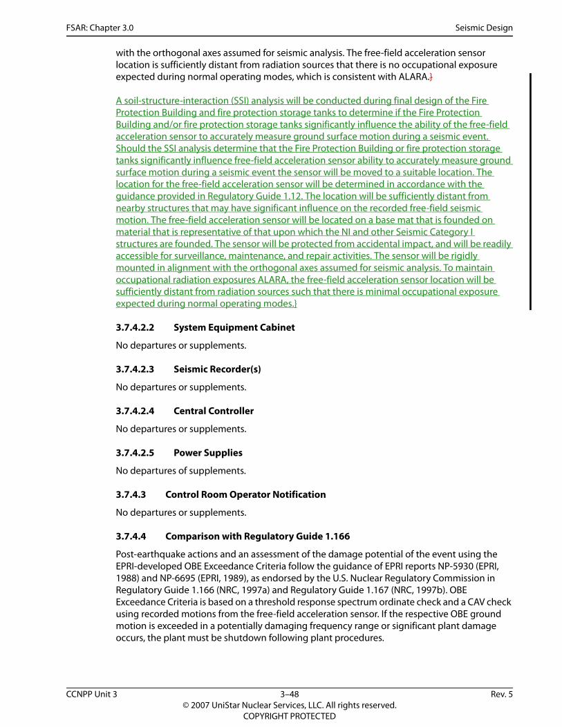
FSAR: Chapter 3.0 Seismic Design
with the orthogonal axes assumed for seismic analysis. The free-field acceleration sensor location is sufficiently distant from radiation sources that there is no occupational exposure expected during normal operating modes, which is consistent with ALARA.}
A soil-structure-interaction (SSI) analysis will be conducted during final design of the Fire Protection Building and fire protection storage tanks to determine if the Fire Protection Building and/or fire protection storage tanks significantly influence the ability of the free-field acceleration sensor to accurately measure ground surface motion during a seismic event. Should the SSI analysis determine that the Fire Protection Building or fire protection storage tanks significantly influence free-field acceleration sensor ability to accurately measure ground surface motion during a seismic event the sensor will be moved to a suitable location. The location for the free-field acceleration sensor will be determined in accordance with the guidance provided in Regulatory Guide 1.12. The location will be sufficiently distant from nearby structures that may have significant influence on the recorded free-field seismic motion. The free-field acceleration sensor will be located on a base mat that is founded on material that is representative of that upon which the NI and other Seismic Category I structures are founded. The sensor will be protected from accidental impact, and will be readily accessible for surveillance, maintenance, and repair activities. The sensor will be rigidly mounted in alignment with the orthogonal axes assumed for seismic analysis. To maintain occupational radiation exposures ALARA, the free-field acceleration sensor location will be sufficiently distant from radiation sources such that there is minimal occupational exposure expected during normal operating modes.}
3.7.4.2.2 System Equipment Cabinet
No departures or supplements.
3.7.4.2.3 Seismic Recorder(s)
No departures or supplements.
3.7.4.2.4 Central Controller
No departures or supplements.
3.7.4.2.5 Power Supplies
No departures of supplements.
3.7.4.3 Control Room Operator Notification
No departures or supplements.
3.7.4.4 Comparison with Regulatory Guide 1.166
Post-earthquake actions and an assessment of the damage potential of the event using the EPRI-developed OBE Exceedance Criteria follow the guidance of EPRI reports NP-5930 (EPRI, 1988) and NP-6695 (EPRI, 1989), as endorsed by the U.S. Nuclear Regulatory Commission in Regulatory Guide 1.166 (NRC, 1997a) and Regulatory Guide 1.167 (NRC, 1997b). OBE Exceedance Criteria is based on a threshold response spectrum ordinate check and a CAV check using recorded motions from the free-field acceleration sensor. If the respective OBE ground motion is exceeded in a potentially damaging frequency range or significant plant damage occurs, the plant must be shutdown following plant procedures.
CCNPP Unit 3 3–48 Rev. 5© 2007 UniStar Nuclear Services, LLC. All rights reserved.
COPYRIGHT PROTECTED
FSAR: Chapter 3.0 Seismic Design
3.7.4.5 Instrument Surveillance
No departures or supplements.
3.7.4.6 Program Implementation
No departures or supplements.
3.7.4.7 References
{ASCE, 2005. Seismic Design Criteria for Structures, Systems, and Components in Nuclear Facilities, ASCE 43-05, American Society of Civil Engineers, January 2005.
EPRI, 1988. A Criterion for Determining Exceedance of the Operating Basis Earthquake, NP-5930, Electric Power Research Institute, July 1988.
EPRI, 1989. Guidelines for Nuclear Plant Response to an Earthquake, NP-6695, Electric Power Research Institute, December 1989.
NRC, 1997a. Pre-Earthquake Planning and Immediate Nuclear Power Plant Operator Post-Earthquake Actions, Regulatory Guide 1.166, Revision 0, U. S. Nuclear Regulatory Commission, March 1997.
NRC, 1997b. Restart of a Nuclear Power Plant Shut Down by a Seismic Event, Regulatory Guide 1.167, Revision 0, U. S. Nuclear Regulatory Commission, March 1997.}
CCNPP Unit 3 3–49 Rev. 5© 2007 UniStar Nuclear Services, LLC. All rights reserved.
COPYRIGHT PROTECTED

FSAR: Chapter 3.0 Seismic Design
Table 3.7-1—{CCNPP Unit 3 Best Estimate Soil Modeling}P-Wave Velocity of Submerged Layer (4,800 fps) = 1,463 m/s
Average Water Table Depth = Top of Layer 1
34 Layers + 05 Sublayers (Halfspace)CCNPP Unit 3 Best Estimate Soil
Layer No.
Depth from 40 ft below grade
(ft) (m)Layer Thk.
(m)
Unit Wt.
(kN/m3)Vs
(m/s)Vs
(fps)Vp
(m/s)S-Damp
RatioP-Damp
RatioPoisson’s
RatioPassing
Frequency1 7.5 2.28 2.28 19.16 442.0 1450.0 1463 0.01 0.0033 0.43 392 15.0 4.56 2.28 19.16 442.0 1450.0 1463 0.01 0.0033 0.43 393 30.0 9.13 4.57 19.16 548.0 1800.0 1820 0.01 0.0033 0.45 244 37.4 11.41 2.28 19.16 344.4 1130.0 1756 0.01 0.0033 0.48 305 44.9 13.69 2.28 19.16 344.4 1130.0 1756 0.01 0.0033 0.48 306 59.9 18.26 4.57 19.16 530.4 1740.0 1759 0.01 0.0033 0.45 237 69.7 21.23 2.97 18.07 381.0 1250.0 1601 0.01 0.0033 0.47 268 79.4 24.20 2.97 18.07 381.0 1250.0 1601 0.01 0.0033 0.47 269 89.2 27.17 2.97 18.07 381.0 1250.0 1601 0.01 0.0033 0.47 26
10 98.9 30.14 2.97 18.07 381.0 1250.0 1601 0.01 0.0033 0.47 2611 108.6 33.11 2.97 18.07 381.0 1250.0 1601 0.01 0.0033 0.47 2612 118.4 36.08 2.97 18.07 381.0 1250.0 1601 0.01 0.0033 0.47 2613 128.1 39.05 2.97 18.07 381.0 1250.0 1601 0.01 0.0033 0.47 2614 137.9 42.02 2.97 18.07 381.0 1250.0 1601 0.01 0.0033 0.47 2615 147.6 44.99 2.97 18.07 381.0 1250.0 1601 0.01 0.0033 0.47 2616 157.4 47.96 2.97 18.07 381.0 1250.0 1601 0.01 0.0033 0.47 2617 167.1 50.96 2.97 18.07 381.0 1250.0 1601 0.01 0.0033 0.47 2618 176.9 53.90 2.97 18.07 381.0 1250.0 1601 0.01 0.0033 0.47 2619 186.6 56.87 2.97 18.07 381.0 1250.0 1601 0.01 0.0033 0.47 2620 196.3 59.84 2.97 18.07 381.0 1250.0 1601 0.01 0.0033 0.47 2621 206.1 62.81 2.97 18.07 381.0 1250.0 1601 0.01 0.0033 0.47 2622 215.8 65.78 2.97 18.07 381.0 1250.0 1601 0.01 0.0033 0.47 2623 225.6 68.75 2.97 18.07 381.0 1250.0 1601 0.01 0.0033 0.47 2624 235.3 71.72 2.97 18.07 381.0 1250.0 1601 0.01 0.0033 0.47 2625 245.1 74.69 2.97 18.07 381.0 1250.0 1601 0.01 0.0033 0.47 2626 255.1 77.74 3.05 18.07 545.6 1790.0 1810 0.01 0.0033 0.45 3627 265.1 80.79 3.05 18.07 545.6 1790.0 1810 0.01 0.0033 0.45 3628 275.1 83.84 3.05 18.07 710.2 2330.0 1912 0.01 0.0033 0.42 4729 288.4 87.90 4.06 18.07 618.7 2030.0 1766 0.01 0.0033 0.43 3030 301.7 91.96 4.06 18.07 618.7 2030.0 1766 0.01 0.0033 0.43 3031 315.0 96.02 4.06 18.07 618.7 2030.0 1766 0.01 0.0033 0.43 3032 330.7 100.80 4.78 18.85 588.3 1930.0 1797 0.01 0.0033 0.44 2533 346.4 105.58 4.78 18.85 588.3 1930.0 1797 0.01 0.0033 0.44 2534 362.1 110.36 4.78 18.85 588.3 1930.0 1797 0.01 0.0033 0.44 25
Halfspace 18.07 670.6 2200.0 1643 0.01 0.0033 0.4
CCNPP Unit 3 3–50 Rev. 5© 2007 UniStar Nuclear Services, LLC. All rights reserved.
COPYRIGHT PROTECTED

FSAR: Chapter 3.0 Seismic Design
Table 3.7-2—{CCNPP Unit 3 Lower Bound Soil Modeling}P-Wave Velocity of Submerged Layer (4,800 fps) = 1,463 m/s
Average Water Table Depth = Top of Layer 1
34 Layers + 05 Sublayers (Halfspace)CCNPP Unit 3 Lower Bound Soil
Layer No.
Depth from 40 ft below grade
(ft) (m)Layer Thk.
(m)
Unit Wt.
(kN/m3)Vs
(m/s)Vs
(fps)Vp
(m/s)S-Damp
RatioP-Damp
RatioPoisson’s
RatioPassing
Frequency1 7.5 2.28 2.28 19.16 312.5 1025.3 1463 0.01 0.0033 0.43 272 15.0 4.56 2.28 19.16 312.5 1025.3 1463 0.01 0.0033 0.43 273 30.0 9.13 4.57 19.16 387.9 1272.8 1463 0.01 0.0033 0.45 174 37.4 11.41 2.28 19.16 243.5 799.0 1463 0.01 0.0033 0.48 215 44.9 13.69 2.28 19.16 243.5 799.0 1463 0.01 0.0033 0.48 216 59.9 18.26 4.57 19.16 375.0 1230.4 1463 0.01 0.0033 0.45 167 69.7 21.23 2.97 18.07 269.4 883.9 1463 0.01 0.0033 0.47 188 79.4 24.20 2.97 18.07 269.4 883.9 1463 0.01 0.0033 0.47 189 89.2 27.17 2.97 18.07 269.4 883.9 1463 0.01 0.0033 0.47 18
10 98.9 30.14 2.97 18.07 269.4 883.9 1463 0.01 0.0033 0.47 1811 108.6 33.11 2.97 18.07 269.4 883.9 1463 0.01 0.0033 0.47 1812 118.4 36.08 2.97 18.07 269.4 883.9 1463 0.01 0.0033 0.47 1813 128.1 39.05 2.97 18.07 269.4 883.9 1463 0.01 0.0033 0.47 1814 137.9 42.02 2.97 18.07 269.4 883.9 1463 0.01 0.0033 0.47 1815 147.6 44.99 2.97 18.07 269.4 883.9 1463 0.01 0.0033 0.47 1816 157.4 47.96 2.97 18.07 269.4 883.9 1463 0.01 0.0033 0.47 1817 167.1 50.93 2.97 18.07 269.4 883.9 1463 0.01 0.0033 0.47 1818 176.9 53.90 2.97 18.07 269.4 883.9 1463 0.01 0.0033 0.47 1819 186.6 56.87 2.97 18.07 269.4 883.9 1463 0.01 0.0033 0.47 1820 196.3 59.84 2.97 18.07 269.4 883.9 1463 0.01 0.0033 0.47 1821 206.1 62.81 2.97 18.07 269.4 883.9 1463 0.01 0.0033 0.47 1822 215.8 65.78 2.97 18.07 269.4 883.9 1463 0.01 0.0033 0.47 1823 225.6 68.75 2.97 18.07 269.4 883.9 1463 0.01 0.0033 0.47 1824 235.3 71.72 2.97 18.07 269.4 883.9 1463 0.01 0.0033 0.47 1825 245.1 74.69 2.97 18.07 269.4 883.9 1463 0.01 0.0033 0.47 1826 255.1 77.74 3.05 18.07 385.8 1265.7 1463 0.01 0.0033 0.45 2527 265.1 80.79 3.05 18.07 385.8 1265.7 1463 0.01 0.0033 0.45 2528 275.1 83.84 3.05 18.07 502.2 1647.6 1463 0.01 0.0033 0.42 3329 288.4 87.90 4.06 18.07 437.5 1435.4 1463 0.01 0.0033 0.43 2230 301.7 91.96 4.06 18.07 437.5 1435.4 1463 0.01 0.0033 0.43 2231 315.0 96.02 4.06 18.07 437.5 1435.4 1463 0.01 0.0033 0.43 2232 330.7 100.80 4.78 18.85 416.0 1364.7 1463 0.01 0.0033 0.44 1733 346.4 105.58 4.78 18.85 416.0 1364.7 1463 0.01 0.0033 0.44 1734 362.1 110.36 4.78 18.85 416.0 1364.7 1463 0.01 0.0033 0.44 17
Halfspace 18.07 416.0 1364.7 1463 0.01 0.0033 0.4
CCNPP Unit 3 3–51 Rev. 5© 2007 UniStar Nuclear Services, LLC. All rights reserved.
COPYRIGHT PROTECTED

FSAR: Chapter 3.0 Seismic Design
Table 3.7-3—{CCNPP Unit 3 Upper Bound Soil Modeling}
P-Wave Velocity of Submerged Layer (4,800 fps) = 1,463 m/sAverage Water Table Depth = Top of Layer 1
34 Layers + 05 Sublayers (Halfspace)CCNPP Unit 3 Upper Bound Soil
Layer No.
Depth from 40 ft below grade
(ft) (m)Layer Thk.
(m)
Unit Wt.
(kN/m3)Vs
(m/s)Vs
(fps)Vp
(m/s)S-Damp
RatioP-Damp
RatioPoisson’s
RatioPassing
Frequency1 7.5 2.28 2.28 19.16 625.0 2050.6 1784 0.01 0.0033 0.43 552 15.0 4.56 2.28 19.16 625.0 2050.6 1784 0.01 0.0033 0.43 553 30.0 9.13 4.57 19.16 775.9 2545.6 2573 0.01 0.0033 0.45 344 37.4 11.41 2.28 19.16 487.1 1598.1 2484 0.01 0.0033 0.48 435 44.9 13.69 2.28 19.16 487.1 1598.1 2484 0.01 0.0033 0.48 436 59.9 18.26 4.57 19.16 750.0 2460.7 2488 0.01 0.0033 0.45 337 69.7 21.23 2.97 18.07 538.8 1767.8 2265 0.01 0.0033 0.47 368 79.4 24.20 2.97 18.07 538.8 1767.8 2265 0.01 0.0033 0.47 369 89.2 27.17 2.97 18.07 538.8 1767.8 2265 0.01 0.0033 0.47 36
10 98.9 30.14 2.97 18.07 538.8 1767.8 2265 0.01 0.0033 0.47 3611 108.6 33.11 2.97 18.07 538.8 1767.8 2265 0.01 0.0033 0.47 3612 118.4 36.08 2.97 18.07 538.8 1767.8 2265 0.01 0.0033 0.47 3613 128.1 39.05 2.97 18.07 538.8 1767.8 2265 0.01 0.0033 0.47 3614 137.9 42.02 2.97 18.07 538.8 1767.8 2265 0.01 0.0033 0.47 3615 147.6 44.99 2.97 18.07 538.8 1767.8 2265 0.01 0.0033 0.47 3616 157.4 47.96 2.97 18.07 538.8 1767.8 2265 0.01 0.0033 0.47 3617 167.1 50.93 2.97 18.07 538.8 1767.8 2265 0.01 0.0033 0.47 3618 176.9 53.90 2.97 18.07 538.8 1767.8 2265 0.01 0.0033 0.47 3619 186.6 56.87 2.97 18.07 538.8 1767.8 2265 0.01 0.0033 0.47 3620 196.3 59.84 2.97 18.07 538.8 1767.8 2265 0.01 0.0033 0.47 3621 206.1 62.81 2.97 18.07 538.8 1767.8 2265 0.01 0.0033 0.47 3622 215.8 65.78 2.97 18.07 538.8 1767.8 2265 0.01 0.0033 0.47 3623 225.6 68.75 2.97 18.07 538.8 1767.8 2265 0.01 0.0033 0.47 3624 235.3 71.72 2.97 18.07 538.8 1767.8 2265 0.01 0.0033 0.47 3625 245.1 74.69 2.97 18.07 538.8 1767.8 2265 0.01 0.0033 0.47 3626 255.1 77.74 3.05 18.07 771.6 2531.4 2559 0.01 0.0033 0.45 5127 265.1 80.79 3.05 18.07 771.6 2531.4 2559 0.01 0.0033 0.45 5128 275.1 83.84 3.05 18.07 1004.4 3295.1 2704 0.01 0.0033 0.42 6629 288.4 87.90 4.06 18.07 875.0 2870.9 2497 0.01 0.0033 0.43 4330 301.7 91.96 4.06 18.07 875.0 2870.9 2497 0.01 0.0033 0.43 4331 315.0 96.02 4.06 18.07 875.0 2870.9 2497 0.01 0.0033 0.43 4332 330.7 100.80 4.78 18.85 831.9 2729.4 2542 0.01 0.0033 0.44 3533 346.4 105.58 4.78 18.85 831.9 2729.4 2542 0.01 0.0033 0.44 3534 362.1 110.36 4.78 18.85 831.9 2729.4 2542 0.01 0.0033 0.44 35
Halfspace 18.07 948.3 3111.3 2323 0.01 0.0033 0.4
CCNPP Unit 3 3–52 Rev. 5© 2007 UniStar Nuclear Services, LLC. All rights reserved.
COPYRIGHT PROTECTED
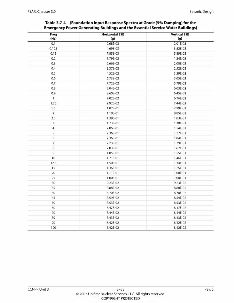
FSAR: Chapter 3.0 Seismic Design
Table 3.7-4—{Foundation Input Response Spectra at Grade (5% Damping) for the Emergency Power Generating Buildings and the Essential Service Water Buildings}
Freq(Hz)
Horizontal SSE(g)
Vertical SSE(g)
0.1 2.68E-03 2.01E-030.125 4.69E-03 3.52E-030.15 7.85E-03 5.89E-030.2 1.79E-02 1.34E-020.3 2.66E-02 2.00E-020.4 3.37E-02 2.52E-020.5 4.52E-02 3.39E-020.6 6.73E-02 5.05E-020.7 7.72E-02 5.79E-020.8 8.04E-02 6.03E-020.9 8.60E-02 6.45E-021 9.02E-02 6.76E-02
1.25 9.92E-02 7.44E-021.5 1.07E-01 7.99E-022 1.18E-01 8.85E-02
2.5 1.38E-01 1.03E-013 1.73E-01 1.30E-014 2.06E-01 1.54E-015 2.36E-01 1.77E-016 2.36E-01 1.84E-017 2.23E-01 1.79E-018 2.03E-01 1.67E-019 1.85E-01 1.55E-01
10 1.71E-01 1.46E-0112.5 1.50E-01 1.34E-0115 1.36E-01 1.25E-0120 1.11E-01 1.08E-0125 1.00E-01 1.00E-0130 9.23E-02 9.23E-0235 8.88E-02 8.88E-0240 8.70E-02 8.70E-0245 8.59E-02 8.59E-0250 8.53E-02 8.53E-0260 8.47E-02 8.47E-0270 8.44E-02 8.44E-0280 8.43E-02 8.43E-0290 8.42E-02 8.42E-02
100 8.42E-02 8.42E-02
CCNPP Unit 3 3–53 Rev. 5© 2007 UniStar Nuclear Services, LLC. All rights reserved.
COPYRIGHT PROTECTED

FSAR: Chapter 3.0 Seismic Design
Note: All directions are with respect to Maryland CCNPP Plant North
Table 3.7-5—{UHS Makeup Water Intake Structure Dominant Frequencies for the 6 Soil Cases}
Soil Case EmbedmentEast-WestNorth-South
(X) FrequencyVertical (Y) Frequency
North-SouthEast-West (Z) Frequency
50 Percent Soil Shear Modulus
No 2.60 Hz 3.71 Hz 2.64 Hz
100 Percent Soil Shear Modulus
No 3.65 Hz 5.24 Hz 3.66 Hz
200 Percent Soil Shear Modulus
No 5.06 Hz 7.36 Hz 4.99 Hz
50 Percent Soil Shear Modulus
Yes 3.61 Hz 4.43 Hz 3.63 Hz
100 Percent Soil Shear Modulus
Yes 5.02 Hz 6.25 Hz 4.97 Hz
200 Percent Soil Shear Modulus
Yes 6.86 Hz 8.77 Hz 6.60 Hz
CCNPP Unit 3 3–54 Rev. 5© 2007 UniStar Nuclear Services, LLC. All rights reserved.
COPYRIGHT PROTECTED

FSAR: Chapter 3.0 Seismic Design
Note: X-Direction is MD East-WestCCNPP Plant North-South, Y-Direction is Vertical and Z-Direction is North-SouthEast-West.
Table 3.7-6—{UHS Makeup Water Intake Structure Response Accelerations for Equivalent Static Analysis}
ComponentSSE (X-Direction, g) SSE (Z-Direction, g) SSE (Y-Direction, g)
Ax Az Ay Ax Az Ay Ax Az Ay
Base MatBasemat(Elevation -20.5-22.5 ft or
-6.25-6.86 m)
0.27 0.00 0.09 0.02 0.24 0.07 0.07 0.00 0.30
Operating Deck(Elevation 11.5 ft or 3.50m)
0.30 0.00 0.11 0.02 0.35 0.08 0.05 0.00 0.31
Roof Slab(Elevation 26.5 ft or 8.08m)
0.39 0.00 0.15 0.02 0.38 0.08 0.09 0.00 0.33
CCNPP Unit 3 3–55 Rev. 5© 2007 UniStar Nuclear Services, LLC. All rights reserved.
COPYRIGHT PROTECTED

FSAR: Chapter 3.0 Seismic Design
Table 3.7-7—{UHS Makeup Water Intake Structure Natural Frequencies and Mass Participation (Soil Case with 50% Shear Modulus and without Soil Embedment)}
ModeFrequency
(Hz)
X- dir Mass Participation
(%)
Cumulative X-dir Modal
Mass (%)
Y- dir Mass Participation
(%)
Cumulative Y-dir Modal
Mass (%)
Z- dir Mass Participation
(%)
Cumulative Z-dir Modal
Mass (%)1 2.60 83.28 83.28 2.25 2.25 0.00 0.002 2.64 0.00 83.28 0.00 2.25 86.53 86.543 3.71 3.92 87.20 95.25 97.50 0.00 86.544 4.30 0.00 87.20 0.00 97.50 2.20 88.735 5.59 12.79 99.99 2.50 100.00 0.00 88.736 5.91 0.00 99.99 0.00 100.00 11.22 99.957 14.66 0.00 99.99 0.00 100.00 0.00 99.968 18.34 0.01 100.00 0.00 100.00 0.00 99.969 18.97 0.00 100.00 0.00 100.00 0.00 99.96
10 20.95 0.00 100.00 0.00 100.00 0.00 99.9611 21.37 0.00 100.00 0.00 100.00 0.00 99.9612 21.72 0.00 100.00 0.00 100.00 0.00 99.9613 23.02 0.00 100.00 0.00 100.00 0.04 100.0014 28.20 0.00 100.00 0.00 100.00 0.00 100.0015 33.38 0.00 100.00 0.00 100.00 0.00 100.0016 34.23 0.00 100.00 0.00 100.00 0.00 100.0017 34.96 0.00 100.00 0.00 100.00 0.00 100.0018 35.52 0.00 100.00 0.00 100.00 0.00 100.0019 35.99 0.00 100.00 0.00 100.00 0.00 100.0020 36.96 0.00 100.00 0.00 100.00 0.00 100.0021 37.49 0.00 100.00 0.00 100.00 0.00 100.0022 40.35 0.00 100.00 0.00 100.00 0.00 100.0023 41.76 0.00 100.00 0.00 100.00 0.00 100.0024 44.31 0.00 100.00 0.00 100.00 0.00 100.0025 44.55 0.00 100.00 0.00 100.00 0.00 100.0026 46.72 0.00 100.00 0.00 100.00 0.00 100.0027 47.18 0.00 100.00 0.00 100.00 0.00 100.0028 47.84 0.00 100.00 0.00 100.00 0.00 100.0029 48.19 0.00 100.00 0.00 100.00 0.00 100.0030 48.49 0.00 100.00 0.00 100.00 0.00 100.00
CCNPP Unit 3 3–56 Rev. 5© 2007 UniStar Nuclear Services, LLC. All rights reserved.
COPYRIGHT PROTECTED

FSAR: Chapter 3.0 Seismic Design
Table 3.7-8— {UHS Makeup Water Intake Structure Natural Frequencies and Mass Participation (Soil Case with 100% Shear Modulus and without Soil Embedment)}
ModeFrequency
(Hz)
X- dir Mass Participation
(%)
Cumulative X-dir Modal
Mass (%)
Y- dir Mass Participation
(%)
Cumulative Y-dir Modal
Mass (%)
Z- dir Mass Participation
(%)
Cumulative Z-dir Modal
Mass (%)1 3.65 82.67 82.67 2.24 2.24 0.05 0.052 3.66 0.05 82.72 0.00 2.24 86.59 86.643 5.24 4.09 86.82 94.91 97.15 0.00 86.654 5.93 0.00 86.82 0.00 97.15 1.66 88.315 7.79 13.13 99.95 2.84 99.99 0.00 88.316 8.30 0.00 99.95 0.00 99.99 11.52 99.837 14.68 0.00 99.95 0.00 99.99 0.01 99.848 18.59 0.03 99.98 0.00 99.99 0.00 99.849 19.00 0.01 99.98 0.00 100.00 0.00 99.84
10 20.96 0.00 99.98 0.00 100.00 0.00 99.8411 21.37 0.00 99.98 0.00 100.00 0.00 99.8412 21.72 0.00 99.98 0.00 100.00 0.00 99.8413 23.77 0.00 99.98 0.00 100.00 0.15 99.9914 28.29 0.00 99.98 0.00 100.00 0.00 99.9915 33.52 0.00 99.99 0.00 100.00 0.00 99.9916 34.24 0.00 99.99 0.00 100.00 0.00 99.9917 34.96 0.00 99.99 0.00 100.00 0.00 99.9918 35.52 0.00 99.99 0.00 100.00 0.00 99.9919 36.02 0.00 99.99 0.00 100.00 0.00 99.9920 37.00 0.00 99.99 0.00 100.00 0.00 99.9921 37.54 0.00 99.99 0.00 100.00 0.00 99.9922 40.60 0.00 99.99 0.00 100.00 0.00 100.0023 41.89 0.00 100.00 0.00 100.00 0.00 100.0024 44.40 0.00 100.00 0.00 100.00 0.00 100.0025 44.59 0.00 100.00 0.00 100.00 0.00 100.0026 46.73 0.00 100.00 0.00 100.00 0.00 100.0027 47.19 0.00 100.00 0.00 100.00 0.00 100.0028 47.85 0.00 100.00 0.00 100.00 0.00 100.0029 48.20 0.00 100.00 0.00 100.00 0.00 100.0030 48.51 0.00 100.00 0.00 100.00 0.00 100.00
CCNPP Unit 3 3–57 Rev. 5© 2007 UniStar Nuclear Services, LLC. All rights reserved.
COPYRIGHT PROTECTED

FSAR: Chapter 3.0 Seismic Design
Table 3.7-9— {UHS Makeup Water Intake Structure Natural Frequencies and Mass Participation (Soil Case with 200% Shear Modulus and without Soil Embedment)}
ModeFrequency
(Hz)
X- dir Mass Participation
(%)
Cumulative X-dir Modal
Mass (%)
Y- dir Mass Participation
(%)
Cumulative Y-dir Modal
Mass (%)
Z- dir Mass Participation
(%)
Cumulative Z-dir Modal
Mass (%)1.0 4.99 0.01 0.01 0.00 0.00 86.53 86.532.0 5.06 81.50 81.51 2.24 2.24 0.01 86.543.0 7.36 4.54 86.04 93.96 96.21 0.00 86.544.0 8.01 0.00 86.04 0.00 96.21 0.84 87.385.0 10.65 13.66 99.71 3.77 99.98 0.00 87.386.0 11.54 0.00 99.71 0.00 99.98 11.88 99.267.0 14.76 0.00 99.71 0.00 99.98 0.21 99.488.0 18.88 0.02 99.73 0.00 99.98 0.00 99.489.0 19.40 0.21 99.94 0.00 99.98 0.00 99.48
10.0 20.96 0.00 99.94 0.00 99.98 0.00 99.4811.0 21.37 0.00 99.94 0.00 99.98 0.00 99.4812.0 21.72 0.00 99.94 0.00 99.98 0.00 99.4813.0 25.23 0.00 99.94 0.00 99.98 0.47 99.9514.0 28.47 0.00 99.94 0.00 99.98 0.00 99.9515.0 33.79 0.00 99.94 0.00 99.98 0.00 99.9516.0 34.27 0.00 99.94 0.00 99.98 0.00 99.9517.0 34.96 0.00 99.94 0.00 99.98 0.00 99.9618.0 35.54 0.00 99.94 0.00 99.98 0.00 99.9619.0 36.07 0.00 99.95 0.00 99.98 0.01 99.9720.0 37.07 0.01 99.95 0.00 99.98 0.00 99.9721.0 37.63 0.02 99.97 0.00 99.99 0.00 99.9722.0 41.05 0.00 99.97 0.00 99.99 0.01 99.9823.0 42.15 0.02 99.99 0.00 99.99 0.00 99.9824.0 44.49 0.00 99.99 0.00 99.99 0.00 99.9825.0 44.81 0.00 99.99 0.00 99.99 0.00 99.9826.0 46.76 0.00 99.99 0.00 99.99 0.00 99.9827.0 47.22 0.00 99.99 0.00 99.99 0.00 99.9828.0 47.85 0.00 99.99 0.00 99.99 0.00 99.9829.0 48.22 0.00 99.99 0.00 99.99 0.00 99.9830.0 48.54 0.00 99.99 0.00 99.99 0.00 99.98
CCNPP Unit 3 3–58 Rev. 5© 2007 UniStar Nuclear Services, LLC. All rights reserved.
COPYRIGHT PROTECTED

FSAR: Chapter 3.0 Seismic Design
Table 3.7-10— {UHS Makeup Water Intake Structure Natural Frequencies and Mass Participation (Soil Case with 50% Shear Modulus and with Soil Embedment)}
Mode Frequency (Hz)
X- dir Mass Participation
(%)
Cumulative X-dir Modal
Mass (%)
Y- dir Mass Participation
(%)
Cumulative Y-dir Modal
Mass (%)
Z- dir Mass Participation
(%)
Cumulative Z-dir Modal
Mass (%)1 3.61 90.02 90.02 2.56 2.56 0.02 0.022 3.63 0.01 90.04 0.00 2.56 93.30 93.313 4.43 3.15 93.19 96.66 99.22 0.00 93.314 6.48 0.00 93.19 0.00 99.22 1.11 94.435 8.13 6.77 99.96 0.77 100.00 0.00 94.436 8.87 0.00 99.96 0.00 100.00 5.47 99.907 14.70 0.00 99.96 0.00 100.00 0.01 99.918 18.74 0.02 99.98 0.00 100.00 0.00 99.919 19.07 0.01 99.99 0.00 100.00 0.00 99.91
10 20.96 0.00 99.99 0.00 100.00 0.00 99.9111 21.37 0.00 99.99 0.00 100.00 0.00 99.9112 21.72 0.00 99.99 0.00 100.00 0.00 99.9113 25.19 0.00 99.99 0.00 100.00 0.08 99.9914 29.90 0.00 99.99 0.00 100.00 0.00 99.9915 34.33 0.00 99.99 0.00 100.00 0.00 99.9916 34.87 0.00 99.99 0.00 100.00 0.00 99.9917 34.97 0.00 99.99 0.00 100.00 0.00 99.9918 35.59 0.00 99.99 0.00 100.00 0.00 99.9919 36.09 0.00 99.99 0.00 100.00 0.00 100.0020 37.13 0.00 99.99 0.00 100.00 0.00 100.0021 37.63 0.00 100.00 0.00 100.00 0.00 100.0022 41.54 0.00 100.00 0.00 100.00 0.00 100.0023 43.07 0.00 100.00 0.00 100.00 0.00 100.0024 44.56 0.00 100.00 0.00 100.00 0.00 100.0025 46.61 0.00 100.00 0.00 100.00 0.00 100.0026 47.11 0.00 100.00 0.00 100.00 0.00 100.0027 47.59 0.00 100.00 0.00 100.00 0.00 100.0028 47.90 0.00 100.00 0.00 100.00 0.00 100.0029 48.32 0.00 100.00 0.00 100.00 0.00 100.0030 48.63 0.00 100.00 0.00 100.00 0.00 100.00
CCNPP Unit 3 3–59 Rev. 5© 2007 UniStar Nuclear Services, LLC. All rights reserved.
COPYRIGHT PROTECTED
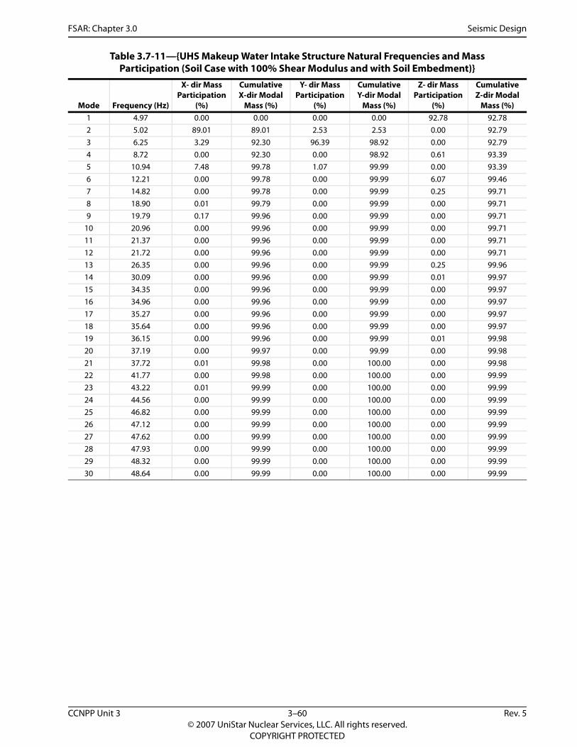
FSAR: Chapter 3.0 Seismic Design
Table 3.7-11—{UHS Makeup Water Intake Structure Natural Frequencies and Mass Participation (Soil Case with 100% Shear Modulus and with Soil Embedment)}
Mode Frequency (Hz)
X- dir Mass Participation
(%)
Cumulative X-dir Modal
Mass (%)
Y- dir Mass Participation
(%)
Cumulative Y-dir Modal
Mass (%)
Z- dir Mass Participation
(%)
Cumulative Z-dir Modal
Mass (%)1 4.97 0.00 0.00 0.00 0.00 92.78 92.782 5.02 89.01 89.01 2.53 2.53 0.00 92.793 6.25 3.29 92.30 96.39 98.92 0.00 92.794 8.72 0.00 92.30 0.00 98.92 0.61 93.395 10.94 7.48 99.78 1.07 99.99 0.00 93.396 12.21 0.00 99.78 0.00 99.99 6.07 99.467 14.82 0.00 99.78 0.00 99.99 0.25 99.718 18.90 0.01 99.79 0.00 99.99 0.00 99.719 19.79 0.17 99.96 0.00 99.99 0.00 99.71
10 20.96 0.00 99.96 0.00 99.99 0.00 99.7111 21.37 0.00 99.96 0.00 99.99 0.00 99.7112 21.72 0.00 99.96 0.00 99.99 0.00 99.7113 26.35 0.00 99.96 0.00 99.99 0.25 99.9614 30.09 0.00 99.96 0.00 99.99 0.01 99.9715 34.35 0.00 99.96 0.00 99.99 0.00 99.9716 34.96 0.00 99.96 0.00 99.99 0.00 99.9717 35.27 0.00 99.96 0.00 99.99 0.00 99.9718 35.64 0.00 99.96 0.00 99.99 0.00 99.9719 36.15 0.00 99.96 0.00 99.99 0.01 99.9820 37.19 0.00 99.97 0.00 99.99 0.00 99.9821 37.72 0.01 99.98 0.00 100.00 0.00 99.9822 41.77 0.00 99.98 0.00 100.00 0.00 99.9923 43.22 0.01 99.99 0.00 100.00 0.00 99.9924 44.56 0.00 99.99 0.00 100.00 0.00 99.9925 46.82 0.00 99.99 0.00 100.00 0.00 99.9926 47.12 0.00 99.99 0.00 100.00 0.00 99.9927 47.62 0.00 99.99 0.00 100.00 0.00 99.9928 47.93 0.00 99.99 0.00 100.00 0.00 99.9929 48.32 0.00 99.99 0.00 100.00 0.00 99.9930 48.64 0.00 99.99 0.00 100.00 0.00 99.99
CCNPP Unit 3 3–60 Rev. 5© 2007 UniStar Nuclear Services, LLC. All rights reserved.
COPYRIGHT PROTECTED

FSAR: Chapter 3.0 Seismic Design
Table 3.7-12— {UHS Makeup Water Intake Structure Natural Frequencies and Mass Participation (Soil Case with 200% Shear Modulus and with Soil Embedment)}
Mode Frequency (Hz)
X- dir Mass Participation
(%)
Cumulative X-dir Modal
Mass (%)
Y- dir Mass Participation
(%)
Cumulative Y-dir Modal
Mass (%)
Z- dir Mass Participation
(%)
Cumulative Z-dir Modal
Mass (%)1 6.60 0.00 0.00 0.00 0.00 91.23 91.232 6.86 86.48 86.48 2.53 2.53 0.00 91.233 8.77 3.80 90.28 95.34 97.86 0.00 91.234 11.25 0.00 90.28 0.00 97.86 0.06 91.295 13.77 8.38 98.66 2.06 99.92 0.01 91.306 14.43 0.17 98.83 0.04 99.96 1.02 92.327 17.11 0.00 98.83 0.00 99.96 6.85 99.188 18.93 0.00 98.83 0.00 99.96 0.00 99.189 20.96 0.00 98.83 0.00 99.96 0.01 99.18
10 21.37 0.00 98.83 0.00 99.96 0.00 99.1811 21.72 0.00 98.83 0.00 99.96 0.00 99.1912 22.08 1.02 99.86 0.00 99.97 0.00 99.1913 28.16 0.00 99.86 0.00 99.97 0.53 99.7214 30.84 0.00 99.86 0.00 99.97 0.15 99.8715 34.37 0.00 99.86 0.00 99.97 0.00 99.8716 34.97 0.00 99.86 0.00 99.97 0.00 99.8717 35.55 0.00 99.86 0.00 99.97 0.01 99.8818 36.14 0.00 99.86 0.00 99.97 0.01 99.8919 36.31 0.00 99.86 0.00 99.97 0.03 99.9220 37.30 0.01 99.87 0.00 99.97 0.01 99.9321 37.91 0.05 99.93 0.01 99.98 0.00 99.9322 42.19 0.00 99.93 0.00 99.98 0.02 99.9523 43.52 0.04 99.96 0.01 99.99 0.00 99.9524 44.56 0.00 99.96 0.00 99.99 0.00 99.9525 47.14 0.00 99.97 0.00 99.99 0.00 99.9526 47.16 0.00 99.97 0.00 99.99 0.00 99.9527 47.71 0.00 99.97 0.00 99.99 0.00 99.9528 48.06 0.00 99.97 0.00 99.99 0.01 99.9629 48.34 0.00 99.97 0.00 99.99 0.00 99.9630 48.67 0.00 99.97 0.00 99.99 0.00 99.96
CCNPP Unit 3 3–61 Rev. 5© 2007 UniStar Nuclear Services, LLC. All rights reserved.
COPYRIGHT PROTECTED

FSAR: Chapter 3.0
Seismic D
esign
CCNPP U
nit 33–62
Rev.5©
2007 UniStar N
uclear Services, LLC. All rights reserved.
COPYRIG
HT PRO
TECTED
n Base Mat Structures}
100
Figure 3.7-1—{CCNPP Unit 3 GMRS and EUR CSDRS (Horizontal) for the Nuclear Island Commo
Comparison of Ground Design SpectraHorizontal Direction, 5% Damping
0
0.1
0.2
0.3
0.4
0.5
0.6
0.7
0.8
0.9
1
0.1 1 10
Frequency (Hz)
Acc
eler
atio
n (g
)
EUR Hard Soil
EUR Medium Soil
EUR Soft Soil
Calvert Cliffs Unit 3 GMRS

FSAR: Chapter 3.0
Seismic D
esign
CCNPP U
nit 33–63
Rev.5©
2007 UniStar N
uclear Services, LLC. All rights reserved.
COPYRIG
HT PRO
TECTED
Base Mat Structures}
100
Figure 3.7-2—{CCNPP Unit 3 GMRS and EUR CSDRS (Vertical) for the Nuclear Island Common
Comparison of Ground Design SpectraVertical Direction, 5% Damping
0
0.1
0.2
0.3
0.4
0.5
0.6
0.7
0.8
0.9
1
0.1 1 10
Frequency (Hz)
Acc
eler
atio
n (g
)
EUR Hard Soil
EUR Medium Soil
EUR Soft Soil
Calvert Cliffs Unit 3 GMRS

FSAR: Chapter 3.0
Seismic D
esign
CCNPP U
nit 33–64
Rev.5©
2007 UniStar N
uclear Services, LLC. All rights reserved.
COPYRIG
HT PRO
TECTED
.1g PGA (Horizontal)}
t 0.1g PGA (Horizontal)}
100
Figure 3.7-3—{CCNPP Unit 3 GMRS and EUR Certified Seismic Design Response Spectra at 0
Figure 3.7-3 --- {CCNPP Unit 3 GMRS and EUR Certified Seismic Design Response Spectra a
Comparison of EUR Design (0.1g PGA) SpectraHorizontal Direction, 5% Damping
0
0.05
0.1
0.15
0.2
0.25
0.3
0.35
0.1 1 10
Frequency (Hz)
Acc
eler
atio
n (g
)
EUR Hard Soil 0.1g PGA
EUR Medium Soil 0.1g PGA
EUR Soft Soil 0.1g PGA
Calvert Cliffs Unit 3 GMRS
Calvert Cliffs Unit 3 Minimum SSE

FSAR: Chapter 3.0
Seismic D
esign
CCNPP U
nit 33–65
Rev.5©
2007 UniStar N
uclear Services, LLC. All rights reserved.
COPYRIG
HT PRO
TECTED
Low Frequency (Horizontal)}
Low Frequency (Horizontal)}
1
g PGA
l 0.1g PGA
g PGA
3 GMRS
3 Minimum SSE
Figure 3.7-4—{CCNPP Unit 3 GMRS and EUR Certified Seismic Design Response Spectra at 0.1g PGA
Figure 3.7-4 --- {CCNPP Unit 3 GMRS and EUR Certified Seismic Design Response Spectra at 0.1g PGA
Comparison of EUR Design (0.1g PGA) SpectraHorizontal Direction, 5% Damping
0.001
0.01
0.1
0.1
Frequency (Hz)
Acc
eler
atio
n (g
)
EUR Hard Soil 0.1
EUR Medium Soi
EUR Soft Soil 0.1
Calvert Cliffs Unit
Calvert Cliffs Unit

FSAR: Chapter 3.0
Seismic D
esign
CCNPP U
nit 33–66
Rev.5©
2007 UniStar N
uclear Services, LLC. All rights reserved.
COPYRIG
HT PRO
TECTED
0.1g PGA (Vertical)}.1g PGA (Vertical)}
100
Figure 3.7-5—{CCNPP Unit 3 GMRS and EUR Certified Seismic Design Response Spectra atFigure 3.7-5 --- {CCNPP Unit 3 GMRS and EUR Certified Seismic Design Response Spectra at 0
Comparison of EUR Soft 0.1g PGA SpectraVertical Direction, 5% Damping
0
0.05
0.1
0.15
0.2
0.25
0.3
0.35
0.1 1 10
Frequency (Hz)
Acc
eler
atio
n (g
)
EUR Soft Soil 0.1g PGA
Calvert Cliffs Unit 3 GMRS

FSAR: Chapter 3.0
Seismic D
esign
CCNPP U
nit 33–67
Rev.5©
2007 UniStar N
uclear Services, LLC. All rights reserved.
COPYRIG
HT PRO
TECTED
,000 1,200
-656
-556
-456
-356
-256
-156
-56
3,500
Dep
th b
elow
40
ft fr
om G
rade
(ft)
CCNPP3 BE
CCNPP3 LB
CCNPP3 UB
Figure 3.7-6—{CCNPP Unit 3 Low Strain Soil Profiles}
CCNPP Unit 3 Low-Strain Soil Profiles
-200
-180
-160
-140
-120
-100
-80
-60
-40
-20
00 200 400 600 800 1
Shear Wave Velocity, Vs (m/s)
Dep
th b
elow
12.
2m fr
om G
rade
(m)
0 500 1,000 1,500 2,000 2,500 3,000
Shear Wave Velocity, Vs (ft/s)

FSAR: Chapter 3.0
Seismic D
esign
CCNPP U
nit 33–68
Rev.5©
2007 UniStar N
uclear Services, LLC. All rights reserved.
COPYRIG
HT PRO
TECTED
sis}
sis
2,000
-656
-556
-456
-356
-256
-156
-56
Dep
th (f
t)
Case 1uCase 2uCase 3uCase 4uCase 5uCase 1n2uCase 2n3uCase 2sn4uCase 3r3uCCNPP3 BECCNPP3 LBCCNPP3 UB
Figure 3.7-7—{EPR DC Soil Cases vs. CCNPP Unit 3 Soil Cases for SSI Analy
Note: Due to the scale selected for plotting, generic soil case 5a is not shown.
EPR DC Soil Cases vs CCNPP Unit 3 Soil Cases for SSI Analy
-200
-180
-160
-140
-120
-100
-80
-60
-40
-20
00 200 400 600 800 1,000 1,200 1,400 1,600 1,800
Shear Wave Velocity, Vs (m/s)
Dep
th (m
)
0 1,000 2,000 3,000 4,000 5,000 6,000
Shear Wave Velocity, Vs (ft/s)
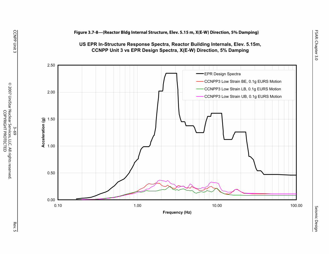
FSAR: Chapter 3.0
Seismic D
esign
CCNPP U
nit 33–69
Rev.5©
2007 UniStar N
uclear Services, LLC. All rights reserved.
COPYRIG
HT PRO
TECTED
Damping}
lev. 5.15m,ping
100.00
tra
in BE, 0.1g EURS Motion
in LB, 0.1g EURS Motion
in UB, 0.1g EURS Motion
Figure 3.7-8—{Reactor Bldg Internal Structure, Elev. 5.15 m, X(E-W) Direction, 5%
US EPR In-Structure Response Spectra, Reactor Building Internals, ECCNPP Unit 3 vs EPR Design Spectra, X(E-W) Direction, 5% Dam
0.00
0.50
1.00
1.50
2.00
2.50
0.10 1.00 10.00
Frequency (Hz)
Acc
eler
atio
n (g
)
EPR Design Spec
CCNPP3 Low Stra
CCNPP3 Low Stra
CCNPP3 Low Stra

FSAR: Chapter 3.0
Seismic D
esign
CCNPP U
nit 33–70
Rev.5©
2007 UniStar N
uclear Services, LLC. All rights reserved.
COPYRIG
HT PRO
TECTED
Damping}
lev. 5.15m,ping
100.00
a
BE, 0.1g EURS Motion
LB, 0.1g EURS Motion
UB, 0.1g EURS Motion
Figure 3.7-9—{Reactor Bldg Internal Structure, Elev. 5.15 m, Y(N-S) Direction, 5%
US EPR In-Structure Response Spectra, Reactor Building Internals, ECCNPP Unit 3 vs EPR Design Spectra, Y(N-S) Direction, 5% Dam
0.00
0.50
1.00
1.50
2.00
2.50
0.10 1.00 10.00
Frequency (Hz)
Acc
eler
atio
n (g
)
EPR Design Spectr
CCNPP3 Low Strain
CCNPP3 Low Strain
CCNPP3 Low Strain

FSAR: Chapter 3.0
Seismic D
esign
CCNPP U
nit 33–71
Rev.5©
2007 UniStar N
uclear Services, LLC. All rights reserved.
COPYRIG
HT PRO
TECTED
Damping}
lev. 5.15m,ping
100.00
Figure 3.7-10—{Reactor Bldg Internal Structure, Elev. 5.15 m, Z(Vert) Direction, 5%
US EPR In-Structure Response Spectra, Reactor Building Internals, ECCNPP Unit 3 vs EPR Design Spectra, Z(Vert) Direction, 5% Dam
0.00
0.50
1.00
1.50
2.00
2.50
0.10 1.00 10.00
Frequency (Hz)
Acc
eler
atio
n (g
)
EPR Design Spectra
CCNPP3 Low Strain BE, 0.1g EURS Motion
CCNPP3 Low Strain LB, 0.1g EURS Motion
CCNPP3 Low Strain UB, 0.1g EURS Motion

FSAR: Chapter 3.0
Seismic D
esign
CCNPP U
nit 33–72
Rev.5©
2007 UniStar N
uclear Services, LLC. All rights reserved.
COPYRIG
HT PRO
TECTED
Damping}
lev. 19.5m,ping
100.00
ra
in BE, 0.1g EURS Motion
in LB, 0.1g EURS Motion
in UB, 0.1g EURS Motion
Figure 3.7-11—{Reactor Bldg Internal Structure, Elev. 19.5 m, X(E-W) Direction, 5%
US EPR In-Structure Response Spectra, Reactor Building Internals, ECCNPP Unit 3 vs EPR Design Spectra, X(E-W) Direction, 5% Dam
0.00
0.50
1.00
1.50
2.00
2.50
3.00
3.50
0.10 1.00 10.00
Frequency (Hz)
Acc
eler
atio
n (g
)
EPR Design Spect
CCNPP3 Low Stra
CCNPP3 Low Stra
CCNPP3 Low Stra
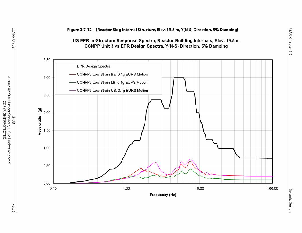
FSAR: Chapter 3.0
Seismic D
esign
CCNPP U
nit 33–73
Rev.5©
2007 UniStar N
uclear Services, LLC. All rights reserved.
COPYRIG
HT PRO
TECTED
Damping}
lev. 19.5m,ping
100.00
Figure 3.7-12—{Reactor Bldg Internal Structure, Elev. 19.5 m, Y(N-S) Direction, 5%
US EPR In-Structure Response Spectra, Reactor Building Internals, ECCNPP Unit 3 vs EPR Design Spectra, Y(N-S) Direction, 5% Dam
0.00
0.50
1.00
1.50
2.00
2.50
3.00
3.50
0.10 1.00 10.00
Frequency (Hz)
Acc
eler
atio
n (g
)
EPR Design Spectra
CCNPP3 Low Strain BE, 0.1g EURS Motion
CCNPP3 Low Strain LB, 0.1g EURS Motion
CCNPP3 Low Strain UB, 0.1g EURS Motion

FSAR: Chapter 3.0
Seismic D
esign
CCNPP U
nit 33–74
Rev.5©
2007 UniStar N
uclear Services, LLC. All rights reserved.
COPYRIG
HT PRO
TECTED
Damping}
lev. 19.5m,ping
100.00
Figure 3.7-13—{Reactor Bldg Internal Structure, Elev. 19.5 m, Z(Vert) Direction, 5%
US EPR In-Structure Response Spectra, Reactor Building Internals, ECCNPP Unit 3 vs EPR Design Spectra, Z(Vert) Direction, 5% Dam
0.00
1.00
2.00
3.00
4.00
5.00
6.00
0.10 1.00 10.00
Frequency (Hz)
Acc
eler
atio
n (g
)
EPR Design Spectra
CCNPP3 Low Strain BE, 0.1g EURS Motion
CCNPP3 Low Strain LB, 0.1g EURS Motion
CCNPP3 Low Strain UB, 0.1g EURS Motion

FSAR: Chapter 3.0
Seismic D
esign
CCNPP U
nit 33–75
Rev.5©
2007 UniStar N
uclear Services, LLC. All rights reserved.
COPYRIG
HT PRO
TECTED
ping}
v. 8.1m,ping
100.00
tra
ain BE, 0.1g EURS Motion
ain LB, 0.1g EURS Motion
ain UB, 0.1g EURS Motion
Figure 3.7-14—{Safeguard Building 1, Elev. 8.1 m, X(E-W) Direction, 5% Dam
US EPR In-Structure Response Spectra, Safeguard Building 1, EleCCNPP Unit 3 vs EPR Design Spectra, X(E-W) Direction, 5% Dam
0.00
0.50
1.00
1.50
2.00
2.50
3.00
0.10 1.00 10.00
Frequency (Hz)
Acc
eler
atio
n (g
)
EPR Design Spec
CCNPP3 Low Str
CCNPP3 Low Str
CCNPP3 Low Str
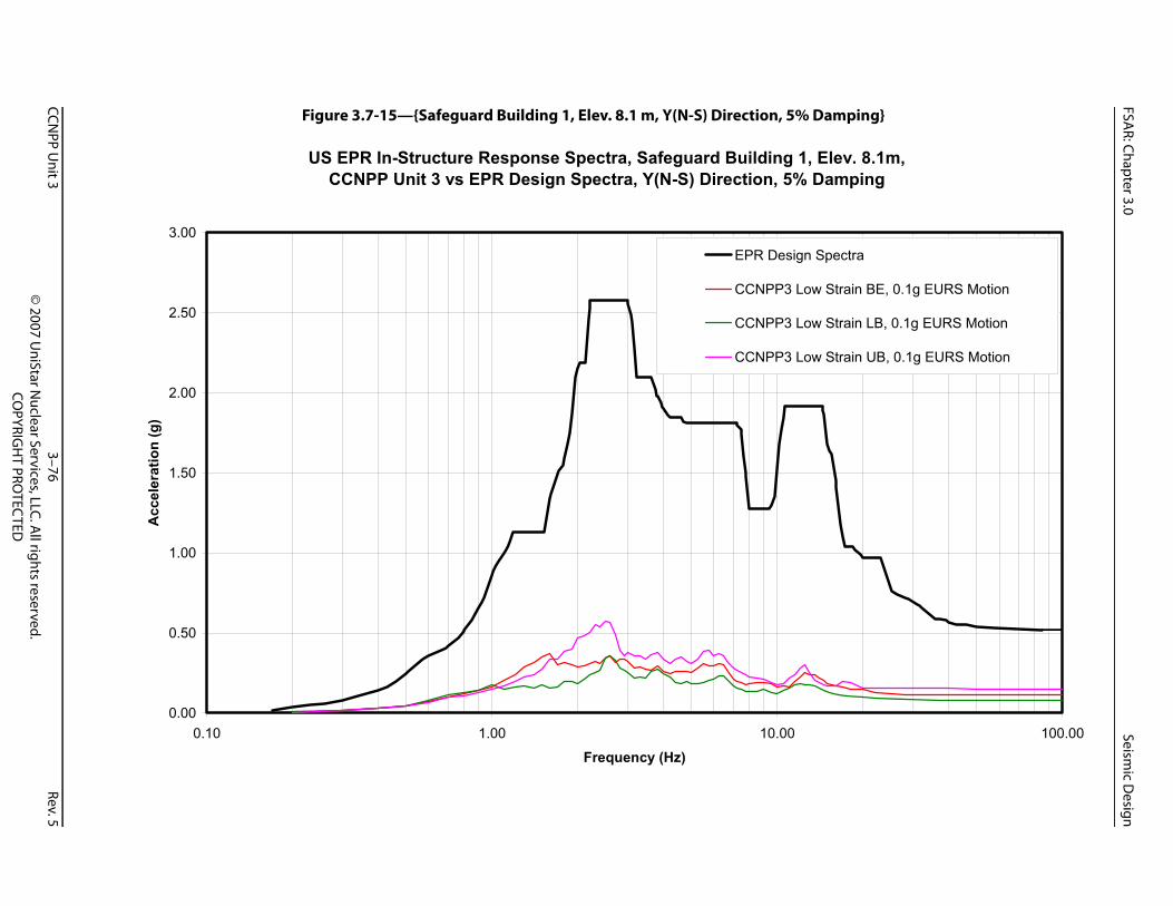
FSAR: Chapter 3.0
Seismic D
esign
CCNPP U
nit 33–76
Rev.5©
2007 UniStar N
uclear Services, LLC. All rights reserved.
COPYRIG
HT PRO
TECTED
ping}
v. 8.1m,ping
100.00
ctra
ain BE, 0.1g EURS Motion
ain LB, 0.1g EURS Motion
ain UB, 0.1g EURS Motion
Figure 3.7-15—{Safeguard Building 1, Elev. 8.1 m, Y(N-S) Direction, 5% Dam
US EPR In-Structure Response Spectra, Safeguard Building 1, EleCCNPP Unit 3 vs EPR Design Spectra, Y(N-S) Direction, 5% Dam
0.00
0.50
1.00
1.50
2.00
2.50
3.00
0.10 1.00 10.00
Frequency (Hz)
Acc
eler
atio
n (g
)
EPR Design Spe
CCNPP3 Low Str
CCNPP3 Low Str
CCNPP3 Low Str

FSAR: Chapter 3.0
Seismic D
esign
CCNPP U
nit 33–77
Rev.5©
2007 UniStar N
uclear Services, LLC. All rights reserved.
COPYRIG
HT PRO
TECTED
ping}
v. 8.1m,ping
100.00
Figure 3.7-16—{Safeguard Building 1, Elev. 8.1 m, Z(Vert) Direction, 5% Dam
US EPR In-Structure Response Spectra, Safeguard Building 1, EleCCNPP Unit 3 vs EPR Design Spectra, Z(Vert) Direction, 5% Dam
0.00
0.50
1.00
1.50
2.00
2.50
3.00
3.50
0.10 1.00 10.00
Frequency (Hz)
Acc
eler
atio
n (g
)
EPR Design Spectra
CCNPP3 Low Strain BE, 0.1g EURS Motion
CCNPP3 Low Strain LB, 0.1g EURS Motion
CCNPP3 Low Strain UB, 0.1g EURS Motion

FSAR: Chapter 3.0
Seismic D
esign
CCNPP U
nit 33–78
Rev.5©
2007 UniStar N
uclear Services, LLC. All rights reserved.
COPYRIG
HT PRO
TECTED
ping}
. 21.0m,ping
100.00
Figure 3.7-17—{Safeguard Building 1, Elev. 21.0 m, X(E-W) Direction, 5% Dam
US EPR In-Structure Response Spectra, Safeguard Building 1, ElevCCNPP Unit 3 vs EPR Design Spectra, X(E-W) Direction, 5% Dam
0.00
0.50
1.00
1.50
2.00
2.50
3.00
3.50
4.00
0.10 1.00 10.00
Frequency (Hz)
Acc
eler
atio
n (g
)
EPR Design Spectra
CCNPP3 Low Strain BE, 0.1g EURS Motion
CCNPP3 Low Strain LB, 0.1g EURS Motion
CCNPP3 Low Strain UB, 0.1g EURS Motion

FSAR: Chapter 3.0
Seismic D
esign
CCNPP U
nit 33–79
Rev.5©
2007 UniStar N
uclear Services, LLC. All rights reserved.
COPYRIG
HT PRO
TECTED
ping}
. 21.0m,ping
100.00
Figure 3.7-18—{Safeguard Building 1, Elev. 21.0 m, Y(N-S) Direction, 5% Dam
US EPR In-Structure Response Spectra, Safeguard Building 1, ElevCCNPP Unit 3 vs EPR Design Spectra, Y(N-S) Direction, 5% Dam
0.00
0.50
1.00
1.50
2.00
2.50
3.00
3.50
4.00
0.10 1.00 10.00
Frequency (Hz)
Acc
eler
atio
n (g
)
EPR Design Spectra
CCNPP3 Low Strain BE, 0.1g EURS Motion
CCNPP3 Low Strain LB, 0.1g EURS Motion
CCNPP3 Low Strain UB, 0.1g EURS Motion

FSAR: Chapter 3.0
Seismic D
esign
CCNPP U
nit 33–80
Rev.5©
2007 UniStar N
uclear Services, LLC. All rights reserved.
COPYRIG
HT PRO
TECTED
ping}
. 21.0m,ping
100.00
Figure 3.7-19—{Safeguard Building 1, Elev. 21.0 m, Z(Vert) Direction, 5% Dam
US EPR In-Structure Response Spectra, Safeguard Building 1, ElevCCNPP Unit 3 vs EPR Design Spectra, Z(Vert) Direction, 5% Dam
0.00
0.50
1.00
1.50
2.00
2.50
3.00
3.50
4.00
4.50
5.00
0.10 1.00 10.00
Frequency (Hz)
Acc
eler
atio
n (g
)
EPR Design Spectra
CCNPP3 Low Strain BE, 0.1g EURS Motion
CCNPP3 Low Strain LB, 0.1g EURS Motion
CCNPP3 Low Strain UB, 0.1g EURS Motion

FSAR: Chapter 3.0
Seismic D
esign
CCNPP U
nit 33–81
Rev.5©
2007 UniStar N
uclear Services, LLC. All rights reserved.
COPYRIG
HT PRO
TECTED
mping}
ev. 8.1m,ping
100.00
Figure 3.7-20—{Safeguard Building 2/3, Elev. 8.1 m, X(E-W) Direction, 5% Da
US EPR In-Structure Response Spectra, Safeguard Building 2/3, ElCCNPP Unit 3 vs EPR Design Spectra, X(E-W) Direction, 5% Dam
0.00
0.50
1.00
1.50
2.00
2.50
3.00
3.50
0.10 1.00 10.00
Frequency (Hz)
Acc
eler
atio
n (g
)
EPR Design Spectra
CCNPP3 Low Strain BE, 0.1g EURS Motion
CCNPP3 Low Strain LB, 0.1g EURS Motion
CCNPP3 Low Strain UB, 0.1g EURS Motion

FSAR: Chapter 3.0
Seismic D
esign
CCNPP U
nit 33–82
Rev.5©
2007 UniStar N
uclear Services, LLC. All rights reserved.
COPYRIG
HT PRO
TECTED
ping}
ev. 8.1m,ping
100.00
Figure 3.7-21—{Safeguard Building 2/3, Elev. 8.1 m, Y(N-S) Direction, 5% Dam
US EPR In-Structure Response Spectra, Safeguard Building 2/3, ElCCNPP Unit 3 vs EPR Design Spectra, Y(N-S) Direction, 5% Dam
0.00
0.50
1.00
1.50
2.00
2.50
3.00
0.10 1.00 10.00
Frequency (Hz)
Acc
eler
atio
n (g
)
EPR Design Spectra
CCNPP3 Low Strain BE, 0.1g EURS Motion
CCNPP3 Low Strain LB, 0.1g EURS Motion
CCNPP3 Low Strain UB, 0.1g EURS Motion

FSAR: Chapter 3.0
Seismic D
esign
CCNPP U
nit 33–83
Rev.5©
2007 UniStar N
uclear Services, LLC. All rights reserved.
COPYRIG
HT PRO
TECTED
mping}
ev. 8.1m,ping
100.00
Figure 3.7-22—{Safeguard Building 2/3, Elev. 8.1 m, Z(Vert) Direction, 5% Da
US EPR In-Structure Response Spectra, Safeguard Building 2/3, ElCCNPP Unit 3 vs EPR Design Spectra, Z(Vert) Direction, 5% Dam
0.00
0.50
1.00
1.50
2.00
2.50
3.00
3.50
0.10 1.00 10.00
Frequency (Hz)
Acc
eler
atio
n (g
)
EPR Design Spectra
CCNPP3 Low Strain BE, 0.1g EURS Motion
CCNPP3 Low Strain LB, 0.1g EURS Motion
CCNPP3 Low Strain UB, 0.1g EURS Motion

FSAR: Chapter 3.0
Seismic D
esign
CCNPP U
nit 33–84
Rev.5©
2007 UniStar N
uclear Services, LLC. All rights reserved.
COPYRIG
HT PRO
TECTED
mping}
v. 15.4m,ping
100.00
Figure 3.7-23—{Safeguard Building 2/3, Elev. 15.4 m, X(E-W) Direction, 5% Da
US EPR In-Structure Response Spectra, Safeguard Building 2/3, EleCCNPP Unit 3 vs EPR Design Spectra, X(E-W) Direction, 5% Dam
0.00
0.50
1.00
1.50
2.00
2.50
3.00
3.50
4.00
4.50
5.00
0.10 1.00 10.00
Frequency (Hz)
Acc
eler
atio
n (g
)
EPR Design Spectra
CCNPP3 Low Strain BE, 0.1g EURS Motion
CCNPP3 Low Strain LB, 0.1g EURS Motion
CCNPP3 Low Strain UB, 0.1g EURS Motion

FSAR: Chapter 3.0
Seismic D
esign
CCNPP U
nit 33–85
Rev.5©
2007 UniStar N
uclear Services, LLC. All rights reserved.
COPYRIG
HT PRO
TECTED
mping}
v. 15.4m,ping
100.00
Figure 3.7-24—{Safeguard Building 2/3, Elev. 15.4 m, Y(N-S) Direction, 5% Da
US EPR In-Structure Response Spectra, Safeguard Building 2/3, EleCCNPP Unit 3 vs EPR Design Spectra, Y(N-S) Direction, 5% Dam
0.00
0.50
1.00
1.50
2.00
2.50
3.00
3.50
4.00
0.10 1.00 10.00
Frequency (Hz)
Acc
eler
atio
n (g
)
EPR Design Spectra
CCNPP3 Low Strain BE, 0.1g EURS Motion
CCNPP3 Low Strain LB, 0.1g EURS Motion
CCNPP3 Low Strain UB, 0.1g EURS Motion
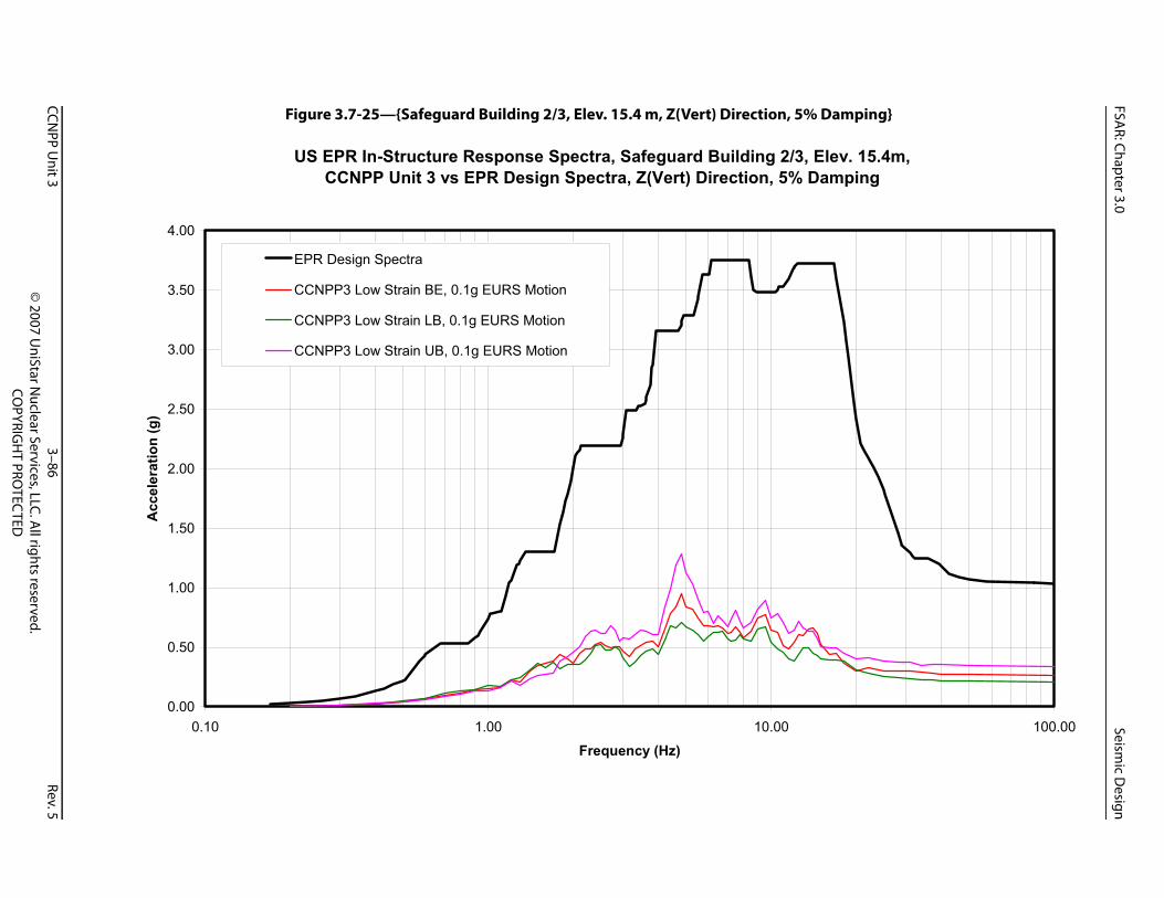
FSAR: Chapter 3.0
Seismic D
esign
CCNPP U
nit 33–86
Rev.5©
2007 UniStar N
uclear Services, LLC. All rights reserved.
COPYRIG
HT PRO
TECTED
mping}
v. 15.4m,ping
100.00
Figure 3.7-25—{Safeguard Building 2/3, Elev. 15.4 m, Z(Vert) Direction, 5% Da
US EPR In-Structure Response Spectra, Safeguard Building 2/3, EleCCNPP Unit 3 vs EPR Design Spectra, Z(Vert) Direction, 5% Dam
0.00
0.50
1.00
1.50
2.00
2.50
3.00
3.50
4.00
0.10 1.00 10.00
Frequency (Hz)
Acc
eler
atio
n (g
)
EPR Design Spectra
CCNPP3 Low Strain BE, 0.1g EURS Motion
CCNPP3 Low Strain LB, 0.1g EURS Motion
CCNPP3 Low Strain UB, 0.1g EURS Motion
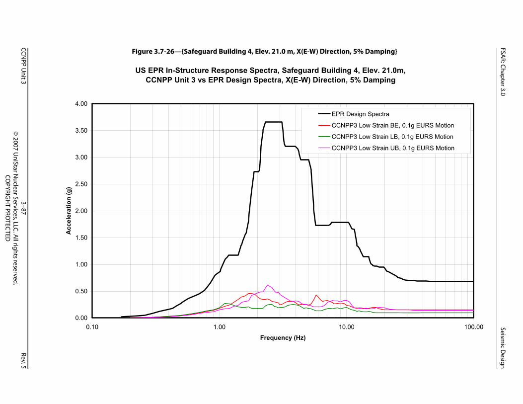
FSAR: Chapter 3.0
Seismic D
esign
CCNPP U
nit 33–87
Rev.5©
2007 UniStar N
uclear Services, LLC. All rights reserved.
COPYRIG
HT PRO
TECTED
ping}
. 21.0m,ping
100.00
ectra
train BE, 0.1g EURS Motion
train LB, 0.1g EURS Motion
train UB, 0.1g EURS Motion
Figure 3.7-26—{Safeguard Building 4, Elev. 21.0 m, X(E-W) Direction, 5% Dam
US EPR In-Structure Response Spectra, Safeguard Building 4, ElevCCNPP Unit 3 vs EPR Design Spectra, X(E-W) Direction, 5% Dam
0.00
0.50
1.00
1.50
2.00
2.50
3.00
3.50
4.00
0.10 1.00 10.00
Frequency (Hz)
Acc
eler
atio
n (g
)
EPR Design Sp
CCNPP3 Low S
CCNPP3 Low S
CCNPP3 Low S
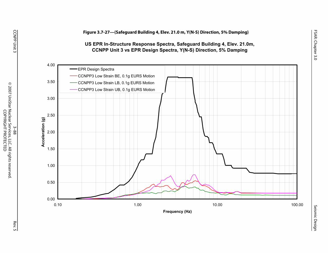
FSAR: Chapter 3.0
Seismic D
esign
CCNPP U
nit 33–88
Rev.5©
2007 UniStar N
uclear Services, LLC. All rights reserved.
COPYRIG
HT PRO
TECTED
ping}
. 21.0m,ping
100.00
Figure 3.7-27—{Safeguard Building 4, Elev. 21.0 m, Y(N-S) Direction, 5% Dam
US EPR In-Structure Response Spectra, Safeguard Building 4, ElevCCNPP Unit 3 vs EPR Design Spectra, Y(N-S) Direction, 5% Dam
0.00
0.50
1.00
1.50
2.00
2.50
3.00
3.50
4.00
0.10 1.00 10.00
Frequency (Hz)
Acc
eler
atio
n (g
)
EPR Design Spectra
CCNPP3 Low Strain BE, 0.1g EURS Motion
CCNPP3 Low Strain LB, 0.1g EURS Motion
CCNPP3 Low Strain UB, 0.1g EURS Motion
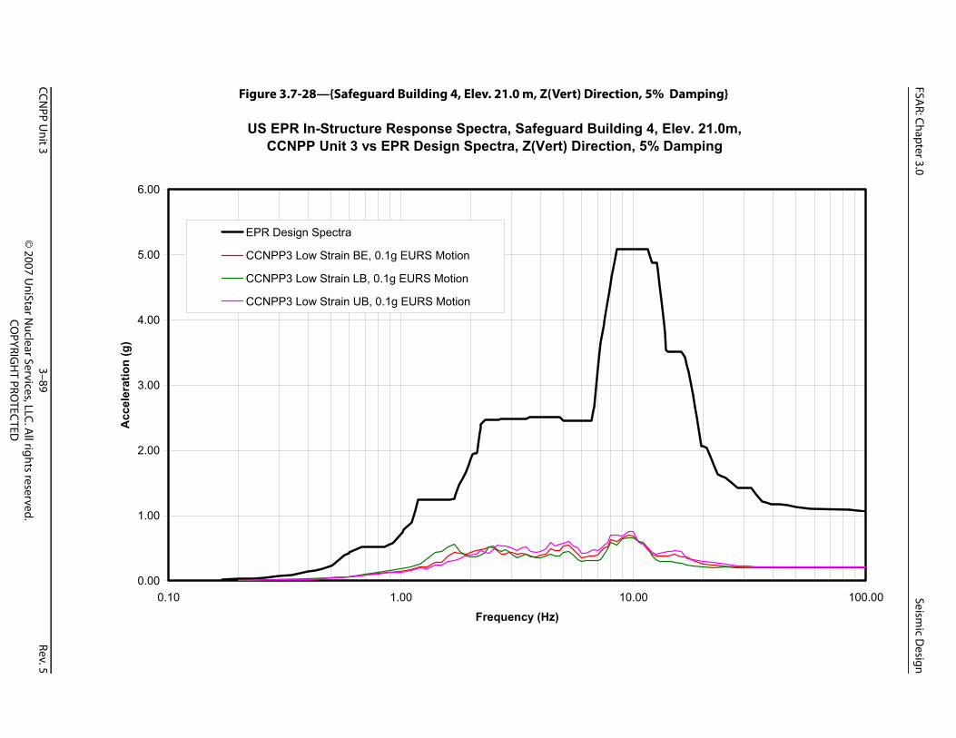
FSAR: Chapter 3.0
Seismic D
esign
CCNPP U
nit 33–89
Rev.5©
2007 UniStar N
uclear Services, LLC. All rights reserved.
COPYRIG
HT PRO
TECTED
mping}
. 21.0m,ping
100.00
Figure 3.7-28—{Safeguard Building 4, Elev. 21.0 m, Z(Vert) Direction, 5% Da
US EPR In-Structure Response Spectra, Safeguard Building 4, ElevCCNPP Unit 3 vs EPR Design Spectra, Z(Vert) Direction, 5% Dam
0.00
1.00
2.00
3.00
4.00
5.00
6.00
0.10 1.00 10.00
Frequency (Hz)
Acc
eler
atio
n (g
)
EPR Design Spectra
CCNPP3 Low Strain BE, 0.1g EURS Motion
CCNPP3 Low Strain LB, 0.1g EURS Motion
CCNPP3 Low Strain UB, 0.1g EURS Motion
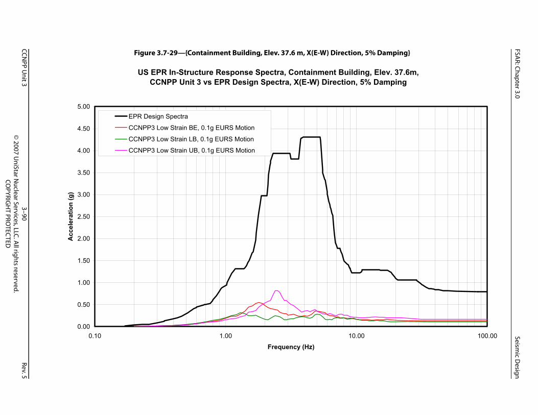
FSAR: Chapter 3.0
Seismic D
esign
CCNPP U
nit 33–90
Rev.5©
2007 UniStar N
uclear Services, LLC. All rights reserved.
COPYRIG
HT PRO
TECTED
mping}
v. 37.6m,ping
100.00
Figure 3.7-29—{Containment Building, Elev. 37.6 m, X(E-W) Direction, 5% Da
US EPR In-Structure Response Spectra, Containment Building, EleCCNPP Unit 3 vs EPR Design Spectra, X(E-W) Direction, 5% Dam
0.00
0.50
1.00
1.50
2.00
2.50
3.00
3.50
4.00
4.50
5.00
0.10 1.00 10.00
Frequency (Hz)
Acc
eler
atio
n (g
)
EPR Design Spectra
CCNPP3 Low Strain BE, 0.1g EURS Motion
CCNPP3 Low Strain LB, 0.1g EURS Motion
CCNPP3 Low Strain UB, 0.1g EURS Motion
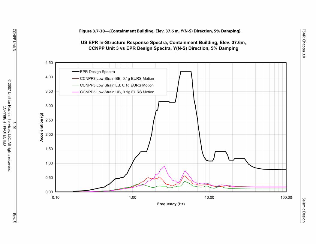
FSAR: Chapter 3.0
Seismic D
esign
CCNPP U
nit 33–91
Rev.5©
2007 UniStar N
uclear Services, LLC. All rights reserved.
COPYRIG
HT PRO
TECTED
mping}
v. 37.6m,ping
100.00
Figure 3.7-30—{Containment Building, Elev. 37.6 m, Y(N-S) Direction, 5% Da
US EPR In-Structure Response Spectra, Containment Building, EleCCNPP Unit 3 vs EPR Design Spectra, Y(N-S) Direction, 5% Dam
0.00
0.50
1.00
1.50
2.00
2.50
3.00
3.50
4.00
4.50
0.10 1.00 10.00
Frequency (Hz)
Acc
eler
atio
n (g
)
EPR Design Spectra
CCNPP3 Low Strain BE, 0.1g EURS Motion
CCNPP3 Low Strain LB, 0.1g EURS Motion
CCNPP3 Low Strain UB, 0.1g EURS Motion
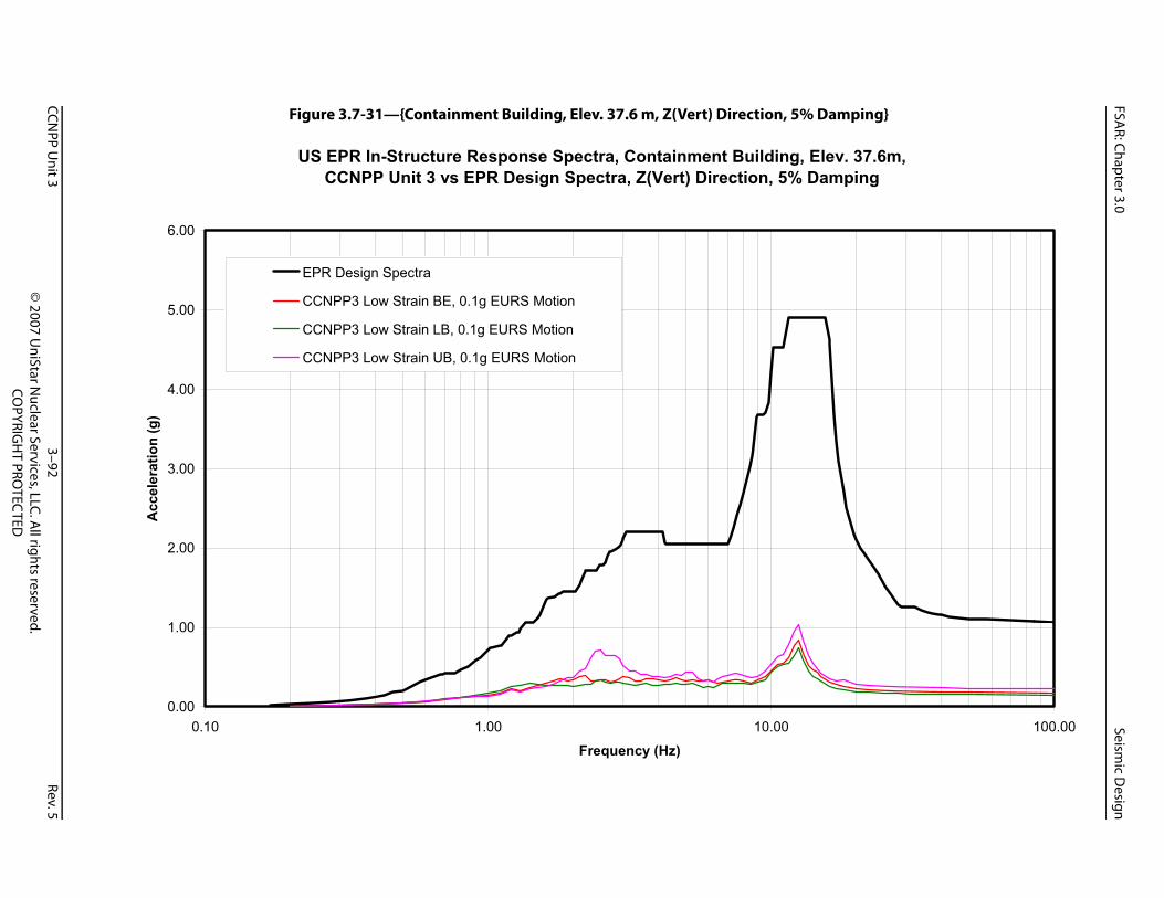
FSAR: Chapter 3.0
Seismic D
esign
CCNPP U
nit 33–92
Rev.5©
2007 UniStar N
uclear Services, LLC. All rights reserved.
COPYRIG
HT PRO
TECTED
mping}
v. 37.6m,ping
100.00
Figure 3.7-31—{Containment Building, Elev. 37.6 m, Z(Vert) Direction, 5% Da
US EPR In-Structure Response Spectra, Containment Building, EleCCNPP Unit 3 vs EPR Design Spectra, Z(Vert) Direction, 5% Dam
0.00
1.00
2.00
3.00
4.00
5.00
6.00
0.10 1.00 10.00
Frequency (Hz)
Acc
eler
atio
n (g
)
EPR Design Spectra
CCNPP3 Low Strain BE, 0.1g EURS Motion
CCNPP3 Low Strain LB, 0.1g EURS Motion
CCNPP3 Low Strain UB, 0.1g EURS Motion

FSAR: Chapter 3.0
Seismic D
esign
CCNPP U
nit 33–93
Rev.5©
2007 UniStar N
uclear Services, LLC. All rights reserved.
COPYRIG
HT PRO
TECTED
mping}
v. 58.0m,ping
100.00
Figure 3.7-32—{Containment Building, Elev. 58.0 m, X(E-W) Direction, 5% Da
US EPR In-Structure Response Spectra, Containment Building, EleCCNPP Unit 3 vs EPR Design Spectra, X(E-W) Direction, 5% Dam
0.00
1.00
2.00
3.00
4.00
5.00
6.00
7.00
8.00
0.10 1.00 10.00
Frequency (Hz)
Acc
eler
atio
n (g
)
EPR Design Spectra
CCNPP3 Low Strain BE, 0.1g EURS Motion
CCNPP3 Low Strain LB, 0.1g EURS Motion
CCNPP3 Low Strain UB, 0.1g EURS Motion

FSAR: Chapter 3.0
Seismic D
esign
CCNPP U
nit 33–94
Rev.5©
2007 UniStar N
uclear Services, LLC. All rights reserved.
COPYRIG
HT PRO
TECTED
mping}
v. 58.0m,ping
100.00
Figure 3.7-33—{Containment Building, Elev. 58.0 m, Y(N-S) Direction, 5% Da
US EPR In-Structure Response Spectra, Containment Building, EleCCNPP Unit 3 vs EPR Design Spectra, Y(N-S) Direction, 5% Dam
0.00
1.00
2.00
3.00
4.00
5.00
6.00
7.00
0.10 1.00 10.00
Frequency (Hz)
Acc
eler
atio
n (g
)
EPR Design Spectra
CCNPP3 Low Strain BE, 0.1g EURS Motion
CCNPP3 Low Strain LB, 0.1g EURS Motion
CCNPP3 Low Strain UB, 0.1g EURS Motion

FSAR: Chapter 3.0
Seismic D
esign
CCNPP U
nit 33–95
Rev.5©
2007 UniStar N
uclear Services, LLC. All rights reserved.
COPYRIG
HT PRO
TECTED
mping}
v. 58.0m,ping
100.00
Figure 3.7-34—{Containment Building, Elev. 58.0 m, Z(Vert) Direction, 5% Da
US EPR In-Structure Response Spectra, Containment Building, EleCCNPP Unit 3 vs EPR Design Spectra, Z(Vert) Direction, 5% Dam
0.00
2.00
4.00
6.00
8.00
10.00
12.00
14.00
16.00
18.00
0.10 1.00 10.00
Frequency (Hz)
Acc
eler
atio
n (g
)
EPR Design Spectra
CCNPP3 Low Strain BE, 0.1g EURS Motion
CCNPP3 Low Strain LB, 0.1g EURS Motion
CCNPP3 Low Strain UB, 0.1g EURS Motion

FSAR: Chapter 3.0
Seismic D
esign
CCNPP U
nit 33–96
Rev.5©
2007 UniStar N
uclear Services, LLC. All rights reserved.
COPYRIG
HT PRO
TECTED
rgency Power Generating
EUR Soft Site CSDRS
EUR Medium Site CSDRS
EUR Hard Site CSDRS
Site-Specif ic FIRS
Figure 3.7-35—{Comparison of Horizontal Ground Response Spectra (5% Damping) for the EmeBuildings and the Essential Service Water Buildings}
0.0
0.1
0.2
0.3
0.4
0.5
0.6
0.7
0.8
0.9
1.0
0.1 1.0 10.0 100.0
Frequency (Hz)
Acce
lera
tion
(g)

FSAR: Chapter 3.0
Seismic D
esign
CCNPP U
nit 33–97
Rev.5©
2007 UniStar N
uclear Services, LLC. All rights reserved.
COPYRIG
HT PRO
TECTED
Power Generating Buildings
EUR Soft Site CSDRS
EUR Medium Site CSDRS
EUR Hard Site CSDRS
Site-Specif ic FIRS
Figure 3.7-36—{Comparison of Vertical Ground Response Spectra (5% Damping) for the Emergencyand the Essential Service Water Buildings}
0.0
0.1
0.2
0.3
0.4
0.5
0.6
0.7
0.8
0.9
1.0
0.1 1.0 10.0 100.0
Frequency (Hz)
Acce
lera
tion
(g)
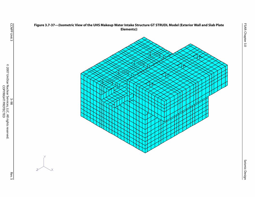
FSAR: Chapter 3.0
Seismic D
esign
CCNPP U
nit 33–98
Rev.5©
2007 UniStar N
uclear Services, LLC. All rights reserved.
COPYRIG
HT PRO
TECTED
terior Wall and Slab Plate
Figure 3.7-37—{Isometric View of the UHS Makeup Water Intake Structure GT STRUDL Model (ExElements)}X
Y
Z

FSAR: Chapter 3.0
Seismic D
esign
CCNPP U
nit 33–99
Rev.5©
2007 UniStar N
uclear Services, LLC. All rights reserved.
COPYRIG
HT PRO
TECTED
ater Intake Structure)}
100.0
Figure 3.7-38—{Comparison of Ground Response Spectra, 5% Damping for the UHS Makeup W
0.00
0.05
0.10
0.15
0.20
0.25
0.30
0.35
0.40
0.45
0.50
0.1 1.0 10.0
Site-Specific Horizontal GMRS
RG 1.60 Horizontal Spectrum EUR Soft Site Spectrum
Frequency (Hz)
Acce
lera
tion
(g)

FSAR: Chapter 3.0
Seismic D
esign
CCNPP U
nit 33–100
Rev.5©
2007 UniStar N
uclear Services, LLC. All rights reserved.
COPYRIG
HT PRO
TECTED
in MD East-West CCNPP Plant
100.0
1% Damp2% Damp3% Damp5% Damp7% Damp10% Damp
Figure 3.7-39—{Broadened ISRS for UHS Makeup Water Intake Structure, Elevation 11.5 ft (3.51 m) North-South (X) Direction}
0.0
0.5
1.0
1.5
2.0
2.5
3.0
3.5
4.0
4.5
0.1 1.0 10.0Frequency (Hz)
Acce
lera
tion
(g)

FSAR: Chapter 3.0
Seismic D
esign
CCNPP U
nit 33–101
Rev.5©
2007 UniStar N
uclear Services, LLC. All rights reserved.
COPYRIG
HT PRO
TECTED
) in MD North-South CCNPP
100.0
% Damp% Damp% Damp% Damp% Damp0% Damp
Figure 3.7-40—{Broadened ISRS for UHS Makeup Water Intake Structure, Elevation 11.5 ft (3.51 mPlant East-West (Z) Direction}
0.0
0.5
1.0
1.5
2.0
2.5
3.0
3.5
4.0
4.5
5.0
0.1 1.0 10.0Frequency (Hz)
Acc
eler
atio
n (g
)
123571
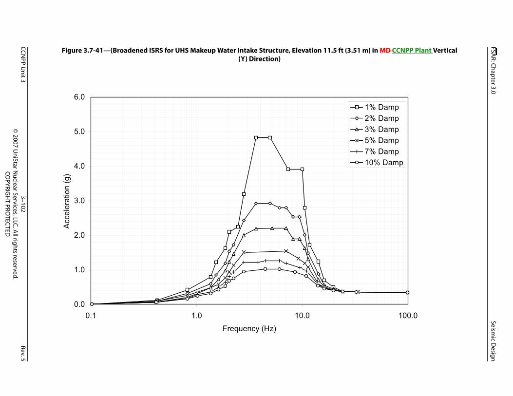
FSAR: Chapter 3.0
Seismic D
esign
CCNPP U
nit 33–102
Rev.5©
2007 UniStar N
uclear Services, LLC. All rights reserved.
COPYRIG
HT PRO
TECTED
) in MD CCNPP Plant Vertical
100.0
% Damp% Damp% Damp% Damp% Damp0% Damp
Figure 3.7-41—{Broadened ISRS for UHS Makeup Water Intake Structure, Elevation 11.5 ft (3.51 m(Y) Direction}
0.0
1.0
2.0
3.0
4.0
5.0
6.0
0.1 1.0 10.0Frequency (Hz)
Acc
eler
atio
n (g
)
123571

FSAR: Chapter 3.0 Design of Category I Structures
3.8 DESIGN OF CATEGORY I STRUCTURES
This section of the U.S. EPR FSAR is incorporated by reference with the departures and supplements as described in the following sections.
3.8.1 CONCRETE CONTAINMENT
No departures or supplements.
3.8.1.1 Description of the Containment
No departures or supplements.
3.8.1.2 Applicable Codes, Standards, and Specifications
No departures or supplements.
3.8.1.3 Loads and Load Combinations
The U.S. EPR FSAR includes the following COL Item in Section 3.8.1.3:
A COL applicant that references the U.S. EPR design certification will confirm that site-specific loads lie within the standard plant design envelope for the RCB, or perform additional analyses to verify structural adequacy.
This COL Item is addressed as follows:
{The RCB design for CCNPP Unit 3 is the standard RCB design as described in the U.S. EPR FSAR without departures. Site-specific loads are confirmed to lie within the standard U.S. EPR design certification envelope. Relative site-specific seismic, RSB, and buoyancy conditions are addressed in Sections 3.7.2, 3.8.4, and 3.8.5, respectively.}
3.8.1.4 Design and Analysis Procedures
No departures or supplements.
3.8.1.5 Structural Acceptance Criteria
No departures or supplements.
3.8.1.6 Materials, Quality Control, and Special Construction Techniques
No departures or supplements.
3.8.1.6.1 Concrete Materials
No departures or supplements.
3.8.1.6.2 Reinforcing Steel and Splice Materials
No departures or supplements.
3.8.1.6.3 Tendon System Materials
No departures or supplements.
CCNPP Unit 3 3–103 Rev. 5© 2007 UniStar Nuclear Services, LLC. All rights reserved.
COPYRIGHT PROTECTED

FSAR: Chapter 3.0 Design of Category I Structures
3.8.1.6.4 Liner Plate System and Penetration Sleeve Materials
No departures or supplements.
3.8.1.6.5 Steel Embedments
No departures or supplements.
3.8.1.6.6 Corrosion Retarding Compounds
No departures or supplements.
3.8.1.6.7 Quality Control
The QA program for this section is discussed in Section 3.1.1.1.1.
3.8.1.6.8 Special Construction Techniques
No departures or supplements.
3.8.1.7 Testing and Inservice Inspection Requirements
No departures or supplements.
3.8.2 STEEL CONTAINMENT
No departures or supplements.
3.8.3 CONCRETE AND STEEL INTERNAL STRUCTURES OF CONCRETE CONTAINMENT
3.8.3.1 Description of the Internal Structures
No departures or supplements.
3.8.3.2 Applicable Codes, Standards, and Specifications
No departures or supplements.
3.8.3.3 Loads and Load Combinations
The U.S. EPR FSAR includes the following COL Item in Section 3.8.3.3:
A COL applicant that references the U.S. EPR design certification will confirm that site-specific loads lie within the standard design envelope for RB internal structures, or perform additional analyses to verify structural adequacy.
This COL Item is addressed as follows:
{The Reactor Building (RB) (i.e., the Reactor Containment Building (RCB)) internal structural design is the standard design as described in the U.S. EPR FSAR without departures. Site-specific loads are confirmed to lie within the standard U.S. EPR design certification envelope. Relative site-specific conditions are addressed in Section 3.7.2.}
3.8.3.4 Design and Analysis Procedures
No departures or supplements.
CCNPP Unit 3 3–104 Rev. 5© 2007 UniStar Nuclear Services, LLC. All rights reserved.
COPYRIGHT PROTECTED

FSAR: Chapter 3.0 Design of Category I Structures
3.8.3.5 Structural Acceptance Criteria
No departures or supplements.
3.8.3.6 Materials, Quality Control, and Special Construction Techniques
No departures or supplements.
3.8.3.7 Testing and Inservice Inspection Requirements
No departures or supplements.
3.8.4 OTHER SEISMIC CATEGORY I STRUCTURES
3.8.4.1 Description of the Structures
The U.S. EPR FSAR includes the following COL Items in Section 3.8.4:
A COL applicant that references the U.S. EPR design certification will describe any differences between the standard plant layout and design of Seismic Category I structures required for site-specific conditions.
A COL applicant that references the U.S. EPR design certification will address site-specific Seismic Category I structures that are not described in this section.
The COL Items are addressed as follows:
{The site-specific Seismic Category I structures at CCNPP Unit 3 are:
Buried Conduit and Duct banks (Section 3.8.4.1.8).
Buried Pipe and Pipe Ducts (Section 3.8.4.1.9).
UHS Makeup Water Intake Structure and UHS Electrical Building (Section 3.8.4.1.11).}
3.8.4.1.1 Reactor Shield Building and Annulus
No departures or supplements.
3.8.4.1.2 Fuel Building
No departures or supplements.
3.8.4.1.3 Safeguard Buildings
No departures or supplements.
3.8.4.1.4 Emergency Power Generating Buildings
No departures or supplements.
3.8.4.1.5 Essential Service Water Buildings
No departures or supplements.
CCNPP Unit 3 3–105 Rev. 5© 2007 UniStar Nuclear Services, LLC. All rights reserved.
COPYRIGHT PROTECTED

FSAR: Chapter 3.0 Design of Category I Structures
3.8.4.1.6 Distribution System Supports
No departures or supplements.
3.8.4.1.7 Platforms and Miscellaneous Structures
No departures or supplements.
3.8.4.1.8 Buried Conduit and Duct Banks
The U.S. EPR FSAR includes the following COL Item and conceptual design information in Section 3.8.4.1.8:
A COL applicant that references the U.S. EPR design certification will provide a description of Seismic Category I buried conduit and duct banks.
[[Buried conduits are steel while conduits in encased duct banks may be poly-vinyl-chloride (PVC) or steel. Duct banks may be directly buried in the soil; encased in lean concrete, concrete, or reinforced concrete. Concrete or reinforced concrete encased duct banks will be used in heavy haul zones, under roadway crossings, or where seismic effects dictate the requirement. Encasement in lean concrete may be used in areas not subject to trenching or passage of heavy haul equipment, or where seismic effects on the conduit are not significant.]]
{This COL Item is addressed as follows, and the conceptual design information is replaced with site-specific information for CCNPP Unit 3:
Figure 3.8-1 provides an overall site plan of Seismic Category I buried duct banks. The buried duct banks run between the NI and the Intake Structures along the utility corridor. Figure 3.8-2 provides a detail plan of Seismic Category I buried duct banks in the vicinity of the NI. No Seismic Category I buried conduits exist for CCNPP Unit 3.
Seismic Category I buried electrical duct banks traverse from:
The UHS Makeup Water Intake Structure to the UHS Electrical Building.
Each Essential Service Water Building to the UHS Electrical Building, including underneath the main heavy haul road.
The Safeguards Buildings to the four Essential Service Water Buildings and both Emergency Power Generating Buildings.
For the first item, the UHS Makeup Water Intake Structure and UHS Electrical Buildings are discrete structures housing mechanical and electrical equipment, respectively. Buried electrical duct banks traverse the two structures to provide power to the equipment, including the UHS Makeup Water pumps.
Buried electrical duct banks consist of polyvinyl chloride (PVC) conduit encased in reinforced concrete. In addition to its structural function, the reinforced concrete facilitates maintenance of conduit spacing / separation requirements and protects the conduit.
Where buried safety-related electrical duct banks share a common route with and the ESW pipe UHS makeup water pipes traversing the UHS Makeup Water Intake Structure and the four ESWBs need to be above each other, the buried electrical duct banks are located below the
CCNPP Unit 3 3–106 Rev. 5© 2007 UniStar Nuclear Services, LLC. All rights reserved.
COPYRIGHT PROTECTED

FSAR: Chapter 3.0 Design of Category I Structures
pipes to facilitate future pipe maintenance. To facilitate cable pulling and routing, electrical manholes are provided at strategic locations.}
3.8.4.1.9 Buried Pipe and Pipe Ducts
The U.S. EPR FSAR includes the following COL Item in Section 3.8.4.1.9:
A COL applicant that references the U.S. EPR design certification will provide a description of Seismic Category I buried pipe and pipe ductsducts.
This COL Item is addressed as follows:
{Figure 3.8-3 provides an overall site plan of Seismic Category I buried pipe. Pipes run beneath the final site grade. Buried pipe ducts are not used for CCNPP Unit 3. Two buried Unit 3 Intake Pipes run from the CCNPP Unit 3 Inlet Area to the Unit 3 Forebay (See Fig. 2.4-51). The four ESW Four UHS Makeup Water pipes emanate from the UHS Makeup Water Intake Structure and terminate at the ESWBs. These pipes run within the utility corridor, shown in Figure 3.8.3, and pass under the main heavy haul road Haul Road which runs in the East-West direction adjacent to the North side of the CCNPP Unit 3 power block.
Figure 3.8-4 provides a detail plan of Seismic Category I buried ESW UHS Makeup Water pipe in the vicinity of the NI. As illustrated in the figure, the Seismic Category I buried ESW UHS Makeup Water piping consists of:
Large diameter supply and return pipes between the Safeguards Buildings and the ESWBs.
Small Large diameter supply and return pipes from the EPGBs which tie in directly to the aforementioned pipes.
Fire Protection pipe traverses from the UHS Makeup Water Intake Structure and UHS Electrical Building to the vicinity of the NI, where a loop is provided to all buildings. In accordance with Section 3.2.2., Fire Protection pipe piping to Seismic Category I structures that is classified as: 1) Seismic Category II is designed to maintain its pressure boundary after an SSE event; and 2) Seismic Category II-SSE is designed to remain functional following an SSE event.
The buried piping is directly buried in the soil (i.e., without concrete encasement) unless detailed analysis indicates that additional protection is required. The depth of the cover is of sufficient depth to provide protection against frost, surcharge effects, and tornado missiles. Bedding material is provided underneath the pipe or as an alternate, lean concrete may be used. Soil surrounding the pipe is typically compacted structural backfill. As an alternate, lean concrete may be used.}
3.8.4.1.10 Masonry Walls
{No departures or supplements.}
3.8.4.1.11 {UHS Makeup Water Intake Structure and UHS Electrical Building}
{This section is added as a supplement to U.S. EPR FSAR Section 3.8.4.1.
The Seismic Category I UHS Makeup Water Intake Structure and Seismic Category I UHS Electrical Building are situated along the western shoreline of the Chesapeake Bay. Both structures house components associated with the UHS Makeup Water System, which provides
CCNPP Unit 3 3–107 Rev. 5© 2007 UniStar Nuclear Services, LLC. All rights reserved.
COPYRIGHT PROTECTED

FSAR: Chapter 3.0 Design of Category I Structures
emergency makeup water to the Essential Service Water Cooling Tower basins for the shutdown of the plant, following 72 hours after a design basis accident. Figure 2.1-1 provides a site plan for the CCNPP Unit 3, which shows the position of the UHS Makeup Water Intake Structure and UHS Electrical Building relative to the NI.
As illustrated in Figures 9.2-4, 9.2-5, and 9.2-6, the UHS Makeup Water Intake Structure is 75 ft (22.9 m) long overall by 60 ft (18.3 m) wide by 5153 ft (1516.2 m) high, including a 4 ft (1.2 m) thick base mat. The structure consists of a water basin nominally 59 ft (18.0 m) long by 60 ft (18 m) wide by 3638 ft (11.011.6 m) high situated approximately 2537 ft (811.3 m) below sea level (NGVD 29)a nominal grade of 10 ft (3 m), with a pump house structure situated partially above the water basin and partially above structural fill. The entire UHS Makeup Water Intake Structure is constructed of reinforced concrete.
The three elevations of the UHS Makeup Water Intake Structure are:
Elevation -20.5-22.5 ft (-6.2-6.9 m): Bottom of the water basin and top of the base mat.
Elevation 11.5 ft (3.5 m): Top of the operating deck and pump house floor, which includes four make-up water pump rooms separated by reinforced concrete walls.
Elevation 26.5 ft (8.1 m): Top of the nominally 2 ft (0.6 m) thick, reinforced concrete roof slab.
Functional components within the water basin include UHS Makeup Water pumps, intake bar screens and traveling screens to preclude debris intake, and stop logs provision to facilitate maintenance.
Exterior walls for the pump house are 2 ft (0.6 m) thick, to withstand the wave pressures of the Probable Maximum Hurricane (PMH) extreme environmental event and the Standard Project Hurricane (SPH) sever severe environmental event. Subject to only minor lateral loads, interior walls are one ft (0.3 m) thick. The divider and exterior walls of the basin of the UHS Makeup Water Intake Structure are all 4 ft (1.2 m) thick. An approximately 3 ft (1 m) thick, reinforced concrete partial height wall faces the open water of the inlet channel.
The Seismic Category I UHS Electrical Building is 33 ft (10 m) wide by 74 ft (22 m) long by 21 ft (6.4 m) high including a 5 ft (1.5 m) thick base mat. It is Cconstructed entirely of reinforced concrete, the building contains four electrical rooms, each of which houses switchgear, a transformer, a load center, a motor control center, and associated ventilation cooling equipment. To mitigate the effects of the PMH wave pressures, the UHS Electrical Building is almost entirely embedded in the surrounding soil, with its roof situated at Elevation 10.5 ft (3.2 m), or 6 in (15 cm) above grade.
The UHS Electrical Building has a 5 ft (1.5 m) thick base mat and 2 ft (0.6 m) thick exterior walls, interior walls, and roof slab. The interior walls are thickened to provide for sufficient dead load to oppose the significant buoyant forces during the PMH and SPH events. The roof slab is sized and reinforced to protect against external hazards (e.g., tornado).}
3.8.4.2 Applicable Codes, Standards, and Specifications
No departures or supplements.
CCNPP Unit 3 3–108 Rev. 5© 2007 UniStar Nuclear Services, LLC. All rights reserved.
COPYRIGHT PROTECTED

FSAR: Chapter 3.0 Design of Category I Structures
3.8.4.3 Loads and Load Combinations
The U.S. EPR FSAR includes the following COL Item in Section 3.8.4.3:
A COL applicant that references the U.S. EPR design certification will confirm that site-specific loads lie within the standard design envelope for other Seismic Category I structures, or perform additional analyses to verify structural adequacy.
This COL Item is addressed as follows:
{Table 2.0-1 provides a comparison of CCNPP Unit 3 site parameters to the parameters defining the basis of the U.S. EPR FSAR design loads. With the exception of the average ground water elevation at the Emergency Power Generating Building 1/2 and a localized ground water level at one of the corners of a single ESWB, site-specific parameters are bounded by the parameters defined for the U.S. EPR. Site parameters evaluated include: wind, precipitation, tornado, seismic, flood, shear-wave velocity, potential for liquefaction, slope failure potential, and importance factor. This conclusion will be confirmed upon the review and evaluation of the final geotechnical site investigation. Further discussion on ground water effects is contained in Section 3.8.4.3.1.}
3.8.4.3.1 Design Loads
{Additional loads include those associated with postulated hurricanes, for which Section 2.4.5 provides the technical basis. The load data provided herein is preliminary and will be confirmed during detailed design, upon final completion of hydrological calculations.
Severe Environmental Loads
Standard Project Hurricane (SPH) LoadsHydrostatic pressures associated with a calculated storm surge height of +12.1 ft (3.69 m) NGVD 29 and concurrent maximum wave run-up of 17.2 ft (5.24 m).
Coincident wind induced wave pressures based on a 10 minute average wind speed of 76 mph, or 122 km/hr at + 32.8 ft (10.0 m) NGVD 29 and Wave Height, based on a 0.15 Percent Exceedance Probability, of 14.1 ft (4.30 m).
Extreme Environmental Loads
Probable Maximum Hurricane (PMH) LoadsHydrostatic pressures associated with the Probable Maximum Storm Surge (PMSS), still water level of +19.1 ft (5.82 m) NGVD 29 and concurrent wave run-up associated with the one Percent Wave Height of 25.2 ft (7.68 m).
Coincident wind induced wave pressures based on a 10 minute average wind speed of 126 mph (203 km / hr) at + 32.8 ft (10.0 m) NGVD 29 and Wave Height, based on a 0.15 Percent Exceedance Probability, of 27.2 ft (8.29 m).
In addition, both the UHS Makeup Water Intake Structure and UHS Electrical Building are designed to withstand a peak positive overpressure (due to postulated explosions) of at least 1 psi without loss of function.
The ground water elevation for the CCNPP Unit 3 is described in Section 2.4.12.5. This section also provides the design basis for subsurface hydrostatic loading and dewatering. Since the cut
CCNPP Unit 3 3–109 Rev. 5© 2007 UniStar Nuclear Services, LLC. All rights reserved.
COPYRIGHT PROTECTED

FSAR: Chapter 3.0 Design of Category I Structures
and fill operations, site grading, and construction activities will alter the existing surficial-aquifer ground water system, ground water modeling was employed to determine post-construction ground water levels.
The study of post-construction ground water indicates an average ground water elevation of 3.0 ft (0.9 m) below finished grade at EPGB 1/2 compared to the U.S. EPR FSAR ground water elevation of 3.3 ft (1.0 m) below finished grade, a difference of 0.3 ft (0.09 m). The effects of the 0.3 ft difference in average ground water elevation on the EPGB 1/2 and localized elevated water level at one corner of one ESWB on factors of safety for stability, bearing pressures and seismic responses is discussed in Section 3.8.5.5.2 and Section 3.8.5.5.3 for the EPGB and ESWB, respectively. At all other EPGB and ESWB locations, the average ground water is lower than the U. S. EPR FSAR requirement.}
3.8.4.3.2 Loading Combinations
{The following additional factored load combinations apply for reinforced concrete design of the UHS Makeup Water Intake Structure and UHS Electrical Building:
Severe Environment SPH:
U = 1.4 (D + F) + 1.7 (L + H + Ro + SPH)
Extreme Environment PMH:
U = D + F + L + H + Ro + PMH}
3.8.4.4 Design and Analysis Procedures
No departures or supplements.
3.8.4.4.1 General Procedures Applicable to Other Seismic Category I Structures
No departures or supplements.
3.8.4.4.2 Reactor Shield Building and Annulus, Fuel Building, and Safeguard Buildings – NI Common Basemat Structure, Other Seismic Category I Structures
No departures or supplements.
3.8.4.4.3 Emergency Power Generating Buildings
No departures or supplements.
3.8.4.4.4 Essential Service Water Buildings
No departures or supplements.
3.8.4.4.5 Buried Conduit and Duct Banks, and Buried Pipe and Pipe Ducts
The U.S. EPR FSAR includes the following COL Items in Section 3.8.4.4.5:
A COL applicant that references the U.S. EPR design certification will describe the design and analysis procedures used for buried conduit and duct banks, and buried pipe and pipe ducts.
CCNPP Unit 3 3–110 Rev. 5© 2007 UniStar Nuclear Services, LLC. All rights reserved.
COPYRIGHT PROTECTED

FSAR: Chapter 3.0 Design of Category I Structures
A COL applicant that references the U.S. EPR design certification will use results from site-specific investigations to determine the routing of buried pipe and pipe ducts.
A COL applicant that references the U.S. EPR design certification will perform geotechnical engineering analyses to determine if the surface load will cause lateral or vertical displacement of bearing soil for the buried pipe and pipe ducts and consider the effect of wide or extra heavy loads.
The COL Items identified above are addressed as follows:
{The design of Seismic Category I, buried electrical duct banks, and buried Essential Service Water pipes, and buried Unit 3 Intake Pipes (hereafter in this section referred to as buried duct banks and buried pipe) demonstrate sufficient strength to accommodate:
Strains imposed by seismic ground motion.
Static surface surcharge loads due to vehicular loads (AASHTO HS-20 (AASHTO, 2001) truck loading, minimum, or other vehicular loads, including during construction) on designated haul routes.
Static surface surcharge loads during construction activities, e.g., for equipment laydown or material laydown.
Tornado missiles and, within their zone of influence, turbine generated missiles.
Ground water effects.
Terrain topography and the results from the CCNPP Unit 3 geotechnical site investigation will be used as design input to confirm the routing of buried pipe and duct banks reflected in Figures 3.8-1 through Figure 3.8-4.
The seismic design of buried duct banks and buried pipe is discussed in Section 3.7.3. Other loads are addressed in this section, but are combined with seismic effects of the aforementioned section.
Soil overburden pressures on buried duct banks typically do not induce significant bending or shear effects, because the soil cover and elastic support below the beam are considered effective and uniform over the entire length of the buried duct bank. When this is not the case, vertical soil overburden pressure is determined by the Boussinesq method.
Transverse stirrups used to reinforce the concrete duct banks are open ended to mitigate magnetic effects on the electrical conduits. Distribution of transverse and longitudinal steel reinforcement is sufficient to maintain the structural integrity of the electrical duct bank, for all imposed loads, in accordance with ACI 349-01 (ACI, 2001a) (with supplemental guidance of Regulatory Guide 1.142 (NRC, 2001)).
Similar to buried duct banks, soil overburden pressures on buried pipes typically do not induce significant bending or shear effects, since the soil cover and elastic support below the beam are considered effective and uniform over the entire length of a buried pipe. When this is not the case, vertical soil overburden pressure is determined by the Boussinesq method.
CCNPP Unit 3 3–111 Rev. 5© 2007 UniStar Nuclear Services, LLC. All rights reserved.
COPYRIGHT PROTECTED

FSAR: Chapter 3.0 Design of Category I Structures
As noted in Section 3.8.4.1.9, buried pipes are located such that the lower top surface of the pipe is below the site-specific frost depth, with additional depth used to mitigate the effects of surcharge loads and tornado or turbine generated missiles. In lieu of depressing the pipes in the soil beyond that required for frost protection, i.e., to obviate the risk of tornado or turbine generated missile impacts, permanent protective steel plates, located at grade, may be designed.
Bending stresses in buried pipe due to surcharge loading are determined via manual calculations, treating the flexible pipe as a beam on an elastic foundation. Resulting stresses are combined with operational stresses, as appropriate.}
3.8.4.4.6 Design Report
No departures or supplements.
3.8.4.4.7 {UHS Makeup Water Intake Structure and UHS Electrical Building
This section is added as a supplement to U.S. EPR FSAR Section 3.8.4.4.
A GT STRUDL finite element model is created for the site-specific UHS Makeup Water Intake Structure to:
Provide accurate representation of the structure for a time history analysis (Refer to Section 3.7.2 for additional information on the time history analysis).
Conduct static analysis of the structure, including equivalent static seismic loads.
Provide output for the design of reinforced concrete structural elements.
The finite element model consists of SBHQ6 plate elements representing the load carrying reinforced concrete walls and slabs, which are suitable for capturing both the in-plane and out-of-plane effects from the corresponding applied loads.
Figure 3E.4-4 depicts the finite element model for the UHS Makeup Water Intake Structure.
The finite element model representing the UHS Makeup Water Intake Structure includes dead loads, live loads, snow loads, equipment loads, soil pressure, hydrostatic pressure, seismic loads (including dynamic soil pressures), hydrodynamic impulsive and convective pressures, tornado wind, tornado missiles, tornado depressurization, hurricane wind, and hurricane induced wave forces.
The results from the GT STRUDL static analysis are used to design reinforced concrete shear walls and slabs according to provisions of ACI 349-01 (ACI, 2001a) (with supplemental guidance of Regulatory Guide 1.142 (NRC, 2001)), ACI 350-06 (ACI, 2006a) and ACI 350.3-06 (ACI, 2006b).
The evaluation of slabs for external hazards (e.g., tornado generated missiles) is performed by local analyses.
Due to its relative simplicity and treatment as a soil inclusion, the design of the embedded UHS Electrical Building is performed by manual calculations. Reinforced concrete shear walls and slabs are designed in accordance with ACI 349-01 (ACI, 2001a) (with supplemental guidance of Regulatory Guide 1.142 (NRC, 2001)), ACI 350-06 (ACI, 2006a) and ACI 350.3-06 (ACI, 2006b).}
CCNPP Unit 3 3–112 Rev. 5© 2007 UniStar Nuclear Services, LLC. All rights reserved.
COPYRIGHT PROTECTED

FSAR: Chapter 3.0 Design of Category I Structures
3.8.4.5 Structural Acceptance Criteria
The U.S. EPR FSAR includes the following COL Item in Section 3.8.4.5:
A COL applicant that references the U.S. EPR design certification will confirm that site-specific conditions for Seismic Category I buried conduit, electrical duct banks, pipe, and pipe ducts satisfy the criteria specified in Section 3.8.4.4.5 and those specified in AREVA NP Inc., U.S. Piping Analysis and Support Design Topical Report.
This COL Item is addressed as follows:
Design of all safety-related, Seismic Category I buried electrical duct banks and pipe meet the requirements specified in U.S. EPR FSAR Section 3.8.4.4.5 and the Areva NP Topical Report ANP-10264(NP) (AREVA, 2006)ANP-10264NP-A (AREVA, 2008).
Acceptance criteria for the buried electrical duct banks are in accordance with IEEE 628-2001(R2006) (IEEE, 2001), ASCE 4-98 (ASCE, 19982000) and ACI 349-01 (ACI, 2001a), with supplemental guidance of Regulatory Guide 1.142 (NRC, 2001). The use of ACI 349-01, in lieu of ACI 349-97 (ACI, 1997) as invoked in Subsection 4.9.4.15 of IEEE 628-2001 (R2006), is to provide a consistent design basis with all other Seismic Category I structures.
{Acceptance criteria for the buried Essential Service UHS Makeup Water Pipes and Unit 3 Intake Pipes are identical to that of non-buried pipe. Member stresses are maintained lower than allowable stresses. When allowable stresses are exceeded, joints are added as required to increase flexibility and hence, to mitigate member stresses.
Soil properties to be used for design, including the coefficient of friction (μ) and the coefficient of lateral pressure at rest (Ko) will be consistent with the Final Geotechnical Site Investigation Report.
Section 3E.4 of Appendix 3E provides the details for the following critical locations:
Base mat of the UHS Makeup Water Intake Structure.
Base mat of the UHS Electrical Building.
Typical wall for the UHS Makeup Water Intake Structure.
Typical wall for the UHS Electrical Building.}
Soil Structure Interaction analysis will be performed using SASSI 2000 upon completion of geotechnical investigation. The results of GT STRUDL time history analysis will be reconciled at that time.
3.8.4.6 Materials, Quality Control, and Special Construction Techniques
No departures or supplements.
3.8.4.6.1 Materials
{As discussed in Section 2.5.4.2.1.4, all natural soils at the site are considered aggressive to concrete. Hence, below-grade concrete walls and buried duct banks require protection from the effects of sulfates and chlorides. Based on the findings of Section 2.5.4.2.1.4 and the provisions of ACI 515.1R-79 (Guide to the Use of Waterproofing, Dampproofing, Protective, and
CCNPP Unit 3 3–113 Rev. 5© 2007 UniStar Nuclear Services, LLC. All rights reserved.
COPYRIGHT PROTECTED

FSAR: Chapter 3.0 Design of Category I Structures
Decorative Barrier Systems for Concrete) (ACI, 1985) a waterproof membrane is provided to function as a barrier system for below-grade portions of Seismic Category I, Seismic Category II-SSE, Seismic Category II and Radwaste Seismic structures.
The waterproofing membrane eliminates direct contact of ground water chemicals with concrete for below-grade walls and buried duct banks. For additional assurance, the applicable provisions of ACI 201.2R-01 (Guide to Durable Concrete) (ACI, 2001b) are followed to provide additional protection. Measures taken include the use of dense concrete with a low water to cement ratio and improved concrete mixture design.
A waterproofing system that provides a barrier against ground water chemicals in combination with improved concrete mix design will adequately protect CCNPP Unit 3 below-grade walls and buried duct banks from corrosive ground water effects. Protective measures for buried pipe include protective wrapping and/or coatings.
The required concrete compressive strength for the UHS Makeup Water Intake Structure and UHS Electrical Building is:
Concrete minimum compressive strength (fc’) = 5,000 psi (34.5 MPa) at 28 days.
Duct Banks : Concrete minimum compressive strength (fc')=4,000 psi (27.6 MPa) at 28 days.}
3.8.4.6.2 Quality Control
No departures or supplements.
3.8.4.6.3 Special Construction Techniques
{Special construction techniques are not expected to be used for the Emergency Power Generating Buildings, Essential Service Water Buildings, UHS Makeup Water Intake Structure, UHS Electrical Building and buried utilities.}
3.8.4.7 Testing and Inservice Inspection Requirements
{Inservice Inspection requirements pertain to ground water chemistry and potential degradation of below-grade concrete walls and buried duct banks.
The CCNPP Unit 3 below-grade concrete degradation program for aggressive ground water/soil (i.e., pH < 5.5, chlorides > 500 parts per million (ppm), and/or sulfates > 1500 ppm) provides a periodic surveillance program to monitor the condition of normally inaccessible below-grade concrete for signs of degradation. This program includes below-grade walls and buried duct banks addressed in this section, as well as foundations addressed in Section 3.8.5.
Although the CCNPP Unit 3 ground water/soil is considered aggressive, concrete of below-grade walls and buried duct banks is not directly exposed to the aggressive ground water/soil due to the installation of a protective waterproof membrane. This waterproof membrane eliminates the ground water/soil interaction with the concrete surface, which in turn allows for the inservice testing program to be limited to examination of exposed portions of below-grade concrete for signs of degradation when adjacent soil is excavated for any reason.}
Protective measures for buried pipe include protective wrapping and/or coatings.}
CCNPP Unit 3 3–114 Rev. 5© 2007 UniStar Nuclear Services, LLC. All rights reserved.
COPYRIGHT PROTECTED

FSAR: Chapter 3.0 Design of Category I Structures
3.8.5 FOUNDATIONS
3.8.5.1 Description of the Foundations
The U.S. EPR FSAR includes the following COL Item in Section 3.8.5.1:
A COL applicant that references the U.S. EPR design certification will describe site-specific foundations for Seismic Category I structures that are not described in this section.
This COL Item is addressed as follows:
{The foundations for the UHS Makeup Water Intake Structure and UHS Electrical Building are discussed in Section 3.8.5.1.4.}
3.8.5.1.1 Nuclear Island Common Basemat Structure Foundation Basemat
No departures or supplements.
3.8.5.1.2 Emergency Power Generating Buildings Foundation Basemats
No departures or supplements.
3.8.5.1.3 Essential Service Water Buildings Foundation Basemats
No departures or supplements.
3.8.5.1.4 {UHS Makeup Water Intake Structure and UHS Electrical Building Basemats
This section is added as a supplement to the U. S. EPR FSAR.
Plans, sections and details for the UHS Makeup Water Intake Structure and UHS Electrical Building are provided in Figures 9.2-4, 9.2-5 and 9.2-6. A general description of the structures, including descriptions of all functional levels, is provided in Section 3.8.4.1.11. Figure 2.1-1 provides a site plan for the CCNPP Unit 3, which shows the position of the UHS Makeup Water Intake Structure and UHS Electrical Building relative to the NI.
The reinforced concrete basemat for the UHS Makeup Water Intake Structure is nominally 68 ft (20.7 m) by 63 ft (19.2 m) by 4 ft (1.22 m) thick, while that for the UHS Electrical Building is nominally 3335 ft (10.110.7 m) by 7476 ft (22.623.2 m) by 5 ft (1.52 m) thick. For both structures, heavily reinforced concrete shear walls, divider walls and earth retaining walls function as bearing walls to transfer vertical loads from the slabs above.}
3.8.5.2 Applicable Codes, Standards, and Specifications
No departures or supplements.
3.8.5.3 Loads and Load Combinations
{Additional loads and load combinations include those defined in Sections 3.8.4.3.1 and 3.8.4.3.2.}
3.8.5.4 Design and Analysis Procedures
No departures or supplements.
CCNPP Unit 3 3–115 Rev. 5© 2007 UniStar Nuclear Services, LLC. All rights reserved.
COPYRIGHT PROTECTED
FSAR: Chapter 3.0 Design of Category I Structures
3.8.5.4.1 General Procedures Applicable to Seismic Category I Foundations
No departures or supplements.
3.8.5.4.2 Nuclear Island Common Basemat Structure Foundation Basemat
No departures or supplements.
3.8.5.4.3 Emergency Power Generating Buildings Foundation Basemats
No departures or supplements.
3.8.5.4.4 Essential Service Water Buildings Foundation Basemats
No departures or supplements.
3.8.5.4.5 Design Report
No departures or supplements.
3.8.5.4.6 {UHS Makeup Water Intake Structure and UHS Electrical Building Basemats
This section is added as a supplement to U.S. EPR FSAR Section 3.8.5.4.
The design of the UHS Makeup Water Intake Structure base mat involves a three step analytical process:
Time history analysis by GT STRUDL (V. 29.1) to determine seismic accelerations using a finite element model of both the base mat and the superstructure.
Static analysis via the GT STRUDL (V. 29.1) finite element model for all applicable load cases and design load combinations, including equivalent static seismic loads of the SSE and both wave and buoyancy pressures associated with the governing Probable Maximum Hurricane (PMH).
Global design forces and moments are extracted from the GT STRUDL (V. 29.1) static analysis for the design of the basemat in accordance with the provisions of ACI 349-01 (ACI, 2001a)(with supplemental guidance of Regulatory Guide 1.142 (NRC, 2001)), ACI 350-06 (ACI,2006a), and ACI 350.3-06 (ACI, 2006b).
An isometric view of a segment of the model, including the base mat, exterior walls, and interior divider walls, is provided as Figure 3.8-5.
The finite element model representing the UHS Makeup Water Intake Structure base mat consists of SBHQ6 rectangular plate elements, each with six degrees of freedom. This element type is capable of capturing both in-plane and out-of-plane behavior.
During maintenance within the UHS Makeup Water Intake Structure, stop logs are installed, and interior or exterior cells may be empty. For an exterior wall, with the adjacent outer cell empty, wall pressures include soil, surcharge and hydrostatic pressure from a high water level of +11.5 ft (3.5 m) NVGD 29. Separate, manual calculations are performed for the design of the side walls for these postulated maintenance conditions. Moments at the base of the wall are applied to the base mat for design.
CCNPP Unit 3 3–116 Rev. 5© 2007 UniStar Nuclear Services, LLC. All rights reserved.
COPYRIGHT PROTECTED

FSAR: Chapter 3.0 Design of Category I Structures
For the UHS Electrical Building, manual calculations are performed for the basemat. The basemat thickness of 5 ft (1.5 m) is governed by required dead load restraint against building uplift during the PMH event, not by applied moments.}
3.8.5.5 Structural Acceptance Criteria
The U.S. EPR FSAR includes the following COL Item in Section 3.8.5.5:
A COL applicant that references the U.S. EPR design certification will evaluate site-specific methods for shear transfer between the foundation basemats and underlying soil for soil parameters that are not within the envelope specified in Section 2.5.4.2.
This COL Item is addressed as follows:
{For the U.S. EPR design of the Emergency Power Generating Buildings (EPGBs) and the Essential Service Water Buildings (ESWBs), the shear transfer of loads from the base mats to the underlying soil is via:
Friction between the basemat and the mud mat
Friction between the mud mat and the underlying soil
Passive earth pressure
U.S. EPR FSAR Section 2.5.4.2 provides the associated soil properties underlying the U.S. EPR Seismic Category I structures. In addition, it requires a reconciliation of soil parameters for the candidate site with the aforementioned U.S. EPR FSAR soil properties.
For the EPGBs and ESWBs, U.S. EPR FSAR Section 2.5.4.2 specifies a coefficient of friction at the soil-soil interface beneath their basemats of 0.7. As identified in Table 2.5-36, the geotechnical site investigation for CCNPP Unit 3 indicates a coefficient of sliding between 0.35 and 0.45 for existing underlying soil layers.
The site at the NI, EPGBs and ESWBs is currently planned to be excavated to Elevation 40 ft (12.2 m). In addition, the undersides of the EPGB and ESWB basemats have been established at Elevation 7976 ft (2423.2 m) and Elevation 6359.5 ft (19.118.1 m), respectively. As such, over 35 ft (10.7 m) of structural backfill will be placed beneath the EPGB and over 2019 ft (6.15.8 m) of structural backfill will be placed beneath the ESWB. Structural backfill will also be placed beneath the NI. The specification for this structural backfill material shall satisfy the minimum coefficient of friction of 0.7 set forth in the U.S. EPR FSAR. The coefficient of friction for the actual structural backfill material will be confirmed to meet the U.S. EPR FSAR requirement prior to placement of the structural backfill.
For the site-specific UHS Makeup Water Intake Structure, the analysis considers shear transfer of loads from the base mats to the underlying soil via:
Friction between the basemat and the mud mat
Friction between the mud mat and the underlying soil
Passive earth pressure and shear keys.}
CCNPP Unit 3 3–117 Rev. 5© 2007 UniStar Nuclear Services, LLC. All rights reserved.
COPYRIGHT PROTECTED

FSAR: Chapter 3.0 Design of Category I Structures
Coefficients of friction at the soil-soil and soil-concrete interfaces are consistent with the values in Section 2.5.4.10.2, including Table 2.5-36.}
3.8.5.5.1 Nuclear Island Common Basemat Structure Foundation Basemat
{The following departure is taken from U.S. EPR FSAR Section 3.8.5.5.1.
The standard design of Seismic Category I foundations for the U.S. EPR is based on a maximum differential settlement of ½ inch in 50 ft in any direction across the foundation. These standard design values are specified in the U.S. EPR FSAR Sections 2.5.4.10.2 and 3.8.5.5.1, and tabulated in U.S. EPR FSAR Tier 1 Table 5.0-1. The expected site-specific values for settlement of the CCNPP Unit 3 NI Common base mat foundation are in the range of 1/600 (1 inch in 50 ft) to 1/1200 (½ inch in 50 ft) as stated in Section 2.5.4.
To account for the Calvert Cliffs site-specific expected differential settlement values, an evaluation of differential settlements up to 1 inch in 50 ft was performed. A static analysis was performed of the foundation structures assuming this site-specific differential settlement value. The static analysis was performed using the same finite element model developed by AREVA for the standard plant differential settlement criteria of ½ inch in 50 ft. The finite element model is analyzed using the QA verified software ANSYS V10.0 SP1.
The evaluation consisted of a static finite element analysis of the foundation structures which considered the effects of the higher expected displacement (tilt) on the foundation bearing pressures and base mat stress due to structural eccentricities resulting from a uniform rotation of the foundation mat along the axis of the NI Common base mat. The evaluation assumed no changes in the soil stiffness or increased flexure due to differential settlement consistent with the design analysis for the standard U.S. EPR design. The evaluation considered Soil Case SC15, from the U.S. EPR FSAR standard design, which represented the softest soil condition used in the U.S. EPR standard plant design and exhibits the largest differential displacements of the base mat.
The displacement is defined per length of the structure, 1 inch in 50 ft. The displacement of the NI common base mat is greatest along the North/South axis at the Fuel Building (FB) and least along this axis at Safeguard Building 2 and 3 (SB 2/3). Therefore, the NI model is rotated around the X-axis (West/East axis). The overall length of the NI base mat from the North end to the South end is approximately 344 ft (105 m). Since an initial settlement of 1 inch in 50 ft is considered, the NI structure has an initial displacement of approximately 7.0 inches (17.8 cm), or approximately 0.1 degrees.
Results from the evaluation indicate there is negligible difference in both the soil bearing pressures and the stresses in the concrete base mat structure when the NI is subjected to an initial settlement of 1 inch in 50 ft as compared to an initial settlement of ½ inch in 50 ft established in the U.S. EPR standard plant.
There is a negligible difference in both the bearing pressures and the stresses in the base mat when the NI is subjected to structural eccentricities associated with a 7 inch (17.8 cm) base mat differential displacement representing a settlement value of 1 inch in 50 ft. Therefore, the site-specific departure in differential settlement values is structurally acceptable.}
3.8.5.5.2 Emergency Power Generating Buildings Foundation Basemats
{The following departure is taken from U.S. EPR FSAR Section 3.8.5.5.2.
CCNPP Unit 3 3–118 Rev. 5© 2007 UniStar Nuclear Services, LLC. All rights reserved.
COPYRIGHT PROTECTED

FSAR: Chapter 3.0 Design of Category I Structures
Section 2.5.4.10.2 of the U.S. EPR FSAR states that:
“The design of Seismic Category I foundations for the U.S. EPR is based on a maximum differential settlement of ½ inch per 50 ft in any direction across the basemat.”
The U.S. EPR FSAR maximum allowable differential settlement of ½ inch per 50 ft may also be expressed as a fraction, i.e., 1/1200. This value is less than the estimated site-specific value of 1/550 (based on a fully flexible base mat) as noted in Section 2.5.4.10.2.
A finite element analysis of an EPGB structure, including CCNPP Unit 3 site-specific soil springs, indicates the maximum differential settlement within the confines of the EPGB base mat to be less than the U.S. EPR commitment of 1/1200. Un-factored base mat bending moments confirm an un-cracked condition is maintained.
In addition, a manual calculation is generated for a selected beam strip (1 ft wide by 6 ft deep) of the EPGB base mat. The beam strip is located at the centerline of the base mat and is perpendicular to the center reinforced concrete bearing wall. The selected two-span beam strip is 96 ft (29.3 m) long, with the aforementioned center wall and two parallel primary reinforced concrete bearing walls serving as pinned supports. Soil bearing pressures are applied to the beam strip and beam deflection is calculated. The calculation results confirm similar findings as the finite element analysis results, i.e., the maximum differential settlement of the EPGB base mat is less than 1/1200.
The maximum differential settlement from the finite element analysis of the EPGB, including soil springs representative of the CCNPP Unit 3 site, is 1/2714, or substantially less than the 1/1200 requirement of the U.S. EPR FSAR. The variation of the finite element analysis differential settlement with the estimated differential settlement of 1/550 per Section 2.5.4.10.2 is attributed to the conventional geotechnical treatment of the foundation as a flexible plate, a condition much more conservative than the actual heavily stiffened (by deep reinforced concrete walls) 6 ft (1.8 m) thick reinforced concrete basemat.
A finite element analysis of the entire EPGB is then performed to evaluate the effect of an overall building tilt of L/550, where L is the least base mat dimension. For this analysis:
Spring stiffnesses are adjusted until a tilt of L/550 is achieved
The elliptical distribution of soil springs is maintained
Soil spring stiffnesses along the centerline of the basemat (perpendicular to the direction of tilt) are retained
Adjustment is made to all other springs as a function of the distance from the base mat centerline to the base mat edge
Bending moments from the finite element analysis confirm an un-cracked condition is maintained in the base mat and that factored moments are less than the corresponding section capacity. Thus, the EPGB is structurally adequate for the site-specific soil parameters and postulated differential settlements.
U.S. EPR FSAR Section 3.8.4.3.1 considers soil loads for saturated soil up to a ground water elevation of 3.3 ft (1.0 m) below finished grade. For the CCNPP Unit 3 EPGB 1/2, post-construction ground water is calculated to be 3.0 ft (0.9 m) below finished grade, or a
CCNPP Unit 3 3–119 Rev. 5© 2007 UniStar Nuclear Services, LLC. All rights reserved.
COPYRIGHT PROTECTED

FSAR: Chapter 3.0 Design of Category I Structures
difference of only 0.3 ft (0.09 m) compared to the U.S. EPR FSAR ground water elevation. Separate foundation design calculations are performed for both the U.S. EPR and CCNPP Unit 3 ground water levels. The results show a variation in soil bearing pressures and base mat design moments of less than 5 percent. Factors of safety against sliding and overturning remain within allowable values. Thus, the U.S. EPR EPGB foundation design is adequate for the CCNPP Unit 3 site ground water elevation.}
3.8.5.5.3 Essential Service Water Buildings Foundation Basemats
{The following departure is taken from U.S. EPR FSAR Section 3.8.5.5.3.
U.S. EPR FSAR Section 2.5.4.10.2 states that:
“The design of Seismic Category I foundations for the U.S. EPR is based on a maximum differential settlement of ½ inch per 50 ft in any direction across the basemat.”
The U.S. EPR FSAR maximum allowable differential settlement of ½ inch per 50 ft may also be expressed as a fraction, i.e., 1/1200. This value is less than the estimated site-specific value of 1/600 (based on a fully flexible base mat) as noted in Section 2.5.4.10.2.
A finite element analysis of the entire ESWB structure, including CCNPP Unit 3 site-specific soil springs, indicates the maximum differential settlement within the confines of the ESWB base mat to be less than the U.S. EPR commitment of 1/1200. Un-factored base mat bending moments confirm an un-cracked condition is maintained.
In addition, a manual calculation is generated for a selected beam strip (1 ft (0.3 m) wide by 6 ft (1.8 m) deep) of the ESWB base mat. The beam strip is located at the centerline of the base mat and is perpendicular to the reinforced concrete bearing wall separating the two cooling towers. The selected two-span beam strip extends for the length of the two cooling towers, with the aforementioned divider wall and two parallel reinforced concrete bearing walls serving as pinned supports. Soil bearing pressures are applied to the beam strip and beam deflection is calculated. The calculation results confirm similar findings as the finite element analysis results, i.e., the maximum differential settlement of the ESWB base mat is less than 1/1200.
The maximum differential settlement from the finite element analysis of the ESWB, including soil springs representative of the CCNPP Unit 3 site, is 1/1417, or less than the 1/1200 requirement of the U.S. EPR FSAR. The variation of the finite element analysis differential settlement with the estimated differential settlement of 1/600 per U.S. EPR FSAR Section 2.5.4.10.2 is attributed to the conventional geotechnical treatment of the foundation as a flexible plate, a condition much more conservative than the actual heavily stiffened (by deep reinforced concrete walls) 6 ft thick reinforced concrete basemat.
A finite element analysis of the entire ESWB is then performed to evaluate the effect of an overall building tilt of L/600, where L is the least base mat dimension. For this analysis:
Spring stiffnesses are adjusted until a tilt of L/600 is achieved.
The elliptical distribution of soil springs is maintained.
Soil spring stiffnesses along the centerline of the base mat (perpendicular to the direction of tilt) are retained.
CCNPP Unit 3 3–120 Rev. 5© 2007 UniStar Nuclear Services, LLC. All rights reserved.
COPYRIGHT PROTECTED

FSAR: Chapter 3.0 Design of Category I Structures
Adjustment is made to all other springs as a function of the distance from the base mat centerline to the base mat edge.
Bending moments from the finite element analysis confirm an un-cracked condition is maintained in the basemat and that factored moments are less than the corresponding section capacity. Thus, the ESWB is structurally adequate for the site-specific soil parameters and postulated differential settlements.
U.S. EPR FSAR Section 3.8.4.3.1 considers soil loads for saturated soil up to a ground water elevation of 3.3 ft (1.0 m) below finished grade. The average ground water elevation for each CCNPP Unit 3 ESWB is below the U.S. EPR FSAR ground water elevation of 3.3 ft (1.0 m) below finished grade, with only one corner of a single CCNPP Unit 3 ESWB being slightly above the aforementioned U.S. EPR FSAR ground water elevation. The effects of this local anomaly on stability (i.e., factors of safety against sliding and overturning) and soil bearing pressures are determined to be negligible. Thus, the U.S. EPR ESWB foundation design is adequate for the CCNPP Unit 3 site ground water elevation.}
3.8.5.5.4 {UHS Makeup Water Intake Structure and UHS Electrical Building Basemats
This section is added as a supplement to U.S. EPR FSAR Section 3.8.5.5.
Appendix 3E, Section 3E.4 provides details of the basemat design for the UHS Makeup Water Intake Structure and UHS Electrical Building.
Maximum soil bearing pressures under the UHS Makeup Water Intake Structure foundation are provided in Table 3.8-1 In the same table, calculated and allowable stability Factors of Safety (FS) are provided for the governing extreme environmental event (SSE) and normal design load combinations. Upon completion of the final geotechnical report, the site-specific allowable bearing pressures for the UHS Makeup Water Intake Structure will be confirmed with additional soil boring data.
Soil bearing stresses for the UHS Electrical Building are 2.62.0 ksf (12596 kPa) for static loading, and 5.2 ksf (250 kPa) for dynamic loading, or significantly less than the allowable bearing stresses of 8.0 ksf (385 kPa) and 10.0 ksf (480 kPa), respectively. Upon completion of the final geotechnical report, the site-specific allowable bearing pressures for the UHS Electrical Building will be confirmed with additional soil boring data.
Upon completion of final geotechnical investigation, soil structure interaction analysis for UHS Makeup Water Intake Structure and UHS Electrical Building, using Bechtel computer code SASSI 2000, will be performed and numerical results, provided in Table 4.8-1, for UHS Makeup Water Intake Structure and the results given above for UHS Electrical Building, will be confirmed.
Per Section 2.5.4.10.2, differential settlement across the UHS Makeup Water Intake Structure is negligible and, thus, within the U.S. EPR FSAR differential settlement criteria of 1/1200. Due to its relative light weight, the estimated settlements for the UHS Electrical Building are enveloped by the UHS Makeup Water Intake Structure.
Refer to Appendix 3E, Section 3E.4, for details of foundation bearing pressure and stability analyses of the UHS Makeup Water Intake Structure and Electrical Building basemats.}
3.8.5.6 Materials, Quality Control, and Special Construction Techniques
No departures or supplements.
CCNPP Unit 3 3–121 Rev. 5© 2007 UniStar Nuclear Services, LLC. All rights reserved.
COPYRIGHT PROTECTED
FSAR: Chapter 3.0 Design of Category I Structures
3.8.5.6.1 Materials
The U.S. EPR FSAR includes the following COL Item in Section 3.8.5.6.1:
A COL applicant that references the U.S. EPR design certification will evaluate and identify the need for the use of waterproofing membranes and epoxy coated rebar based on site-specific ground water conditions.
This COL Item is addressed as follows:
{As stated in Section 3.8.5.5, the maximum average ground water elevation for the CCNPP Unit 3 NI, EPGB and ESWB is 3.0 ft (0.9 m) below finished grade. Since the NI foundation is embedded approximately 40 ft (12.2 m) below site grade (as discussed in the U.S. EPR FSAR), as much as 37 ft (11.3 m) of the reinforced concrete NI structures are submerged in ground water.
Section 2.5.4.2.1.4 provides the chemical properties for the CCNPP Unit 3 ground water. As discussed in Section 2.5.4.2.1.4, all natural soils at the site are considered aggressive to concrete. Hence, below-grade concrete walls and foundations will be protected from the effects of sulfates and chlorides. Based on the findings of Section 2.5.4.2.1.4 and the provisions of ACI 515.1R-79 (A Guide to the Use of Waterproofing, Dampproofing, Protective, and Decorative Barrier Systems for Concrete) (ACI, 1985) a waterproof membrane is provided to function as a barrier system for below-grade portions of Seismic Category I and Seismic Category II-SSE, Seismic Category II, or Radwaste Seismic structures.
The waterproofing membrane eliminates direct contact of ground water chemicals with foundation concrete. For additional assurance, the applicable provisions of ACI 201.2R-01 (Guide to Durable Concrete) (ACI, 2001b) are followed to provide additional protection. Measures taken include the use of dense concrete with a low water to cement ratio and improved concrete mixture design.
A waterproofing system that provides a barrier against ground water chemicals in combination with improved concrete mix design will adequately protect CCNPP Unit 3 foundations from corrosive ground water effects.
Site-specific structures and their required minimum concrete compressive strength (fc’) are:
UHS Makeup Water Intake Structure and UHS Electrical Building:
fc’ = 5000 psi (34.5 MPa) at 28 days}
3.8.5.6.2 Quality Control
No departures or supplements.
3.8.5.6.3 Special Construction Techniques
{Special construction techniques are not expected to be used for the Emergency Power Generating Buildings, Essential Service Water Buildings, UHS Makeup Water Intake Structure and UHS Electrical Building.}
3.8.5.7 Testing and Inservice Inspection Requirements
The U.S. EPR FSAR includes the following COL Items in Section 3.8.5.7:
CCNPP Unit 3 3–122 Rev. 5© 2007 UniStar Nuclear Services, LLC. All rights reserved.
COPYRIGHT PROTECTED

FSAR: Chapter 3.0 Design of Category I Structures
A COL applicant that references the U.S. EPR design certification will identify if any site-specific settlement monitoring requirements for Seismic Category I foundations are required based on site-specific soil conditions.
A COL applicant that references the U.S. EPR design certification will describe the program to examine inaccessible portions of below-grade concrete structures for degradation and monitoring of groundwater chemistry.
These COL Items are addressed as follows:
{Although settlement and differential settlement of foundations are not likely to affect the structures, systems, and components that make up the standard plant U.S. EPR due to the robust design of all Seismic Category I structures, a site-specific settlement monitoring program is required as a prudent measure of confirmation between expected or predicted settlement and actual field measured settlement values.
The settlement monitoring program employs conventional monitoring methods using standard surveying equipment and concrete embedded survey markers. Survey markers are embedded in the concrete structures during construction and located in conspicuous locations above grade for measurement purposes throughout the service life of the plant as necessary. Actual field settlement is determined by measuring the elevation of the marker relative to a reference elevation datum. The reference datum selected is located away from areas susceptible to vertical ground movement and loads. If field measured settlements are found to be trending greater than expected values, an evaluation will be conducted to ensure compliance with design basis requirements.
The settlement monitoring program shall satisfy the requirements for monitoring the effectiveness of maintenance specified in 10 CFR 50.65 (CFR, 2008) and Regulatory Guide 1.160 (NRC, 1997), as applicable to structures.
The CCNPP Unit 3 groundwater monitoring program is established on the following bases:
Recorded baseline concentrations and pH values of material chemical properties prior to start of excavation.
Recorded concentrations and values of material chemical properties after backfill is completed and at six month intervals thereafter.
One-year after backfill is completed:
If no negative trend is identified, inspection intervals can be increased to once yearly.
If a negative trend is identified, a foundation membrane inspection will be conducted and remediation measures considered as indicated by results of the inspection.
The CCNPP Unit 3 below-grade concrete degradation program for aggressive ground water/soil, i.e., pH < 5.5, chlorides > 500 parts per million (ppm), and/or sulfates > 1500 ppm, provides a periodic surveillance program to monitor the condition of normally inaccessible below-grade concrete for signs of degradation. This program includes foundations of this section, as well as below-grade walls and buried duct banks addressed in Section 3.8.4.
CCNPP Unit 3 3–123 Rev. 5© 2007 UniStar Nuclear Services, LLC. All rights reserved.
COPYRIGHT PROTECTED

FSAR: Chapter 3.0 Design of Category I Structures
Although CCNPP Unit 3 water/soil is considered aggressive, foundation concrete is not directly exposed to the aggressive water due to installation of a waterproof membrane to protect the concrete. This waterproofing membrane eliminates the ground water interaction with the concrete surface which in turn allows for the inservice testing program to follow non-aggressive soil/water intervals for inspecting normally inaccessible below-grade concrete walls and foundations. This interval calls for:
Examination of exposed portions of below-grade concrete for signs of degradation when excavated for any reason; and
Periodic monitoring of the chemistry of ground water in contact with below-grade concrete to confirm that the membrane remains effective in rendering this water non-aggressive.}
3.8.6 REFERENCES
{AASHTO, 2002. Standard Specifications for Highway Bridges, 17th Edition, American Association of State and Highway Transportation Officials, September 2002.
ACI, 1985. Guide to the Use of Waterproofing, Dampproofing, Protective, and Decorative Barrier Systems for Concrete, ACI 515.1R-79, American Concrete Institute, 1985.
ACI, 1997. Code Requirements for Nuclear Safety-Related Concrete Structures, ACI 349-97, American Concrete Institute, 1997.
ACI, 2001a. Code Requirements for Nuclear Safety-Related Concrete Structures and Commentary on Code Requirements for Nuclear Safety-Related Concrete Structures, ACI 349-01/349-R01, American Concrete Institute, 2001.
ACI, 2001b. Guide to Durable Concrete, ACI 201.2R-01, American Concrete Institute, 2001.
ACI, 2006a. Code Requirements for Environmental Engineering Concrete Structure, ACI 350-06, American Concrete Institute, 2006.
ACI, 2006b. Seismic Design of Liquid-Containing Concrete Structures, ACI 350.3-06, American Concrete Institute, 2006.
AREVA, 20062008. U. S. EPR Piping Analysis and Pipe Support Design, Revision 0, AREVA NP Inc., September 2006Topical Report ANP-10264NP-A, November 2008.
ASCE, 19982000,. Seismic Analysis of Safety-Related Nuclear Structures and Commentary, ASCE 4-98, American Society of Civil Engineers, 19982000,.
CFR, 2008. Requirements for Monitoring the Effectiveness of Maintenance at Nuclear Power Plants, Title 10, Code of Federal Regulations, Part 50.65, 2008.
IEEE, 2001. Standard Criteria for the Design, Installation, and Qualification of Raceway Systems for Class 1E Circuits for Nuclear Power Generating Stations, IEEE 628-2001, IEEE, 2001.
NRC, 1997. Monitoring the Effectiveness of Maintenance at Nuclear Power Plants, Regulatory Guide 1.160, Revision 2, U.S. Nuclear Regulatory Commission, March 1997.
CCNPP Unit 3 3–124 Rev. 5© 2007 UniStar Nuclear Services, LLC. All rights reserved.
COPYRIGHT PROTECTED

FSAR: Chapter 3.0 Design of Category I Structures
NRC, 2001. Safety-Related Concrete Structures for Nuclear Power Plants (Other than Reactor Vessels and Containments), Regulatory Guide 1.142, Revision 2, U.S. Nuclear Regulatory Commission, November 2001.}
CCNPP Unit 3 3–125 Rev. 5© 2007 UniStar Nuclear Services, LLC. All rights reserved.
COPYRIGHT PROTECTED
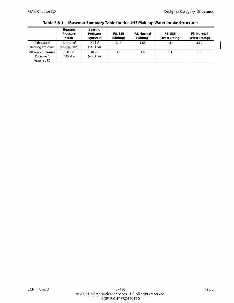
FSAR: Chapter 3.0 Design of Category I Structures
Table 3.8-1—{Basemat Summary Table for the UHS Makeup Water Intake Structure} Bearing Pressure (Static)
Bearing Pressure
(Dynamic)FS, SSE
(Sliding)FS, Normal
(Sliding)FS, SSE
(Overturning)FS, Normal
(Overturning)Calculated
Bearing Pressure5.15.5 ksf
(245263 kPa)9.3 ksf
(445 kPa)1.15 1.65 1.11 8.10
Allowable Bearing Pressure /
Required FS
8.0 ksf (385 kPa)
10 ksf (480 kPa)
1.1 1.5 1.1 1.5
CCNPP Unit 3 3–126 Rev. 5© 2007 UniStar Nuclear Services, LLC. All rights reserved.
COPYRIGHT PROTECTED

FSAR: Chapter 3.0
Design of Category I Structures
CCNPP U
nit 33–127
Rev.5©
2007 UniStar N
uclear Services, LLC. All rights reserved.
COPYRIG
HT PRO
TECTED
Duct Banks)}
Figure 3.8-1—{Schematic Site Plan of Seismic Category I Buried Utilities (Electrical
FSAR: Chapter 3.0 Design of Category I StructuresSecurity-Sensitive Information withhold from public disclosure under 10 CFR 2.390
]
Figure 3.8-2—{Schematic Site Plan of Seismic Category I Buried Utilities at the NI (Electrical Duct Banks)}
[
Security-Sensitive Information
CCNPP Unit 3 3–128 Rev. 5© 2007 UniStar Nuclear Services, LLC. All rights reserved.
COPYRIGHT PROTECTED

FSAR: Chapter 3.0
Design of Category I Structures
CCNPP U
nit 33–129
Rev.5©
2007 UniStar N
uclear Services, LLC. All rights reserved.
COPYRIG
HT PRO
TECTED
und Piping)}
Figure 3.8-3—{Schematic Site Plan of Seismic Category I Buried Utilities (Undergro
FSAR: Chapter 3.0 Design of Category I StructuresSecurity-Sensitive Information withhold from public disclosure under 10 CFR 2.390
]
Figure 3.8-4—{Schematic Site Plan of Seismic Category I Buried Utilities (Underground Piping)}
[
Security-Sensitive Information
CCNPP Unit 3 3–130 Rev. 5© 2007 UniStar Nuclear Services, LLC. All rights reserved.
COPYRIGHT PROTECTED

FSAR: Chapter 3.0
Design of Category I Structures
CCNPP U
nit 33–131
Rev.5©
2007 UniStar N
uclear Services, LLC. All rights reserved.
COPYRIG
HT PRO
TECTED
take Structure (Partial View of
Figure 3.8-5—{Isometric View of the GT STRUDL Finite Element Model for the UHS Makeup Water InBasemat, Exterior Walls and Interior Divider Walls)}
FSAR: Chapter 3.0 Mechanical Systems and Components
3.9 MECHANICAL SYSTEMS AND COMPONENTS
This section of the U.S. EPR FSAR is incorporated by reference with the supplements as described in the following sections.
3.9.1 SPECIAL TOPICS FOR MECHANICAL COMPONENTS
No departures or supplements.
3.9.1.1 Design Transients
No departures or supplements.
3.9.1.2 Computer Programs Used in Analyses
The U.S. EPR FSAR includes the following COL Holder Items in Section 3.9.1.2:
Pipe stress and support analysis will be performed by a COL applicant that references the U.S. EPR design certification.
A COL applicant that references the U.S. EPR design certification will either use a piping analysis program based on the computer codes described in Section 3.9.1 and Appendix 3C or will implement an NRC-approved benchmark program using models specifically selected for the U.S. EPR.
These COL Holder Items are addressed as follows:
{Constellation Generation Group Calvert Cliffs 3 Nuclear Project, LLC and UniStar Nuclear Operating Services, LLC} shall perform the required pipe stress and support analysis and shall utilize a piping analysis program based on the computer codes described in U.S. EPR FSAR Section 3.9.1 and U.S. EPR FSAR Appendix 3C.
3.9.1.3 Experimental Stress Analysis
No departures or supplements.
3.9.1.4 Considerations for the Evaluation of the Faulted Condition
No departures or supplements.
3.9.1.5 References
No departures or supplements.
3.9.2 DYNAMIC TESTING AND ANALYSIS OF SYSTEMS, COMPONENTS, AND EQUIPMENT
No departures or supplements.
3.9.2.1 Piping Vibration, Thermal Expansion, and Dynamic Effects
No departures or supplements.
3.9.2.2 Seismic Analysis and Qualification of Seismic Category I Mechanical Equipment
No departures or supplements.
CCNPP Unit 3 3–132 Rev. 5© 2007 UniStar Nuclear Services, LLC. All rights reserved.
COPYRIGHT PROTECTED

FSAR: Chapter 3.0 Mechanical Systems and Components
3.9.2.3 Dynamic Response Analysis of Reactor Internals Under Operational Flow Transients and Steady-State Conditions
No departures or supplements.
3.9.2.4 Preoperational Flow-Induced Vibration Testing of Reactor Internals
The U.S. EPR FSAR includes the following COL Holder Item in Section 3.9.2.4:
A COL applicant that references the U.S. EPR design certification will submit the results from the vibration assessment program for the U.S. EPR RPV internals, in accordance with Regulatory Guide 1.20.
In addition, Section 3.9.2.4 of Regulatory Guide 1.206 (NRC, 2007b) requests the following information for COL applicants with a prototype reactor:
For a prototype reactor, if the FIV testing of reactor internals is incomplete at the time the COL application is filed, the applicant should provide documentation describing the implementation program, including milestones, completion dates and expected conclusions.
The COL Holder Item and Regulatory Guide 1.206 request are addressed as follows:
{The U. S. EPR FSAR designates the Reactor Pressure Vessel (RPV) internals as a prototype design in accordance with the guidance of Regulatory Guide 1.20 (NRC, 2007a). The CCNPP Unit 3 RPV internals are currently classified as the U.S. EPR prototype for RPV internals testing. However, should a comprehensive vibration assessment program for an EPR unit other than CCNPP Unit 3 be completed and approved by the U.S Nuclear Regulatory Commission prior to initiation of start-up testing at CCNPP Unit 3, CCNPP Unit 3 will be reclassified as a non-prototype Category I RPV internals design and the associated experimental and/or analytical justification, including any required changes to the comprehensive vibration assessment program, will be provided to the U.S Nuclear Regulatory Commission for review and approval.
A methodology for the comprehensive vibration assessment program that the U.S. Nuclear Regulatory Commission considers acceptable for use is provided in Regulatory Guide 1.20 and shall be utilized at CCNPP Unit 3. For CCNPP Unit 3, performance of vibration testing during Hot Functional Testing, and associated field testing, shall be as described in U.S. EPR FSAR Section 3.9.2.4 and in accordance with the Hot Functional Testing milestone identified in U.S. EPR FSAR Figure 14.2-1.
The visual inspection plan of the comprehensive vibration assessment program to be used for the prototype RPV internals at CCNPP Unit 3 involves performance of visual inspections before and after the preoperational tests of the RPV internals. These visual examinations are concerned with the accessible areas of the RPV internals, and in particular the fastening devices, the bearings surfaces, the interfaces between the RPV internals parts that are likely to experience relative motions, and the inside of the RPV. The visual inspections of the lower and upper RPV internals shall be performed at CCNPP Unit 3 as described in U.S. EPR FSAR Tables 3.9.2-1 through 3.9.2-5.
The activities and milestones for implementation of the comprehensive vibration assessment program at CCNPP Unit 3 are as follows.
CCNPP Unit 3 3–133 Rev. 5© 2007 UniStar Nuclear Services, LLC. All rights reserved.
COPYRIGHT PROTECTED

FSAR: Chapter 3.0 Mechanical Systems and Components
A summary of the vibration analysis program, including a description of the vibration measurement and inspection phases, shall be provided to the U.S. Nuclear Regulatory Commission at least 120 days prior to initiation of Hot Functional Testing (i.e., 15 months prior to commercial operation).
Visual inspections of the RPV internals shall be performed prior to initiation of Hot Functional Testing.
Vibration testing shall be performed during Hot Functional Testing (i.e., 11 months prior to commercial operation).
Visual inspections of the RPV internals shall be performed after completion of Hot Functional Testing.
The preliminary and final comprehensive vibration assessment reports, which together summarize the results of the vibration analysis, measurement, and inspection programs (including correlation of analysis and test results), shall be submitted to the U.S. Nuclear Regulatory Commission at least 30 days prior to initial fuel loading (i.e., 9 months prior to commercial operation) and at least 30 days prior to initial criticality (i.e., 7 months prior to commercial operation), respectively. This schedule is within the Regulatory Guide 1.20 request to submit these reports within 60 and 180 days, respectively, following the completion of vibration testing.
These milestones are aligned with the milestones set forth in U. S. EPR FSAR Section 14.2 for the initial plant test program. The expected date for the start of commercial operation at CCNPP Unit 3 is December 31, 2015.}
3.9.2.5 Dynamic System Analysis of the Reactor Internals Under Faulted Conditions
No departures or supplements.
3.9.2.6 Correlations of Reactor Internals Vibration Tests with the Analytical Results
No departures or supplements.
3.9.2.7 References
{NRC, 2007a. Comprehensive Vibration Assessment Program for Reactor Internals during Preoperational And Initial Startup Testing, Regulatory Guide 1.20, Revision 3, U.S. Nuclear Regulatory Commission, March 2007.
NRC, 2007b. Combined License Applications for Nuclear Power Plants (LWR Edition), Regulatory Guide 1.206, Revision 0, U. S. Nuclear Regulatory Commission, June 2007.}
3.9.3 ASME CODE CLASS 1, 2, AND 3 COMPONENTS, COMPONENT SUPPORTS, AND CORE SUPPORT STRUCTURES
The U.S. EPR FSAR includes the following COL Holder Item in Section 3.9.3:
A COL applicant that references the U.S. EPR design certification will prepare the design specifications and design reports for ASME Class 1, 2, and 3 components, piping, supports, and core support structures that comply with and are certified to the requirements of Section III of the ASME Code.
CCNPP Unit 3 3–134 Rev. 5© 2007 UniStar Nuclear Services, LLC. All rights reserved.
COPYRIGHT PROTECTED

FSAR: Chapter 3.0 Mechanical Systems and Components
This COL Holder Item is addressed as follows:
{Constellation Generation Group Calvert Cliffs 3 Nuclear Project, LLC and UniStar Nuclear Operating Services, LLC} shall prepare the design specifications and design reports for ASME Class 1, 2, and 3 components that comply with and are certified to the requirements of Section III of the ASME Code (ASME, 2004). The design specifications shall be prepared prior to procurement of the components while the ASME code reports shall be prepared during as-built reconciliation of the systems and components conducted prior to fuel load.
3.9.3.1 Loading Combinations, System Operating Transients, and Stress Limits
The U.S. EPR FSAR includes the following COL Holder Item in Section 3.9.3.1:
A COL applicant that references the U.S. EPR design certification will provide a summary of the maximum total stress, deformation (where applicable), and cumulative usage factor values for each of the component operating conditions for ASME Code Class 1 components. For those values that differ from the allowable limits by less than 10 percent, the COL applicant will provide the contribution of each of the loading categories (e.g., seismic, pipe rupture, dead weight, pressure, and thermal) to the total stress for each maximum stress value identified in this range.
This COL Holder Item is addressed as follows:
{Constellation Generation Group Calvert Cliffs 3 Nuclear Project, LLC and UniStar Nuclear Operating Services, LLC shall provide a summary of the maximum total stress, deformation (where applicable), and cumulative usage factor values for each of the component operating conditions for ASME Code Class 1 components. For those values that differ from the allowable limits by less than 10 percent, Constellation Generation Group Calvert Cliffs 3 Nuclear Project, LLC and UniStar Nuclear Operating Services, LLC shall provide the contribution of each of the loading categories (e.g., seismic, pipe rupture, dead weight, pressure, and thermal) to the total stress for each maximum stress value identified in this range. This information shall be supplied prior to procurement of the ASME Code Class 1 components.}
3.9.3.1.1 Loads for Components, Component Supports, and Core Support Structures
The U.S. EPR FSAR includes the following COL Item in Section 3.9.3.1.1:
As noted in ANP-10264(NP), should a COL applicant that references the U.S. EPR design certification find it necessary to route Class 1, 2, and 3 piping not included in the U.S. EPR design certification so that it is exposed to wind and tornadoes, the design must withstand the plant design-bases loads for this event.
This COL Item is addressed as follows:
{Constellation Generation Group Calvert Cliffs 3 Nuclear Project, LLC and UniStar Nuclear Operating Services, LLC} shall route Class 1, 2, or 3 piping not included in the U.S. EPR design certification in a manner so that it is not exposed to wind or tornadoes.
The U.S. EPR FSAR includes the following COL Holder Items in Section 3.9.3.1.1:
As noted in ANP-10264(NP), a COL applicant that references the U.S. EPR design certification will confirm that thermal deflections do not create adverse conditions during hot functional testing.
CCNPP Unit 3 3–135 Rev. 5© 2007 UniStar Nuclear Services, LLC. All rights reserved.
COPYRIGHT PROTECTED

FSAR: Chapter 3.0 Mechanical Systems and Components
A COL applicant that references the U.S. EPR design certification will examine the feedwater line welds after hot functional testing prior to fuel loading and at the first refueling outage, in accordance with NRC Bulletin 79-13. A COL applicant that references the U.S. EPR design certification will report the results of inspections to the NRC, in accordance with NRC Bulletin 79-13.
These COL Holder Items are addressed as follows:
{Constellation Generation Group Calvert Cliffs 3 Nuclear Project, LLC and UniStar Nuclear Operating Services, LLC} shall:
Confirm that thermal deflections do not create adverse conditions during hot functional testing.
Examine the feedwater line welds after hot functional testing prior to fuel loading and at the first refueling outage, and will report the results of the inspections to the U.S. Nuclear Regulatory Commission, in accordance with NRC Bulletin 79-13 (NRC, 1979).
3.9.3.1.2 Load Combinations and Stress Limits for Class 1 Components
No departures or supplements.
3.9.3.1.3 Load Combinations and Stress Limits for Class 2 and 3 Components
No departures or supplements.
3.9.3.1.4 Load Combinations and Stress Limits for Class 1 Piping
No departures or supplements.
3.9.3.1.5 Load Combinations and Stress Limits for Class 2 and 3 Piping
No departures or supplements.
3.9.3.1.6 Load Combinations and Stress Limits for Core Support Structures
No departures or supplements.
3.9.3.1.7 Load Combinations and Stress Limits for Class 1, 2 and 3 Component Supports
No departures or supplements.
3.9.3.1.8 Load Combinations and Stress Limits for Class 1, 2 and 3 Pipe Supports
No departures or supplements.
3.9.3.1.9 Piping Functionality
No departures or supplements.
3.9.3.2 Design and Installation of Pressure-Relief Devices
No departures or supplements.
CCNPP Unit 3 3–136 Rev. 5© 2007 UniStar Nuclear Services, LLC. All rights reserved.
COPYRIGHT PROTECTED

FSAR: Chapter 3.0 Mechanical Systems and Components
3.9.3.3 Pump and Valve Operability Assurance
No departures or supplements.
3.9.3.4 Component Supports
No departures or supplements.
3.9.3.5 References
{ASME, 2004. Rules for Construction of Nuclear Facility Components, ASME Boiler and Pressure Vessel Code, Section III, The American Society of Mechanical Engineers, 2004 edition.
NRC, 1979. Cracking in Feedwater System Piping, NRC Bulletin 79-13, Revision 2, U.S. Nuclear Regulatory Commission, October 16, 1979.}
3.9.4 CONTROL ROD DRIVE SYSTEM
No departures or supplements.
3.9.5 REACTOR PRESSURE VESSEL INTERNALS
No departures or supplements.
3.9.6 FUNCTIONAL DESIGN, QUALIFICATION, AND INSERVICE TESTING PROGRAMS FOR PUMPS, VALVES, AND DYNAMIC RESTRAINTS
The U.S. EPR FSAR includes the following COL Holder and Applicant Items, respectively, in Section 3.9.6:
A COL applicant that references the U.S. EPR design certification will submit the PST program and IST program for pumps, valves, and snubbers as required by 10 CFR 50.55a.
A COL applicant that references the U.S. EPR design certification will identify the implementation milestones and applicable ASME OM Code for the preservice and inservice examination and testing programs. These programs will be consistent with the requirements in the latest edition and addenda of the OM Code incorporated by reference in 10 CFR 50.55a on the date 12 months before the date for initial fuel load.
These COL Holder and Applicant Items are addressed as follows:
{Calvert Cliffs 3 Nuclear Project, LLC and UniStar Nuclear Operating Services, LLC} will implement the preservice testing (PST) and inservice testing (IST) programs for pumps, valves, and dynamic restraints described in Section 3.9.6 of the U.S. EPR FSAR. Because of site specific needs, the following supplements will be included in the programs.
{The UHS Makeup Water System is a site-specific safety-related system that is subject to preservice testing (PST) and inservice testing (IST) program requirements identified in 10 CFR 50.55a. This system’s pumps, valves and piping components included in these testing programs are provided in Table 3.9-1 and Table 3.9-2. There are no snubbers in the UHS Makeup Water System.}
{Constellation Generation Group Calvert Cliffs 3 Nuclear Project, LLC and UniStar Nuclear Operating Services, LLC} shall submit the PST and IST programs prior to performing the tests and following the start of construction and prior to the anticipated date of commercial
CCNPP Unit 3 3–137 Rev. 5© 2007 UniStar Nuclear Services, LLC. All rights reserved.
COPYRIGHT PROTECTED

FSAR: Chapter 3.0 Mechanical Systems and Components
operation, respectively. The implementation milestones for these programs are provided in Table 13.4-1. These programs shall include the implementation milestones and applicable ASME OM Code (ASME, 2004b) and shall be consistent with the requirements in the latest edition and addenda of the OM Code incorporated by reference in 10 CFR 50.55a (CFR, 2008) on the date 12 months before the date for initial fuel load.
3.9.6.1 Functional Design and Qualification of Pumps, Valves, and Dynamic Restraints
{The UHS Makeup Water System, including the individual components and the UHS Makeup Water Intake Structure, are designed, manufactured, tested, and installed in such fashion as to ensure and facilitate actual demonstration of design basis performance.
Component design considerations include function and performance requirements that support the overall system performance, as well as materials of construction, wear tolerances, and configuration that are selected to assure accommodation of service limits and the required component longevity. In addition, provisions are designed in as necessary for measuring or examining component characteristics such as vibration, bearing temperatures, or pressure boundary thickness, using either permanent or temporary equipment, to demonstrate during actual operating conditions that they are within the design tolerances.
Component manufacturing is accomplished in accordance with quality program requirements that verify component physical and material requirements. Pre-approved performance test procedures are used by the manufacturer to demonstrate/verify that actual component capabilities meet design requirements.
The UHS Makeup Water System layout is completed with consideration of maintenance and repair efforts, parameters to be monitored during operation, and periodic inspection and testing. Accordingly, sufficient space is allocated around components, system test connections are accessible, and the test bypass line is designed specifically for demonstration of the system’s maximum flow rate at design conditions as specified in the plant accident analyses. There are no snubbers incorporated into this system.
The UHS Makeup Water System pumps, valves and piping components will incorporate the necessary test and monitoring connections to demonstrate the capacity of the pumps and valves to perform their intended function through the full range of system differential pressures and flows at ambient temperatures and available voltages.
Particular attention will be given to flow-induced loading in functional design and qualification to degraded flow conditions to account for the presence of debris, impurities, and contaminants in the fluid system.}
3.9.6.2 Inservice Testing Program for Pumps
The U.S. EPR FSAR includes the following COL Items in Section 3.9.6.2:
A COL applicant that references the U.S. EPR design certification will identify any additional site-specific pumps in Table 3.9.6-1 to be included within the scope of the IST program.
This COL Item is addressed as follows:
Table 3.9-1 identifies the additional site-specific pumps that are included within the scope of the IST program.
CCNPP Unit 3 3–138 Rev. 5© 2007 UniStar Nuclear Services, LLC. All rights reserved.
COPYRIGHT PROTECTED

FSAR: Chapter 3.0 Mechanical Systems and Components
3.9.6.3 Inservice Testing Program for Valves
The U.S. EPR FSAR includes the following COL Items in Section 3.9.6.3:
A COL applicant that references the U.S. EPR design certification will identify any additional site-specific valves in Table 3.9.6-2 to be included within the scope of the IST program.
This COL Item is addressed as follows:
Table 3.9-2 identifies the additional site-specific valves that are included within the scope of the IST program.
In addition, the following supplement to U.S. EPR FSAR Section 3.9.6.3 is provided:
{The UHS Makeup Water System Class 3 site-specific valves (motor-operated, manually-operated, check, safety, and relief valves) will be tested in accordance with ASME OM 2004 code, section ISTC (ASME, 2004b).}
3.9.6.3.1 Inservice Testing Program for Motor-Operated Valves
No departures or supplements.
3.9.6.3.2 Inservice Testing Program for Power-Operated Valves Other Than MOVs
{There are no power-operated valves in the UHS Makeup Water System, other than the MOVs.}
3.9.6.3.3 Inservice Testing Program for Check Valves
No departures or supplements.
3.9.6.3.4 Pressure Isolation Valve Leak Testing
No departures or supplements.
3.9.6.3.5 Containment Isolation Valve Leak Testing
{There are no Class 3 site-specific containment isolation valves in the UHS Makeup Water System.}
3.9.6.3.6 Inservice Testing Program for Safety and Relief Valves
No departures or supplements.
3.9.6.3.7 Inservice Testing Program for Manually Operated Valves
No departures or supplements.
3.9.6.3.8 Inservice Testing Program for Explosively Actuated Valves
{There are no Class 3 site-specific explosively actuated valves in the UHS Makeup Water System.}
3.9.6.4 Inservice Testing Program for Dynamic Restraints
The U.S. EPR FSAR includes the following COL Holder Item in Section 3.9.6.4:
CCNPP Unit 3 3–139 Rev. 5© 2007 UniStar Nuclear Services, LLC. All rights reserved.
COPYRIGHT PROTECTED

FSAR: Chapter 3.0 Mechanical Systems and Components
A COL applicant that references the U.S. EPR design certification will provide a table identifying the safety-related systems and components that use snubbers in their support systems, including the number of snubbers, type (hydraulic or mechanical), applicable standard, and function (shock, vibration, or dual-purpose snubber). For snubbers identified as either a dual-purpose or vibration arrester type, the COL applicant shall indicate whether the snubber or component was evaluated for fatigue strength. Per ASME Code Section III, Subsection NF, the fatigue evaluation is not required for shock snubbers.
This COL Holder Item is addressed as follows:
{Constellation Generation Group Calvert Cliffs 3 Nuclear Project, LLC and UniStar Nuclear Operating Services, LLC} shall provide a table identifying the safety-related systems and components that use snubbers in their support systems, including the number of snubbers, type (hydraulic or mechanical), applicable standard, and function (shock, vibration, or dual-purpose snubber). For snubbers identified as either a dual-purpose or vibration arrester type, {Constellation Generation Group Calvert Cliffs 3 Nuclear Project, LLC and UniStar Nuclear Operating Services, LLC} shall denote whether the snubber or component was evaluated for fatigue strength. Per ASME Section III, Subsection NF (ASME, 2004a), the fatigue evaluation shall not be required for shock snubbers. This information shall be provided prior to installation of any of the snubbers.
{The UHS Makeup Water System does not incorporate snubbers in the system design.}
3.9.6.5 Relief Requests and Alternative Authorizations to the OM Code
No departures or supplements.
3.9.6.6 References
{ASME, 2004a. Rules for Construction of Nuclear Facility Components, ASME Boiler and Pressure Vessel Code, Section III, The American Society of Mechanical Engineers, 2004 edition.
ASME, 2004b. Code for Operation and Maintenance of Nuclear Power Plants, ASME OM Code, The American Society of Mechanical Engineers, 2004 edition.
CFR, 2008. Codes and Standards, Title 10, Code of Federal Regulations, Part 50.55a, U. S. Nuclear Regulatory Commission, 2008.}
CCNPP Unit 3 3–140 Rev. 5© 2007 UniStar Nuclear Services, LLC. All rights reserved.
COPYRIGHT PROTECTED

FSAR: Chapter 3.0
Mechanical System
s and Components
CCNPP U
nit 33–141
Rev.5©
2007 UniStar N
uclear Services, LLC. All rights reserved.
COPYRIG
HT PRO
TECTED
System).
).
ts}
P
sting and Frequency 6, 9
2
Differential Pressure Flow Rate Vibration5
3 Q/2Y Q/2Y Q/2Y
3 Q/2Y Q/2Y Q/2Y
3 Q/2Y Q/2Y Q/2Y
3 Q/2Y Q/2Y Q/2Y
Notes:
1. Pump is directly coupled to a constant speed synchronous or induction type driver.
2. Discharge pressure is a required parameter for positive displacement pumps only.
3. dP is not a required parameter for positive displacement pumps (not applicable to site-specific UHS Makeup Water Intake
4. Variable speed pumps only.
5. Displacement or velocity.
6. Test and their frequency are in accordance with subsection ISTB of ASME OM code.
7. This test does not apply to positive displacement pumps (not applicable to site-specific UHS Makeup Water System).
8. The U. S. EPR subscribes to the Kraftworks Kennzeichen System (KKS) for coding and nomenclature of SSCs.
9. Group B pumps go through a Quarterly Group B Test Procedure (ISTB-5122) and biennially Comprehensive test (ISTB-5123
Table 3.9-1—{Site -Specific Inservice Pump Testing Program Requiremen
ump ID 8 DescriptionPump Type
ASME Code Class
ASME Code
Group
Te
Rotational Speed 4
Pump DischargePressure
0PED 10 AP001 A
Ultimate Heat Sink (UHS) Makeup Water Pump Vertical Solid Shaft
3 B N/A1 N/A
0PED 20 AP001 A
Ultimate Heat Sink (UHS) Makeup Water Pump Vertical Solid Shaft
3 B N/A1 N/A
0PED 30 AP001 A
Ultimate Heat Sink (UHS) Makeup Water Pump Vertical Solid Shaft
3 B N/A1 N/A
0PED 40 AP001 A
Ultimate Heat Sink (UHS) Makeup Water Pump Vertical Solid Shaft
3 B N/A1 N/A
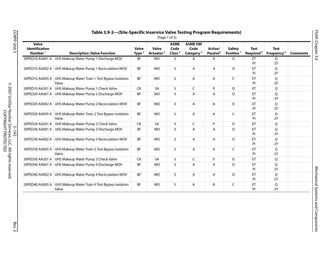
FSAR: Chapter 3.0
Mechanical System
s and Components
CCNPP U
nit 33–142
Rev.5©
2007 UniStar N
uclear Services, LLC. All rights reserved.
COPYRIG
HT PRO
TECTED
ts}
y n 7
Test Required 8
Test Frequency 9 Comments
30 ETPI
Q2Y
30 ETPI
Q2Y
30 ETPI
Q2Y
30 ET Q30 ET
PIQ2Y
30 ETPI
Q2Y
30 ETPI
Q2Y
30 ET Q30 ET
PIQ2Y
30 ETPI
Q2Y
30 ETPI
Q2Y
30 ET Q30 ET
PIQ2Y
30 ETPI
Q2Y
30 ETPI
Q2Y
Table 3.9-2—{Site-Specific Inservice Valve Testing Program Requiremen (Page 1 of 3)
Valve Identification
Number 1 Description /Valve FunctionValve Type 2
Valve Actuator 3
ASME Code
Class 4
ASME OM Code
Category 5Active/
Passive6Safet
PositioPED10 AA001 A UHS Makeup Water Pump 1 Discharge MOV BF MO 3 A A O
PED10 AA002 A UHS Makeup Water Pump 1 Recirculation MOV BF MO 3 A A O
PED10 AA005 A UHS Makeup Water Train 1 Test Bypass Isolation Valve
BF MO 3 A A C
PED10 AA201 A UHS Makeup Water Pump 1 Check Valve CK SA 3 C P OPED20 AA001 A UHS Makeup Water Pump 2 Discharge MOV BF MO 3 A A O
PED20 AA002 A UHS Makeup Water Pump 2 Recirculation MOV BF MO 3 A A O
PED20 AA005 A UHS Makeup Water Train 2 Test Bypass Isolation Valve
BF MO 3 A A C
PED20 AA201 A UHS Makeup Water Pump 2 Check Valve CK SA 3 C P OPED30 AA001 A UHS Makeup Water Pump 3 Discharge MOV BF MO 3 A A O
PED30 AA002 A UHS Makeup Water Pump 3 Recirculation MOV BF MO 3 A A O
PED30 AA005 A UHS Makeup Water Train 3 Test Bypass Isolation Valve
BF MO 3 A A C
PED30 AA201 A UHS Makeup Water Pump 3 Check Valve CK SA 3 C P OPED40 AA001 A UHS Makeup Water Pump 4 Discharge MOV BF MO 3 A A O
PED40 AA002 A UHS Makeup Water Pump 4 Recirculation MOV BF MO 3 A A O
PED40 AA005 A UHS Makeup Water Train 4 Test Bypass Isolation Valve
BF MO 3 A A C

FSAR: Chapter 3.0
Mechanical System
s and Components
CCNPP U
nit 33–143
Rev.5©
2007 UniStar N
uclear Services, LLC. All rights reserved.
COPYRIG
HT PRO
TECTED
30 ET QLA ET
PI5Y2Y
See Note 10
ts}
y n 7
Test Required 8
Test Frequency 9 Comments
PED40 AA201 A UHS Makeup Water Pump 4 Check Valve CK SA 3 C P OTER UHS Makeup Water System Manual Valves Various MA 3 B P O/C
Table 3.9-2—{Site-Specific Inservice Valve Testing Program Requiremen (Page 2 of 3)
Valve Identification
Number 1 Description /Valve FunctionValve Type 2
Valve Actuator 3
ASME Code
Class 4
ASME OM Code
Category 5Active/
Passive6Safet
Positio

FSAR: Chapter 3.0
Mechanical System
s and Components
CCNPP U
nit 33–144
Rev.5©
2007 UniStar N
uclear Services, LLC. All rights reserved.
COPYRIG
HT PRO
TECTED
itions. Valves are exercised to the position
ts}
y n 7
Test Required 8
Test Frequency 9 Comments
Notes:1. The U. S. EPR subscribes to the Kraftworks Kennzeichen System (KKS) for coding and nomenclature of SSCs.2. Valve Type
GB – GlobeGT – GateCK – CheckRV – ReliefRD – Rupture DiskDI – DiaphragmBF – ButterflyPL – Plug
3. Valve ActuatorMO – Motor-operatedSO – Solenoid-operatedAO – Air-operatedHO – Hydraulic-operatedSA – Self-actuatedMA – ManualPA – Pilot-actuated
4. ASME Code Class as determined by quality groups from Regulatory 1.26.5. ASME Code Category A, B, C, D as defined in ASME OM Code 2004, Subsection ISTC-13006. ASME functional category as defined in ASME OM Code 2004, Subsection ISTC-13007. Valve safety function positions(s), specify both positions for valves that perform a safety function in both the open and closed pos
(s) required to fulfill their safety function(s). Check valve tests include both open and closed tests.8. Required tests per ASME OM Code 2004, Subsection ISTC-3000
LT – Leakage test per Table ISTC-3500-1 and ISTC-3000ET – Exercise test per Table ISTC-3500-1 and ISTC-3510-1, nominally every 3 monthsPI – Position indication verification per Table ISTC-3500-1 and ISTC-3700ST – Stroke time per test per ISTC-5000 (in conjunction with exercise test).
9. Test frequencies abbreviations per NUREG-1482, Revision 1:Q test performed once every 92 daysCS – test performed during cold shutdown, but no more frequently than once every 92 daysRF – test performed each refueling outage2Y – test performed every 2 years5Y – test performed once every 5 years (per ASME OM, ISTC-3540)RV – test relief valve at OM schedule.
10. Table entries for manual valves will be developed during detailed design engineering.
Table 3.9-2—{Site-Specific Inservice Valve Testing Program Requiremen (Page 3 of 3)
Valve Identification
Number 1 Description /Valve FunctionValve Type 2
Valve Actuator 3
ASME Code
Class 4
ASME OM Code
Category 5Active/
Passive6Safet
Positio

FSAR: Chapter 3.0 Seismic and Dynamic Qualification of Mechanical And Electrical Equipment
3.10 SEISMIC AND DYNAMIC QUALIFICATION OF MECHANICAL AND ELECTRICAL EQUIPMENT
{This section of the U.S. EPR FSAR is incorporated by reference with the supplements as described in the following sections.
For CCNPP Unit 3, seismic and dynamic qualification of site-specific mechanical and electrical equipment (identified in Table 3.10-1) includes equipment associated with the:
UHS Makeup Water System, including the UHS Makeup Water Intake Structure and the UHS Electrical Building; and
Fire Protection System components that are required to protect equipment required to achieve safe shutdown following an earthquake, including the Fire Protection Building and Fire Water Storage Tanks.
Results of seismic and dynamic qualification of site-specific equipment by testing and/or analysis were not available at the time of submittal of the original COL application. Thus, in conformance with NRC Regulatory Guide 1.206 (NRC, 2007), a seismic qualification implementation program is provided. As depicted in Table 3.10-2, the qualification program will be implemented in five major phases.
Phase I (Seismic Qualification Methodology) involves the development of a summary table for site-specific equipment. This summary table shall:
List site-specific equipment, along with the associated equipment identification number.
Define the building in which each equipment is located, along with the equipment mounting elevation.
Clarify whether the equipment is wall mounted, floor mounted, or line mounted.
For mechanical equipment, identify if the equipment is active or passive.
Provide a description of the intended mounting (e.g., skid mounted versus mounted directly on the floor, welded versus bolted, etc.).
List the applicable In-Structure Response Spectra or, for line mounted equipment, the required input motion.
Define operability and functionality requirements.
Identify the acceptable qualification methods (i.e., analysis, testing, and/or a combination of both).
Provide a requirement for environmental testing prior to seismic testing, when applicable.
The basis and criteria established in Phase I shall be used as technical input to the Phase II (Specification Development) technical requirements that will be provided to bidders. In addition, the specification will include the applicable seismic qualification requirements of the U.S. EPR FSAR which are incorporated by reference in this section (e.g., invoking industry standard IEEE 344).
CCNPP Unit 3 3–145 Rev. 5© 2007 UniStar Nuclear Services, LLC. All rights reserved.
COPYRIGHT PROTECTED

FSAR: Chapter 3.0 Seismic and Dynamic Qualification of Mechanical And Electrical Equipment
The technical specification developed in Phase II shall also outline the requirements for the submittal (with each bidder’s proposal) of either a detailed seismic qualification methodology or, for cases where seismic analysis and/or testing has previously been performed, the seismic qualification report. The seismic qualification methodology for each bidder shall be required to carry the overall methodology of Phase I to a much more detailed level. As examples, the detailed methodology shall be required to address:
Which portions of the equipment will be qualified by analysis, testing and/or a combination of both, with technical justification.
The technical justification when other than bi-axial, phase incoherent test input motions (or multiple input-motions in-phase and 180 degrees out-of-phase) are used for floor mounted equipment.
Early in the Procurement Phase, Phase III (Technical Bid Evaluations) shall be performed. The scope of Phase III will vary depending on whether the proposed seismic qualification for the specific piece of equipment will utilize analysis and/or testing performed previously. For each case where seismic qualification (by either analysis and/or testing) has not been performed, the detailed methodology shall be compared with the technical specification requirements. For each case where seismic qualification has been performed previously and the reports are submitted with the proposal, the Technical Bid Evaluation shall consist of a detailed review of the seismic qualification report, including a comparison of the detailed methodology employed versus the technical specification requirements. The technical review shall be performed expeditiously to mitigate the potential for anomalies (e.g., those pertaining to test equipment calibration) to be identified late in the Procurement cycle. When applicable, Requests for Clarification (RFC) shall be provided to the bidder for resolution of anomalies. If, after vendor clarification, the existing qualification report is determined to be insufficient technically, additional analysis and/or testing may be required.
During Phase IV (New Seismic Analysis and/or Testing), the supplier shall perform new analysis and/or testing, to either seismically qualify the equipment or, if a previously submitted qualification report is determined to be insufficient, to supplement the previously submitted seismic qualification. The analysis (or analysis portion of combined analysis and test seismic qualification) shall be reviewed in detail, to assure compliance with the technical specification requirements. Where testing is to be employed, a detailed review of the test procedure shall be performed at least one month prior to the test. New testing will be independently observed to assure conformance with the reviewed test procedure.
Phase V (Documentation of Results) shall consist of the preparation of a Seismic Qualification Data Package (SQDP) for each piece of equipment seismically qualified. As a minimum, the SQDP will include information required in the U.S. EPR FSAR, Appendix D, Attachment F.}
3.10.1 SEISMIC QUALIFICATION CRITERIA
3.10.1.1 Qualification Standards
The U.S. EPR FSAR includes the following COL Item in Section 3.10.1.1:
A COL applicant that references the U. S. EPR design certification will identify any additional site-specific components that need to be added to the equipment list in Table 3.10-1.
This COL Item is addressed as follows:
CCNPP Unit 3 3–146 Rev. 5© 2007 UniStar Nuclear Services, LLC. All rights reserved.
COPYRIGHT PROTECTED

FSAR: Chapter 3.0 Seismic and Dynamic Qualification of Mechanical And Electrical Equipment
A list of site-specific seismically and dynamically qualified mechanical, electrical, and instrumentation and control equipment is provided in Table 3.10-1. Table 3.10-1 also identifies the type of environment to which the equipment is subjected.
3.10.1.2 Performance Requirements for Seismic Qualification
No departures or supplements.
3.10.1.3 Acceptance Criteria
No departures or supplements.
3.10.1.4 Input Motion
{No departures or supplements.}
3.10.2 METHODS AND PROCEDURES FOR QUALIFYING MECHANICAL, ELECTRICAL AND I&C EQUIPMENT
The U.S. EPR FSAR includes the following COL Holder Item in Section 3.10.2:
If experience data are used to establish equipment qualification, a COL applicant that references the U. S. EPR design certification will document the qualification methodology and supporting data.
This COL Holder Item is addressed as follows:
{Constellation Generation Group Calvert Cliffs 3 Nuclear Project, LLC and UniStar Nuclear Operating Services, LLC} shall not use experience data to establish equipment qualification.
3.10.2.1 Seismic Qualification of Electrical Equipment and Instrumentation
No departures or supplements.
3.10.2.2 Seismic Qualification of Active Mechanical Equipment
No departures or supplements.
3.10.2.3 Seismic Qualification of Non-Active Mechanical Equipment
No departures or supplements.
3.10.3 METHODS AND PROCEDURES FOR QUALIFYING SUPPORTS OF MECHANICAL AND ELECTRICAL EQUIPMENT AND INSTRUMENTATION
No departures or supplements.
3.10.4 TEST AND ANALYSIS RESULTS AND EXPERIENCE DATABASE
The U.S. EPR FSAR includes the following COL Holder Item in Section 3.10.4:
A COL applicant that references the U. S. EPR design certification will create and maintain the SQDP file during the equipment selection and procurement phase.
This COL Holder Item is addressed as follows:
CCNPP Unit 3 3–147 Rev. 5© 2007 UniStar Nuclear Services, LLC. All rights reserved.
COPYRIGHT PROTECTED

FSAR: Chapter 3.0 Seismic and Dynamic Qualification of Mechanical And Electrical Equipment
{Constellation Generation Group Calvert Cliffs 3 Nuclear Project, LLC and UniStar Nuclear Operating Services, LLC} shall create and maintain the SQDP file. This activity shall be initiated during the equipment selection and procurement phase. The SQDP file shall be maintained for the life of the plant.
The U.S. EPR FSAR also includes the following COL Item in Section 3.10.4:
If the seismic and dynamic qualification testing is incomplete at the time of the COL application, a COL applicant that references the U.S. EPR design certification will submit an implementation program, including milestones and completion dates, for NRC review and approval prior to installation of the applicable equipment.
This COL Item is addressed as follows:
The seismic and dynamic qualification implementation program, including milestones and completion dates, shall be developed and submitted for U.S. Nuclear Regulatory Commission approval prior to installation of the applicable equipment.
3.10.5 REFERENCES
{NRC, 2007. Combined License Applications for Nuclear Power Plants, Regulatory Guide 1.206, Revision 0, U.S. Nuclear Regulatory Commission, June 2007.}
CCNPP Unit 3 3–148 Rev. 5© 2007 UniStar Nuclear Services, LLC. All rights reserved.
COPYRIGHT PROTECTED

FSAR: Chapter 3.0
Seismic and D
ynamic Q
ualification of Mechanical A
nd Electrical Equipment
CCNPP U
nit 33–149
Rev.5©
2007 UniStar N
uclear Services, LLC. All rights reserved.
COPYRIG
HT PRO
TECTED
quipment}
N(E
ated Function Safety Class(Note 4)
EQ Program Designation(Note 5)
UUH SI S Y (5)UH SI S Y (5)UH SI S Y (5)UH SI S Y (5)UH SI S Y (5)UH SI S Y (5)30 SI S Y (5)30 SI S Y (5)UH SI S Y (5)30 SI S Y (5)30 SI S Y (5)UH SI S Y (5)UH SI S Y (5)UH SI S Y (5)SA SI S Y (5)SA SI S Y (5)SA SI S Y (5)SA SI S Y (5)SA SI S Y (5)SA SI S Y (5)UH SI S Y (5)UH SI S Y (5)UH SI S Y (5)UH SI S Y (5)30 SI S Y (5)El SI S Y (5)El SI S Y (5)El SI S Y (5)El SI S Y (5)De SI S Y (5)
Table 3.10-1—{Seismic and Dynamic Qualifications of Mechanical and Electrical E (Page 1 of 7)
ame Tagquipment Description) Tag Number
Local AreaKKS ID(RoomLocation)
EQEnvironment(Note 1)
RadiationEnvironmentZone(Note 2)
EQ Design(Note 3)
ltimate Heat Sink (UHS) Makeup (m/u) SystemS m/u pp disch isol train 1 30PED10AA001 30UPF01001 M M ESS pp min flow vlv train 1 30PED10AA002 30UPF01001 M M ESS pp test isol train 1 30PED10AA005 30UZT M M ESS pp air rel vlv train 1 30PED10AA190 30UPF01001 M M ESS m/u pp disch chk vlv train 1 30PED10AA201 30UPF01001 M M ESS m/u pp disch press train 1 30PED10AA303 30UPF01001 M M ES
PED10CP002 low side isol 30PED10AA304 30UPF01001 M M ESPED10CP002 hi side isol 30PED10AA305 30UPF01001 M M ESS m/u low pt drain vlv train 1 30PED10AA404 30UPF01001 M M ES
PED10CP003 hi side test vlv 30PED10AA443 30UZT M M ESPED10CP003 low side test vlv 30PED10AA444 30UZT M M ESS m/u high pt vent vlv train 1 30PED10AA511 30UPF01001 M M ESS m/u pp train 1 30PED10AP001 30UPF01001 M M ESS m/u pp disch strnr train 1 30PED10AT001 30UPF01001 M M ESQ UHS m/u supp isol, train 1 30PED11AA001 30UPF01001 M M ESQ UHS m/u ret isol, train 1 30PED11AA002 30UPF01001 M M ESQ UHS m/u side vac bkr train 1 30PED11AA191 30UPF01001 M M ESQ diff press hi side isol, train 1 30PED11AA301 30UPF01001 M M ESQ diff press lo side isol train 1 30PED11AA302 30UPF01001 M M ESQ UHS m/u side lo pt drn vlv, train 1 30PED11AA400 30UPF01001 M M ESS m/u disch Flow rate Instrument 30PED10CF003 30UPF01001 M M ESS m/u Test Flow rate Instrument 30PED10CF004 30UZT M M ESS m/u Intake Structure Level Inst. 30PED10CL001 30UPF01001 M M ESS m/u strainer debris removal Valve 30PED10AA006 30UPF01001 M M ES
PED11 AC001 Fan 30PED11AN001 30UPF01001 M M ESectric Heater 30PED11AH002A 30UPF01001 M M ESectric Heater 30PED11AH002B 30UPF01001 M M ESectric Heater 30PED11AH002C 30UPF01001 M M ESectric Heater 30PED11AH002D 30UPF01001 M M ES
bris Filter Drain Valve 1 30PED10 AA405 30UPF01001 M M ES
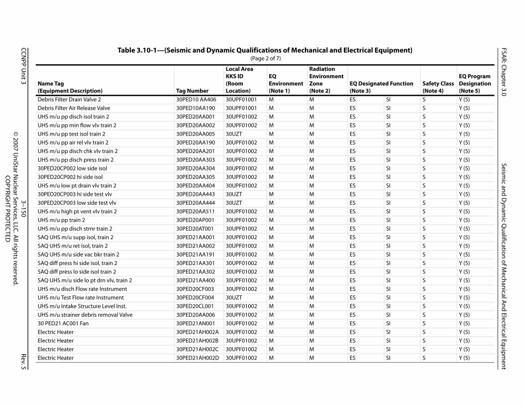
FSAR: Chapter 3.0
Seismic and D
ynamic Q
ualification of Mechanical A
nd Electrical Equipment
CCNPP U
nit 33–150
Rev.5©
2007 UniStar N
uclear Services, LLC. All rights reserved.
COPYRIG
HT PRO
TECTED
De SI S Y (5)De SI S Y (5)UH SI S Y (5)UH SI S Y (5)UH SI S Y (5)UH SI S Y (5)UH SI S Y (5)UH SI S Y (5)30 SI S Y (5)30 SI S Y (5)UH SI S Y (5)30 SI S Y (5)30 SI S Y (5)UH SI S Y (5)UH SI S Y (5)UH SI S Y (5)SA SI S Y (5)SA SI S Y (5)SA SI S Y (5)SA SI S Y (5)SA SI S Y (5)SA SI S Y (5)UH SI S Y (5)UH SI S Y (5)UH SI S Y (5)UH SI S Y (5)30 SI S Y (5)El SI S Y (5)El SI S Y (5)El SI S Y (5)El SI S Y (5)
quipment}
N(E
ated Function Safety Class(Note 4)
EQ Program Designation(Note 5)
bris Filter Drain Valve 2 30PED10 AA406 30UPF01001 M M ESbris Filter Air Release Valve 30PED10AA190 30UPF01001 M M ESS m/u pp disch isol train 2 30PED20AA001 30UPF01002 M M ESS m/u pp min flow vlv train 2 30PED20AA002 30UPF01002 M M ESS m/u pp test isol train 2 30PED20AA005 30UZT M M ESS m/u pp air rel vlv train 2 30PED20AA190 30UPF01002 M M ESS m/u pp disch chk vlv train 2 30PED20AA201 30UPF01002 M M ESS m/u pp disch press train 2 30PED20AA303 30UPF01002 M M ES
PED20CP002 low side isol 30PED20AA304 30UPF01002 M M ESPED20CP002 hi side isol 30PED20AA305 30UPF01002 M M ESS m/u low pt drain vlv train 2 30PED20AA404 30UPF01002 M M ES
PED20CP003 hi side test vlv 30PED20AA443 30UZT M M ESPED20CP003 low side test vlv 30PED20AA444 30UZT M M ESS m/u high pt vent vlv train 2 30PED20AA511 30UPF01002 M M ESS m/u pp train 2 30PED20AP001 30UPF01002 M M ESS m/u pp disch strnr train 2 30PED20AT001 30UPF01002 M M ESQ UHS m/u supp isol, train 2 30PED21AA001 30UPF01002 M M ESQ UHS m/u ret isol, train 2 30PED21AA002 30UPF01002 M M ESQ UHS m/u side vac bkr train 2 30PED21AA191 30UPF01002 M M ESQ diff press hi side isol, train 2 30PED21AA301 30UPF01002 M M ESQ diff press lo side isol train 2 30PED21AA302 30UPF01002 M M ESQ UHS m/u side lo pt drn vlv, train 2 30PED21AA400 30UPF01002 M M ESS m/u disch Flow rate Instrument 30PED20CF003 30UPF01002 M M ESS m/u Test Flow rate Instrument 30PED20CF004 30UZT M M ESS m/u Intake Structure Level Inst. 30PED20CL001 30UPF01002 M M ESS m/u strainer debris removal Valve 30PED20AA006 30UPF01002 M M ES
PED21 AC001 Fan 30PED21AN001 30UPF01002 M M ESectric Heater 30PED21AH002A 30UPF01002 M M ESectric Heater 30PED21AH002B 30UPF01002 M M ESectric Heater 30PED21AH002C 30UPF01002 M M ESectric Heater 30PED21AH002D 30UPF01002 M M ES
Table 3.10-1—{Seismic and Dynamic Qualifications of Mechanical and Electrical E (Page 2 of 7)
ame Tagquipment Description) Tag Number
Local AreaKKS ID(RoomLocation)
EQEnvironment(Note 1)
RadiationEnvironmentZone(Note 2)
EQ Design(Note 3)

FSAR: Chapter 3.0
Seismic and D
ynamic Q
ualification of Mechanical A
nd Electrical Equipment
CCNPP U
nit 33–151
Rev.5©
2007 UniStar N
uclear Services, LLC. All rights reserved.
COPYRIG
HT PRO
TECTED
De SI S Y (5)De SI S Y (5)De SI S Y (5)UH SI S Y (5)UH SI S Y (5)UH SI S Y (5)UH SI S Y (5)UH SI S Y (5)UH SI S Y (5)30 SI S Y (5)30 SI S Y (5)UH SI S Y (5)30 SI S Y (5)30 SI S Y (5)UH SI S Y (5)UH SI S Y (5)UH SI S Y (5)SA SI S Y (5)SA SI S Y (5)SA SI S Y (5)SA SI S Y (5)SA SI S Y (5)SA SI S Y (5)UH SI S Y (5)UH SI S Y (5)UH SI S Y (5)UH SI S Y (5)30 SI S Y (5)El SI S Y (5)El SI S Y (5)El SI S Y (5)
quipment}
N(E
ated Function Safety Class(Note 4)
EQ Program Designation(Note 5)
bris Filter Drain Valve 1 30PED20 AA405 30UPF01002 M M ESbris Filter Drain Valve 2 30PED20 AA406 30UPF01002 M M ESbris Filter Air Release Valve 30PED20AA190 30UPF01002 M M ESS m/u pp disch isol train 3 30PED30AA001 30UPF01003 M M ESS m/u pp min flow vlv train 3 30PED30AA002 30UPF01003 M M ESS m/u pp test isol train 3 30PED30AA005 30UZT M M ESS m/u pp air rel vlv train 3 30PED30AA190 30UPF01003 M M ESS m/u pp disch chk vlv train 3 30PED30AA201 30UPF01003 M M ESS m/u pp disch press train 3 30PED30AA303 30UPF01003 M M ES
PED30CP002 low side isol 30PED30AA304 30UPF01003 M M ESPED30CP002 hi side isol 30PED30AA305 30UPF01003 M M ESS m/u low pt drain vlv train 3 30PED30AA404 30UPF01003 M M ES
PED30CP003 hi side test vlv 30PED30AA443 30UZT M M ESPED30CP003 low side test vlv 30PED30AA444 30UZT M M ESS m/u high pt vent vlv train 3 30PED30AA511 30UPF01003 M M ESS m/u pp train 3 30PED30AP001 30UPF01003 M M ESS m/u pp disch strnr train 3 30PED30AT001 30UPF01003 M M ESQ UHS m/u supp isol, train 3 30PED31AA001 30UPF01003 M M ESQ UHS m/u ret isol, train 3 30PED31AA002 30UPF01003 M M ESQ UHS m/u side vac bkr train 3 30PED31AA191 30UPF01003 M M ESQ diff press hi side isol, train 3 30PED31AA301 30UPF01003 M M ESQ diff press lo side isol train 3 30PED31AA302 30UPF01003 M M ESQ UHS m/u side lo pt drn vlv, train 3 30PED31AA400 30UPF01003 M M ESS m/u disch Flow rate Instrument 30PED30CF003 30UPF01003 M M ESS m/u Test Flow rate Instrument 30PED30CF004 30UZT M M ESS m/u Intake Structure Level Inst. 30PED30CL001 30UPF01003 M M ESS m/u strainer debris removal Valve 30PED30AA006 30UPF01003 M M ES
PED31 AC001 Fan 30PED31AN001 30UPF01003 M M ESectric Heater 30PED31AH002A 30UPF01003 M M ESectric Heater 30PED31AH002B 30UPF01003 M M ESectric Heater 30PED31AH002C 30UPF01003 M M ES
Table 3.10-1—{Seismic and Dynamic Qualifications of Mechanical and Electrical E (Page 3 of 7)
ame Tagquipment Description) Tag Number
Local AreaKKS ID(RoomLocation)
EQEnvironment(Note 1)
RadiationEnvironmentZone(Note 2)
EQ Design(Note 3)

FSAR: Chapter 3.0
Seismic and D
ynamic Q
ualification of Mechanical A
nd Electrical Equipment
CCNPP U
nit 33–152
Rev.5©
2007 UniStar N
uclear Services, LLC. All rights reserved.
COPYRIG
HT PRO
TECTED
El SI S Y (5)De SI S Y (5)De SI S Y (5)De SI S Y (5)UH SI S Y (5)UH SI S Y (5)UH SI S Y (5)UH SI S Y (5)UH SI S Y (5)UH SI S Y (5)30 SI S Y (5)30 SI S Y (5)UH SI S Y (5)30 SI S Y (5)30 SI S Y (5)UH SI S Y (5)UH SI S Y (5)UH SI S Y (5)SA SI S Y (5)SA SI S Y (5)SA SI S Y (5)SA SI S Y (5)SA SI S Y (5)SA SI S Y (5)UH SI S Y (5)UH SI S Y (5)UH SI S Y (5)UH SI S Y (5)30 SI S Y (5)El SI S Y (5)El SI S Y (5)
quipment}
N(E
ated Function Safety Class(Note 4)
EQ Program Designation(Note 5)
ectric Heater 30PED31AH002D 30UPF01003 M M ESbris Filter Drain Valve 1 30PED30 AA405 30UPF01003 M M ESbris Filter Drain Valve 2 30PED30 AA406 30UPF01003 M M ESbris Filter Air Release Valve 30PED30AA190 30UPF01003 M M ESS m/u pp disch isol train 4 30PED40AA001 30UPF01004 M M ESS m/u pp min flow vlv train 4 30PED40AA002 30UPF01004 M M ESS m/u pp test isol train 4 30PED40AA005 30UZT M M ESS m/u pp air rel vlv train 4 30PED40AA190 30UPF01004 M M ESS m/u pp disch chk vlv train 4 30PED40AA201 30UPF01004 M M ESS m/u pp disch press train 4 30PED40AA303 30UPF01004 M M ES
PED40CP002 low side isol 30PED40AA304 30UPF01004 M M ESPED40CP002 hi side isol 30PED40AA305 30UPF01004 M M ESS m/u low pt drain vlv train 4 30PED40AA404 30UPF01004 M M ES
PED40CP003 hi side test vlv 30PED40AA443 30UZT M M ESPED40CP003 low side test vlv 30PED40AA444 30UZT M M ESS m/u high pt vent vlv train 4 30PED40AA511 30UPF01004 M M ESS m/u pp train 4 30PED40AP001 30UPF01004 M M ESS m/u pp disch strnr train 4 30PED40AT001 30UPF01004 M M ESQ UHS m/u supp isol, train 4 30PED41AA001 30UPF01004 M M ESQ UHS m/u ret isol, train 4 30PED41AA002 30UPF01004 M M ESQ UHS m/u side vac bkr train 4 30PED41AA191 30UPF01004 M M ESQ diff press hi side isol, train 4 30PED41AA301 30UPF01004 M M ESQ diff press lo side isol train 4 30PED41AA302 30UPF01004 M M ESQ UHS m/u side lo pt drn vlv, train 4 30PED41AA400 30UPF01004 M M ESS m/u disch Flow rate Instrument 30PED40CF003 30UPF01004 M M ESS m/u Test Flow rate Instrument 30PED40CF004 30UZT M M ESS m/u Intake Structure Level Inst. 30PED40CL001 30UPF01004 M M ESS m/u strainer debris removal Valve 30PED40AA006 30UPF01004 M M ES
PED41 AC001 Fan 30PED41AN001 30UPF01004 M M ESectric Heater 30PED41AH002A 30UPF01004 M M ESectric Heater 30PED41AH002B 30UPF01004 M M ES
Table 3.10-1—{Seismic and Dynamic Qualifications of Mechanical and Electrical E (Page 4 of 7)
ame Tagquipment Description) Tag Number
Local AreaKKS ID(RoomLocation)
EQEnvironment(Note 1)
RadiationEnvironmentZone(Note 2)
EQ Design(Note 3)

FSAR: Chapter 3.0
Seismic and D
ynamic Q
ualification of Mechanical A
nd Electrical Equipment
CCNPP U
nit 33–153
Rev.5©
2007 UniStar N
uclear Services, LLC. All rights reserved.
COPYRIG
HT PRO
TECTED
El SI S Y (5)El SI S Y (5)De SI S Y (5)De SI S Y (5)De SI S Y (5)30 SI S Y (5)30 SI S Y (5)30 SI S Y (5)30 SI S Y (5)UH SI S Y (5)UH SI S Y (5)UH SI S Y (5)UH SII NS-AQ Y (5)UH SI S Y (5)UH SI S Y (5)UH SI S Y (5)SA SI S Y (5)30 SI S Y (5)30 SI S Y (5)30 SI S Y (5)30 SI S Y (5)UH SI S Y (5)UH SI S Y (5)UH SI S Y (5)30 SI S Y (5)UH SII NS-AQ Y (5)UH SI S Y (5)UH SI S Y (5)UH SI S Y (5)30 SI S Y (5)SA SI S Y (5)
quipment}
N(E
ated Function Safety Class(Note 4)
EQ Program Designation(Note 5)
ectric Heater 30PED41AH002C 30UPF01004 M M ESectric Heater 30PED41AH002D 30UPF01004 M M ES
bris Filter Drain Valve 1 30PED40 AA405 30UPF01004 M M ESbris Filter Drain Valve 2 30PED40 AA406 30UPF01004 M M ESbris Filter Air Release Valve 30PED40AA190 30UPF01004 M M ESPED10AA001 valve motor actuator 30PED10AA001 30UPF01001 M M ESPED10AA002 valve motor actuator 30PED10AA002 30UPF01001 M M ESPED10AA005 valve motor actuator 30PED10AA005 30UPF01001 M M ESPED10AA006 valve motor actuator 30PED10AA006 30UPF01001 M M ESS m/u pp motor heater, train 1 30PED10AH001 30UPF01001 M M ESS m/u pp motor, train 1 30PED10AP001 30UPF01001 M M ESS m/u pp disch strnr actuator, train1 30PED10AT001 30UPF01001 M M ESS m/u pp test flow, train 1 30PED10CF002 30UZT M MS m/u pp disch press, train 1 30PED10CP001 30UPF01001 M M ESS m/u strnr diff press, train 1 30PED10CP002 30UPF01001 M M ESS m/u pp disch temp, train 1 30PED10CT001 30UPF01001 M M ESQ UHS m/u diff press inst, train 1 30PED11CP501 30UPF01001 M M ESPED11 AC001 Fan motor 30PED11AN001 30UPF01001 M M ESPED20AA001 valve motor actuator 30PED20AA001 30UPF01002 M M ESPED20AA002 valve motor actuator 30PED20AA002 30UPF01002 M M ESPED20AA005 valve motor actuator 30PED20AA005 30UPF01002 M M ESS m/u pp motor heater, train 2 30PED20AH001 30UPF01002 M M ESS m/u pp motor, train 2 30PED20AP001 30UPF01002 M M ESS m/u pp disch strnr actuator, train2 30PED20AT001 30UPF01002 M M ES
PED20AA006 valve motor actuator 30PED20AA006 30UPF01002 M M ESS m/u pp test flow, train 2 30PED20CF002 30UZT M MS m/u pp disch press, train 2 30PED20CP001 30UPF01002 M M ESS m/u strnr diff press, train 2 30PED20CP002 30UPF01002 M M ESS m/u pp disch temp, train 2 30PED20CT001 30UPF01002 M M ES
PED21 AC001 Fan motor 30PED21AN001 30UPF01002 M M ESQ UHS m/u diff press inst, train 2 30PED21CP501 30UPF01002 M M ES
Table 3.10-1—{Seismic and Dynamic Qualifications of Mechanical and Electrical E (Page 5 of 7)
ame Tagquipment Description) Tag Number
Local AreaKKS ID(RoomLocation)
EQEnvironment(Note 1)
RadiationEnvironmentZone(Note 2)
EQ Design(Note 3)
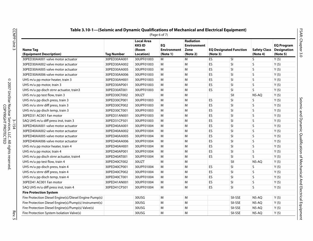
FSAR: Chapter 3.0
Seismic and D
ynamic Q
ualification of Mechanical A
nd Electrical Equipment
CCNPP U
nit 33–154
Rev.5©
2007 UniStar N
uclear Services, LLC. All rights reserved.
COPYRIG
HT PRO
TECTED
30 SI S Y (5)30 SI S Y (5)30 SI S Y (5)30 SI S Y (5)UH SI S Y (5)UH SI S Y (5)UH SI S Y (5)UH SII NS-AQ Y (5)UH SI S Y (5)UH SI S Y (5)UH SI S Y (5)30 SI S Y (5)SA SI S Y (5)30 SI S Y (5)30 SI S Y (5)30 SI S Y (5)30 SI S Y (5)UH SI S Y (5)UH SI S Y (5)UH SI S Y (5)UH SII NS-AQ Y (5)UH SI S Y (5)UH SI S Y (5)UH SI S Y (5)30 SI S Y (5)SA SI S Y (5)FiFi SII-SSE NS-AQ Y (5)Fi SII-SSE NS-AQ Y (5)Fi SII-SSE NS-AQ Y (5)Fi SII-SSE NS-AQ Y (5)
quipment}
N(E
ated Function Safety Class(Note 4)
EQ Program Designation(Note 5)
PED30AA001 valve motor actuator 30PED30AA001 30UPF01003 M M ESPED30AA002 valve motor actuator 30PED30AA002 30UPF01003 M M ESPED30AA005 valve motor actuator 30PED30AA005 30UPF01003 M M ESPED30AA006 valve motor actuator 30PED30AA006 30UPF01003 M M ESS m/u pp motor heater, train 3 30PED30AH001 30UPF01003 M M ESS m/u pp motor, train 3 30PED30AP001 30UPF01003 M M ESS m/u pp disch strnr actuator, train3 30PED30AT001 30UPF01003 M M ESS m/u pp test flow, train 3 30PED30CF002 30UZT M MS m/u pp disch press, train 3 30PED30CP001 30UPF01003 M M ESS m/u strnr diff press, train 3 30PED30CP002 30UPF01003 M M ESS m/u pp disch temp, train 3 30PED30CT001 30UPF01003 M M ES
PED31 AC001 Fan motor 30PED31AN001 30UPF01003 M M ESQ UHS m/u diff press inst, train 3 30PED31CP501 30UPF01003 M M ESPED40AA001 valve motor actuator 30PED40AA001 30UPF01004 M M ESPED40AA002 valve motor actuator 30PED40AA002 30UPF01004 M M ESPED40AA005 valve motor actuator 30PED40AA005 30UPF01004 M M ESPED40AA006 valve motor actuator 30PED40AA006 30UPF01004 M M ESS m/u pp motor heater, train 4 30PED40AH001 30UPF01004 M M ESS m/u pp motor, train 4 30PED40AP001 30UPF01004 M M ESS m/u pp disch strnr actuator, train4 30PED40AT001 30UPF01004 M M ESS m/u pp test flow, train 4 30PED40CF002 30UZT M MS m/u pp disch press, train 4 30PED40CP001 30UPF01004 M M ESS m/u strnr diff press, train 4 30PED40CP002 30UPF01004 M M ESS m/u pp disch temp, train 4 30PED40CT001 30UPF01004 M M ES
PED41 AC001 Fan motor 30PED41AN001 30UPF01004 M M ESQ UHS m/u diff press inst, train 4 30PED41CP501 30UPF01004 M M ES
re Protection Systemre Protection Diesel Engine(s)/Diesel Engine Pump(s) 30USG M Mre Protection Diesel Engine(s)/Pump(s) Instrument(s) 30USG M Mre Protection Diesel Engine(s)/Pump(s) Valve(s) 30USG M Mre Protection System Isolation Valve(s) 30USG M M
Table 3.10-1—{Seismic and Dynamic Qualifications of Mechanical and Electrical E (Page 6 of 7)
ame Tagquipment Description) Tag Number
Local AreaKKS ID(RoomLocation)
EQEnvironment(Note 1)
RadiationEnvironmentZone(Note 2)
EQ Design(Note 3)

FSAR: Chapter 3.0
Seismic and D
ynamic Q
ualification of Mechanical A
nd Electrical Equipment
CCNPP U
nit 33–155
Rev.5©
2007 UniStar N
uclear Services, LLC. All rights reserved.
COPYRIG
HT PRO
TECTED
Fi SII-SSE NS-AQ Y (5)Fi SII-SSE NS-AQ Y (5)Fi SII-SSE NS-AQ Y (5)Fi SII-SSE NS-AQ Y (5)Fi SII-SSE NS-AQ Y (5)Hy SII-SSE NS-AQ Y (5)UH SII-SSE NS-AQ Y (5)Cl31 SI S Y (5)32 SI S Y (5)33 SI S Y (5)34 SI S Y (5)31 SI S Y (5)32 SI S Y (5)33 SI S Y (5)34 SI S Y (5)
No1.2.3. tion System piping, valves, and equipment su E))4. netic Compatibility), C/NM (Consumables/ Non M5. les, Yes (5) = EQ Seismic, Yes (6) = EQ EMC.
quipment}
N(E
ated Function Safety Class(Note 4)
EQ Program Designation(Note 5)
re Protection System Check Valve(s) 30USG M Mre Protection System Pressure Relief Valve(s) 30USG M Mre Protection Water Storage Tanks Isolation Valve(s) M Mre Protection System Post Indicator Valve(s) 30UZT M Mre Protection System Hydrant Isolation Valve(s) 30UZT M M
drants Supplying Protection to SSE Buildings 30UZT M MS Makeup Water Intake Structure Hose Station(s) 30UPF M M
ass 1E Emergency Power Supply (EPSS) BMT05 6.9 kV to 480 V (XFMR) 31BMT05GT0 M M ESBMT05 6.9 kV to 480 V (XFMR) 32BMT05GT0 M M ESBMT05 6.9 kV to 480 V (XFMR) 33BMT05GT0 M M ESBMT05 6.9 kV to 480 V (XFMR) 34BMT05GT0 M M ESBNG 1E 480 V Bus (MCC) 31BNG01GW0 M M ESBNG 1E 480 V Bus (MCC) 32BNG01GW0 M M ESBNG 1E 480 V Bus (MCC) 33BNG01GW0 M M ESBNG 1E 480 V Bus (MCC) 34BNG01GW0 M M ES
tes: EQ Environment (M= Mild, H= Harsh) Radiation Environment Zone (M= Mild, H= Harsh) RT (Reactor Trip), ES (Engineered Safeguards), PAM (Postaccident Monitoring), SI (Seismic I), SII (Seismic II), SII-SSE (Seismic II- Fire Protecpplying fire suppression water to systems required for safe shutdown are required to operate following a Safe Shutdown Earthquake (SS
Safety Class: S (Safety-Related (i.e., QA Level I)), NS-AQ (Supplemental Grade Non-Safety (i.e., QA Level II)), 1E (Class 1E), EMC (Electromagetalics) Yes (1) = Full EQ Electrical, Yes (2) = EQ Radiation Harsh-Electrical, Yes (3) = EQ Radiation Harsh-Consumables, Yes (4) = EQ for Consumab
Table 3.10-1—{Seismic and Dynamic Qualifications of Mechanical and Electrical E (Page 7 of 7)
ame Tagquipment Description) Tag Number
Local AreaKKS ID(RoomLocation)
EQEnvironment(Note 1)
RadiationEnvironmentZone(Note 2)
EQ Design(Note 3)
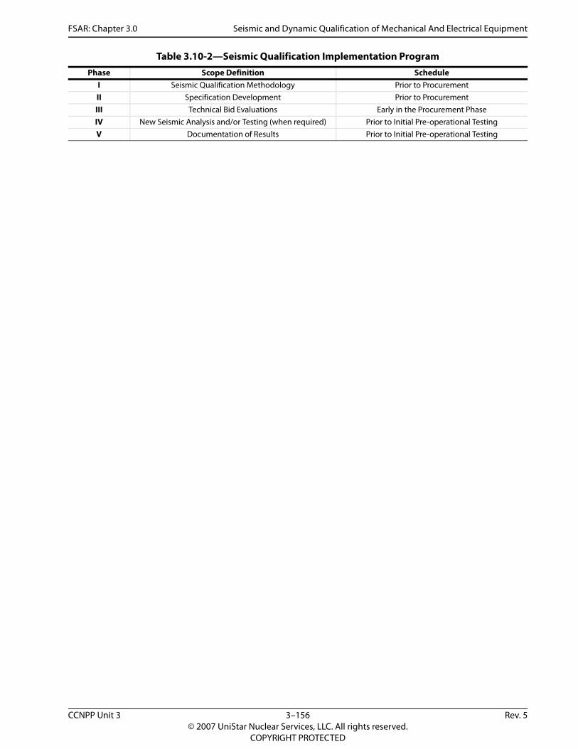
FSAR: Chapter 3.0 Seismic and Dynamic Qualification of Mechanical And Electrical Equipment
Table 3.10-2—Seismic Qualification Implementation ProgramPhase Scope Definition Schedule
I Seismic Qualification Methodology Prior to Procurement II Specification Development Prior to ProcurementIII Technical Bid Evaluations Early in the Procurement PhaseIV New Seismic Analysis and/or Testing (when required) Prior to Initial Pre-operational TestingV Documentation of Results Prior to Initial Pre-operational Testing
CCNPP Unit 3 3–156 Rev. 5© 2007 UniStar Nuclear Services, LLC. All rights reserved.
COPYRIGHT PROTECTED

FSAR: Chapter 3.0 Environmental Qualification Of Mechanical And Electrical Equipment
3.11 ENVIRONMENTAL QUALIFICATION OF MECHANICAL AND ELECTRICAL EQUIPMENT
This section of the U.S. EPR FSAR is incorporated by reference with the supplements as described in the following sections.
The U.S. EPR FSAR includes the following COL Holder Item in Section 3.11:
A COL applicant that references the U.S EPR design certification will maintain the equipment qualification test results and qualification status file during the equipment selection, procurement phase and throughout the installed life in the plant.
This COL Holder Item is addressed as follows:
{Constellation Generation Group and UniStar Nuclear Operating Services} shall maintain the equipment qualification test results and qualification status file during the equipment selection, procurement phase and throughout the installed life in the plant.Calvert Cliffs 3 Nuclear Project, LLC and UniStar Nuclear Operating Services, LLC} shall develop and maintain 1) a list of electrical equipment meeting the criteria of 10 CFR 50.49 and 2) a record of qualification for each applicable electrical equipment type. The record shall contain the necessary environmental qualification information to meet the requirements of 10 CFR 50.49. This information will be stored and retained in accordance with the Quality Assurance Program Description or QAPD. This information will remain current and in an auditable form that meets requirements of 10 CFR 50.49(j) and the QAPD.
3.11.1 EQUIPMENT IDENTIFICATION AND ENVIRONMENTAL CONDITIONS
No departures or supplements.
3.11.1.1 Equipment Identification
No departures or supplements.
3.11.1.1.1 Nuclear Island
No departures or supplements.
3.11.1.1.2 Balance of Plant (BOP) and Turbine Island (TI)
No departures or supplements.
3.11.1.1.3 Equipment Review and Screening
The U.S. EPR FSAR includes the following COL Item in Section 3.11.1.1.3:
A COL applicant that references the U. S. EPR design certification will identify additional site-specific components that need to be added to the environmental qualification list in Table 3.11-1.
This COL Item is addressed as follows:
Table 3.11-1 provides the list of additional site-specific components to add to the equipment list in U.S. EPR FSAR Table 3.11-1. {It includes the safety-related and augmented quality items of the site-specific portion of the UHS Makeup Water System and Fire Protection System.} The cable types listed are typical of those which are anticipated to be utilized throughout the plant in safety-related applications, including those which are site-specific. However, the function
CCNPP Unit 3 3–157 Rev. 5© 2007 UniStar Nuclear Services, LLC. All rights reserved.
COPYRIGHT PROTECTED
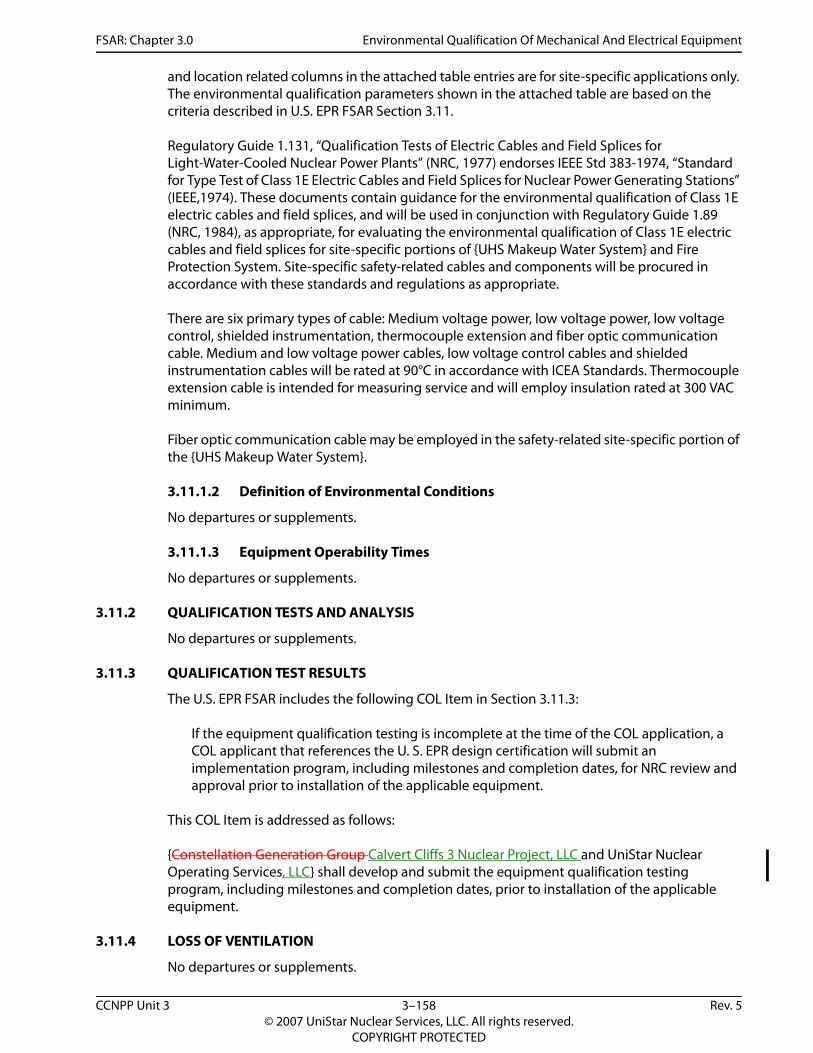
FSAR: Chapter 3.0 Environmental Qualification Of Mechanical And Electrical Equipment
and location related columns in the attached table entries are for site-specific applications only. The environmental qualification parameters shown in the attached table are based on the criteria described in U.S. EPR FSAR Section 3.11.
Regulatory Guide 1.131, “Qualification Tests of Electric Cables and Field Splices for Light-Water-Cooled Nuclear Power Plants” (NRC, 1977) endorses IEEE Std 383-1974, “Standard for Type Test of Class 1E Electric Cables and Field Splices for Nuclear Power Generating Stations” (IEEE,1974). These documents contain guidance for the environmental qualification of Class 1E electric cables and field splices, and will be used in conjunction with Regulatory Guide 1.89 (NRC, 1984), as appropriate, for evaluating the environmental qualification of Class 1E electric cables and field splices for site-specific portions of {UHS Makeup Water System} and Fire Protection System. Site-specific safety-related cables and components will be procured in accordance with these standards and regulations as appropriate.
There are six primary types of cable: Medium voltage power, low voltage power, low voltage control, shielded instrumentation, thermocouple extension and fiber optic communication cable. Medium and low voltage power cables, low voltage control cables and shielded instrumentation cables will be rated at 90°C in accordance with ICEA Standards. Thermocouple extension cable is intended for measuring service and will employ insulation rated at 300 VAC minimum.
Fiber optic communication cable may be employed in the safety-related site-specific portion of the {UHS Makeup Water System}.
3.11.1.2 Definition of Environmental Conditions
No departures or supplements.
3.11.1.3 Equipment Operability Times
No departures or supplements.
3.11.2 QUALIFICATION TESTS AND ANALYSIS
No departures or supplements.
3.11.3 QUALIFICATION TEST RESULTS
The U.S. EPR FSAR includes the following COL Item in Section 3.11.3:
If the equipment qualification testing is incomplete at the time of the COL application, a COL applicant that references the U. S. EPR design certification will submit an implementation program, including milestones and completion dates, for NRC review and approval prior to installation of the applicable equipment.
This COL Item is addressed as follows:
{Constellation Generation Group Calvert Cliffs 3 Nuclear Project, LLC and UniStar Nuclear Operating Services, LLC} shall develop and submit the equipment qualification testing program, including milestones and completion dates, prior to installation of the applicable equipment.
3.11.4 LOSS OF VENTILATION
No departures or supplements.
CCNPP Unit 3 3–158 Rev. 5© 2007 UniStar Nuclear Services, LLC. All rights reserved.
COPYRIGHT PROTECTED

FSAR: Chapter 3.0 Environmental Qualification Of Mechanical And Electrical Equipment
3.11.5 ESTIMATED CHEMICAL AND RADIATION ENVIRONMENT
No departures or supplements.
3.11.6 QUALIFICATION OF MECHANICAL EQUIPMENT
No departures or supplements.
3.11.7 REFERENCES
{IEEE, 1974. Standard for Type Test of Class 1E Electric Cables and Field Splices for Nuclear Power Generating Stations, IEEE Std 383-1974, IEEE, 1974.
NRC, 1977. Qualification Tests of Electric Cables and Field Splices and Connections for Light-Water-Cooled Nuclear Power Plants, Regulatory Guide 1.131, U.S. Nuclear Regulatory Commission, August 1977.
NRC, 1984. Environmental Qualification of Certain Electric Equipment Important to Safety for Nuclear Power Plants, Regulatory Guide 1.89, Revision 1, U.S. Nuclear Regulatory Commission, June 1984.}
CCNPP Unit 3 3–159 Rev. 5© 2007 UniStar Nuclear Services, LLC. All rights reserved.
COPYRIGHT PROTECTED

FSAR: Chapter 3.0
Environmental Q
ualification Of M
echanical And Electrical Equipm
ent
CCNPP U
nit 33–160
Rev.5©
2007 UniStar N
uclear Services, LLC. All rights reserved.
COPYRIG
HT PRO
TECTED
ment}
Safety Class (Note 4)
EQ Program Designation
(Note 5)U30ac
S 1E EMC Y(5) Y(6)
30ac
S 1E EMC Y(5) Y(6)
30ac
S 1E EMC Y(5) Y(6)
30ac
S 1E EMC Y(5) Y(6)
UHhe
S 1E Y(5) Y(6)
UHtra
S 1E EMC Y(5) Y(6)
UHac
S 1E EMC Y(5) Y(6)
UHtra
NS-AQ EMC Y(5) Y(6)
UHtra
S 1E EMC Y(5) Y(6)
UHtra
S 1E EMC Y(5) Y(6)
UHte
S 1E EMC Y(5) Y(6)
SAin
S 1E EMC Y(5) Y(6)
30 S 1E EMC Y(5) Y(6)30ac
S 1E EMC Y(5) Y(6)
30ac
S 1E EMC Y(5) Y(6)
30ac
S 1E EMC Y(5) Y(6)
UHhe
S 1E Y(5) Y(6)
Table 3.11-1—{Site-Specific Environmentally Qualified Electrical/I&C Equip (Page 1 of 5)
Name Tag (Equipment Description) Tag Number
Local Area KKS ID (Room Location)
EQEnvironment
(Note 1)
RadiationEnvironment
Zone (Note 2)
EQ Designated Function (Note 3)
HS Makeup Water System PED10AA001 valve motor tuator
30PED10AA001 30UPF01001 M M ES SI
PED10AA002 valve motor tuator
30PED10AA002 30UPF01001 M M ES SI
PED10AA005 valve motor tuator
30PED10AA005 30UPF01001 M M ES SI
PED10AA006 valve motor tuator
30PED10AA006 30UPF01001 M M ES SI
S makeup /u pp motor ater, train 1
30PED10AH001 30UPF01001 M M ES SI
S makeup /u pp motor, in 1
30PED10AP001 30UPF01001 M M ES SI
S makeup /u pp disch strnr tuator, train1
30PED10AT001 30UPF01001 M M ES SI
S makeup /u pp test flow, in 1
30PED10CF002 30UZT M M SII
S makeup /u pp disch press, in 1
30PED10CP001 30UPF01001 M M ES SI
S makeup strnr diff press, in 1
30PED10CP002 30UPF01001 M M ES SI
S makeup m/u pp disch mp, train 1
30PED10CT001 30UPF01001 M M ES SI
Q UHS makeup diff press st, train 1
30PED11CP501 30UPF01001 M M ES SI
PED11 AC001 Fan motor 30PED11AN001 30UPF01001 M M ES SIPED20AA001 valve motor tuator
30PED20AA001 30UPF01002 M M ES SI
PED20AA002 valve motor tuator
30PED20AA002 30UPF01002 M M ES SI
PED20AA005 valve motor tuator
30PED20AA005 30UPF01002 M M ES SI
S makeup /u pp motor ater, train 2
30PED20AH001 30UPF01002 M M ES SI

FSAR: Chapter 3.0
Environmental Q
ualification Of M
echanical And Electrical Equipm
ent
CCNPP U
nit 33–161
Rev.5©
2007 UniStar N
uclear Services, LLC. All rights reserved.
COPYRIG
HT PRO
TECTED
UHtra
S 1E EMC Y(5) Y(6)
UHac
S 1E EMC Y(5) Y(6)
30ac
S 1E EMC Y(5) Y(6)
UHtra
NS-AQ EMC Y(5) Y(6)
UHtra
S 1E EMC Y(5) Y(6)
UHtra
S 1E EMC Y(5) Y(6)
UHtra
S 1E EMC Y(5) Y(6)
30 S 1E EMC Y(5) Y(6)SAin
S 1E EMC Y(5) Y(6)
30ac
S 1E EMC Y(5) Y(6)
30ac
S 1E EMC Y(5) Y(6)
30ac
S 1E EMC Y(5) Y(6)
30ac
S 1E EMC Y(5) Y(6)
UHhe
S 1E Y(5) Y(6)
UHtra
S 1E EMC Y(5) Y(6)
UHac
S 1E EMC Y(5) Y(6)
UHtra
NS-AQ EMC Y(5) Y(6)
UHtra
S 1E EMC Y(5) Y(6)
ment}
Safety Class (Note 4)
EQ Program Designation
(Note 5)
S makeup /u pp motor, in 230PED20AP001 30UPF01002 M M ES SI
S makeup /u pp disch strnr tuator, train2
30PED20AT001 30UPF01002 M M ES SI
PED20AA006 valve motor tuator
30PED20AA006 30UPF01002 M M ES SI
S makeup /u pp test flow, in 2
30PED20CF002 30UZT M M SII
S makeup /u pp disch press, in 2
30PED20CP001 30UPF01002 M M ES SI
S makeup strnr diff press, in 2
30PED20CP002 30UPF01002 M M ES SI
S makeup /u pp disch temp, in 2
30PED20CT001 30UPF01002 M M ES SI
PED21 AC001 Fan motor 30PED21AN001 30UPF01002 M M ES SIQ UHS makeup diff press
st, train 230PED21CP501 30UPF01002 M M ES SI
PED30AA001 valve motor tuator
30PED30AA001 30UPF01003 M M ES SI
PED30AA002 valve motor tuator
30PED30AA002 30UPF01003 M M ES SI
PED30AA005 valve motor tuator
30PED30AA005 30UPF01003 M M ES SI
PED30AA006 valve motor tuator
30PED30AA006 30UPF01003 M M ES SI
S makeup /u pp motor ater, train 3
30PED30AH001 30UPF01003 M M ES SI
S makeup /u pp motor, in 3
30PED30AP001 30UPF01003 M M ES SI
S makeup /u pp disch strnr tuator, train3
30PED30AT001 30UPF01003 M M ES SI
S makeup /u pp test flow, in 3
30PED30CF002 30UZT M M SII
S makeup /u pp disch press, in 3
30PED30CP001 30UPF01003 M M ES SI
Table 3.11-1—{Site-Specific Environmentally Qualified Electrical/I&C Equip (Page 2 of 5)
Name Tag (Equipment Description) Tag Number
Local Area KKS ID (Room Location)
EQEnvironment
(Note 1)
RadiationEnvironment
Zone (Note 2)
EQ Designated Function (Note 3)
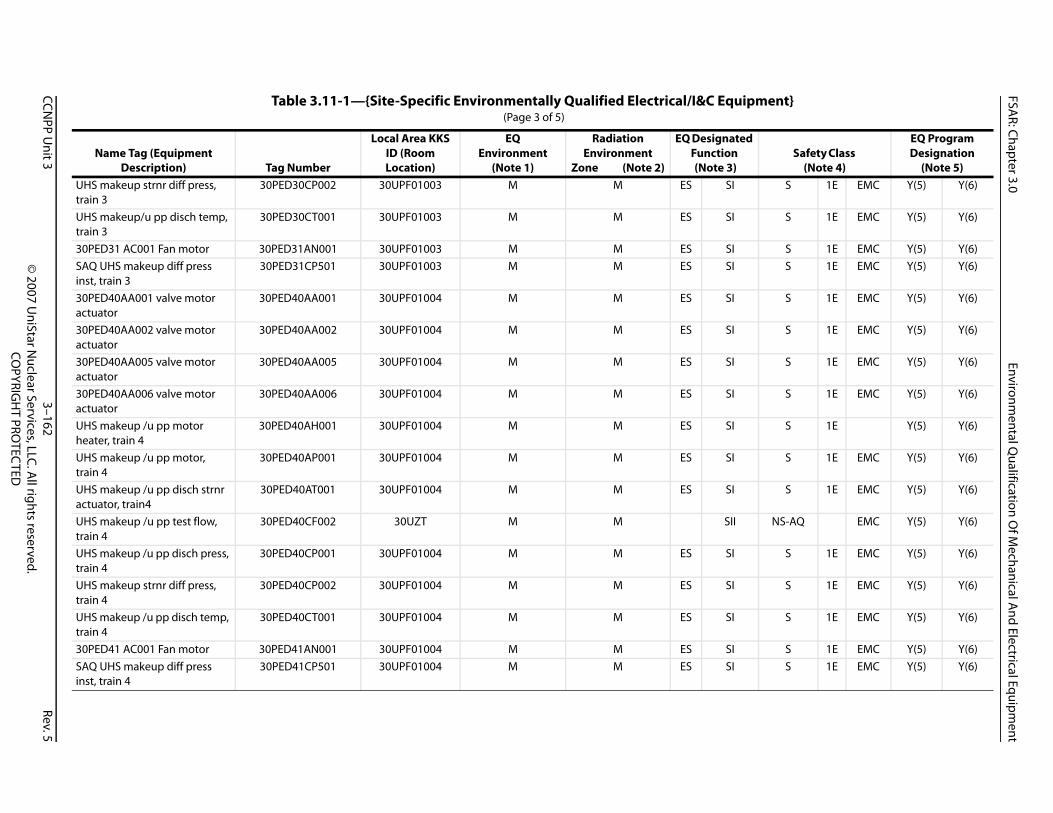
FSAR: Chapter 3.0
Environmental Q
ualification Of M
echanical And Electrical Equipm
ent
CCNPP U
nit 33–162
Rev.5©
2007 UniStar N
uclear Services, LLC. All rights reserved.
COPYRIG
HT PRO
TECTED
UHtra
S 1E EMC Y(5) Y(6)
UHtra
S 1E EMC Y(5) Y(6)
30 S 1E EMC Y(5) Y(6)SAin
S 1E EMC Y(5) Y(6)
30ac
S 1E EMC Y(5) Y(6)
30ac
S 1E EMC Y(5) Y(6)
30ac
S 1E EMC Y(5) Y(6)
30ac
S 1E EMC Y(5) Y(6)
UHhe
S 1E Y(5) Y(6)
UHtra
S 1E EMC Y(5) Y(6)
UHac
S 1E EMC Y(5) Y(6)
UHtra
NS-AQ EMC Y(5) Y(6)
UHtra
S 1E EMC Y(5) Y(6)
UHtra
S 1E EMC Y(5) Y(6)
UHtra
S 1E EMC Y(5) Y(6)
30 S 1E EMC Y(5) Y(6)SAin
S 1E EMC Y(5) Y(6)
ment}
Safety Class (Note 4)
EQ Program Designation
(Note 5)
S makeup strnr diff press, in 330PED30CP002 30UPF01003 M M ES SI
S makeup/u pp disch temp, in 3
30PED30CT001 30UPF01003 M M ES SI
PED31 AC001 Fan motor 30PED31AN001 30UPF01003 M M ES SIQ UHS makeup diff press
st, train 330PED31CP501 30UPF01003 M M ES SI
PED40AA001 valve motor tuator
30PED40AA001 30UPF01004 M M ES SI
PED40AA002 valve motor tuator
30PED40AA002 30UPF01004 M M ES SI
PED40AA005 valve motor tuator
30PED40AA005 30UPF01004 M M ES SI
PED40AA006 valve motor tuator
30PED40AA006 30UPF01004 M M ES SI
S makeup /u pp motor ater, train 4
30PED40AH001 30UPF01004 M M ES SI
S makeup /u pp motor, in 4
30PED40AP001 30UPF01004 M M ES SI
S makeup /u pp disch strnr tuator, train4
30PED40AT001 30UPF01004 M M ES SI
S makeup /u pp test flow, in 4
30PED40CF002 30UZT M M SII
S makeup /u pp disch press, in 4
30PED40CP001 30UPF01004 M M ES SI
S makeup strnr diff press, in 4
30PED40CP002 30UPF01004 M M ES SI
S makeup /u pp disch temp, in 4
30PED40CT001 30UPF01004 M M ES SI
PED41 AC001 Fan motor 30PED41AN001 30UPF01004 M M ES SIQ UHS makeup diff press
st, train 430PED41CP501 30UPF01004 M M ES SI
Table 3.11-1—{Site-Specific Environmentally Qualified Electrical/I&C Equip (Page 3 of 5)
Name Tag (Equipment Description) Tag Number
Local Area KKS ID (Room Location)
EQEnvironment
(Note 1)
RadiationEnvironment
Zone (Note 2)
EQ Designated Function (Note 3)
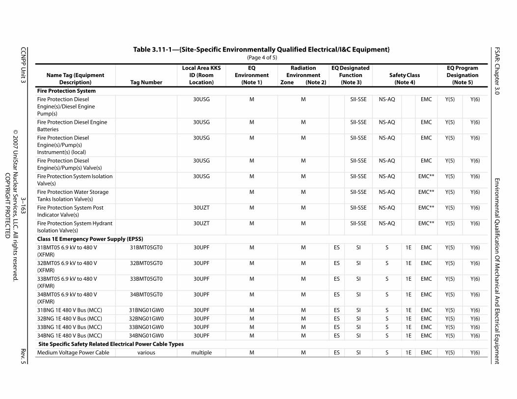
FSAR: Chapter 3.0
Environmental Q
ualification Of M
echanical And Electrical Equipm
ent
CCNPP U
nit 33–163
Rev.5©
2007 UniStar N
uclear Services, LLC. All rights reserved.
COPYRIG
HT PRO
TECTED
FiFiEnPu
NS-AQ EMC Y(5) Y(6)
FiBa
NS-AQ EMC Y(5) Y(6)
FiEnIn
NS-AQ EMC Y(5) Y(6)
FiEn
NS-AQ EMC Y(5) Y(6)
FiVa
NS-AQ EMC** Y(5) Y(6)
FiTa
NS-AQ EMC** Y(5) Y(6)
FiIn
NS-AQ EMC** Y(5) Y(6)
FiIso
NS-AQ EMC** Y(5) Y(6)
Cl31(X
S 1E EMC Y(5) Y(6)
32(X
S 1E EMC Y(5) Y(6)
33(X
S 1E EMC Y(5) Y(6)
34(X
S 1E EMC Y(5) Y(6)
31 S 1E EMC Y(5) Y(6)32 S 1E EMC Y(5) Y(6)33 S 1E EMC Y(5) Y(6)34 S 1E EMC Y(5) Y(6) SM S 1E EMC Y(5) Y(6)
ment}
Safety Class (Note 4)
EQ Program Designation
(Note 5)
re Protection Systemre Protection Diesel gine(s)/Diesel Engine mp(s)30USG M M SII-SSE
re Protection Diesel Engine tteries
30USG M M SII-SSE
re Protection Diesel gine(s)/Pump(s)
strument(s) (local)
30USG M M SII-SSE
re Protection Diesel gine(s)/Pump(s) Valve(s)
30USG M M SII-SSE
re Protection System Isolation lve(s)
30USG M M SII-SSE
re Protection Water Storage nks Isolation Valve(s)
M M SII-SSE
re Protection System Post dicator Valve(s)
30UZT M M SII-SSE
re Protection System Hydrant lation Valve(s)
30UZT M M SII-SSE
ass 1E Emergency Power Supply (EPSS) BMT05 6.9 kV to 480 V FMR)
31BMT05GT0 30UPF M M ES SI
BMT05 6.9 kV to 480 V FMR)
32BMT05GT0 30UPF M M ES SI
BMT05 6.9 kV to 480 V FMR)
33BMT05GT0 30UPF M M ES SI
BMT05 6.9 kV to 480 V FMR)
34BMT05GT0 30UPF M M ES SI
BNG 1E 480 V Bus (MCC) 31BNG01GW0 30UPF M M ES SIBNG 1E 480 V Bus (MCC) 32BNG01GW0 30UPF M M ES SIBNG 1E 480 V Bus (MCC) 33BNG01GW0 30UPF M M ES SIBNG 1E 480 V Bus (MCC) 34BNG01GW0 30UPF M M ES SI
ite Specific Safety Related Electrical Power Cable Types edium Voltage Power Cable various multiple M M ES SI
Table 3.11-1—{Site-Specific Environmentally Qualified Electrical/I&C Equip (Page 4 of 5)
Name Tag (Equipment Description) Tag Number
Local Area KKS ID (Room Location)
EQEnvironment
(Note 1)
RadiationEnvironment
Zone (Note 2)
EQ Designated Function (Note 3)

FSAR: Chapter 3.0
Environmental Q
ualification Of M
echanical And Electrical Equipm
ent
CCNPP U
nit 33–164
Rev.5©
2007 UniStar N
uclear Services, LLC. All rights reserved.
COPYRIG
HT PRO
TECTED
Lo S 1E EMC Y(5) Y(6)Lo(6
S 1E EMC Y(5) Y(6)
ShCa
S 1E EMC Y(5) Y(6)
Th S 1E EMC Y(5) Y(6)FiCa
S 1E EMC Y(5)
No1.2.3. SE (Seismic II - Fire Protection System piping, va utdown Earthquake (SSE).4. netic Compatibility), C/NM (Consumables/Non M5. s(5)=EQ Seismic, Yes(6)=EQ EMC.**
ment}
Safety Class (Note 4)
EQ Program Designation
(Note 5)
w Voltage Power Cable various multiple M M ES SIw Voltage Control Cable 00V)various multiple M M ES SI
ielded Instrumentation ble (600V)
various multiple M M ES SI
ermocouple Extension Cable various multiple M M ES SIber Optic Communication ble
various multiple M M ES SI
tes: EQ Environment: M (Mild), H (Harsh) Radiation Environment Zone: M (Mild), H (Harsh) EQ Designated Function: RT (Reactor Trip), ES (Engineered Safeguards), PAM (Postaccident Monitoring), SI (Seismic I), SII (Seismic II), SII-Slves, and equipment supplying fire suppression water to systems required for safe shutdown are required to operate following a Safe Sh
Safety Class: S (Safety-Related (i.e., QA Level I)), NS-AQ (Supplemental Grade Non-Safety (i.e., QA Level II)), 1E (Class 1E), EMC (Electromagetallics). Yes(1)=Full EQ Electrical, Yes(2)=EQ Radiation Harsh-Electrical, Yes(3)=EQ Radiation Harsh-Consumables, Yes(4)=EQ for Consumables, Ye Fire Protection System isolation valves are equipped with tamper switches, hence identified for EMC.
Table 3.11-1—{Site-Specific Environmentally Qualified Electrical/I&C Equip (Page 5 of 5)
Name Tag (Equipment Description) Tag Number
Local Area KKS ID (Room Location)
EQEnvironment
(Note 1)
RadiationEnvironment
Zone (Note 2)
EQ Designated Function (Note 3)

FSAR: Chapter 3.0 ASME Code Class 1, 2, And 3 Piping Systems, Piping Components, And Their Associated Supports
3.12 ASME CODE CLASS 1, 2, AND 3 PIPING SYSTEMS, PIPING COMPONENTS, AND THEIR ASSOCIATED SUPPORTS
This section of the U.S. EPR FSAR is incorporated by reference with the supplements as described in the following sections.
3.12.1 INTRODUCTION
No departures or supplements.
3.12.2 CODES AND STANDARDS
No departures or supplements.
3.12.3 PIPING ANALYSIS METHODS
No departures or supplements.
3.12.4 PIPING MODELING TECHNIQUES
3.12.4.1 Computer Codes
No departures or supplements.
3.12.4.2 Dynamic Piping Model
The U.S. EPR FSAR includes the following COL Holder Item in Section 3.12.4.2:
A COL applicant that references the U.S. EPR design certification will perform a review of the impact of contributing mass of supports on the piping analysis following the final support design to confirm that the mass of the support is no more than ten percent of the mass of the adjacent pipe span.
This COL Holder Item is addressed as follows:
{Constellation Generation Group Calvert Cliffs 3 Nuclear Project, LLC and UniStar Nuclear Operating Services, LLC} shall perform a review of the impact of contributing mass of supports on the piping analysis following the final support design to confirm that the mass of the support is no more than ten percent of the mass of the adjacent pipe span.
3.12.4.3 Piping Benchmark Program
The U.S. EPR FSAR includes the following COL Holder Item in Section 3.12.4.3:
As indicated in Section 5.3 of topical report ANP-10264 (NP), pipe and support stress analysis will be performed by the COL applicant that references the U.S. EPR design certification. If the COL applicant that references the U.S. EPR design certification chooses to use a piping analysis program other than those listed in Section 5.1 of the topical report, the COL applicant will implement a benchmark program using models specifically selected for the U.S. EPR.
This COL Holder Item is addressed as follows:
{Constellation Generation Group Calvert Cliffs 3 Nuclear Project, LLC and UniStar Nuclear Operating Services, LLC} shall use piping analysis programs listed in Section 5.1 of the topical report ANP-10264(NP)(AREVA, 2006).
CCNPP Unit 3 3–165 Rev. 5© 2007 UniStar Nuclear Services, LLC. All rights reserved.
COPYRIGHT PROTECTED

FSAR: Chapter 3.0 ASME Code Class 1, 2, And 3 Piping Systems, Piping Components, And Their Associated Supports
3.12.4.4 Decoupling Criteria
No departures or supplements.
3.12.5 PIPING STRESS ANALYSIS CRITERIA
3.12.5.1 Seismic Input Envelope versus Site-Specific Spectra
{The site-specific seismic response is within the parameters of U.S. EPR FSAR Section 3.7.2 as discussed in Section 3.7.2.}
3.12.5.2 Design Transients
No departures or supplements.
3.12.5.3 Loadings and Load Combinations
No departures or supplements.
3.12.5.4 Damping Values
No departures or supplements.
3.12.5.5 Combination of Modal Responses
No departures or supplements.
3.12.5.6 High-Frequency Modes
No departures or supplements.
3.12.5.7 Fatigue Evaluation for ASME Code Class 1 Piping
No departures or supplements.
3.12.5.8 Fatigue Evaluation of ASME Code Class 2 and 3 Piping
No departures or supplements.
3.12.5.9 Thermal Oscillations in Piping Connected to the Reactor Coolant System
No departures or supplements.
3.12.5.10 Thermal Stratification
No departures or supplements.
3.12.5.11 Safety Relief Valve Design, Installation, and Testing
No departures or supplements.
3.12.5.12 Functional Capability
No departures or supplements.
3.12.5.13 Combination of Inertial and Seismic Anchor Motion Effects
No departures or supplements.
CCNPP Unit 3 3–166 Rev. 5© 2007 UniStar Nuclear Services, LLC. All rights reserved.
COPYRIGHT PROTECTED

FSAR: Chapter 3.0 ASME Code Class 1, 2, And 3 Piping Systems, Piping Components, And Their Associated Supports
3.12.5.14 Operating Basis Earthquake as a Design Load
No departures or supplements.
3.12.5.15 Welded Attachments
No departures or supplements.
3.12.5.16 Modal Damping for Composite Structures
No departures or supplements.
3.12.5.17 Minimum Temperature for Thermal Analyses
No departures or supplements.
3.12.5.18 Intersystem Loss-of-Coolant Accident
No departures or supplements.
3.12.5.19 Effects of Environment on Fatigue Design
No departures or supplements.
3.12.6 PIPING SUPPORT DESIGN CRITERIA
No departures or supplements.
3.12.7 REFERENCES
{AREVA, 2006. U. S. EPR Piping Analysis and Pipe Support Design, ANP-10264(NP), Revision 0, AREVA NP Inc., September, 2006.}
CCNPP Unit 3 3–167 Rev. 5© 2007 UniStar Nuclear Services, LLC. All rights reserved.
COPYRIGHT PROTECTED

FSAR: Chapter 3.0 Threaded Fasteners (ASME Code Class 1, 2, and 3)
3.13 THREADED FASTENERS (ASME CODE CLASS 1, 2, AND 3)
This section of the U.S. EPR FSAR is incorporated by reference with the supplements as described in the following sections.
3.13.1 DESIGN CONSIDERATIONS
No departures or supplements.
3.13.2 INSERVICE INSPECTION REQUIREMENTS
The U.S. EPR FSAR includes the following COL Holder Item in Section 3.13.2:
A COL applicant referencing the U.S. EPR design certification will submit the inservice inspection plan for ASME Class 1, Class 2, and Class 3 threaded fasteners to the NRC prior to performing the first inspection.
This COL Holder Item is addressed as follows:
{Constellation Generation Group Calvert Cliffs 3 Nuclear Project, LLC and UniStar Nuclear Operating Services, LLC} shall submit the inservice inspection plan for ASME Class 1, Class 2, and Class 3 threaded fasteners to the U.S. Nuclear Regulatory Commission prior to performing the first inspection.
CCNPP Unit 3 3–168 Rev. 5© 2007 UniStar Nuclear Services, LLC. All rights reserved.
COPYRIGHT PROTECTED
FSAR: Chapter 3.0 Criteria for Distribution System Analysis and Support
3A CRITERIA FOR DISTRIBUTION SYSTEM ANALYSIS AND SUPPORT
This section of the U.S. EPR FSAR is incorporated by reference.
CCNPP Unit 3 3–169 Rev. 5© 2007 UniStar Nuclear Services, LLC. All rights reserved.
COPYRIGHT PROTECTED

FSAR: Chapter 3.0 Dimensional Arrangement Drawings
3B DIMENSIONAL ARRANGEMENT DRAWINGS
This section of the U.S. EPR FSAR is incorporated by reference.
CCNPP Unit 3 3–170 Rev. 5© 2007 UniStar Nuclear Services, LLC. All rights reserved.
COPYRIGHT PROTECTED

FSAR: Chapter 3.0 Reactor Coolant System Structural Analysis Methods
3C REACTOR COOLANT SYSTEM STRUCTURAL ANALYSIS METHODS
{This section of the U.S. EPR FSAR is incorporated by reference.}
CCNPP Unit 3 3–171 Rev. 5© 2007 UniStar Nuclear Services, LLC. All rights reserved.
COPYRIGHT PROTECTED

FSAR: Chapter 3.0 Methodology for Qualifying Safety-Related Electrical and Mechanical Equipment
3D METHODOLOGY FOR QUALIFYING SAFETY-RELATED ELECTRICAL AND MECHANICAL EQUIPMENT
{This section of the U.S. EPR FSAR is incorporated by reference.}
CCNPP Unit 3 3–172 Rev. 5© 2007 UniStar Nuclear Services, LLC. All rights reserved.
COPYRIGHT PROTECTED

FSAR: Chapter 3.0 Critical Sections for Safety-Related Category I Structures
3E CRITICAL SECTIONS FOR SAFETY-RELATED CATEGORY I STRUCTURES
This section of the U.S. EPR FSAR is incorporated by reference, with the following supplements.
The U.S. EPR FSAR contains the following COL item in Appendix 3E:
A COL applicant that references the U.S. EPR design certification will address critical sections relevant to site-specific Seismic Category I structures.
This COL item is addressed as follows:
{Section 3E.4 of Appendix 3E provides the discussion regarding the critical sections of the site-specific Seismic Category I Structures:
Ultimate Heat Sink (UHS) Makeup Water Intake Structure
UHS Electrical Building}
3E.1 NUCLEAR ISLAND STRUCTURES
No departures or supplements.
3E.2 EMERGENCY POWER GENERATING BUILDINGS
No departures or supplements.
3E.3 ESSENTIAL SERVICE WATER BUILDINGS
No departures or supplements.
3E.4 {UHS MAKEUP WATER INTAKE STRUCTURE AND UHS ELECTRICAL BUILDING
This section is a supplement to U.S. EPR FSAR Appendix 3E.
Description of Critical Sections of the UHS Makeup Water Intake Structure and UHS Electrical Building The General Arrangement plans and elevations of the UHS Makeup Water Intake Structure and UHS Electrical Building are provided as Figures 9.2-4, 9.2-5 and 9.2-6. A general description of both structures is provided below, with additional information contained in Section 3.8.4.1.11.
The UHS Makeup Water Intake Structure is a reinforced concrete structure 75 ft (22.9 m) long overall by 60 ft (18.3 m) wide by 5153 ft (15.516.2 m) high, consisting of the following levels:
Elevation -20-22 ft 6 in (-6.25-6.9 m): Top of concrete (TOC) for the 4 ft (1.22 m) thick base mat.
Elevation 11 ft 6 in (3.5 m): TOC of the 3 ft (0.91 m) thick operating deck and pumphouse floor.
Elevation 26 ft 6 in (8.08 m): TOC of the 2 ft (0.61 m) thick pump house roof slab.
The UHS Makeup Water Intake Structure exterior walls and divider walls below the operating deck at Elevation 11 ft 6 in (3.51 m) are 4 ft (1.22 m) thick. Exterior walls of the pump house portion of the UHS Makeup Water Intake Structure (i.e., walls located above the operating deck) are 2 ft (0.61 m) thick due to tornado missiles and the large wave pressures of both the Probable
CCNPP Unit 3 3–173 Rev. 5© 2007 UniStar Nuclear Services, LLC. All rights reserved.
COPYRIGHT PROTECTED

FSAR: Chapter 3.0 Critical Sections for Safety-Related Category I Structures
Maximum Hurricane (PMH) extreme environmental event and Standard Project Hurricane (SPH) severe environmental event.
The UHS Electrical Building is 33 ft (10.1 m) wide by 74 ft (22.6 m) long by 21 ft (6.40 m) high relative to the bottom of the base mat. Due to the magnitude of the PMH wave pressures, the UHS Electrical Building is embedded in the surrounding soil, with its roof situated at Elevation 10 ft 6 in (3.20 m), or nominally 6 in (150 mm) above grade.
The UHS Electrical Building has a 5 ft (1.52 m) thick base mat and 2 ft (0.61 m) thick exterior walls, interior walls, and roof slab. The base mat and interior wall thicknesses are governed by the dead load required to oppose buoyant buoyancy forces during the PMH and SPH events. The exposed roof slab is sized to protect against external hazards (e.g., tornado, including depressurization).
A Foundation Plan for the UHS Makeup Water Intake Structure at Elevation -20-22 ft 6 in (-6.25-6.9 m) is provided as Figure 3E.4-1. This plan specifies the mat reinforcing steel, as well as identifying sections for the typical wall design addressed in Section 3E.4.3 (Figures 3E.4-2 and 3E.4-6).
For the UHS Electrical Building, the Foundation Plan at Elevation -5 ft 6 in (-1.68 m) is provided in Figure 3E.4-5. The corresponding typical wall section is provided in Figure 3E.4-8, with the wall design addressed in Section 3E.4.4. The following critical sections are presented:
Base mat of the UHS Makeup Water Intake Structure (Section 3E.4.1).
Base mat of the UHS Electrical Building (Section 3E.4.2).
Typical wall for the UHS Makeup Water Intake Structure (Section 3E.4.3).
Typical wall for the UHS Electrical Building (Section 3E.4.4).
Design CriteriaBoth the UHS Makeup Water Intake Structure and UHS Electrical Building are designed in accordance with the provisions of ACI 349-01 (ACI, 2001) (as supplemented by Regulatory Guide 1.142 (NRC, 2001)), ACI 350-06 (ACI, 2006a) and ACI 350.3-06 (ACI, 2006b). The latter two design codes apply to environmental structures containing fluids, and are satisfied to assure structural integrity. The UHS Makeup Water Intake Structure and UHS Electrical Building conservatively use the strength reduction factor for in-plane a shear reduction factor of 0.6 from ACI 349-01 (i.e., 0.6) in lieu of the ACI 349-06 (ACI, 2006c) value of 0.85 from the U.S. EPR FSAR.
Loading includes dead loads (including equipment dead loads), live loads, construction loads, snow loads, pipe loads, soil pressure, hydrostatic pressure, seismic response (including associated dynamic soil pressures, buoyancy forces, hydrodynamic impulsive pressures, and hydrodynamic convective pressures), tornado wind, tornado missiles, tornado depressurization and PMH wave forces (1.0 x PMH wave forces are greater than 1.7 x the SPH wave forces, and thus the PMH condition governs). Table 3E.4-1 provides the governing design load combinations for all critical sections.
Governing Load Combinations 1 through 5 apply for critical section structural design. Load Combinations 6 through 9 confirm overall stability.
CCNPP Unit 3 3–174 Rev. 5© 2007 UniStar Nuclear Services, LLC. All rights reserved.
COPYRIGHT PROTECTED

FSAR: Chapter 3.0 Critical Sections for Safety-Related Category I Structures
The baffle (or skimmer) wall of the UHS Makeup Water Intake Structure is evaluated for the ice impact forces on its exterior face as well as ice expansion forces on its interior face. These ice effects are conservatively evaluated by application of loads equal to the crushing strength of 13 inches (33 cm) of ice. (refer to Section 2.4.7.6).
3E.4.1 Base Mmat of the UHS Makeup Water Intake Structure
Description of the Critical Section and Computer ModelThe critical section is selected for the 4 ft (1.22 m) thick reinforced concrete base mat for the UHS Makeup Water Intake Structure, as illustrated in Figure 3E.4-1. Located parallel to the direction of flow, five 4 ft (1.22 m) thick reinforced concrete walls (three divider walls and two exterior walls) bear on the mat. Thus, vertical loads from the operating deck slab and pump house are distributed approximately equally to the mat. Similarly, global moments from the combined soil, surcharge and water pressure on the back-wall are transferred into the five walls and mat.
The 4 ft (1.22 m) extension, or “apron”, was added to three sides of the mat to mitigate both the maximum bearing stress and soil separation during the SSE.
Section A-A and Section C-C are provided as Figures 3E.4-2 and 3E.4-6. The associated finite element mesh for the base mat is provided in Figure 3E.4-3.
Applicable Loadings, Analysis and Design MethodsThe overall design of the UHS Makeup Water Intake Structure involves a three step analytical process:
Time history analysis of the UHS Makeup Water Intake Structure finite element model (illustrated in Figure 3E.4-4) using GT STRUDL to determine the seismic accelerations at select locations.
Static analysis via the same GT STRUDL finite element model for all applicable load cases and design load combinations, including the extreme environment (i.e., SSE and PMH) events.
Use of design forces and moments, as obtained from the GT STRUDL static analysis output, for structural component design in accordance with the provisions of ACI 349-01 (ACI, 2001) (with supplemental guidance from Regulatory Guide 1.142 (NRC, 2001)), ACI 350-06 (ACI, 2006a), and ACI 350.3-06 (ACI, 2006b).
The finite element model of the base mat shown in Figure 3E.4-3 (and which is incorporated in the complete UHS Makeup Water Intake Structure finite element model shown in Figure 3E.4-4) does not include the 4 ft (1.22m) base mat extensions beyond the building periphery of Figure 3E.4-1. Based on manual calculations performed for the equivalent static seismic analysis, these extensions are provided to enhance stability against overturning and sliding.
An isometric view of the GT STRUDL finite element model is provided as Figure 3E.4-4.
The UHS Makeup Water Intake Structure GT STRUDL finite element model is created using SBHQ6 plate elements, to accurately represent the structure and calculate both in-plane and out-of-plane effects from applied loads. Pinned supports are placed at all nodes of the base mat. During detailed engineering, and upon completion of the Final Geotechnical Site
CCNPP Unit 3 3–175 Rev. 5© 2007 UniStar Nuclear Services, LLC. All rights reserved.
COPYRIGHT PROTECTED

FSAR: Chapter 3.0 Critical Sections for Safety-Related Category I Structures
Investigation, it will be confirmed that the use of soil springs (in lieu of pinned supports) does not adversely affect the design results.
Equivalent static seismic loads are applied to the finite element model of the UHS Makeup Water Intake Structure based on the corresponding seismic accelerations determined from the GT STRUDL time history analysis.
Soil Structure Interaction analysis will be performed using SASSI 2000 upon completion of Geotechnical Investigation. The results of GT STRUDL time history analysis will be reconciled at that time.
SSE accelerations are applied to dead load, equipment load (e.g., bar screens, traveling screens, pumps, etc), 25 percent of live load, and 75 percent of the design snow load. Impulsive and convective hydrodynamic pressures are determined in accordance with ACI 350.3-06 (ACI, 2006b).
The PMH pressures are applied to walls and slabs of the UHS Makeup Water Intake Structure finite element model and consist of:
Hydrostatic pressures associated with the Probable Maximum Storm Surge (PMSS), still water level of +19.1 ft (5.82 m) NGVD 29 and concurrent wave runup associated with the one Percent Wave Height of 25.2 ft (7.68 m).
Coincident wind induced wave pressures associated with a (0.15 Percent Exceedence Probability) wave height of 27.2 ft (8.29 m), which is based on a 10 minute average wind speed of 126 mph (203 km/hr) at +32.8 ft (10.0 m) NGVD 29.
These wall pressures vary with the location on the structure and the direction of the wave. The maximum applied pressure is 1.64 kips per square ft (78.5 kPa) at the shore-side face of the pump house wall.
Stability against both overturning and sliding of the UHS Makeup Water Intake Structure has been verified for all seismic load cases as well as the condition during construction. For the construction load case, stability was confirmed with the water basin empty, yet the back-wall subject to lateral soil, surcharge and hydrostatic pressures. Stability during the PMH event is enveloped by the aforementioned design conditions.
Results of Critical Section DesignFor all loading conditions, including the extreme environment events (i.e., SSE and PMH) and temporary condition during construction or maintenance, the base mat for the UHS Makeup Water Intake Structure is shown to have maximum static and dynamic soil bearing pressures of 5.15.5 ksf (245 kPa) and 9.3 ksf (445 kPa), respectively. These values are within the corresponding allowable soil bearing capacities of 8 ksf (385 kPa) and 10 ksf (480 kPa), respectively. For the extreme environment events, Factors of Safety against overturning and sliding are 1.1 and 1.2, respectively, which satisfies the required value of 1.1 for both conditions. A Factor of Safety against overturning, sliding and buoyancy of 1.1 is maintained for the temporary maintenance condition with all water-front stop logs in place, empty cells and high water level.
As stated earlier, base mat separation from the underlying soil during the SSE is mitigated via extensions beyond the UHS Makeup Water Intake Structure periphery. The mat dimensions used in the seismic analysis are based on the building periphery and not the extended base
CCNPP Unit 3 3–176 Rev. 5© 2007 UniStar Nuclear Services, LLC. All rights reserved.
COPYRIGHT PROTECTED

FSAR: Chapter 3.0 Critical Sections for Safety-Related Category I Structures
mat. Thus, the maximum difference between the base mat dimension in soil contact and the corresponding mat dimension used in the dynamic analysis is 8 ft (2.4 m), or approximately 15 percent of the overall mat dimension. During detailed engineering, it will be confirmed that the mat extensions do not adversely impact the accelerations and in-structure response spectra generated via the seismic analysis.
For the determination of steel reinforcement, manual calculations are performed to determine the maximum positive and negative bending moments and shears within interior supports. The factored maximum moment (Mu) is determined to be less than 200 kip-ft per ft (890 kN-m/m), with corresponding reinforcement in this direction determined to be #11 bars at 12 inches (305 mm) on center, both top and bottom.
Separately, calculations are performed for the empty cell condition for the UHS Makeup Water Intake Structure, both for interior and exterior walls. Such conditions can occur during maintenance, when stop logs are in place. For the exterior wall, with the outer cell empty, wall pressures include soil, surcharge and hydrostatic pressure from a high water level of +11.5 ft (3.5 m) NGVD 29.
At the interface with the bottom of the side walls, the applied base mat moment (Mu) of 419 kip-ft per ft (1860 kN-m/m) exceeds the applied moments for the other load combinations. Thus, the required base mat reinforcement is #11 bars at 8 inches (203 mm). Temperature and shrinkage reinforcement of #11 bars at 12 inches (305 mm) on center, both top and bottom, are used for base mat reinforcing parallel to the side walls. Section 3E.4.3 provides further information regarding applied moments from the base of the side walls. Figure 3E.4-1 provides a plan view showing designed reinforcement.
3E.4.2 Base Mmat of the UHS Electrical Building
Description of the Critical Section Depicted in Figure 3E.4-5, the critical section is a 5 ft thick (1.52 m) reinforced concrete base mat at Elevation -5 ft 6 in (-1.68 m). Three 2 ft (0.6 m) thick reinforced concrete divider walls separate the electrical equipment for each safety-related pump. These walls, as well as the 2 ft (0.6 m) thick wall along the access-way, are sized to provide sufficient weight to preclude uplift of the UHS Electrical Building during the PMH event.
Applicable Loadings, Analysis and Design MethodsAs further explained in Section 3.7.2.1.1, the UHS Electrical Building is treated as a soil inclusion. As such, a time history analysis of this structure is not performed. However, there are structure-to-structure effects from the much larger and adjacent UHS Makeup Water Intake Structure. Consequently, for design of the UHS Electrical Building, the foundation input response spectra (FIRS) is an envelope of the UHS Makeup Water Intake Structure floor response spectra defined at Elevation 11 ft 6 in (3.5 m), or slightly above grade, and half the EUR soft soil response spectra.
Soil Structure Interaction analysis will be performed using SASSI 2000 upon completion of Geotechnical Investigation. The results of GT STRUDL time history analysis will be reconciled at that time.
The design involves a two step analytical process:
CCNPP Unit 3 3–177 Rev. 5© 2007 UniStar Nuclear Services, LLC. All rights reserved.
COPYRIGHT PROTECTED

FSAR: Chapter 3.0 Critical Sections for Safety-Related Category I Structures
Calculations performed for an equivalent static seismic analysis associated with the SSE, as well as for the PMH event, to determine governing design moments, in-plane shears, out-of-plane shears, and axial loads.
Design the structural components for forces and moments from the worst case extreme environmental event (i.e., SSE or PMH) in accordance with the provisions of ACI 349-01 (ACI, 2001) (with supplemental guidance from Regulatory Guide 1.142 (NRC, 2001)), ACI 350-06 (ACI, 2006a), and ACI 350.3-06 (ACI, 2006b).
Due to the magnitude of the PMH wave pressures, the UHS Electrical Building is embedded in the ground, with top of concrete situated 6 in (150 mm) above grade. To determine total building uplift, buoyant pressures associated with the still water level of +19.1 ft, or 5.82 m, (NGVD 29) are added to uplift pressures (130 psf, or 6.22 kPa, un-factored) from the wind induced wave speed as it passes over the roof.
Results of Critical Section DesignThe critical design attribute for the base mat thickness is the weight required to overcome buoyancy and PMH wave uplift pressures. Minimum reinforcement is determined per the requirements of ACI 349-01 to be 0.88 square inches per ft. To maintain the #6, #8, #10 and #11 bar sizes used in the adjacent UHS Makeup Water Intake Structure, yet meet the minimum reinforcement, reinforcing steel is set at #11 bars at 12 inches (305 mm) on center. The ultimate moment (Mu) for the section is 167 kip-ft per ft (743 kN-m/m) for the PMH, which is significantly less than the calculated capacity.
The base mat for the UHS Electrical Building is shown to have maximum static and dynamic soil bearing pressures of 2.6 ksf (125 kPa) and 5.2 ksf (250 kPa), respectively. These values are well within the corresponding allowable soil bearing capacities of 8 kips per square ft (385 kPa) and 10 kips per square ft (480 kPa), respectively. A Factor of Safety against buoyancy is maintained at greater than 1.1.
3E.4.3 Typical Wall for the UHS Makeup Water Intake Structure
Description of the Critical Section and Computer ModelDepicted in Figure 3E.4-6, the critical section is a typical 4 ft (1.22 m) thick, reinforced concrete side wall of the UHS Makeup Water Intake Structure.
Applicable Loadings, Analysis and Design MethodsTwo analytical means are used to determine loads:
Maximum factored forces and moments per foot of wall are determined for the governing loading condition per the GT STRUDL finite element analysis.
Separate calculations are generated for the postulated maintenance condition considering the outer cells empty and a high ground water level of +11.5 ft (3.5 m) NGVD 29, or top of the operating deck, as would occur during maintenance with stop logs in place.
Seismic loads reflect acceleration levels determined from the GT STRUDL time history analysis.
Soil Structure Interaction analysis will be performed using SASSI 2000 upon completion of Geotechnical Investigation. The results of GT STRUDL time history analysis will be reconciled at that time.
CCNPP Unit 3 3–178 Rev. 5© 2007 UniStar Nuclear Services, LLC. All rights reserved.
COPYRIGHT PROTECTED
FSAR: Chapter 3.0 Critical Sections for Safety-Related Category I Structures
Subsequently, the wall is designed in accordance with the provisions of ACI 349-01 (ACI, 2001) (with supplemental guidance of Regulatory Guide 1.142 (NRC, 2001)), ACI 350-06 (ACI, 2006a), and ACI 350.3-06 (ACI, 2006b).
Results of Critical Section DesignThe Demand Table for all loading conditions (except the cell empty with high water level), with maximum factored forces and moments, is provided in Table 3E.4-2. The tabulated values represent the governing loads for any of the nominally 4 ft (1.2 m) square finite elements. For design, the governing values below are averaged with the corresponding values of the most heavily loaded, immediately adjacent plate element.
In Table 3E.4-2, load combinations do not directly correlate with the governing load combinations shown in Table 3E.4-1. Rather, only the critical load combination with various plus/minus seismic loads, are reflected in Table 3E.4-2.
The maximum forces and moments obtained from the GT STRUDL finite element analysis are defined in the planar reference system presented in Figure 3E.4-7. It is noted that the positive direction of the finite element bending moments Mxx, Myy and Mxy and out-of plane shear forces Vxx and Vyy are shown in Figure 3E.4-7. The positive direction of the finite element in-plane forces Nxx, Nyy and Nxy are the same as the positive orientation of the plain stresses Sxx, Syy and Sxy shown in Figure 3E.4-7.
The results for the loading condition of static soil pressure, hydrostatic pressure, seismic response, dynamic soil pressures and hydrodynamic impulsive loads are provided in Table 3E.4-2.
For the postulated temporary maintenance condition, manual calculations are performed, with the resulting maximum factored moment and shear as follows:
Mu = 419 kip-ft per ft (1860 kN-m per m) (at the wall base)
Vu (out-of-plane) = 86 kips (383 kN)
Typical vertical wall reinforcement is #11 bars at 8 in (203 mm) on center, each face. Horizontal reinforcement is #11 bars at 12 inches (305 mm) on center, each face.
3E.4.4 Typical Wall for the UHS Electrical Building
Description of the Critical Section The selected section is a typical 2 ft (0.6 m) thick, reinforced concrete wall of the UHS Electrical Building, as illustrated in Figure 3E.4-8.
Applicable Loadings, Analysis and Design MethodsCalculations are generated for the worst case loading conditions of the SSE and the PMH. For the latter, and governing condition, the typical exterior wall is subjected to substantial hydrostatic pressure due to the maximum wave runup. The resulting pressures associated with the water level of elevation +39.4 ft (+12.0 m) NGVD 29, peak at 2.87 ksf (138 kPa) at the junction of the wall at the base mat. Concurrent with this pressure is the saturated soil pressure, peaking at 1.14 ksf (54.6 kPa) at the same location. Moments, shears (both in-plane and out-of-plane) and axial loads in walls are determined, and provided in the Table 3E.4-3.
CCNPP Unit 3 3–179 Rev. 5© 2007 UniStar Nuclear Services, LLC. All rights reserved.
COPYRIGHT PROTECTED
FSAR: Chapter 3.0 Critical Sections for Safety-Related Category I Structures
Subsequently, the wall is designed for the worst case loads in accordance with the pertinent provisions of ACI 349-01 (ACI, 2001) (with supplemental guidance of Regulatory Guide 1.142 (NRC, 2001)), ACI 350-06 (ACI, 2006a) and ACI 350.3-06 (ACI, 2006b).
Results of Critical Section DesignThe maximum forces and moments yield a design with #10 bars at 12 inches (305 mm) on center, each way and each face. The maximum factored design moment is shown to be significantly less than the capacity per foot of wall length.
3E.4.5 References
ACI, 2001. Code Requirements for Nuclear Safety-Related Concrete Structures and Commentary on Code Requirements for Nuclear Safety Related Concrete Structures, ACI 349-01/349-R01, American Concrete Institute, 2001.
ACI, 2006a. Code Requirements for Environmental Engineering Concrete Structure, ACI 350-06, American Concrete Institute, 2006.
ACI, 2006b. Seismic Design of Liquid Containing Structures, ACI 350.3-06, American Concrete Institute, 2006.
ACI, 2006c. Code Requirements for Nuclear Safety-Related Concrete Structures and Commentary, ACI 349-06, American Concrete Institute, 2006.
NRC, 2001. Safety-Related Concrete Structures for Nuclear Power Plants (Other than Reactor Vessels and Containments), Regulatory Guide 1.142, Revision 2, U.S. Nuclear Regulatory Commission, November 2001.}
CCNPP Unit 3 3–180 Rev. 5© 2007 UniStar Nuclear Services, LLC. All rights reserved.
COPYRIGHT PROTECTED

FSAR: Chapter 3.0 Critical Sections for Safety-Related Category I Structures
Table 3E.4-1—{Governing Design Load Combinations}
Load Description 1 2 3 4 5 6 7 8 9Dead D 1.4 1.4 1.0 1.0 1.0 0.9 1.0 0.9 1.0
Fluid pressure F 1.4 1.4 1.0 1.0 1.0Live L 1.7 1.7 1.0 1.0 1.0
Soil Pressure(including Normal High
Water)
H 1.7 1.7 1.0 1.0 1.0 1.0 1.0 1.0
Normal Pipe/Equipment Reactions
Ro 1.7 1.7 1.0 1.0 1.0
Wind W 1.7 1.0Safe Shutdown Earthquake
(SSE)E’ 1.0 1.0
Buoyant Buoyancy Force(Flood Condition)
F’ 1.0 1.0
Tornado (including Missiles) Wt 1.0 1.0Probable Maximum
Hurricane PMH 1.0
Overturning Factor of Safety 1.5 1.1 1.1 --Sliding Factor of Safety 1.5 1.1 1.1 --
Flotation Factor of Safety -- -- -- 1.1
CCNPP Unit 3 3–181 Rev. 5© 2007 UniStar Nuclear Services, LLC. All rights reserved.
COPYRIGHT PROTECTED

FSAR: Chapter 3.0 Critical Sections for Safety-Related Category I Structures
Table 3E.4-2—{Demand Table for the UHS Makeup Water Intake Structure Side Walls}SIDEWALL INTAKE
LOAD COMBINATION JOINTNxx Nyy Nxy Mxx Myy Mxy Vxx Vyy
kip/ft kip/ft kip/ft kip - ft/ft kip - ft/ft kip - ft/ft kip/ft kip/ftDL + LL + H 870 -44.52 -39.21 9.42 66.37 7.78 0.57 27.71 3.54DL + LL + H + SSE (-1.0 X + 0.4 Z + -0.4 Y) 1201 -14.58 -147.59 29.23 5.56 46.67 9.52 26.23 3.58DL + LL + H 735 -15.62 -16.67 57.42 10.72 31.08 9.56 8.71 35.04DL + LL + H 871 -42.16 -53.93 4.07 146.82 16.37 0.33 38.33 2.77DL + LL + H 5217 -10.40 -61.08 23.02 74.53 418.67 1.19 0.94 83.19DL + LL + H + SSE (0.4 X + 1.0 Z + 0.4 Y) 5310 -6.91 -12.93 -4.26 20.25 11.65 67.42 5.41 18.29DL + LL + H + SSE (0.4 X + 1.0 Z + 0.4 Y) 5296 -13.50 -15.34 -9.19 74.39 28.00 5.25 49.03 7.12DL + LL + H 5217 -10.40 -61.08 23.02 74.53 418.67 1.19 0.94 83.19
CCNPP Unit 3 3–182 Rev. 5© 2007 UniStar Nuclear Services, LLC. All rights reserved.
COPYRIGHT PROTECTED

FSAR: Chapter 3.0 Critical Sections for Safety-Related Category I Structures
Table 3E.4-3—{Demand Table for the UHS Electrical Building Back Walls}Backwall – UHS Electrical Building
Load CombinationNy Vx Mz
kip/ft kip/ft kip-ft/ftDL + LL + H 31.60 23.93 79.30DL + LL + H + SSE (1.0 X + 0.4 Y + 0.4 Z) 18.11 5.52 57.71
CCNPP Unit 3 3–183 Rev. 5© 2007 UniStar Nuclear Services, LLC. All rights reserved.
COPYRIGHT PROTECTED

FSAR: Chapter 3.0
Critical Sections for Safety-Related Category I Structures
CCNPP U
nit 33–184
Rev.5©
2007 UniStar N
uclear Services, LLC. All rights reserved.
COPYRIG
HT PRO
TECTED
.5-22.5 ft (-6.25-6.86 m)}
Figure 3E.4-1—{Foundation Plan for the UHS Makeup Water Intake Structure @ Elevation -20
FSAR: Chapter 3.0
Critical Sections for Safety-Related Category I Structures
CCNPP U
nit 33–185
Rev.5©
2007 UniStar N
uclear Services, LLC. All rights reserved.
COPYRIG
HT PRO
TECTED
e}
Figure 3E.4-2—{Section A-A of the UHS Makeup Water Intake Structur
FSAR: Chapter 3.0
Critical Sections for Safety-Related Category I Structures
CCNPP U
nit 33–186
Rev.5©
2007 UniStar N
uclear Services, LLC. All rights reserved.
COPYRIG
HT PRO
TECTED
nt Mesh}
Figure 3E.4-3—{UHS Makeup Water Intake Structure Base Mmat Finite Eleme
FSAR: Chapter 3.0
Critical Sections for Safety-Related Category I Structures
CCNPP U
nit 33–187
Rev.5©
2007 UniStar N
uclear Services, LLC. All rights reserved.
COPYRIG
HT PRO
TECTED
lement Model}
Figure 3E.4-4—{Isometric View of the UHS Makeup Water Intake Structure Finite E
FSAR: Chapter 3.0 Critical Sections for Safety-Related Category I Structures
Figure 3E.4-5—{Foundation Plan for the UHS Electrical Building @ Elevation -5.5 ft (-1.68 m)}
CCNPP Unit 3 3–188 Rev. 5© 2007 UniStar Nuclear Services, LLC. All rights reserved.
COPYRIGHT PROTECTED
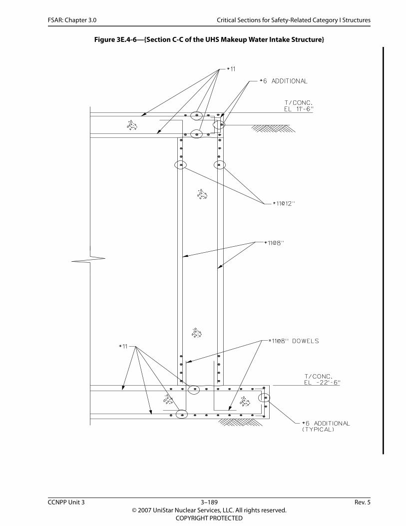
FSAR: Chapter 3.0 Critical Sections for Safety-Related Category I Structures
Figure 3E.4-6—{Section C-C of the UHS Makeup Water Intake Structure}
CCNPP Unit 3 3–189 Rev. 5© 2007 UniStar Nuclear Services, LLC. All rights reserved.
COPYRIGHT PROTECTED

FSAR: Chapter 3.0 Critical Sections for Safety-Related Category I Structures
Figure 3E.4-7—{GT STRUDL Finite Element Planar Reference Frame System}
CCNPP Unit 3 3–190 Rev. 5© 2007 UniStar Nuclear Services, LLC. All rights reserved.
COPYRIGHT PROTECTED

FSAR: Chapter 3.0
Critical Sections for Safety-Related Category I Structures
CCNPP U
nit 33–191
Rev.5©
2007 UniStar N
uclear Services, LLC. All rights reserved.
COPYRIG
HT PRO
TECTED
ls}
Figure 3E.4-8—{Section B-B of the Typical UHS Electrical Building Wal