30– 64 - us pipe · completely remove all welding flux between welding passes. figure 2: welding...
TRANSCRIPT

Water & WasteWaterNSF®
Certified toANSI/NSF 61
2 0 1 3 e d i t i o n
HP LoK® Field Weld30"– 64"

HP LOK® Field WeldNSF®
Certified toANSI/NSF 61
P 2866.
DIP.
PIPE
2 0 1 3 E d i t i o n
REVISED 04.13U.S. PIPE AND FOUNDRY CO. HP LOK FIELD WELD BRO-104
table of ContentsApplication 3
Welding Process 4
General Comments on Pipe Surface Preparation and Welding 5
Field Cutting and Welding Procedure 7
Minimum Laying Lengths for HP LOK® Pipe 19
Procedure for PROTECTO 401™ Epoxy Lined HP LOK® Pipe 20
Products for Water, Wastewater and Fire Protection 21

HP LOK® Field WeldNSF®
Certified toANSI/NSF 61
P 3866.
DIP.
PIPE
2 0 1 3 E d i t i o n
REVISED 04.13U.S. PIPE AND FOUNDRY CO. HP LOK FIELD WELD BRO-104
This brochure describes the procedure to be used in applying a field weld bar to the plain end of field-cut HP LOK® Pipe. The weld bar is an integral component of the HP LOK Joint Restraint system. As such, it is to be applied with careful adherence to this procedure for proper performance. This procedure should only be applied by welders qualified in the skill of Shielded Metal Arc Welding (SMAW).
Note: It may not be necessary to install a Field Weld Bar. Careful planning may permit laying full-length HP LOK pipe into the area that transitions to unrestrained pipe. The overall length may be made up by cutting unrestrained TYTON JOINT® Pipe.
Procedure QualificationThis welding procedure has been qualified in conformance with the American National Standards Institute/American Welding Society Standard ANSI/AWS D11.2-89, Section 8.
application
Figure 1. Employing Field Cuts on Unrestrained Portions of Line

HP LOK® Field WeldNSF®
Certified toANSI/NSF 61
P 4866.
DIP.
PIPE
2 0 1 3 E d i t i o n
REVISED 04.13U.S. PIPE AND FOUNDRY CO. HP LOK FIELD WELD BRO-104
Welding ProcessA properly sized and shaped mild stell ring shall be welded to the plain end of the field-cut HP LOK pipe using the Shield Metal Arc Welding (SMAW) process. Electrodes shall meet the requirements of AWS A5.15 Class ENiFE-CI (See Materials and Equipment section for more information).
Materials and equipment The materials and equipment needed to perform the field welding are as follows:
1. DC Arc Welder The arc welder employed must be capable of using a reverse polarity setup and operate within the electrode manufacturer’s recommended amperage ranges for the electrode size used.
2. AWS 5.15 (Class ENiFe CI) electrodes Electrodes with a diameter of 1/8" or 5/32" for 30" and 36" pipe sizes and 3/16" or smaller electrodes for 42" through 64" pipe sizes. INCO Alloys International, Inc. NI-ROD 55 electrodes meet this specification.
3. A High-Speed Rotary Grinder The grinder is used to remove oxide from the pipe surface and remove laminations that may be present on the outer skin of the pipe. Laminations may be a product of pipe manufacture and will show up as an unattached layer(s) during surface preparation prior to welding.
4. An Oxyacetylene Torch This is an optional method of removing the paint on the surface of the pipe prior to grinding. A torch may not be used to burn off paint, epoxy, or specially lined pipe. Irreversible damage to the lining may occur.
Caution: Some epoxy or specialty pipe linings may burn vigorously if an oxyacetylene torch is used to remove them. If there is any doubt as to the type of lining present, use a grinder to remove the outside coating prior to welding.
5. Field Weld Ring This is a mild steel bar whose proper size is given in Table 1 on page 6 of this document.
6. U.S. Pipe Field Weld Kit This kit contains the necessary fixtures and clamps along with detailed instructions on this procedure. At least two (2) welding fixtures and “C” clamps are required and are present in each kit. For welding epoxy lined pipe, additional clamps are required. Please contact your sales representative or distributor for availability.
7. Epoxy Coating A two (2) component epoxy, such as CARBOLINE BITUMASTIC 300M, Madewell 1104, or INDURON PE54 is used to seal all exposed metal surfaces. This is applied after welding for corrosion protection.
NOTE: Electrode specifications are different for field welding epoxy or specially lined HP LOK Pipe. Refer to the “Procedure for PROTECTO 401 Epoxy Lined HP LOK Pipe” for the modified procedure and Table 4 (on page 20) for the modified welding parameters.
HP LOK® Field WeldNSF®
Certified toANSI/NSF 61
P 5866.
DIP.
PIPE
2 0 1 3 E d i t i o n
REVISED 04.13U.S. PIPE AND FOUNDRY CO. HP LOK FIELD WELD BRO-104
General Comments on Pipe surface Preparation and Welding
The circumferential area of a HP LOK® Pipe, where the field weld bar is to be attached, shall be cleaned to remove contaminants and ground to remove surface oxides to provide a sound, bright, clean area for welding. All surface laminations should also be ground through and eliminated.
The location of the center of the circumferential band ground on the pipe surface shall be at the required distance from the pipe spigot’s end to ensure proper weld bar location; refer to the applicable product drawings or the markings on the fixtures supplied in U.S. Pipe’s HP LOK Field Weld Kit. The width of the ground band shall be at least 0.75" for pipe size 30" – 36" and 800mm – 900mm, and at least 1.25" for pipe size 42" – 64" and 1000mm – 1600mm, to ensure that the weld bar and bead(s) are deposited only on ground pipe surfaces. It is recommended that a welding fixture be used to lay out the area to be ground on the outside diameter of the pipe.
Pipe with thick bark or laminations, which cannot be completely removed without leaving the required minimum pipe wall thickness, shall not be used for HP LOK® Pipe.
The pipe to be welded should preferably be 60º F or warmer. Preheating shall be performed to eliminate any moisture that is present in the weld area. No welding on moist, damp or wet pipe surfaces is permitted.
Table 1 (on page 6) indicates the required size of the finished fillet weld. If the required fillet size is not reached after the number of recommended passes has been made, additional passes should be applied as required to deposit the appropriate amount of filler material.
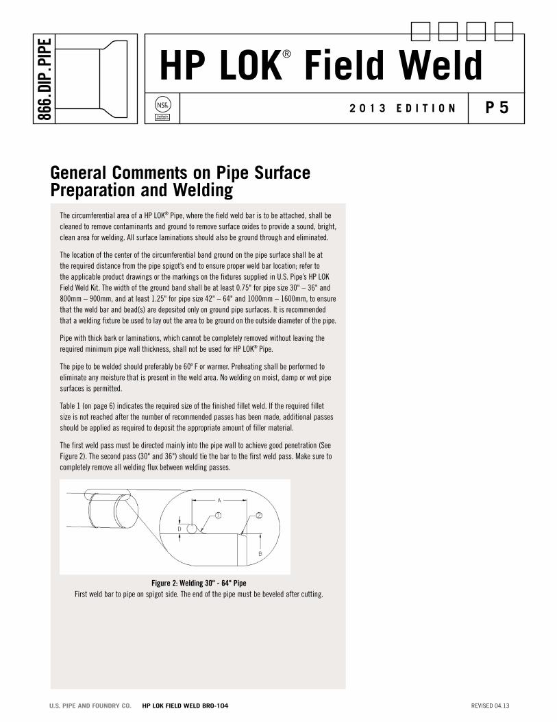
The first weld pass must be directed mainly into the pipe wall to achieve good penetration (See Figure 2). The second pass (30" and 36") should tie the bar to the first weld pass. Make sure to completely remove all welding flux between welding passes.
Figure 2: Welding 30" - 64" Pipe First weld bar to pipe on spigot side. The end of the pipe must be beveled after cutting.

HP LOK® Field WeldNSF®
Certified toANSI/NSF 61
P 6866.
DIP.
PIPE
2 0 1 3 E d i t i o n
REVISED 04.13U.S. PIPE AND FOUNDRY CO. HP LOK FIELD WELD BRO-104
Figure 3: Welding 30" - 64" Pipe
For 30" – 64" sizes, weld to be made in four passes as follows:
1. Weld bar to pipe with first pass. 2. Weld to first pass and pipe extending weld length to a minimum of 3/4". 3. Weld bar to existing welds to a nominal height of 5/16". The weld shall not exceed bar height. 4. Weld single pass on back side of bar. This weld should not protrude past edge of bar.
General Comments on Pipe surface Preparation and Welding (cont.)
For 30" – 64" sizes, four (4) weld passes are required as shown in Figure 3. Direct the first and sec-ond weld passes mainly into the pipe wall to accomplish good penetration and proper fillet length of 3/4". The third pass should weld the bar to the first two (2) passes. The fourth pass is placed on the opposite side of the bar. This pass must be ground to keep the weld under the edge of the bar.
a B* C
siZeInches
Bar FroM Cut end distanCe
Inches
MaxiMuM PiPe o.d.
Inches
MiniMuM PiPe o.d.
Inches
Bar diaMeter
Inches
Bari.d.
Inches
MiniMuM no. oF WeLd
Passes
aPProx. no. oF
WeLdinGrods
reQuired
FiLLet siZe
Inches
30 6-1/8 32.08 31.94 5/16 32.00 3/1 40 3/4L x 5/16H
36 6-1/8 38.38 38.24 5/16 38.30 3/1 45 3/4L x 5/16H
42 6-5/8 44.58 44.44 5/16 44.50 3/1 50 3/4L x 5/16H
48 6-5/8 50.88 50.74 5/16 50.80 3/1 65 3/4L x 5/16H
54 6-5/8 57.60 57.46 5/16 57.56 3/1 75 3/4L x 5/16H
60 6-5/8 61.65 61.51 5/16 61.61 3/1 85 3/4L x 5/16H
64 6-5/8 65.71 65.57 5/16 65.67 3/1 90 3/4L x 5/16H
Table 1: Bar Size, Location and Dimensional Specifications
*NOTE: For accuracy, a diameter tape graduated in 100th’s must be used.

HP LOK® Field WeldNSF®
Certified toANSI/NSF 61
P 7866.
DIP.
PIPE
2 0 1 3 E d i t i o n
REVISED 04.13U.S. PIPE AND FOUNDRY CO. HP LOK FIELD WELD BRO-104
Step 1: Measure the Pipe Diameter To determine if the pipe is suitable for cutting, measure the pipe diameter or circumference; (diameter = circumference divided by 3.142) at the location to be cut. Take this measurement square with the longitudinal axis of the pipe. If the dimensions are outside the range given in Table 1, select another pipe and repeat this procedure.
Step 2: Mark the Location of the Cut Pipe End Where installations require precise lay lengths, the joint pullout included in Table 2 must be taken into consideration. In HP LOK® Pipe and Fitting sockets, there is a small amount of slack or pullout available at each joint. This pullout or expansion capability, is the result of clearance inside the socket required for the insertion of the locking ring during the joint assembly. The expansion can be minimized by extending the joint after installing the locking ring and prior to setting the joint deflec-tion. Please note that if the joint is not extended during assembly, the expansion per joint during line pressurization will increase the length of a 1000-foot long installation by from 2' to 5', depending upon the pipe size.
A line must be scribed or otherwise marked on the circumference of the pipe at the proposed cut location to ensure that the cut will be square. Any marking material can be used. Chalk is shown here and is a good choice for marking on areas to be welded as it will not contaminate the weld.
Field Cutting and Welding Procedure
Table 2: Joint Pull Out
SIZEInches
PULL OUTInches
30 .55
36 .55
42 .55
48 .55
54 .55
60 .55
64 .55
HP LOK® Field WeldNSF®
Certified toANSI/NSF 61
P 8866.
DIP.
PIPE
2 0 1 3 E d i t i o n
REVISED 04.13U.S. PIPE AND FOUNDRY CO. HP LOK FIELD WELD BRO-104
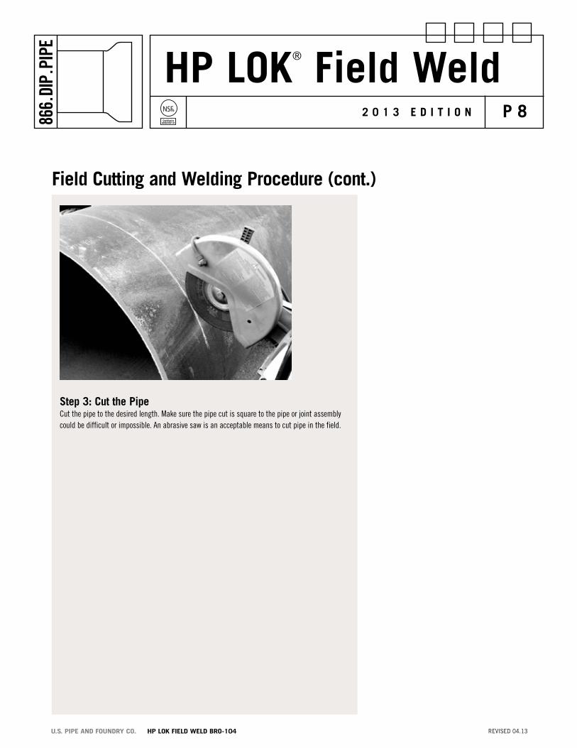
step 3: Cut the Pipe Cut the pipe to the desired length. Make sure the pipe cut is square to the pipe or joint assembly could be difficult or impossible. An abrasive saw is an acceptable means to cut pipe in the field.
Field Cutting and Welding Procedure (cont.)

HP LOK® Field WeldNSF®
Certified toANSI/NSF 61
P 9866.
DIP.
PIPE
2 0 1 3 E d i t i o n
REVISED 04.13U.S. PIPE AND FOUNDRY CO. HP LOK FIELD WELD BRO-104
step 4: Bevel the Cut end Bevel the cut end using a grinder. The outside of the field cut end (or any other pipe without a bevel) should match the bevel on a factory beveled pipe. Round the leading edge of the spigot end and remove any sharp, rough edges which might cut or snag the gasket. Additional grinding may be required to further bevel the pipe if difficulty in assembly is noted.
step 5: adjust the Collet Position Set the collet on the welding fixtures to the correct pipe size. The face of the collet closest to the V notch of the fixture (bar) should be aligned with the mark in the fixture.
Field Cutting and Welding Procedure (cont.)

HP LOK® Field WeldNSF®
Certified toANSI/NSF 61
P 10866.
DIP.
PIPE
2 0 1 3 E d i t i o n
REVISED 04.13U.S. PIPE AND FOUNDRY CO. HP LOK FIELD WELD BRO-104
step 6: Mark the Location of the Field Weld Bar Mark the bar location from the cut end using the welding fixture as a guide. Again chalk may be used for this operation. Since this is an area that will be welded, avoid using marking instruments that contain lead, grease or other contaminants. Mark the complete circumference of the pipe making sure the mark is straight around the pipe.
Field Cutting and Welding Procedure (cont.)

HP LOK® Field WeldNSF®
Certified toANSI/NSF 61
P 11866.
DIP.
PIPE
2 0 1 3 E d i t i o n
REVISED 04.13U.S. PIPE AND FOUNDRY CO. HP LOK FIELD WELD BRO-104
step 7: surface Preparation Burn the paint from the pipe at the bar location with a torch; then grind the pipe surface over a width of about 2 inches. It is very important that the pipe surface be clean and freshly ground all the way through the pipe dimples anywhere weld will contact the pipe.
Mark the bar location again as in step 6. The mark should be in the ground area of the pipe. Again, take care to use chalk or other marking device that does not contain lead, grease or other contaminants.
The circumferential area of the pipe where the field weld bar is to be attached, shall be cleaned to remove contaminates and ground to remove surface oxides to provide a sound, bright, clean area for welding. All surface laminations should be ground through and eliminated.
Field Cutting and Welding Procedure (cont.)
HP LOK® Field WeldNSF®
Certified toANSI/NSF 61
P 12866.
DIP.
PIPE
2 0 1 3 E d i t i o n
REVISED 04.13U.S. PIPE AND FOUNDRY CO. HP LOK FIELD WELD BRO-104
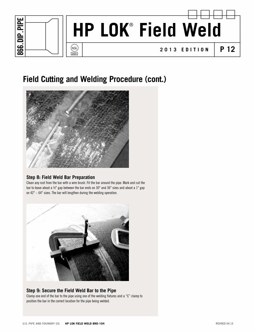
step 8: Field Weld Bar Preparation Clean any rust from the bar with a wire brush. Fit the bar around the pipe. Mark and cut the bar to leave about a ½" gap between the bar ends on 30" and 36" sizes and about a 1" gap on 42" – 64" sizes. The bar will lengthen during the welding operation.
Field Cutting and Welding Procedure (cont.)
step 9: secure the Field Weld Bar to the Pipe Clamp one end of the bar to the pipe using one of the welding fixtures and a “C” clamp toposition the bar in the correct location for the pipe being welded.

HP LOK® Field WeldNSF®
Certified toANSI/NSF 61
P 13866.
DIP.
PIPE
2 0 1 3 E d i t i o n
REVISED 04.13U.S. PIPE AND FOUNDRY CO. HP LOK FIELD WELD BRO-104
step 10: secure the Field Weld Bar for Welding Clamp a second fixture 6" – 8" inches from the first fixture. If in doubt, clamp the second fix-ture to the bar closer than you believe necessary. If too much length is left between clamping fixtures, the bar will move out of position during welding due to the thermal expansion of the bar as it is heated. Tap the bar down with a hammer, if necessary, to fit the bar to the pipe surface. The bar must remain in close contact with the pipe or the integrity of the joint cannot be ensured. Assembly may also be difficult or impossible if the bar changes position in relation to the pipe surface or cut end during welding.
Field Cutting and Welding Procedure (cont.)

HP LOK® Field WeldNSF®
Certified toANSI/NSF 61
P 14866.
DIP.
PIPE
2 0 1 3 E d i t i o n
REVISED 04.13U.S. PIPE AND FOUNDRY CO. HP LOK FIELD WELD BRO-104
step 11: Make the initial Weld Weld the first pass on the portion of the bar between the two (2) welding fixtures. Weld on the side of the bar next to the cut end of the pipe. Although all passes may be welded as you go, it is preferable to complete the first pass then return and weld the second and third passes.
Field Cutting and Welding Procedure (cont.)

HP LOK® Field WeldNSF®
Certified toANSI/NSF 61
P 15866.
DIP.
PIPE
2 0 1 3 E d i t i o n
REVISED 04.13U.S. PIPE AND FOUNDRY CO. HP LOK FIELD WELD BRO-104
step 12: Continue to Weld around the Pipe Circumference After making the weld passes between the two (2) “C” clamp fixtures, unclamp the first fixture and reattach it approximately six to eight inches farther around the pipe and bar. The other clamp fixture can now be removed and welding continued with only one (1) clamp fixture since the trailing weld will hold the bar onto the pipe. After welding in the described method, the ends of the bar should be welded to the pipe with a gap of approximately 1". The bar ends cannot be welded together nor can they be allowed to touch during the welding procedure. If this occurs, it is very likely that the growth of the weld ring due to the heat of welding will raise the bar off of the pipe surface. This will create a weak assembly and may interfere with later joint assembly.
Field Cutting and Welding Procedure (cont.)

HP LOK® Field WeldNSF®
Certified toANSI/NSF 61
P 16866.
DIP.
PIPE
2 0 1 3 E d i t i o n
REVISED 04.13U.S. PIPE AND FOUNDRY CO. HP LOK FIELD WELD BRO-104
step 13: Completed Front side Bead The completed front side (side closest to the spigot end of the pipe) weld bead should be similar in appearance to the picture above. See Table 1 and Figure 3 on page 6 for Weld Dimensions.
Field Cutting and Welding Procedure (cont.)

HP LOK® Field WeldNSF®
Certified toANSI/NSF 61
P 17866.
DIP.
PIPE
2 0 1 3 E d i t i o n
REVISED 04.13U.S. PIPE AND FOUNDRY CO. HP LOK FIELD WELD BRO-104
step 14: add the Backside Weld and Grind Flush with Bar edge
See Figure 3 for the location of the fourth weld. This weld is placed on the opposite side of the field bar and should be ground so that no weld extends beyond the edge of the field bar. The finished product should have a flat vertical (from the pipe) surface between the bar and the pipe. It is important that this weld be finished so as not to form a ramp that would allow the HP LOK® Locking Ring to ride over the bar.
Field Cutting and Welding Procedure (cont.)

HP LOK® Field WeldNSF®
Certified toANSI/NSF 61
P 18866.
DIP.
PIPE
2 0 1 3 E d i t i o n
REVISED 04.13U.S. PIPE AND FOUNDRY CO. HP LOK FIELD WELD BRO-104
step 15: apply the Protective Coating After the welding is completed, remove all of the weld flux and spatter from the bar and pipe by grinding or other suitable means. The weld bar, weld fillet/s and any ground surfac-es shall be coated with a two-part epoxy for corrosive soil environments or asphaltic paint for other environments. The only exception to this is if the application of a coating on the bar and weld area are incompatible with any additional top coat required by the custom-ers purchase specification. In that case, a compatible corrosion inhibiting coating may be applied. This epoxy coating shall not extend into the gasket sealing area of the spigot.
step 16: Product Lining/Coating repairs The linings of all cement-lined pipe that are welded shall be checked for cracks and looseness. Any poorly bonded lining shall be removed, and the exposed pipe surfaces shall be patched in accordance with the requirements of ANSI/AWWA C104/A21.4, Cement-Mortar Lining for Ductile-Iron Pipe and Fittings for Water. Repaired cement linings shall be coated with an approved asphaltic paint that is approved for potable water. Any damage to special linings shall be repaired in accordance with the lining material manufacturer’s recommendations.
Field Cutting and Welding Procedure (cont.)
HP LOK® Field WeldNSF®
Certified toANSI/NSF 61
P 19866.
DIP.
PIPE
2 0 1 3 E d i t i o n
REVISED 04.13U.S. PIPE AND FOUNDRY CO. HP LOK FIELD WELD BRO-104
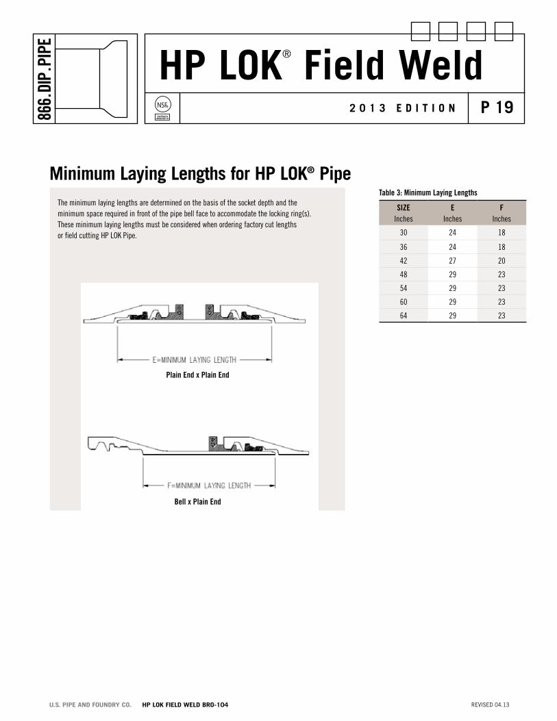
The minimum laying lengths are determined on the basis of the socket depth and the minimum space required in front of the pipe bell face to accommodate the locking ring(s). These minimum laying lengths must be considered when ordering factory cut lengths or field cutting HP LOK Pipe.
Table 3: Minimum Laying Lengths
Minimum Laying Lengths for HP LoK® Pipe
Plain End x Plain End
Bell x Plain End
SIZEInches
EInches
FInches
30 24 18
36 24 18
42 27 20
48 29 23
54 29 23
60 29 23
64 29 23

HP LOK® Field WeldNSF®
Certified toANSI/NSF 61
P 20866.
DIP.
PIPE
2 0 1 3 E d i t i o n
REVISED 04.13U.S. PIPE AND FOUNDRY CO. HP LOK FIELD WELD BRO-104
Procedure for ProteCto 401™ epoxy Lined HP LoK® PipeThe following describes the recommended procedure and materials to be used for the field welding of a steel bar to an epoxy or Polymeric Lined HP LOK Pipe that has been cut in the field:
1. AWS 5.15 (Class ENiFe Cl) electrodes Use electrodes with a diameter of 1/8” or 5/32” for 30” and 36” pipe sizes and 3/16” or smaller electrodes for 42” through 64” pipe sizes. INCO Alloys International, Inc. NI-ROD 55 electrodes meet this specification.
2. For field cutting and welding procedure, refer to Steps 1 – 16 (pages 7 through 18) in this brochure.
3. Field cuts, holidays, and any damaged areas from the welding process to the protective lining must be repaired. Follow the manufacturer’s repair and touch-up procedures that accompany the PROTECTO 401™ repair kits for the damaged lining areas.

HP LOK® Field WeldNSF®
Certified toANSI/NSF 61
P 21866.
DIP.
PIPE
2 0 1 3 E d i t i o n
REVISED 04.13U.S. PIPE AND FOUNDRY CO. HP LOK FIELD WELD BRO-104
Products for Water, Wastewater and Fire Protectionductile iron Pipe siZe ranGe
TYTON JOINT® Pipe 3"-64" Ductile Iron
Mechanical Joint Pipe 4"-12" Ductile Iron
TR FLEX® Pipe 4"-36" Ductile Iron
HP LOK® Pipe 30"-64" Ductile Iron
Flanged Pipe 3"-64" Ductile Iron
Grooved Pipe 4”-36” Ductile Iron
USIFLEX® Boltless Ball Joint Pipe 4"-48" Ductile Iron For Subaqueous Installations
restrained Joints
TR FLEX® Restrained Joint 4"-36" Ductile Iron
HP LOK® Restrained Joint 30"-64" Ductile Iron
MJ FIELD LOK® Gaskets 4"-24"
FIELD LOK 350® Gaskets 4"-24"
FIELD LOK® Gasket 30" & 36"
TR FLEX GRIPPER® Rings 4"-36" Ductile Iron
TR TELE FLEX® Assemblies 4"-24" Ductile Iron
Fittings
TYTON® Fittings 14"-24" Ductile Iron
TRIM TYTON® Fittings 4”-12” Ductile Iron
TR FLEX® Fittings and TR FLEX® Telescoping Sleeves 4"-36" Ductile Iron
HP LOK® Fittings and HP LOK® Telescoping Sleeves 30”-64” Ductile Iron
Mechanical Joint Fittings 30"-48" Ductile Iron
Flanged Fittings 30"-64" Ductile Iron
XTRA FLEX® Couplings 4"-24" Ductile Iron
Miscellaneous Products
PROTECTO 401™ Lined Ductile Iron Pipe for 4"-64" Ductile Iron Domestic Sewage and Industrial Wastes
GLASS Lined Ductile Iron Pipe for Wastewater 4”-30” Ductile Iron Treatment Plants
RING FLANGE-TYTE® Gaskets 4"-36"
FULL FACE FLANGE-TYTE® Gaskets 4"-64"
MJ Harness-Lok 4”-48” Ductile Iron
Saddle Outlets Various Ductile Iron
Welded Outlets Various Ductile Iron
Polyethylene Encasement 4"-64"
Our products are manufactured in conformance with National Standards so that our customers may be assured of getting the performance and longevity they expect. Use of accessories or other appurtenances that do not comply with recognized standards may jeopardize the performance and longevity of the project.

P.o. Box 10406Birmingham, aL 35202
866.diP.PiPe (866.347.7473)Fax 205.254.7165
www.uspipe.com
All U.S. Pipe brochures and/or products are subject to change without further notice.
reGionaL saLes oFFiCes
eastern reGionaL oFFiCe(609) 387-6120 (Phone)
(609) 387-6050 (Fax)
Western reGionaL oFFiCe(815) 725-7168 (Phone)
(815) 725-7165 (Fax)
PaCiFiC Coast reGionaL oFFiCe(510) 441-5800 (Phone)
(510) 441-5885 (Fax)
soutHern reGionaL oFFiCe(205) 254-7229 (Phone)
(205) 254-7009 (Fax)
internationaL saLes oFFiCe(205) 254-7230 (Phone)
(205) 254-7274 (Fax)