3. the orbit in space - ltas-sdrg :: welcome ! · 2016-09-17 · the earth's core and mantle,...
TRANSCRIPT

Gaëtan Kerschen
Space Structures &
Systems Lab (S3L)
3. The Orbit in Space
Astrodynamics (AERO0024)

2
Motivation: Space
We need means of describing orbits in three-dimensional
space.
YES !
NO !
Example: Earth’s oblateness
Atmosphere

3
3-D Space: Example
Two-body propagator J2 propagator

4
3-D Space: Example
Two-body propagator Two-body + drag

5
Complexity of Coordinate Systems: STK

6
3. The Orbit in Space and Time
3.1 Inertial frames
3.2 Coordinate systems
3.3 Coordinate types
ω δ
θ α
Ω a
e
i
?

7
3. The Orbit in Space and Time
3.1 Inertial frames
3.1.1 ICRS
3.1.2 ICRF
ω δ
θ α
Ω a
e
i
?

8
Importance of Inertial Frames
An inertial reference frame is defined as a system that is
neither rotating nor accelerating relative to a certain
reference point.
Suitable inertial frames are required for orbit description
(remember that Newton’s second law is to be expressed in
an inertial frame).
An inertial frame is also an appropriate coordinate system
for expressing positions and motions of celestial objects.
3.1.1 ICRS

9
Distinction between reference system and a reference
frame:
1. A reference system is the complete specification of how a
celestial coordinate system is to be formed. For instance, it
defines the origin and fundamental planes (or axes) of the
coordinate system.
2. A reference frame consists of a set of identifiable points
on the sky along with their coordinates, which serves as the
practical realization of a reference system.
Reference System and Reference Frame
3.1.1 ICRS

10
International Celestial Reference System (ICRS)
The ICRS is the reference system of the International
Astronomical Union (IAU) for high-precision astronomy.
Its origin is located at the barycenter of the solar system.
Definition of non-rotating axes:
1. The celestial pole is the Earth’s north pole (or the fundamental
plane is the Earth's equatorial plane).
2. The reference direction is the vernal equinox (point at which the
Sun crosses the equatorial plane moving from south to north).
3. Right-handed system.
3.1.1 ICRS

11
Vernal Equinox ?
The vernal equinox is the intersection of the ecliptic and equator
planes, where the sun passes from the southern to the northern
hemisphere (First day of spring in the northern hemisphere).
Today, the vernal equinox points in the direction of the
constellation Pisces, whereas it pointed in the direction of the
constellation Ram during Christ’s lifetime. Why ?
Vallado, Kluwer, 2001.

12 3.1.1 ICRS
Rotation Axis: Lunisolar Precession
Because of the gravitational tidal forces of the Moon and
Sun, the Earth’s spin axis precesses westward around the
normal to the ecliptic at a rate of 1.4/century. The Earth's
axis sweeps out a cone of 23.3 degrees in 26000 years.
f1
f2
F
F: dominant force on
the spherical mass.
f1, f2: forces due to the
bulging sides; f1 > f2,
which implies a net
clockwise moment.
ωE
ecliptic

13 3.1.1 ICRS
Rotation Axis: Lunisolar Precession
T=26000 years
Competition between two
effects:
1. Gyroscopic stiffness
of the spinning Earth
(maintain orientation
in inertial space).
2. Gravity gradient torque
(pull the equatorial
bulge into the plane of
the ecliptic).

14 3.1.1 ICRS
Rotation Axis: Nutation
The obliquity of the Earth varies with a maximum
amplitude of 0.00025 over a period of 18.6 years.
This nutation is caused by the precession of the Moon’s
orbital nodes. They complete a revolution in 18.6 years.

15 3.1.1 ICRS
Yet Another Disturbance: Polar Motion
Movement of Earth’s rotation axis across its surface.
Difference between the instantaneous rotational axis and
the conventional international origin (CIO a
conventionally defined reference axis of the pole's average
location over the year 1900).
The drift, about 20 m since 1900, is partly due to motions in
the Earth's core and mantle, and partly to the redistribution
of water mass as the Greenland ice sheet melts.

16 3.1.1 ICRS
Yet Another Disturbance: Polar Motion
CIO: fixed with
respect to the
surface of the
Earth
CEP: periodic
motion (celestial
ephemeris pole)

17
Complicated Motion of the Earth
3.1.1 ICRS
18
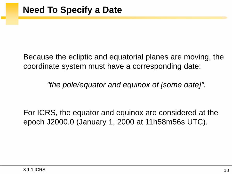
Need To Specify a Date
Because the ecliptic and equatorial planes are moving, the
coordinate system must have a corresponding date:
"the pole/equator and equinox of [some date]".
For ICRS, the equator and equinox are considered at the
epoch J2000.0 (January 1, 2000 at 11h58m56s UTC).
3.1.1 ICRS

19
ICRS in Summary
Quasi-equatorial coordinates at the solar system barycenter !
[…in the framework of general relativity…]
3.1.1 ICRS
An object is located in the ICRS using
right ascension and declination
But how to realize ICRS
practically ?

20
Previous Realizations: B1950 and J2000
B1950 and J2000 were considered the best realized inertial
axes until the development of ICRF.
They exploit star catalogs (FK4 and FK5, respectively) which
provide mean positions and proper motions for classical
fundamental stars (optical measurements):
FK4 was published in 1963 and contained
1535 stars in various equinoxes from 1950
to 1975.
FK5 was an update of FK4 in 1988 with
new positions for the 1535 stars. STK
3.1.2 ICRF

Fifth Fundamental
Catalog (FK5), available
on the web site

22
Star Catalogs: Limitations and Improvement
1. The uncertainties in the star positions of the FK5 are
about 30-40 milliarcseconds over most of the sky.
2. A stellar reference frame is time-dependent because
stars exhibit detectable motions.
1. Uncertainties of radio source positions are now
typically less than one milliarcsecond, and often a
factor of ten better.
2. Radio sources are not expected to show measurable
intrinsic motion.
3.1.2 ICRF

Fifth Fundamental
Catalog (FK5), available
on the web site

24
ICRF is the Current Realization of ICRS
Since 1998, IAU adopted the International Celestial
Reference Frame (ICRF) as the standard reference frame:
quasi-inertial reference frame with barely no time
dependency.
It represents an improvement upon the theory behind the
J2000 frame, and it is the best realization of an inertial
frame constructed to date.
3.1.2 ICRF

25
Very Long Baseline Interferometry
STK
3.1.2 ICRF

26
Further Reading on the Web Site
3.1.2 ICRF
28
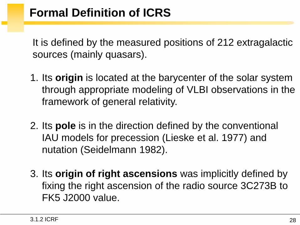
Formal Definition of ICRS
1. Its origin is located at the barycenter of the solar system
through appropriate modeling of VLBI observations in the
framework of general relativity.
2. Its pole is in the direction defined by the conventional
IAU models for precession (Lieske et al. 1977) and
nutation (Seidelmann 1982).
3. Its origin of right ascensions was implicitly defined by
fixing the right ascension of the radio source 3C273B to
FK5 J2000 value.
3.1.2 ICRF
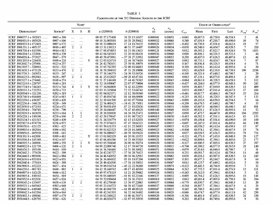
It is defined by the measured positions of 212 extragalactic
sources (mainly quasars).

29
3. The Orbit in Space and Time
3.2 Coordinate systems
ω δ
θ α
Ω a
e
i
?

30
Coordinate Systems
3.2 Coordinate systems
Now that we have defined an inertial reference frame, other
reference frames can be defined according to the needs of
the considered application.
Coordinate transformations between two reference frames
involve rotation and translation.
What are the possibilities for a satellite in Earth orbit ?

31
Geocentric — Inertial (ECI)
A geocentric-equatorial system is clearly convenient.
The geocentric celestial reference frame (GCRF) is the
geocentric counterpart of the ICRF and is the standard
inertial coordinate system for the Earth.
3.2 Coordinate systems

32
Geocentric — Fixed (ECEF)
Origin at the Earth’s center.
z-axis is parallel to Earth’s rotation vector.
x-axis passes through the Greenwich meridian.
y-axis: right-handed set.
For ground tracks and force computation.
3.2 Coordinate systems

33
ECEF
3.2 Coordinate systems

34
ECEF-ECI Transformation
It includes precession, nutation, and rotation effects, as well
as pole wander and frame corrections.
ECEF
ECI
PM
N
P
ST
3.2 Coordinate systems
e.g., ITRF
e.g., FK5

35
ECEF-ECI Transformation
Vallado, Fundamental of Astrodynamics and Applications, Kluwer, 2001.

36
Simplified transformation
Precession, nutation, polar motion ignored
3.2 Coordinate systems
ECEF-ECI Transformation


38
Topocentric — On the Earth’s Surface
For satellite tracking
SEZ or NEZ
3.2 Coordinate systems

39
Satellite coordinate system
Perifocal coordinate system
Heliocentric coordinate system
Non-singular elements
Yet More Coordinate Systems !
For interplanetary
missions
For particular orbits
Natural frame for an
orbit (z is zero)
For ADCS
3.2 Coordinate systems

40
3. The Orbit in Space and Time
3.3 Coordinate types
ω δ
θ α
Ω a
e
i
?

41
Cartesian and Spherical
1. Cartesian: for computations
2. Spherical: azimuth and elevation (for ground station) —right ascension and declination (for astronomers)
I
K
J
3.3 Coordinate types

42
Cartesian ↔ Spherical
ˆ ˆ ˆ ˆrX Y Z r r I J K u
ˆ ˆ ˆˆ cos cos cos sin sinr u I J K
3.3 Coordinate types

43
Orbitron
http://www.stoff.pl/

44
Orbitron: Close-Up
3.3 Coordinate types

45
Orbital (Keplerian) Elements
For interpretation
r and v do not directly yield much information about the
orbit. We cannot even infer from them what type of conic
the orbit represents !
Another set of six variables, which is much more
descriptive of the orbit, is needed.
3.3 Coordinate types

46
1. e: shape of the orbit
2. a: size of the orbit
3. i: orients the orbital plane with
respect to the ecliptic plane
4. Ω: longitude of the intersection
of the orbital and ecliptic planes
5. ω: orients the semi-major axis
with respect to the ascending
node
6. ν: orients the celestial body in
space
6 Orbital (Keplerian) Elements
definition of the orbital plane
definition of the ellipse
orientation of the ellipse within
the orbital plane
position of the satellite on the
ellipse
3.3 Coordinate types

Orbital plane orientation of
the ellipse
position of
the satellite
Ecliptic plane


49
Orbital Elements From State Vector
,r v
, ,
, ,
a i e
3.3 Coordinate types

50
Orbital Elements From State Vector
I
K
J
3.3 Coordinate types

51
Hints
Order: e,a / i,Ω,,ω,θ
e,a: L2
i: where is h ?
Ω: use the line of nodes
ω: use e
θ: use ω
3.3 Coordinate types

52
Eccentricity (First Integral of Motion)
/er
r
v r v
r r
r r
e v h v r v
3.3 Coordinate types

53
Semi-Major Axis (Vis-Viva Equation)
2 1ellipv
r a
2
2
ra
rv
,r v r v
3.3 Coordinate types

54
Inclination (Geometrical Arguments)
1 1ˆ( ).
cos coszhi
h
r v K
r v
h r v ˆ.zh h K
Normal to the
orbit plane Normal to the
equatorial plane
3.3 Coordinate types

55
Longitude Ω (Geometrical Arguments)
ˆh
h
n K
Nodal vector Where is n ?
1 1
ˆ ˆ.ˆ.
cos cos
ˆn
r vK I
r vn I
r vK
r v
In the orbital and equatorial
planes, and, hence, along
the line of nodes
If ˆ. 0n J

56
Argument of Perigee (Geom. Arguments)
r
v r v re
1 1
ˆ ..
cos cos
ˆ
r
ne
r
v r vr v rK
r vn e
v r vr v rK
r v
Its direction corresponds
to the apse line
If ˆ. 0e K

57
True Anomaly (Geometrical Arguments)
1 1
..
cos cosr
rer
r
v r v rr
r e
v r v r
If . 0r v
3.3 Coordinate types

58
Remarks
1ˆ.
2 cosn
n IIf ˆ. 0n J
If ˆ. 0e K1 .
2 cosne
n e
If . 0r v1 .
2 cosre
r e
3.3 Coordinate types

State Vector From Orbital Elements
59 3.3 Coordinate types
See exercice session.

60
Matlab Example
3.3 Coordinate types

61
Two-Line Elements (TLE)
For monitoring
by Norad *
* North American Aerospace Defense Command

62
Celestrak: Update TLE
http://www.celestrak.com/NORAD/elements/
63
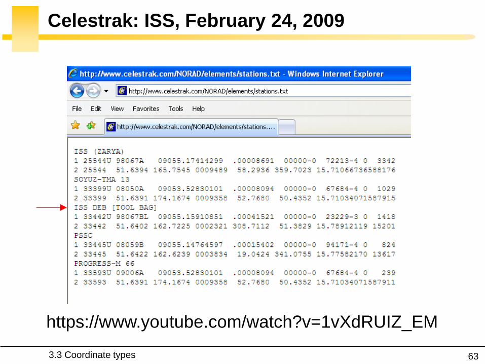
Celestrak: ISS, February 24, 2009
3.3 Coordinate types
https://www.youtube.com/watch?v=1vXdRUIZ_EM

64
Lost ISS Toolbag: Guess What ?
3.3 Coordinate types

65
Celestrak: IRIDIUM 33, February 24, 2009

66
3. The Orbit in Space and Time
3.1 INERTIAL FRAMES
3.1.1 ICRS
3.1.2 ICRF
3.2 COORDINATE SYSTEMS
3.3 COORDINATE TYPES

67
Gaëtan Kerschen
Space Structures &
Systems Lab (S3L)
3. The Orbit in Space
Astrodynamics (AERO0024)