3-point boom sprayers - gearmoreintroduction page 1 we welcome you as an owner of the gearmore...
TRANSCRIPT

3-POINT BOOMSPRAYERS
Assembly, Operation &Parts Manual For
Model GN100D-23,GN150D-23 & GN200D-23
February 2004
FORM: GN100D-23Bk.QXD

Introduction . . . . . . . . . . . . . . . . . . . . . . . . . . . . . . . . . . . . . . . . . . . . . . . . . . .1
Sprayer Operation . . . . . . . . . . . . . . . . . . . . . . . . . . . . . . . . . . . . . . . . . . . . . .2
Lubrication . . . . . . . . . . . . . . . . . . . . . . . . . . . . . . . . . . . . . . . . . . . . . . . . . . . .3
General Maintenance . . . . . . . . . . . . . . . . . . . . . . . . . . . . . . . . . . . . . . . . . . . .4
Cleaning & Storage . . . . . . . . . . . . . . . . . . . . . . . . . . . . . . . . . . . . . . . . . . . . .4
General Safety Information & Tips . . . . . . . . . . . . . . . . . . . . . . . . . . . . . .5-6
Pump Maintenance . . . . . . . . . . . . . . . . . . . . . . . . . . . . . . . . . . . . . . . . . . . . .7
Pump Diaphragm & Valve Replacement . . . . . . . . . . . . . . . . . . . . . . . . . . . .8
Troubleshooting . . . . . . . . . . . . . . . . . . . . . . . . . . . . . . . . . . . . . . . . . . . . . . . .9
Tank & Frame Assembly . . . . . . . . . . . . . . . . . . . . . . . . . . . . . . . . . . . . .10-12
Agitator Assembly . . . . . . . . . . . . . . . . . . . . . . . . . . . . . . . . . . . . . . . . . .13-14
Sprayer Boom . . . . . . . . . . . . . . . . . . . . . . . . . . . . . . . . . . . . . . . . . . . . . .15-17
Nozzle Spacing . . . . . . . . . . . . . . . . . . . . . . . . . . . . . . . . . . . . . . . . . . . . . . .18
Tommy Gun Assembly . . . . . . . . . . . . . . . . . . . . . . . . . . . . . . . . . . . . . .19-20
Run of Fluids . . . . . . . . . . . . . . . . . . . . . . . . . . . . . . . . . . . . . . . . . . . . . .21-22
AR1064 Pump Assembly . . . . . . . . . . . . . . . . . . . . . . . . . . . . . . . . . . . . .23-25
VDR50S Valve Assembly . . . . . . . . . . . . . . . . . . . . . . . . . . . . . . . . . . . . .26-27
Driveline Parts List . . . . . . . . . . . . . . . . . . . . . . . . . . . . . . . . . . . . . . . . . . . .28
Limited Warranty . . . . . . . . . . . . . . . . . . . . . . . . . . . . . . . . . . . . . . . . . . . . . .29
TABLE OF CONTENTS
Date of Purchase:__________________________
Model Number:____________________________
Serial Number:____________________________
INTRODUCTION
Page 1
We welcome you as an owner of the Gearmore 3-Point Hitch, Handgun-Boom Sprayer.
Before you read on to the operation and maintenance of the sprayer, please read the following generalinformation.
POWER SOURCE - The sprayer is designed to mount to any 540 R.P.M. tractor with a 3-pointhitch.
PUMP - The pump on the sprayer is a diaphragm pump. Pistons power the diaphragms that pumpthe liquid. The unit has protection against corrosion, as the valves are stainless steel and other partsthat come in contact with the liquid are plastic coated or brass.
TANK - The tank comes with a mechanical agitation system. It also has a sump so the tank can becompletely drained.
STRAINERS - The sprayer is equipped with two strainers. A large filter screen is located under thetank cover and the main strainer located under the tank. When cleaning main strainer screen, makesure to turn shut-off valve handle 90 degrees from parallel position, which is off.
BEFORE OPERATING YOUR NEW SPRAYER
1. Inspect for damage and loose or missing parts. Make sure all fittings and drive components are secure.
2. Lubricate. (See lubrication section for details)
3. Check tank for any foreign objects.
4. Fill tank 1/2 full with clean water. DO NOT add spray chemicals until sprayer is started, adjusted and calibrated.

SPRAYER OPERATION
Page 2
1. Connect sprayer to tractor 3-point hitch.
2. Connect up P.,T.O. driveshaft, after you have checked to make sure the driveshaft is not too long.
3. Check strainer screen to make sure it is clean.
4. Check strainer shut-off valve, making sure the handle is parallel to piping - the open position.
5. Engage tractor P.T.O. and run for a couple of minutes to make sure your chemical is mixed.
6. Set regulator pressure as required.IMPORTANT: The pressure regulator valve should be open (no pressure) before operating sprayer. Then gradually adjust to desired pressure. Failure to operate in this manner could cause a sudden surge, which could damage the sprayer pump.
7. If using a handgun to spray, just connect the hose to the hose fitting valve and turn on when using.
8. If you purchased the optional sprayer boom, connect the 3 hoses from the boom to the 3 on-off valves. Turn hand valves on or off depending on your requirements forleft, right or full boom spraying.
The boom nozzle spray tips are a general purpose flat fan type. If other sizes or types are required, use "Spray Systems" or equal.

LUBRICATION
Page 3
DRIVESHAFT - The driveshaft comes not greased, so it must be done before sprayers is putto use. After that, grease every 8 hours. It is also necessary, from time to time, to untelescopethe driveshaft to clean and re-grease tubings.
PUMP - The clear oil reservoir should be filled to the indicator mark. If oil is low, add SAE 30weight engine oil, non-foaming. The pump is equipped with a pressure accumulator to preventvibration.
WARNING: The air pressure in the pulsation damper should never exceedthe working pressure of the pump. The air pressure in the damper should be10% of working pressure. Minimum charge should be 10 PSI.
MECHANICAL AGITATOR - The large brass hex nut on the end of agitator shaft has pack-ing inside to prevent leaks. In addition, a grease zerk is provided and should be greased every 8hours. If leaking occurs after greasing, the packing amy have to be tightened by turning the brassnut. (Be careful to NOT overtighten the nut) If leaking stall occurs, the packing may have to bereplaced.

Page 4
GENERAL MAINTENANCE
Carefully follow all instructions as stated in this operator's manual. This includes lubrication,maintenance and operation of the sprayer. The sprayer was designed and built for years ofreliable service, if properly cared for. However, a sprayer is a precision machine, thus dailyattention is required.
Check bolts for tightness.
Check sprayer for leaks.
Check agitator belt for operation.
Check lubrication - See Lubrication Section
CLEANING & STORAGE
1. Wash and flush out sprayer after completion of each phase of your spraying program.
2. Flush out sprayer when changing chemicals if there is a possibility of incompatibility.
3. Clean sprayer very thoroughly before storing at the end of the spraying season.If you are in a cold climate, final rinse should be with a sufficiently concentrated anti-freeze to prevent freeze-up in areas that were not thoroughly drained.
4. Check sprayer over for needed repairs before time to spray again.
5. Preparing the sprayer for use int he Spring means completion ofall needed repairs,installation of all drain plugs and checking sprayer for leaks with a tank of water.

SAFETY TIPS
Page 5
Sprayer should be operated only by qualified persons.
ALWAYS fill sprayer slowly to avoid spillage.
When starting sprayer, maintain a safe distance from moving parts.
NEVER run P.T.O. at speeds in excess of 540 R.P.M.
DO NOT make adjustments when sprayer is running, unless specifically recommended.
NEVER leave sprayer unattended while it is running.
Keep hands, feet and clothing away from all moving parts.
Handle chemicals carefully; follow the manufacturer's directions for mixing and applying chemicals.

GENERAL SAFETY INFORMATION
Page 6
WARNING: DO NOT PUMP FLAMMABLE OR EXPLOSIVE FLUIDS, SUCH ASGASOLINE, FUEL OIL, KEROSENE, ETC. DO NOT USE IN EXPLOSIVE ATMOS-PHERES. THE PUMP SHOULD BE USED ONLY WITH LIQUIDS COMPATIBLEWITH THE PUMP COMPONENT MATERIALS. FAILURE TO FOLLOW THISWARNING CAN RESULT IN PERSONAL INJURY AND/OR PROPERTY DAMAGEAND WILL VOID THE PRODUCT WARRANTY.
Use of pressure relief device on the discharge side of pump is required to prevent damage frompressure build up if the discharge is closed or blocked while the power source is still running.
DO NOT operate pump above recommended R.P.M.
DO NOT pump at pressure higher than the maximum recommended for the pump (see Specifications).
Operate pump between 45O and 145O F liquid temperatures.
Make certain that the power source conforms to the requirements of your equipment.
Provide adequate protection in guarding around the moving parts, such as the shaft and pulleys.
Disconnect power before servicing.
Release all pressure within the system before servicing any component.
Drain all liquids from the system before servicing.
Secure the discharge lines before starting the pump. An unsecured discharge line may whip, caus-ing personal injury and/or property damage.
Check hoses for weak or worn condition before each use. Make certain that all connections aretight and secure.
Periodically inspect the pump and the system components. Perform routine maintenance asrequired (see Maintenance Section).
DO NOT operate a gasoline engine in an enclosed area. Be sure the area is well ventilated.
Use only pipe, hose and fittings rated for maximum rated pressure of pump or pressure at whichpressure relief valve is set. Check with local supplier for proper pressure rating. DO NOT useused pipe
DO NOT use these pumps for pumping water or other liquids for human or animal consumption.

PUMP MAINTENANCE
Page 7
The pump is serviced, tested and ready for use. Nevertheless, before starting the pump, weadvise checking the oil level.
The oil level should be filled to the mark on the plastic tube.
When adding oil, remove oil filter cap and fill to level mark with SAE 30 weight engine oil.
The pressure accumulator is an important part of the pump, as it prevents pulsation. Therefore,it is necessary to make sure the accumulator pressure is approximately 10% of pump workingpressure. To check pressure or add air, remove cap.
After use, flush pump with clean water.
Change oil and diaphragms every 500 hours. To drain oil from pump, remove drain plug and rotate the shaft until the oil stops flowing out. To fill pump with oil, slowly pour oil into sight tube while turning the pump shaft. Turning the pump shaft purges all the air out of the crankcase. Always change oil when replacing diaphragms.
For winter storage, or if a freezing condition will be encountered, flush pump with a 50/50 mixture of water and anti-freeze.

DIAPHRAGM & VALVE REPLACEMENT
Page 8
I. Valve and O-Ring Replacement
1. Occasionally debris can cause the valves to not seat properly or damage the o-rings. To check for this problem follow these steps:
A. Remove the pump manifold. (See Parts List for your model.) With manifold removed, valves can readily be removed and checked for debris or wear.
To replace valves or o-rings, refer to Parts List for appropriate kits.
II. Diaphragm Replacement
1. Drain the oil from the pump by removing drain plug. Rotate the shaft to remove excess oil.
2. Remove the pump manifold according to step A in section I - Valve and O-Ring Replacement.
3. Use a 13mm box wrench to remove the diaphragm retaining bolt, support washer and diaphragm.
To replace diaphragms order appropriate repair kit. (see Parts List)
4. Turn the crankshaft to bring the piston to its downstroke and seat the new diaphragm into the sleeve groove. Install retaining washer and tighten nut.
5. Refill crankcase with 30W oil. Rotate the shaft to distribute oil and fill to proper level.

TROUBLESHOOTING
Page 9
PROBLEM: CAUSE: REMEDY:The pump does not draw water
One or more valves are seating improperly.
Suction line is plugged or collapsed.Clogged strainer.
Examine the valve seatings andclean them.
Examine suction line.Clean strainer.
Pressure gauge fluctuates excessively
The pump is sucking in air through the suction union or air has notbeen entirely evacuated from thepump.
Examine the suction hose and make sure it is firmly secured.
Run the pump with the outlet hoseopen to evacuate air from pump.
The liquid flow is irregular The charge in the pulsation damperis incorrect.
One or more valves are seatingimproperly.
Check pressure in pulsation damper(10% working pressure).
Examine the valve seatings andclean them.
Output drops and the pumpis noisy
Oil level is too low. Add oil to correct level (halfway upthe sight tube).
Oil comes out of thedischarge port
One or more diaphragms split. Drain the pump of oil. Dismantlethe heads and fit new disphragms.Fill to correct oil level with motoroil (30W).

TANK & FRAME ASSEMBLY
Page 10

TANK & FRAME ASSEMBLY
Page 11
REF# QTY. PART NO. DESCRIPTION
1 1 0600031 100 Gallon Tank1 1 0600030 150 Gallon Tank1 1 0600021 200 Gallon Tank2 1 1800177 Nut M5 SS3 9 1800113 Washer 6.4 x 12.5 SS4 1 1800003 Bolt TPS M5 x 12 SS5 1 1400007 Plastic Chain 3.5 L=3006 1 0600007 Vent Lid7 1 0600020 Tank Cover GN100D 14" O.D.7 1 0600006 Tank Cover GN150D/GN200D 17 7/8" O.D.8 1 0600019 Tank Filter GN100D8 1 0600005 Tank Filter GN150D/GN200D9 1 0600054 Tank O-Ring GN100D9 1 0600014 Tank O-Ring GN150D/GN200D10 12 1800350 Rivet 3 x 9 Aluminum11 1 1400001 Ring Nut 1/212 1 1700027 O-Ring 27.28 x 20.22 x 3.5313 1 1400062 Curve Connector 1/2 G14 1 1400114 Complete Curve Connector 2015 2 1500003 Strap Ring 18 x 2516 1 1600170 Hose 20 x 30 10 Bar L=950 - GN100D16 1 1600174 Hose 20 x 30 10 Bar L=1200-GN150D/GN200D17 1 1400212 Drain Valve18 2 0600050 Ring Nut19 2 0600049 Gasket 17 x 2720 2 0600048 Curve Connector 1321 2 0600051 Strap Ring22 1 0600052 Hose 12 x 17 L=780 - GN100D22 1 0600055 Hose 12 x 17 L=760 - GN150D/GN200D23 2 0600051 Strap Ring24 2 0600048 Curve Connector 1325 2 0600049 Gasket 17 x 2726 2 0600050 Ring Nut27 1 0600053 Complete Curve Connector 1328 4 2900001 Rubber Protection 2229 2 1800063 Bolt M10 x 2030 5 1800131 Washer 11 x 3031 1 0100236 Valve Register32 2 1800063 Bolt M10 x 233 2 2100021 Nut, Double Pin34 2 2100020 Washer, Double Pin35 2 2100022 Double Pin
Continued....

TANK & FRAME ASSEMBLY
Page 12
REF# QTY. PART NO. DESCRIPTION
36 2 2100007 Complete Double Pin37 1 0100471 Frame GN100D37 1 0100477 Frame GN150D37 1 0100472 Frame GN200D38 4 1800072 Bolt M10 x 80 GN100D38 4 1800048 Bolt M10 x 120 GN150D/GN200D39 4 0100206 Tank Washer40 8 1800186 Self Lock Nut M1041 12 1800350 Rivet 3 x 9 Aluminum42 1 2600009 Label Code Small43 1 0100203 Pin D.1844 1 2100001 Hair Pin D.345 1 2100008 Spacer 19.4 x 25.4 x 5146 1 0100504 Complete Pin 1847 1 2600002 Decal "BE CAREFUL"48 1 2600001 Decal "WARNING"49 2 2600015 Decal "GEARMORE" 220 x 7550 1 2600007 Decal "FILTER"51 1 1700015 Gasket 60 x 40 x 452 1 1400009 Ring Nut

AGITATOR ASSEMBLY
Page 13
Page 14
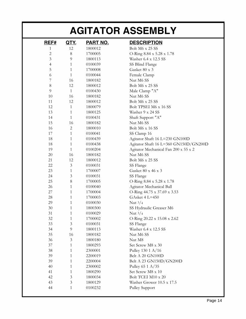
AGITATOR ASSEMBLYREF# QTY. PART NO. DESCRIPTION
1 12 1800012 Bolt M6 x 25 SS2 8 1700005 O-Ring 8.84 x 5.28 x 1.783 9 1800113 Washer 6.4 x 12.5 SS4 1 0100039 SS Blind Flange5 1 1700008 Gasket 80 x 36 1 0100044 Female Clamp7 16 1800182 Nut M6 SS8 12 1800012 Bolt M6 x 25 SS9 1 0100430 Male Clamp "A"10 16 1800182 Nut M6 SS11 12 1800012 Bolt M6 x 25 SS12 1 1800079 Bolt TPSEI M6 x 16 SS13 1 1800125 Washer 9 x 24 SS14 1 0100431 Shaft Support "A"15 16 1800182 Nut M6 SS16 2 1800010 Bolt M6 x 16 SS17 1 0100041 SS Clamp 1618 1 0100439 Agitator Shaft 16 L=230 GN100D18 1 0100438 Agitator Shaft 16 L=360 GN150D/GN200D19 1 0100204 Agitator Mechanical Fan 200 x 55 x 220 16 1800182 Nut M6 SS21 12 1800012 Bolt M6 x 25 SS22 3 0100031 SS Flange23 1 1700007 Gasket 80 x 46 x 324 3 0100031 SS Flange25 8 1700005 O-Ring 8.84 x 5.28 x 1.7826 1 0100040 Agitator Mechanical Ball27 1 1700004 O-Ring 44.75 x 37.69 x 3.5328 1 1700003 GAsket 4 L=45029 1 0100030 Nut 3/430 1 1800300 SS Hydraulic Greaser M631 1 0100029 Nut 3/432 1 1700002 O-Ring 20.22 x 15.08 x 2.6233 3 0100031 SS Flange34 9 1800113 Washer 6.4 x 12.5 SS35 16 1800182 Nut M6 SS36 3 1800180 Nut M837 1 1800293 Set Screw M8 x 3038 1 2300001 Pulley 130 1 A/1639 1 2200019 Belt A 20 GN100D39 1 2200004 Belt A 23 GN150D/GN200D40 1 2300002 Pulley 65 1 A/3541 1 1800290 Set Screw M8 x 1042 3 1800034 Bolt TCEI M10 x 2043 3 1800129 Washer Grower 10.5 x 17.544 1 0100232 Pulley Support

Page 15
SPRAYER BOOM

Page 16
SPRAYER BOOMREF# QTY. PART NO. DESCRIPTION
1 4 0100097 Blind Plug 1/22 4 1700021 Gasket 193 2 2000011 SS Tube 20/5004 2 1600024 Complete Hose 10 x 19 L=6205 4 1300003 Self Lock Nut Connector 10 x 196 4 1700010 Gasket7 2 0100111 Support G28B8 2 1800186 Self Lock Nut M109 2 1800041 Bolt M10 x 4510 2 2000018 SS Tube 20/500 G14B10 2 2000002 SS Tube 20/500 G20B10 2 2000011 SS Tube 20/500 G28B11 12 0100098 Plate12 6 1800059 Bolt M8 x 2513 6 1800180 Nut M814 2 1800200 Nut M1615 1 0100102 Inferior Support G14B & G20B16 8 0100107 Plate17 4 0100108 Clamp18 8 1800130 Washer 1019 8 1800036 Bolt M10 x 2520 1 2000012 SS Tube 20/500 G14B & G20B20 1 2000003 SS Tube 20/500 G28B21 2 0100118 Support G14B21 2 0100104 Support G20B21 2 0100110 Support G28B22 2 0100105 Pin23 4 0100106 Washer 20 x 5524 4 1800165 Washer 2025 2 2500002 Spring26 2 1800212 Nut M20 x 1.527 2 1800195 Nut M1428 1 0100103 Superior Support G14B & G20B29 18-34 1800002 Bolt M5 x 1630 9-17 0800004 Nozzle Buckle31 9-17 1700020 O-Ring 1032 9-17 0800062 Nozzle Body33 9-17 1400036 Anti-Drip34 9-17 1400037 Filter35 9-17 0800076 Complete Nozzle Assembly36 9-17 1700022 Gasket 1037 1 1300022 Nipple MF 1/2 - 3/838 9-17 0800071 Ring Nut39 9-17 0800072 80 Boom Nozzle (Brass)40 6 1800179 Nut M6
Continued.....

SPRAYER BOOM
Page 17
REF# QTY. PART NO. DESCRIPTION
41 2 0100112 Support42 6 1800014 Bolt M6 x 2043 18-34 400100 Bolt & Nut44 9-17 400020.030 O-Ring D.6 x 2.545 9-17 402225.010 Nozzle Body46 9-17 00226010 Diaphragm, Anti-Drip47 9-17 400020.020 Nozzle Clamp48 9-17 00226011 Anti-Drip Assembly49 9-17 00226002 Nut 3/4" GAS50 9-17 02311000 Filter51 9-17 02309010 Gasket52 9-17 30-04F80RE Jet 80O (Red)
52A 9-17 30-03F220UB Jet 110O (Blue)53 9-17 402900 Cap, Quick Coupling54 9-17 402225 Complete Nozzle Assembly (96)
NOZZLE SPACING
Page 18
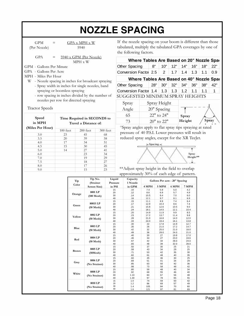
If the nozzle spacing on your boom is different than thosetabulated, multiply the tabulated GPA coverages by one ofthe following factors.
Other Spacing 8" 10" 12" 14" 16" 18" 22"Conversion Factor 2.5 2 1.7 1.4 1.3 1.1 0.9
Where Tables Are Based on 20" Nozzle Spac
Other Spacing 28" 30" 32" 34" 36" 38" 42"Conversion Factor 1.4 1.3 1.3 1.2 1.1 1.1 1
Where Tables Are Based on 40" Nozzle Spac
SUGGESTED MINIMUM SPRAY HEIGHTSSpray Height20" Spacing
65 22" to 24"73 20" to 22"
SprayAngle
OSpray angles apply to flat spray tips spraying at ratedpressure of 40 P.S.I. Lower pressures will result inreduced spray angles, except for the XR TeeJet.
**Adjust spray height in the field to overlap approximately 30% of each edge of pattern.
100 feet 200 feet 300 feet3.0 23 45 683.5 20 39 584.0 17 34 514.5 15 30 455.0 14 27 416.0 23 347.0 19 297.5 18 278.0 17 269.0 15 23
Speedin MPH
(Miles Per Hour)
Time Required in SECONDS toTravel a Distance of:
GPM = GPA x MPH x W(Per Nozzle) 5940
GPA = 5940 x GPM (Per Nozzle)MPH x W
GPM - Gallons Per MinuteGPA - Gallons Per AcreMPH - Miles Per Hour
W - Nozzle spacing in inches for broadcast spraying- Spray width in inches for single nozzles, band
spraying or boomless spraying- row spacing in inches divided by the number of
nozzles per row for directed spraying
Tractor Speeds
4 MPH 5 MPH 6 MPH 7 MPH
Orange8001 LP
(100 Mesh)
15203040
.10
.12
.14
.16
7.48.6
10.512.1
5.96.98.49.7
5.05.77.08.1
4.24.96.06.9
Green80015 LP
(50 Mesh)
15203040
.15
.17
.21
.24
11.112.915.818.1
8.910.312.614.5
7.48.6
10.512.1
6.47.49.0
10.4
Yellow8002 LP
(50 Mesh)
15203040
.20
.23
.28
.33
14.917.221.024.0
11.913.716.819.4
9.911.414.016.1
8.59.8
12.013.8
Blue8003 LP
(50 Mesh)
15203040
.30
.35
.42
.49
22263236
17.821.025.029.0
14.917.221.024.0
12.714.718.021.0
Red8004 LP
(50 Mesh)
15203040
.40
.46
.57
.65
30344248
27273439
19.823.028.032.0
17.019.624.028.0
Brown8005 LP
(50Mesh)
15203040
.50
.58
.71
.82
37435361
30344248
25293540
21253035
Grey8006 LP
(No Strainer)
15203040
.60
.69
.85
.98
45516373
36415058
30344248
25293642
White8008 LP
(No Strainer)
15203040
.80
.921.101.30
59698497
48556778
40465665
34404855
8010 LP(No Strainer)
15203040
1.01.21.41.6
7486
105121
59698497
50577081
42496069
Gallons Per acre - 20" SpacingTipColor
Tip No.(Strainer
Screen Size)
LiquidPressurein PSI
Capacity1 Nozzlein GPM

TOMMY GUN (GHT)
Page 19

TOMMY GUN (GHT)
Page 20
REF# QTY. PART NO. DESCRIPTION
1 1 0800080 Nozzle 1.51 1 0800081 Nozzle 1.81 1 0800082 Nozzle 2.01 1 0800083 Nozzle 2.81 1 0800084 Nozzle 3.01 1 0800085 Nozzle 3.52 1 0800086 Jet Support3 1 0800087 Gasket4 1 0800088 Body5 2 0800089 Gasket6 1 0800090 Bushing7 1 0800091 Washer8 1 0800092 Bolt9 1 0800093 Bolt10 1 0800094 Nut11 1 0800095 Plug12 1 0800096 Gasket13 1 0800097 Spring14 1 0800098 Nut15 1 0800099 Washer16 1 0800100 Washer17 1 0800101 Pin18 1 0800102 Nut19 1 0800103 Spring20 1 0800104 Plug21 1 0800105 Gasket22 1 0800106 Handle23 1 0800107 Shaft24 1 0800108 Gasket25 1 0800109 Handle26 1 0800110 Lever27 1 0800111 Plug28 1 0800112 Fork29 2 0800113 Bolt30 1 0800114 Gasket31 1 GHT Complete Handgun
RUN OF FLUIDS
Page 21
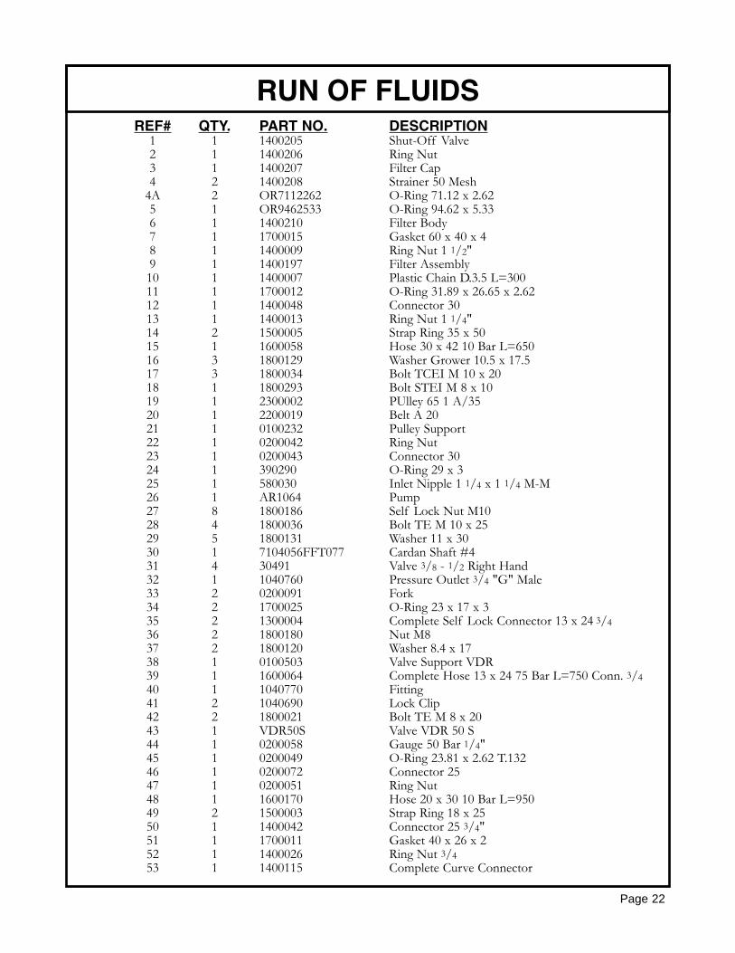
RUN OF FLUIDS
Page 22
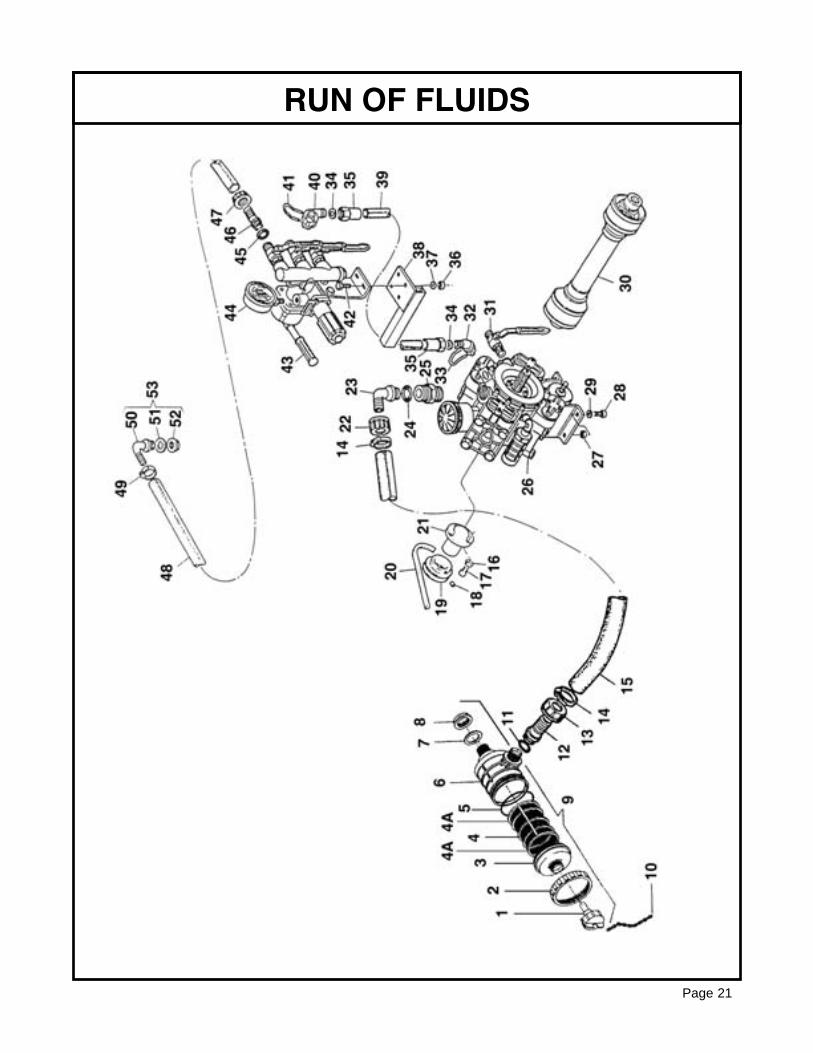
REF# QTY. PART NO. DESCRIPTION1 1 1400205 Shut-Off Valve2 1 1400206 Ring Nut3 1 1400207 Filter Cap4 2 1400208 Strainer 50 Mesh
4A 2 OR7112262 O-Ring 71.12 x 2.625 1 OR9462533 O-Ring 94.62 x 5.336 1 1400210 Filter Body7 1 1700015 Gasket 60 x 40 x 48 1 1400009 Ring Nut 1 1/2"9 1 1400197 Filter Assembly10 1 1400007 Plastic Chain D.3.5 L=30011 1 1700012 O-Ring 31.89 x 26.65 x 2.6212 1 1400048 Connector 3013 1 1400013 Ring Nut 1 1/4"14 2 1500005 Strap Ring 35 x 5015 1 1600058 Hose 30 x 42 10 Bar L=65016 3 1800129 Washer Grower 10.5 x 17.517 3 1800034 Bolt TCEI M 10 x 20 18 1 1800293 Bolt STEI M 8 x 10¹⁹ 1 2300002 PUlley 65 1 A/3520 1 2200019 Belt A 2021 1 0100232 Pulley Support22 1 0200042 Ring Nut23 1 0200043 Connector 3024 1 390290 O-Ring 29 x 325 1 580030 Inlet Nipple 1 1/4 x 1 1/4 M-M26 1 AR1064 Pump27 8 1800186 Self Lock Nut M1028 4 1800036 Bolt TE M 10 x 2529 5 1800131 Washer 11 x 3030 1 7104056FFT077 Cardan Shaft #431 4 30491 Valve 3/8 - 1/2 Right Hand32 1 1040760 Pressure Outlet 3/4 "G" Male33 2 0200091 Fork34 2 1700025 O-Ring 23 x 17 x 335 2 1300004 Complete Self Lock Connector 13 x 24 3/436 2 1800180 Nut M837 2 1800120 Washer 8.4 x 1738 1 0100503 Valve Support VDR39 1 1600064 Complete Hose 13 x 24 75 Bar L=750 Conn. 3/440 1 1040770 Fitting41 2 1040690 Lock Clip42 2 1800021 Bolt TE M 8 x 2043 1 VDR50S Valve VDR 50 S44 1 0200058 Gauge 50 Bar 1/4" 45 1 0200049 O-Ring 23.81 x 2.62 T.13246 1 0200072 Connector 2547 1 0200051 Ring Nut48 1 1600170 Hose 20 x 30 10 Bar L=95049 2 1500003 Strap Ring 18 x 2550 1 1400042 Connector 25 3/4"51 1 1700011 Gasket 40 x 26 x 252 1 1400026 Ring Nut 3/453 1 1400115 Complete Curve Connector

AR1064 PUMP ASSEMBLY
Page 23
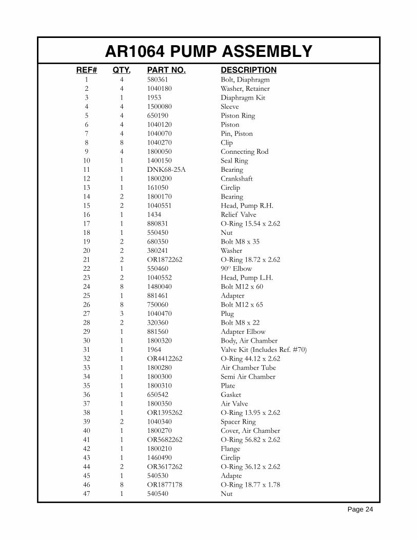
Page 24
AR1064 PUMP ASSEMBLYREF# QTY. PART NO. DESCRIPTION
1 4 580361 Bolt, Diaphragm2 4 1040180 Washer, Retainer3 1 1953 Diaphragm Kit4 4 1500080 Sleeve5 4 650190 Piston Ring6 4 1040120 Piston7 4 1040070 Pin, Piston8 8 1040270 Clip9 4 1800050 Connecting Rod10 1 1400150 Seal Ring11 1 DNK68-25A Bearing12 1 1800200 Crankshaft13 1 161050 Circlip14 2 1800170 Bearing15 2 1040551 Head, Pump R.H.16 1 1434 Relief Valve17 1 880831 O-Ring 15.54 x 2.6218 1 550450 Nut19 2 680350 Bolt M8 x 3520 2 380241 Washer21 2 OR1872262 O-Ring 18.72 x 2.6222 1 550460 90O Elbow23 2 1040552 Head, Pump L.H.24 8 1480040 Bolt M12 x 6025 1 881461 Adapter26 8 750060 Bolt M12 x 6527 3 1040470 Plug28 2 320360 Bolt M8 x 2229 1 881560 Adapter Elbow30 1 1800320 Body, Air Chamber31 1 1964 Valve Kit (Includes Ref. #70)32 1 OR4412262 O-Ring 44.12 x 2.6233 1 1800280 Air Chamber Tube34 1 1800300 Semi Air Chamber35 1 1800310 Plate36 1 650542 Gasket37 1 1800350 Air Valve38 1 OR1395262 O-Ring 13.95 x 2.6239 2 1040340 Spacer Ring40 1 1800270 Cover, Air Chamber41 1 OR5682262 O-Ring 56.82 x 2.6242 1 1800210 Flange43 1 1460490 Circlip44 2 OR3617262 O-Ring 36.12 x 2.6245 1 540530 Adapte46 8 OR1877178 O-Ring 18.77 x 1.7847 1 540540 Nut
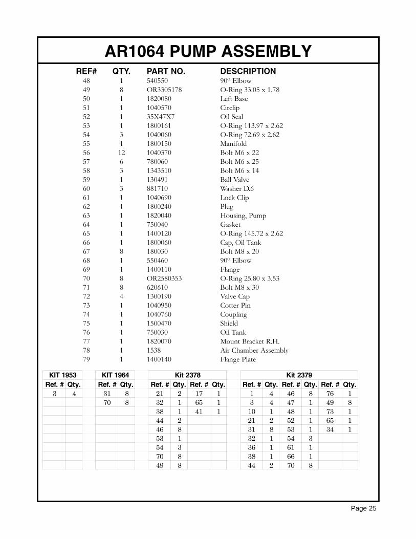
Page 25
AR1064 PUMP ASSEMBLYREF# QTY. PART NO. DESCRIPTION
48 1 540550 90O Elbow49 8 OR3305178 O-Ring 33.05 x 1.7850 1 1820080 Left Base51 1 1040570 Circlip52 1 35X47X7 Oil Seal53 1 1800161 O-Ring 113.97 x 2.6254 3 1040060 O-Ring 72.69 x 2.6255 1 1800150 Manifold56 12 1040370 Bolt M6 x 2257 6 780060 Bolt M6 x 2558 3 1343510 Bolt M6 x 1459 1 130491 Ball Valve60 3 881710 Washer D.661 1 1040690 Lock Clip62 1 1800240 Plug63 1 1820040 Housing, Pump64 1 750040 Gasket65 1 1400120 O-Ring 145.72 x 2.6266 1 1800060 Cap, Oil Tank67 8 180030 Bolt M8 x 2068 1 550460 90O Elbow69 1 1400110 Flange70 8 OR2580353 O-Ring 25.80 x 3.5371 8 620610 Bolt M8 x 3072 4 1300190 Valve Cap73 1 1040950 Cotter Pin74 1 1040760 Coupling75 1 1500470 Shield76 1 750030 Oil Tank77 1 1820070 Mount Bracket R.H.78 1 1538 Air Chamber Assembly79 1 1400140 Flange Plate
Ref. # Qty. Ref. # Qty. Ref. # Qty. Ref. # Qty. Ref. # Qty. Ref. # Qty. Ref. # Qty.3 4 31 8 21 2 17 1 1 4 46 8 76 1
70 8 32 1 65 1 3 4 47 1 49 838 1 41 1 10 1 48 1 73 144 2 21 2 52 1 65 146 8 31 8 53 1 34 153 1 32 1 54 354 3 36 1 61 170 8 38 1 66 149 8 44 2 70 8
KIT 1953 KIT 1964 Kit 2378 Kit 2379

Page 26
VDR50S VALVE ASSEMBLY
REF# QTY. PART NO. DESCRIPTION
1 1 550370 Input Hose Tail2 1 550242 Fly Nut Input Outlet3 2 550350 O-Ring 132 23.81 x 2.624 1 1040780 Threaded Nipple5 1 550040 O-Ring 3106 26.65 x 2.626 1 1040670 Piston8 1 1040660 Valve Seat9 5 30490 Control Valve
10 2 1040690 Nipple11 1 550545 Pressure Gauge12 1 1040680 Body13 8 390180 O-Ring 3075 18.72 x 2.6214 3 30171 Plug15 1 1040820 Elastic Pin16 4 180030 Pulley 8M x 2017 1 1040720 Control Body18 1 1040730 Handle19 1 1080200 O-Ring 5.6 x 2.2

Page 27
VDR50S VALVE ASSEMBLYREF# QTY. PART NO. DESCRIPTION
20 1 1040700 Control Body Shaft21 1 850680 Spring22 1 850660 Outlet Valve 13/16"23 2 850650 Outlet Seat24 2 740290 O-Ring 2056 14 x 1.7825 1 1040710 O-Ring26 1 104060 Main Body27 1 680560 Screw 6M x 1528 1 1040650 Spring29 1 1040640 Valve30 1 1040630 Diaphragm31 1 880830 O-Ring 3062 15.54 x 2.6232 1 1040620 Piston33 1 850440 Spring Seat34 1 1040830 Spring35 1 394770 Spring Body36 1 1040610 Valve Body37 4 550331 Lock Washer38 4 1040370 Allen Bolt39 1 394790 Valve Handle40 1 480550 Circlip45 1 1040810 Hose Fitting46 1 1040790 Nut47 1 1040800 Sleeve48 1 1040770 Fitting49 1 550210 Input Tube50 2 390270 Nut 8M H 6.551 2 180370 Pulley 8M x 2552 1 850690 Bracket53 1 770130 O-Ring 20.35 x 1.7854 1 1150650 Bolt M3 x 6055 2 960160 O-Ring 17.86 x 2.62
Part Number Qty. Part Number Qty. Part Number Qty.390180 4 1040640 1 390180 41080200 1 1040630 1 1080200 1740290 2 850660 1 740290 2550350 2 850680 1 550350 2550040 1 850650 2 550040 1880830 1 394790 1 880830 11040710 1 1040650 1 1040710 1960160 2 1040690 2 770130 1770130 1 1040820 1
KIT 1955 (O-Ring) " " KIT 1956 (Internal Parts) " "REPAIR KIT FOR VDR50 CONTROL VALVE

Page 28
DRIVELINE ASSEMBLY 7104056FFT077
REF # QTY. PART NO. DESCRIPTION
1 2 572040351 RS Yoke 1 3/8 6 Spline2 2 41204 #4 Cross Kit3 1 204046851 Outer Tube Yoke4 1 341038000 Roll Pin O.T.5 1 225120860 Outer Drive Tube 860 mm6 1 225100860 Inner Drive Tube 860 mm7 1 204046852 Inner Tube Yoke8 1 341048000 Roll Pin I.T.9 2 240002451 RS Collar Kit
10 1 255040005 Shield Bearing Outer11 1 255040006 Shield Bearing Inner12 2 252000001 Safety Chain13 1 5F04086F6 Complete Shield w/Bearings

Page 29
GEARMORE, INC., warrants each new Gearmore product to be free from defects in materi-al and workmanship for a period of twelve (12) months from date of purchase to the originalpurchaser. This warranty shall not apply to implements or parts that have been subject tomisuse, negligence, accident, or that have been altered in any way.
Our obligation shall be limited to repairing or replacement of any part, provided that suchpart is returned within thirty (30) days from date of failure to Gearmore through the dealerfrom whom the purchase was made, transportation charges prepaid.
This warranty shall not be interpreted to render us liable for injury or damages of any kind ornature, direct, consequential or contingent, to person or property. This warranty does notextend to loss of crops, loss because of delay in harvesting or any other expenses, for anyother reasons.
Gearmore in no way warranties engines, tires, or other trade accessories, since these itemsare warranted separately by these respective manufacturers.
Gearmore reserves the right to make improvements in design or changes in specification atany time, without incurring any obligations to owners or units previously sold.
GEARMORE, INC.13477 Benson Ave.
Chino, CA 91710Always refer to and heed machine operating warning decals on machine.
LIMITED WARRANTY
The serial number of this product is stored in our computer database, thussubmitting a warranty registration card is not required.