3-phase power and network equations
TRANSCRIPT

Spyros Chatzivasileiadis
31730: Electric Power Engineering, fundamentals
3-phase power and Network Equations
12 September 2017
If not otherwise indicated, all figures are taken from the course textbook: J. D. Glover, T. J. Overbye, M. S. Sarma, Power System Analysis and Design, Sixth Edition - SI, Cengage Learning, 2016

DTU Electrical Engineering, Technical University of Denmark
Reviewing previous lecture
• For 5 minutes discuss with the person sitting next to you about:
– Three main points we discussed in the last lecture
– One topic or concept that is not so clear and you would like to hear again about it
2 Spyros Chatzivasileiadis

DTU Electrical Engineering, Technical University of Denmark
The goals for today• Line-to-neutral and line-to-line voltage
• Δ-loads and Y-loads
• Single-line diagram
• Power in three-phase balanced systems
• Network equations
• Bus Admittance Matrix
3 Spyros Chatzivasileiadis

DTU Electrical Engineering, Technical University of Denmark
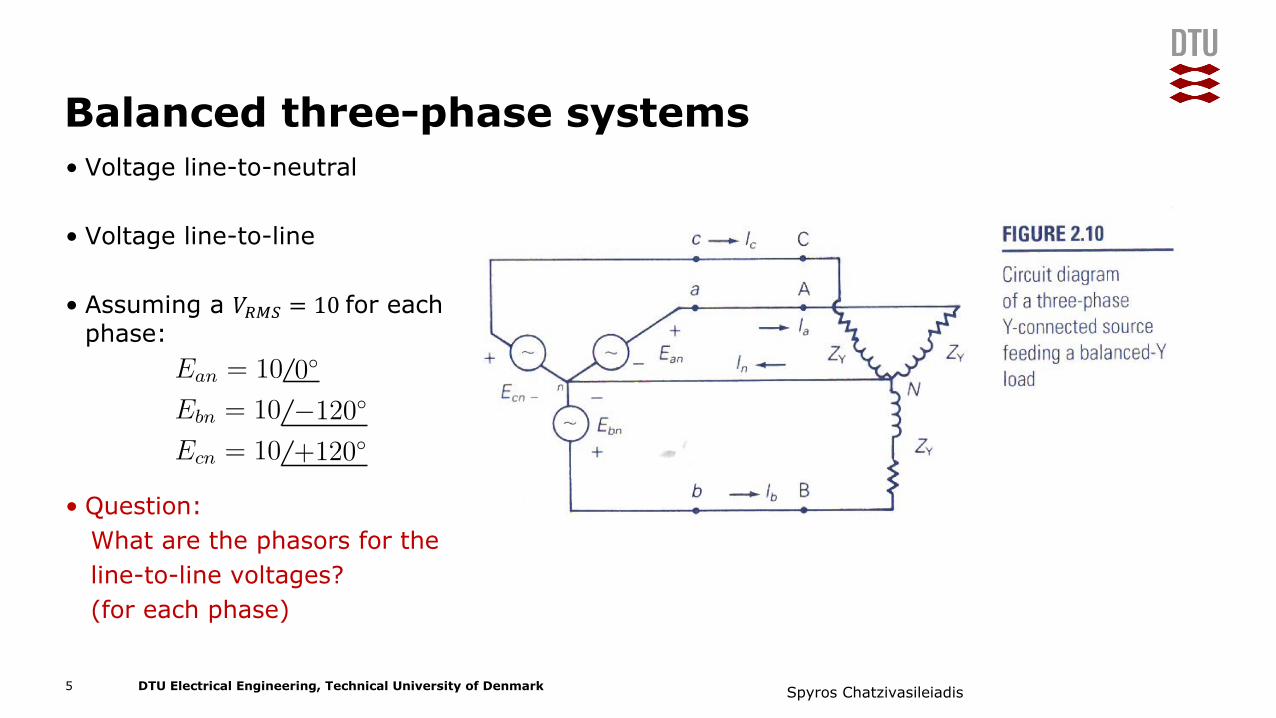
Balanced three-phase systems
• Voltage line-to-neutral
• Voltage line-to-line
• Question:What are the phasors for the line to neutral voltages?(for each phase)
4 Spyros Chatzivasileiadis
DTU Electrical Engineering, Technical University of Denmark
Balanced three-phase systems• Voltage line-to-neutral
• Voltage line-to-line
• Assuming a 𝑉"#$ = 10for each phase:
• Question:What are the phasors for the line-to-line voltages?(for each phase)
S = V · I∗
ZY =Z∆
3
p3φ(t) = P3φ = 3VLNIL cos(δ − β)
Ean = 10 0◦
Ebn = 10 −120◦
Ecn = 10 +120◦
7 DTU Electrical Engineering 31730: Electric Power Engineering, Fundamentals Sep 8, 2017
5 Spyros Chatzivasileiadis
DTU Electrical Engineering, Technical University of Denmark
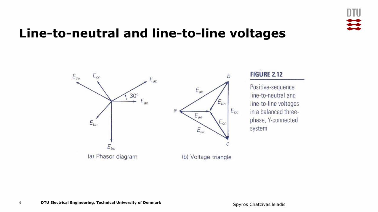
Line-to-neutral and line-to-line voltages
6 Spyros Chatzivasileiadis

DTU Electrical Engineering, Technical University of Denmark
Delta-Wye Loads and transformation
S = V · I∗
ZY =Z∆
3
p3φ(t) = pa(t) + pb(t) + pc(t) =
3VLNIL cos(δ − β) + VLNIL[cos(2ωt+ δ + β)
cos(2ωt+ δ + β − 240◦)+ cos(2ωt+ δ + β + 240◦)]
7 DTU Electrical Engineering 31730: Electric Power Engineering, Fundamentals Sep 8, 2017
7 Spyros Chatzivasileiadis
• Delta vs Wye
• Delta-Volt. = 3� × Wye-Volt.
• Delta-Curr. = 3� ×Wye-Curr.
If I want to transform:
• Ι- = 3� ./0/= 3� 1� .2
0/⇒45
65= 3 42
6/

DTU Electrical Engineering, Technical University of Denmark
Interesting fact: (outside the scope of this course)
Delta-Wye switch for induction motor start
Spyros Chatzivasileiadis8
• Many induction motors use a delta-wye switch when they start• wye-start-delta-run• Reason:
• Induction motors have usually very high currents during the first seconds they start (up to 6x the nominal current)
• Apply line-neutral voltage instead of line-line à lower voltage• In this case, impedance values in the wye-formation are the same as in
the delta-formation (it is just a different connection)• è Reduces the inrush current, i.e. less current when the motor starts!
Video: https://www.youtube.com/watch?v=km8MSWm39Z0

DTU Electrical Engineering, Technical University of Denmark
Three-phase to single line diagram
9 Spyros Chatzivasileiadis

DTU Electrical Engineering, Technical University of Denmark
Three-phase to single line diagram• Three main points:
1. Voltages must be RMS values
2. Transform line-to-line voltages to line-to-neutral
3. Transform all Δ-loads to Y-loads
10 Spyros Chatzivasileiadis

DTU Electrical Engineering, Technical University of Denmark
Power balanced in three-phase systems
• The three-phase instantaneous power remains constant!
• Relationship between line-to-line and line-to-neutral differs by √3
• Similar for Q
S = V · I∗
ZY =Z∆
3
p3φ(t) =pa(t) + pb(t) + pc(t) =
3VLNIL cos(δ − β) + VLNIL[cos(2ωt+ δ + β)+
cos(2ωt+ δ + β − 240◦)+
cos(2ωt+ δ + β + 240◦)]
p3φ(t) = P3φ = 3VLNIL cos(δ − β)
p3φ(t) = P3φ =√3VLLIL cos(δ − β)
7 DTU Electrical Engineering 31730: Electric Power Engineering, Fundamentals Sep 8, 2017
S = V · I∗
ZY =Z∆
3
p3φ(t) =pa(t) + pb(t) + pc(t) =
3VLNIL cos(δ − β) + VLNIL[cos(2ωt+ δ + β)+
cos(2ωt+ δ + β − 240◦)+
cos(2ωt+ δ + β + 240◦)]
p3φ(t) = P3φ = 3VLNIL cos(δ − β)
p3φ(t) = P3φ =√3VLLIL cos(δ − β)
7 DTU Electrical Engineering 31730: Electric Power Engineering, Fundamentals Sep 8, 2017
S = V · I∗
ZY =Z∆
3
p3φ(t) =pa(t) + pb(t) + pc(t) =
3VLNIL cos(δ − β) + VLNIL[cos(2ωt+ δ + β)+
cos(2ωt+ δ + β − 240◦)+
cos(2ωt+ δ + β + 240◦)]
p3φ(t) = P3φ = 3VLNIL cos(δ − β)
p3φ(t) = P3φ =√3VLLIL cos(δ − β)
7 DTU Electrical Engineering 31730: Electric Power Engineering, Fundamentals Sep 8, 2017
S = V · I∗
ZY =Z∆
3
p3φ(t) = P3φ = 3VLNIL cos(δ − β)
p3φ(t) = P3φ =√3VLLIL cos(δ − β)
p3φ(t) = Q3φ = 3VLNIL sin(δ − β)
7 DTU Electrical Engineering 31730: Electric Power Engineering, Fundamentals Sep 8, 2017
11 Spyros Chatzivasileiadis
DTU Electrical Engineering, Technical University of Denmark
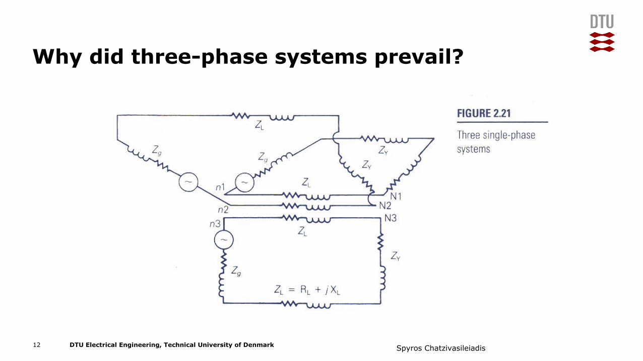
Why did three-phase systems prevail?
12 Spyros Chatzivasileiadis
DTU Electrical Engineering, Technical University of Denmark
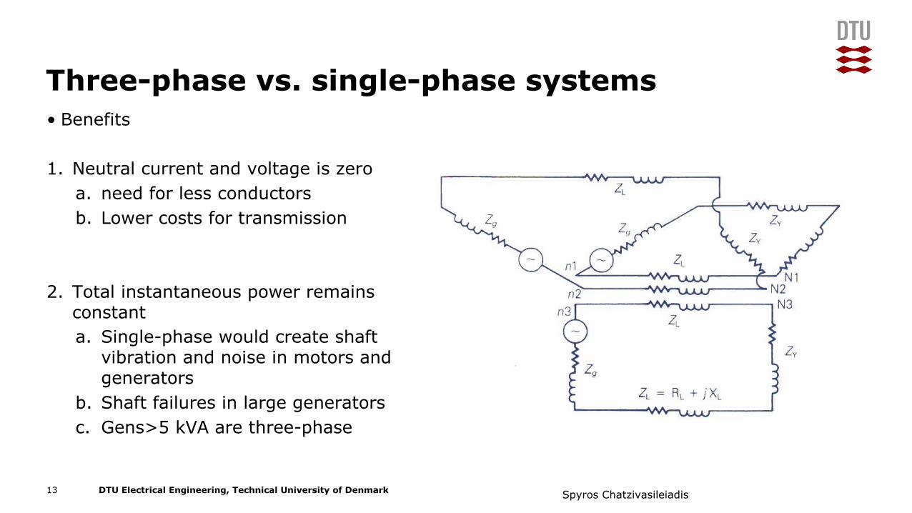
Three-phase vs. single-phase systems• Benefits
1. Neutral current and voltage is zeroa. need for less conductorsb. Lower costs for transmission
2. Total instantaneous power remains constanta. Single-phase would create shaft
vibration and noise in motors and generators
b. Shaft failures in large generators c. Gens>5 kVA are three-phase
13 Spyros Chatzivasileiadis

DTU Electrical Engineering, Technical University of Denmark
Network equations
How much is 𝐼:̅?
Assuming 𝑉<:, 𝑉<>, 𝑉<1 and 𝑦<:>, 𝑦<:1,𝑦<>1 known
Bus Reactance Matrix
V 1 V 2
V 3
I1 y12 I2
y13 y23
How much is P1?
1 DTU Electrical Engineering 31765: Optimization in modern power systems Sep 12, 2017
14 Spyros Chatzivasileiadis

DTU Electrical Engineering, Technical University of Denmark
Network equationsHow much is 𝐼:̅?
Assuming 𝑉<:, 𝑉<>, 𝑉<1 and 𝑦<:>, 𝑦<:1,𝑦<>1 known
Step 1:
How much is 𝐼:̅>?
I12 =V 1 − V 2
z12I12 = y12(V 1 − V 2)
I1 = I12 + I13
I1 = y12(V 1 − V 2) + y13(V 1 − V 3)
I1 = (y12 + y13)V 1 − y12V 2 − y13V 3
I1 =[y12 + y13 −y12 −y13
]⎡
⎣V 1
V 2
V 3
⎤
⎦
2 DTU Electrical Engineering 31765: Optimization in modern power systems Sep 12, 2017
Bus Reactance Matrix
V 1 V 2
V 3
I1 y12I12 I2
I13
y13 y23
How much is P1?
4 DTU Electrical Engineering 31765: Optimization in modern power systems Sep 12, 2017
15 Spyros Chatzivasileiadis

DTU Electrical Engineering, Technical University of Denmark
Network equationsHow much is 𝐼:̅?
Assuming 𝑉<:, 𝑉<>, 𝑉<1 and 𝑦<:>, 𝑦<:1,𝑦<>1 known
Step 1:
Step 2:
I12 =V 1 − V 2
z12I12 = y12(V 1 − V 2)
I1 = I12 + I13
I1 = y12(V 1 − V 2) + y13(V 1 − V 3)
I1 = (y12 + y13)V 1 − y12V 2 − y13V 3
I1 =[y12 + y13 −y12 −y13
]⎡
⎣V 1
V 2
V 3
⎤
⎦
2 DTU Electrical Engineering 31765: Optimization in modern power systems Sep 12, 2017
I12 =V 1 − V 2
z12I12 = y12(V 1 − V 2)
I1 = I12 + I13
I1 = y12(V 1 − V 2) + y13(V 1 − V 3)
I1 = (y12 + y13)V 1 − y12V 2 − y13V 3
I1 =[y12 + y13 −y12 −y13
]⎡
⎣V 1
V 2
V 3
⎤
⎦
2 DTU Electrical Engineering 31765: Optimization in modern power systems Sep 12, 2017
⟹I12 =
V 1 − V 2
z12I12 = y12(V 1 − V 2)
I1 = I12 + I13
I1 = y12(V 1 − V 2) + y13(V 1 − V 3)
I1 = (y12 + y13)V 1 − y12V 2 − y13V 3
I1 =[y12 + y13 −y12 −y13
]⎡
⎣V 1
V 2
V 3
⎤
⎦
2 DTU Electrical Engineering 31765: Optimization in modern power systems Sep 12, 2017
Bus Reactance Matrix
V 1 V 2
V 3
I1 y12I12 I2
I13
y13 y23
How much is P1?
4 DTU Electrical Engineering 31765: Optimization in modern power systems Sep 12, 2017
16 Spyros Chatzivasileiadis

DTU Electrical Engineering, Technical University of Denmark
I12 =V 1 − V 2
z12I12 = y12(V 1 − V 2)
I1 = I12 + I13
I1 = y12(V 1 − V 2) + y13(V 1 − V 3)
I1 = (y12 + y13)V 1 − y12V 2 − y13V 3
I1 =[y12 + y13 −y12 −y13
]⎡
⎣V 1
V 2
V 3
⎤
⎦
2 DTU Electrical Engineering 31765: Optimization in modern power systems Sep 12, 2017
Network equationsHow much is 𝐼:̅?Assuming 𝑉<:, 𝑉<>, 𝑉<1 and 𝑦<:>, 𝑦<:1,𝑦<>1 known
Step 1:
Step 2:
Step 3:
I12 =V 1 − V 2
z12I12 = y12(V 1 − V 2)
I1 = I12 + I13
I1 = y12(V 1 − V 2) + y13(V 1 − V 3)
I1 = (y12 + y13)V 1 − y12V 2 − y13V 3
I1 =[y12 + y13 −y12 −y13
]⎡
⎣V 1
V 2
V 3
⎤
⎦
2 DTU Electrical Engineering 31765: Optimization in modern power systems Sep 12, 2017
I12 =V 1 − V 2
z12I12 = y12(V 1 − V 2)
I1 = I12 + I13
I1 = y12(V 1 − V 2) + y13(V 1 − V 3)
I1 = (y12 + y13)V 1 − y12V 2 − y13V 3
I1 =[y12 + y13 −y12 −y13
]⎡
⎣V 1
V 2
V 3
⎤
⎦
2 DTU Electrical Engineering 31765: Optimization in modern power systems Sep 12, 2017
Bus Reactance Matrix
V 1 V 2
V 3
I1 y12I12 I2
I13
y13 y23
How much is P1?
4 DTU Electrical Engineering 31765: Optimization in modern power systems Sep 12, 2017
I12 =V 1 − V 2
z12I12 = y12(V 1 − V 2)
I1 = I12 + I13
I1 = y12(V 1 − V 2) + y13(V 1 − V 3) ⇒I1 = (y12 + y13)V 1 − y12V 2 − y13V 3
I1 =[y12 + y13 −y12 −y13
]⎡
⎣V 1
V 2
V 3
⎤
⎦
2 DTU Electrical Engineering 31765: Optimization in modern power systems Sep 12, 2017
I12 =V 1 − V 2
z12I12 = y12(V 1 − V 2)
I1 = I12 + I13
I1 = y12(V 1 − V 2) + y13(V 1 − V 3) ⇒I1 = (y12 + y13)V 1 − y12V 2 − y13V 3
I1 =[y12 + y13 −y12 −y13
]⎡
⎣V 1
V 2
V 3
⎤
⎦
2 DTU Electrical Engineering 31765: Optimization in modern power systems Sep 12, 2017
17 Spyros Chatzivasileiadis

DTU Electrical Engineering, Technical University of Denmark
Network equationsHow much is 𝐼:̅?Assuming 𝑉<:, 𝑉<>, 𝑉<1 and 𝑦<:>, 𝑦<:1,𝑦<>1 known
Step 1:
I12 =V 1 − V 2
z12I12 = y12(V 1 − V 2)
I1 = I12 + I13
I1 = y12(V 1 − V 2) + y13(V 1 − V 3)
I1 = (y12 + y13)V 1 − y12V 2 − y13V 3
I1 =[y12 + y13 −y12 −y13
]⎡
⎣V 1
V 2
V 3
⎤
⎦
2 DTU Electrical Engineering 31765: Optimization in modern power systems Sep 12, 2017
I12 =V 1 − V 2
z12I12 = y12(V 1 − V 2)
I1 = I12 + I13
I1 = y12(V 1 − V 2) + y13(V 1 − V 3)
I1 = (y12 + y13)V 1 − y12V 2 − y13V 3
I1 =[y12 + y13 −y12 −y13
]⎡
⎣V 1
V 2
V 3
⎤
⎦
2 DTU Electrical Engineering 31765: Optimization in modern power systems Sep 12, 2017
I12 =V 1 − V 2
z12I12 = y12(V 1 − V 2)
I1 = I12 + I13
I1 = y12(V 1 − V 2) + y13(V 1 − V 3)
I1 = (y12 + y13)V 1 − y12V 2 − y13V 3
I1 =[y12 + y13 −y12 −y13
]⎡
⎣V 1
V 2
V 3
⎤
⎦
2 DTU Electrical Engineering 31765: Optimization in modern power systems Sep 12, 2017
Bus Reactance Matrix
V 1 V 2
V 3
I1 y12I12 I2
I13
y13 y23
How much is P1?
4 DTU Electrical Engineering 31765: Optimization in modern power systems Sep 12, 2017
I12 =V 1 − V 2
z12I12 = y12(V 1 − V 2)
I1 = I12 + I13
I1 = y12(V 1 − V 2) + y13(V 1 − V 3) ⇒I1 = (y12 + y13)V 1 − y12V 2 − y13V 3
I1 =[y12 + y13 −y12 −y13
]⎡
⎣V 1
V 2
V 3
⎤
⎦
2 DTU Electrical Engineering 31765: Optimization in modern power systems Sep 12, 2017
I12 =V 1 − V 2
z12I12 = y12(V 1 − V 2)
I1 = I12 + I13
I1 = y12(V 1 − V 2) + y13(V 1 − V 3) ⇒I1 = (y12 + y13)V 1 − y12V 2 − y13V 3
I1 =[y12 + y13 −y12 −y13
]⎡
⎣V 1
V 2
V 3
⎤
⎦
2 DTU Electrical Engineering 31765: Optimization in modern power systems Sep 12, 2017
I12 =V 1 − V 2
z12I12 = y12(V 1 − V 2)
I1 = I12 + I13
I1 = y12(V 1 − V 2) + y13(V 1 − V 3) ⇒I1 = (y12 + y13)V 1 − y12V 2 − y13V 3
I1 =[y12 + y13 −y12 −y13
]⎡
⎣V 1
V 2
V 3
⎤
⎦
2 DTU Electrical Engineering 31765: Optimization in modern power systems Sep 12, 201718 Spyros Chatzivasileiadis

DTU Electrical Engineering, Technical University of Denmark
Network equationsHow much is 𝐼:̅?Assuming 𝑉<:, 𝑉<>, 𝑉<1 and 𝑦<:>, 𝑦<:1,𝑦<>1 known
Bus Reactance Matrix
V 1 V 2
V 3
I1 y12I12 I2
I13
y13 y23
How much is P1?
4 DTU Electrical Engineering 31765: Optimization in modern power systems Sep 12, 2017
I12 =V 1 − V 2
z12I12 = y12(V 1 − V 2)
I1 = I12 + I13
I1 = y12(V 1 − V 2) + y13(V 1 − V 3) ⇒I1 = (y12 + y13)V 1 − y12V 2 − y13V 3
I1 =[y12 + y13 −y12 −y13
]⎡
⎣V 1
V 2
V 3
⎤
⎦
2 DTU Electrical Engineering 31765: Optimization in modern power systems Sep 12, 2017
⎡
⎣I1I2I3
⎤
⎦ =
⎡
⎣y12 + y13 −y12 −y13−y12 y12 + y23 −y23−y13 −y12 y13 + y23
⎤
⎦
⎡
⎣V 1
V 2
V 3
⎤
⎦
I = YV
3 DTU Electrical Engineering 31765: Optimization in modern power systems Sep 12, 2017
19 Spyros Chatzivasileiadis
⎡
⎣I1I2I3
⎤
⎦ =
⎡
⎣y12 + y13 −y12 −y13−y12 y12 + y23 −y23−y13 −y23 y13 + y23
⎤
⎦
⎡
⎣V 1
V 2
V 3
⎤
⎦
I = YV
3 DTU Electrical Engineering 31765: Optimization in modern power systems Sep 12, 2017
DTU Electrical Engineering, Technical University of Denmark
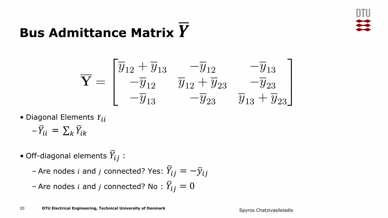
Bus Admittance Matrix 𝒀B
• Diagonal Elements 𝑌<DD–𝑌<DD = ∑ 𝑌<DG�
G
• Off-diagonal elements 𝑌<DH:– Are nodes 𝑖 and 𝑗 connected? Yes: 𝑌<DH = −𝑦<DH– Are nodes 𝑖 and 𝑗 connected? No : 𝑌<DH = 0
20 Spyros Chatzivasileiadis
Y =
⎡
⎣y12 + y13 −y12 −y13−y12 y12 + y23 −y23−y13 −y23 y13 + y23
⎤
⎦
4 DTU Electrical Engineering 31765: Optimization in modern power systems Sep 12, 2017